Version 4.0 LineDesign Engineering 11/1/04
|
|
|
- Wesley Tyler
- 5 years ago
- Views:
Transcription
1 Ple Lading Prgram (Transverse, Vertical, Guying & Buckling) User's Guide Versin 4.0 LineDesign Engineering 11/1/04
2 Cntents Intrductin 3 Descriptin f Tabs 4-7 Ple Data 7 Wire Data 8-9 Inputs, Drives & Flders Input Data Cell Reference List Outputs & Saving Files Items Mdeled, Assumptins & Unknwns Frequently Asked Questins (FAQ's) Macr Descriptins Wire Data Table 24 Equipment Data Table 25 Grades & Lading Districts 26 References 27 License Agreement 27 Cntact Infrmatin 27 Examples
3 Intrductin Purpse The main purpse f the Ple Lading prgram is t cmpare the rated grund-line strength f a ple t the applied lads acting n the ple. The strength f the ple and the applied lads are adjusted by using the apprpriate verlad factrs and strength factrs, as specified in the Natinal Electrical Safety Cde (NESC) r ther specialized requirements such as GO95, etc. The prgram will shw if the ple is capable f supprting the applied lads by calculating the mments (ft-lb's), percent lading, and stress values (psi). If the ple is nt capable f supprting the applied lads, then alternate designs must be mdeled, such as increasing the class f the ple, shrtening span lengths, reducing cnductr tensins, lwering attachment heights, reducing the diameter f the cables, reducing unguyed angles, guying the ple, etc. These alternate designs can be mdeled within the prgram, until an acceptable result is btained. Transverse Lading The limiting cnditin n mst distributin and transmissin wd ples is the transverse lading. Transverse lading means wind blwing at a 90 degree angle t a ple line, prducing a mment at the grund-line f the ple. The transverse lad calculatin cnsists f wind blwing n cnductrs & cables (with and withut ice cvering), wind blwing n the ple itself, and wind blwing n ther attached equipment. Als included in the calculatin are ther ladings due t line angles, tensin taps, and slack spans, cantilever (r eccentric) lading f imbalanced cnductrs and equipment. This is the mment calculatin that is made n the "calculatin" tab f the prgram. The results are als summarized n the "sum" tab f the prgram. Vertical Lading Vertical lading is rarely a limiting factr in ple lading, unless there is very heavy equipment attached t the ple, r the ple has dwnguys with very shrt guy leads (distance frm ple t anchr). The "sum" tab displays a ttal stress value which includes the transverse lading mments and als adds in any vertical lading n the ple. The vertical lading is usually a very small cmpnent in the verall stress n a ple. Ice and Wind Whether the cnductrs need t have a radial thickness f ice build-up assumed, befre the applicatin f wind, depends n the lading district requirements f yur part f the cuntry (see the NESC, GO95 r ther lading requirements). The wind speed required t be used in the calculatin als depends n yur lcatin. Jint Use The Ple Lading prgram is a very useful tl when dealing with jint-use ple cntacts, CATV/cmmunicatin cmpany make-ready wrk, adding additinal cnductrs, recnductring, r checking yur existing ple lading
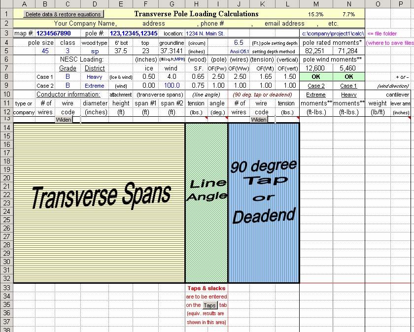
4 Descriptin f Tabs The prgram cnsists f the fllwing tabs (r sheets): Calculatin, picture, ther, guys, taps, sum, guying, headguy, buckle, stress, deflect, all pints, fixed pt. The tabs are selected at the bttm f the screen. Many users nly utilize and print ut the "calculatin" and/r the sum tab. The additinal tabs cver mre cmplex mdeling (taps), guying calculatins (guys, guying, headguy), mid-span clearance and ther infrmatin (ther), r cver special calculatins that were requested by users and are smetimes required (buckle, stress, deflect, all pints, fixed pt). Fllwing the calculatin and sum tabs, the ther mst frequently used tabs are the "taps", "guying", guys, and headguy tabs (if applicable). Each f these tabs and their use will be discussed belw. The inf at the tp f each tab (map, ple, lcatin, etc, is carried ver autmatically frm what is entered n the "calculatin" tab. Calculatin The "calculatin" tab f the prgram is where the majrity f the input data is entered fr cmmn cases. The ple infrmatin, calculatin lading criteria (NESC r GO95 grade f cnstructin, lading district, r ther ice and wind lading cnditins), and cnductr infrmatin are specified n this tab. The equivalent results frm the taps and guys tab are als displayed and used in the calculatins n this tab. The transverse and cantilever mments are calculated and displayed here. Picture The "picture" tab allws a digital picture t be inserted f the ple. This can be dne manually, r the use f the "Ctrl-J" macr can autmate the prcess (see details in the macr descriptin sectin). Other The "ther" tab is supplied fr thse wh wish t recrd mid-span clearance and temperature infrmatin fr the wires, cables r equipment. It can als be used t enter any ther infrmatin yu may want t recrd fr later reference
5 Guys This tab differs in functinality frm the "guying" and headguy tab. The guys tab allws the user t enter existing r prpsed guy infrmatin t mdel their effect n ple lading (transverse & vertical), and t see the guys ability t hld the transverse mments frm the ple, cnductrs, equipment, etc. The results f the frces due t these guy wires are transferred t ther tabs (calculatin, sum, and buckle). Status indicatrs displayed n the calculatin and sum tab will indicate whether the guys are strng enugh t hld the required lad. Please remember that the ple and guys cannt "share" lad, per the NESC. Either the ple r the guys must handle the entire lad in the particular directin they are resisting. When guys are used t meet strength requirements, they shall be cnsidered as taking the entire lad in the directin in which they act, the structure acting as a strut nly. See NESC Rule 261C2. The frces frm the "guys" tab are NOT included n the "guying" r headguy tab. In many cases, mst users will prbably use either the "guys" tab r use the "guying" r headguy tab, but nt bth methds. The guys tab was requested by users wh prefer t use this methd & t be cmparable t ther ple lading prgrams. The guy wire status indicatrs (n the calculatin and sum tabs) nly reflect guy infrmatin entered n the guys tab. A suggested methd fr using this tab is t mdel yur ple "as-is", then see if yu need additinal guying (i.e., if the ple is ver 100% laded). If s, yu can then use the "guying" tab (r headguy tab if applicable) t see what guying is required. Then enter the required guying n the "guys" tab, s the frces are reflected n the "calculatin", "sum", and "buckle" tabs. The default values used fr the guy tensins n the "guys" tab are the rated strengths f the guys. Yu may elect t type ver these values with the actual values required t hld yur lads, btained frm the "guying" tab. If yu are cncerned with buckling, then the use f this "guys" tab will be required, since the vertical dwnguy frces are carried ver t the "buckle" tab. The frces frm the "guying" tab hwever, are NOT carried ver t the "buckle" tab, and are NOT included in any f the ther calculatins, r ther tabs. S when yu are cncerned with buckling f guyed structures, yu will need t use the "guys" tab. Taps The "taps" tab allws the user t mdel taps, slacks, service drps, r cmplex mdeling nt available n the "calculatin" tab. This tab is useful when mdeling taps that are nt perpendicular t yur main line (perpendicular taps can either be mdeled n the calculatin tab, r n this tab). It is als used t mdel multiple taps at varius angles (which may als have varius cnductr sizes and/r tensins), r ther cmplex mdeling nt easily mdeled n the calculatin tab. The equivalent span lengths perpendicular t the wind directin and the equivalent tensins parallel t the wind directin are returned t the calculatin tab fr use in the transverse mments calculatins
6 Sum The "sum" tab summarizes the mments applied t the ple (as calculated n the "calculatin" tab), and als includes additinal stresses due t the vertical lading cmpnents acting n the ple. A breakdwn f the mments and stresses fr each lad categry is shwn n this tab. Guying The "guying" tab allws the calculatin f the required strength f dwnguys and anchrs, if the ple is nt capable f supprting the applied lads by itself (i.e., if the ple is ver 100% laded). In many cases, this "guying" tab will be the nly guying calculatins required (since in mst cases, buckling is nt a cncern). The Overlad Factrs (OF's) used in guying calculatins are based n the NESC r GO95 verlad factrs fr guying. The OF's used t calculate the ple lading may be different. Fr example, NESC table OF's will be used fr guying, even when "alternate" table OF's are used fr ple lading (n the "calculatin" and ther tabs relating t ple lading). The nly OF's fr guying specified by the NESC are the values in table The guying OF's are listed in a table n the "guying" tab, and are autmatically filled in based n the lading Grade & District selected n the "calculatin" tab. Als refer t the descriptin f the "guys" tab fr additinal infrmatin n guying. Headyguy The "headguy" tab allws the calculatin f the required strength f headguys r spanguys, if the ple is nt capable f supprting the applied lads by itself (i.e., if the ple is ver 100% laded). If the headguys r spanguys are attached t anther ple (such as a guy stub ple ), the required strength f the dwnguys and anchrs n that ple are als calculated n this tab. This tab uses the same calculatin methds as the guying tab. See the Overlad Factr cmments in the descriptin f the guying tab (abve). Als refer t the descriptin f the "guys" tab fr additinal infrmatin n guying. Buckle The "buckle" tab allws the user t check fr clumn buckling, using tw different buckling calculatin methds. Values calculated elsewhere within the prgram are used alng with a few additinal inputs selected n the "buckle" tab. These tw methds use different calculatins and are nt expected t prduce equivalent results. At the present time, the first f these buckling methds is the mst widely used methd
7 - 30 -
")
8 SAMPLE #1 Ple #25/764 3-Phase Line, with Unguyed Slack Span Tap (at 90 degree angle) 31
9 Transverse Ple Lading Calculatins 88.8% 103.6% map #: ple #: 25 lcatin: Sample #1 - methd 1 c:\cmpany\prject1\calc\ ple size class wd type 6' bt tp grundline (circum) 7.5 (Ft.) ple setting depth ple rated mments* 55 3 sp (inches) Ansi O5.1 setting depth methd 101,050 87,577 NESC Lading: (inches) (#/sq.ft,mph) (wd) (ple) (wires) (tensin) (vertical) ple wind mments** Grade District ice wind S.F. OF(Pw) OF(Ww) OF(Wt) OF(vert) 20,319 8,575 Case 1 B Heavy (Ice & wind) OK Guys Hld Case 2 B Extreme (wind) Case 2 Case 1 Cnductr infrmatin: attachment (transverse spans) (line angle) (90 deg. tap r deadend) Extreme Heavy type r # f wire diameter height span #1 span #2 tensin angle # f wire tensin mments** mments** cmpany wires cde (inches) (ft) (ft) (ft) (lbs.) (deg.) wires cde (lbs.) (ft-lbs.) (ft-lbs.) pwer / ,249 18,654 pwer / ,014 17,279 pwer / ,789 15,905 pwer 1 2/ / ,437 12,999 catv 1 d ,604 8,770 catv 1 d ,272 8,506 Taps & slacks are t be entered n the "Taps" tab (equiv. results are shwn in this area) Ttal cantilever (eccentric) lading frm imbalanced cnductrs => Equipment wind lading: Equip. cantilever lading: quantity equip. diameter height area munt. ht. shape factr weight lever arm angle (inches) (inches) (sq.ft.) (ft) 1.0=cyl, (lbs.) (inches) (deg.) 1.6=flat (wind directin = 90 deg.) 25 kva Cmments: Guy Wires (ft-lbs) => (176,465) (176,465) (-) Ttal Mments** (ft-lbs) => 89,684 90,688 Methd 1 (using the 90 deg. Tap r deadend area (-) Ple Status => OK Guys Hld t enter the slack span) Ple Rated Mments* (ft-lbs) => 101,050 87,577 (-) Percent Lading => 88.8% 103.6% Guy Wire Status => Guys Hld Guys Hld (-) Ttal Stress** (psi) => 5,325 5,385 Rated Stress* (psi) => 6,000 5, Line directin = east-west * includes wd S.F., ** includes O.F.'s, (-) withut guys 9:27 PM 11/06/04
10 Summary f Ladings 0 map #: ple #: 25 lcatin: Sample #1 - methd 1 ple size class wd type 6' bt tp grundline (circum) 7.5 (Ft.) ple setting depth 55 3 sp (inches) Ansi O5.1 setting depth methd NESC Lading: (inches)#/sq.ft,mph) (wd) (ple) (wires) (tensin) (vertical) Grade District ice wind S.F. OF(Pw) OF(Ww) OF(Wt) OF(vert) Case 1 B Heavy (Ice & wind) Case 2 B Extreme (wind) Mments, Weights & Stresses at Grundline (G.L.) f Ple (includes NESC Overlad Factrs) (case 2) (case 1) (case 2) (case 1) (case 2) (case 1) % Stress Distributin Extreme Heavy Extreme Heavy Extreme Heavy (case 2) (case 1) mments mments weights weights stress stress Extreme Heavy (Ft-Lbs) (Ft-Lbs) (Lbs.) (Lbs.) (psi) (psi) stress % stress % transverse wind mment n ple 20,319 8,575 1, (23.7) (10.1) transverse wind mment f cnductrs 69,365 82,113 4,119 4,876 (80.9) (97.2) eccentric mment f cnductrs transverse wind mment f equipment eccentric mment f equipment ("guys" tab) transverse mment due t guys (176,465) (176,465) (10,478) (10,478) vertical weight f ple abve G.L. 1,599 2, (0.2) (0.4) vertical weight f cnductrs 201 1, (0.0) (0.2) vertical weight f equipment ("guys" tab) vertical dwn-frce f guys 5,882 5, (0.9) (0.9) TOTAL (86,782) (85,777) 7,681 9,707 (5,092) (5,017) TOTAL Guy Wires (ft-lbs) => (176,465) (176,465) (10,478) (10,478) <= Stress due t guys transverse lad (psi) (-) Ttal Mments** (ft-lbs) => 89,684 90,688 5,386 5,461 <= (-) Ttal Stress** (psi) (-) Ple Status => OK Guys Hld OK Guys Hld <= (-) Ple Status Rated mment f ple at G.L.* => 101,050 87,577 6,000 5,200 <= Rated stress f ple at G.L.* (psi) (-) Percent Lading => 88.8% 103.6% 89.8% 105.0% <= (-) Percent rated stress Guy Wire Status => Guys Hld Guys Hld Guys Hld Guys Hld <= Guy Wire Status (-) Ttal Stress** (psi) => 5,325 5,385 Rated Stress* (psi) => 6,000 5,200 *includes wd S.F. **includes O.F.'s (-) withut guys Buckling Calculatin Summary Case 1, Methd 1 Case 1, Methd 2 (%bpd 1) (%bpd 2) (L cr 1) (L cr 2) % f critical buckling lad => % % % % <= % f cmpressin design value rati f Pcr t Ttal "equiv." wt. at H => Buckling Status => Nt OK Nt OK Nt OK Nt OK 33 Sum 9:29 PM 11/6/2004
11 Existing r Prpsed Guy Infrmatin 0 map #: ple #: 25 lcatin: Sample #1 - methd 1 ple size class wd type 6' bt tp grundline (circum) 7.5 (Ft.) ple setting depth 55 3 sp (inches) Ansi O5.1 setting depth methd NESC Lading: (inches) sq.ft,mph) (wd) (ple) (wires) (tensin) (vertical) Grade District ice wind S.F. OF(Pw) OF(Ww) OF(Wt) OF(vert) Case 1 B Heavy (Ice & wind) Case 2 B Extreme (wind) Existing r Prpsed Guy Infrmatin 135 B A C -90 Wind directin at 90 degrees Wind directin at 90 degrees examples: A wuld be abut 30 degrees B wuld be abut 150 degrees C wuld be abut -105 (r 255) degrees Dwnguy mdeling (assumes fully laded guys) wind directin H L S * T * v Guy infrmatin: Attachment Guy Guy Ultimate Allwed Allwed Vertical Hriz. Transverse Lngitudinal Transverse type r # f guy height Lead angle strength % f strength frce frce frce frce mments@gl cmpany guys cde (ft) (ft) (deg.) (lbs.) Ultimate (lbs.) * (lbs.) * (lbs.) * (lbs.) * (lbs.) * (ft-lbs.) * guy 1 a/w 8M , ,200 5,882 4,152-4, ,465 Ttal => 5,882 4,152-4, ,465 Cmments: * adjusted by "allwed %" (ultimate x allwed %) Values are returned t apprpriate tabs. 34 Guys 9:29 PM 11/6/2004
12 Guying Calculatins map #: ple #: 25 lcatin: Sample #1 - methd 1 ple size class wd type 6' bt tp grundline (circum) 7.5 (Ft.) ple setting depth Case sp (inches) Ansi O5.1 setting depth methd Grade: B NESC Lading: (inches) sq.ft,mph) OF's (ple) (wires) (tensin) (vertical) Lading district: Heavy Grade District ice wind fr OF(Pw) OF(Ww) OF(Wt) OF(vert) * (T) (H) (L) * (S) * (S) Case 1 B Heavy (Ice & wind) guying => * NESC OF's & SF's included This tab uses the Overlad factrs fr "guying", which may be different than OF's fr "ple lading". ttal guy Anchr Guy guy Cnductr infrmatin: attachment (transverse spans) (Line Angle) (90 deg. Tap r Deadend) hrizntal attach. guy required required cumm. # f wire diameter height span #1 span #2 tensin angle # f wire tensin tensin height lead strength strength required cmpany wires cde (inches) (ft) (ft) (ft) (lbs.) (deg.) wires cde (lbs.) (lbs.)* (ft.) (ft.) (lbs.)* (lbs.)* strength* Frce due t wind n ple => (default attachment ht. uses the "height f center f prjected ple area") => pwer / ,360 pwer / ,135 pwer / ,868 pwer 1 2/ / ,491 catv 1 d ,929 catv 1 d , Equipment wind lading: Equip. cantilever lading: quantity equip. diameter height area munt. ht. shape factr weight lever arm angle (inches) (inches) (sq.ft.) (ft) 1.0=cyl, (lbs.) (inches) (deg.) 1.6=flat (wind directin = 90 deg.) 25 kva Cmments: 2,459 3,924 4,360 (lbs.)* (lbs.)* (lbs.)* Anchr Guy * NESC OF's & SF's included The NESC limits guy lading t 90% f ultimate. Cmpare these values t rated values f equipment 35 Guying 9:31 PM 11/6/2004