INSULATION MONITORING RELAIS
|
|
|
- Moris Hodges
- 5 years ago
- Views:
Transcription


1 October 2010 RELAIS industrial applications for use in medical rooms e l e t t ro n i c a


 coupled with HRI-R22t, HRI-R24, HRI-R40 e HRI-R40W (indication of low insulation ALARM and overload and over temperature).")
2 HRI series GENERAL Devices allow insulation monitoring for IT systems in medical use rooms, as well as hospital and ambulatory clinic, in compliance with standard IEC Measure s modality consist in application of a direct-current voltage or codified signal between the secondary of insulation and device s unipotential node. In case of failure to earth, it surveys current flowing inside the relay and correspondent insulation resistance of device. MODELS HRI-R40 network voltage 230 Vac, auxiliary supply Vac HRI-R40W network voltage 230 Vac, auxiliary supply Vac HRI-R22t network voltage 230 Vac, auxiliary supply 230 Vac HRI-R24 network voltage 240 Vac/dc, auxiliary supply 24 Vac/dc HRI-R40 HRI-R40W HRI-R22t HRI-R24 ACCESSORIES PR5 remote signalling panel for wall mounted (universal box E503) coupled with HRI-R22t, HRI-R24, HRI-R40 e HRI-R40W (indication of low insulation ALARM and overload and over temperature). PR 5 24 OPTIONAL (only for HRI-R40 and HRI-R40W) T2 second temperature input from PT100 or PTC probe S serial output RS485 bidirectional with MODBUS-RTU protocol communication * On requested, insulation s transformers single phase and three phase are available for hospital use 230 V / 230 V and 230 V / 24 V up to power 10 kva. (for information please contact our sales dept.)

3 HRI-R40 series HRI-R40W series GENERAL HRI-R40 series This device allow insulation monitoring to earth of supply network and thermal and electric overcharge monitoring of transformer. This works in order to serve everything requested in specific standard regulation for these applications. Insulation s resistance monitoring is carried out applying a measure s signalling between isolated network and earth. Surveying leakage generated to earth it s possible to measure insulation s level. Modern and sophisticated measure s techniques integrated allow correct measure of insulation s resistance level also in case of strong obstructions, with high harmonic and direct-current components. HRI-R40 model uses a monitoring signalling with direct-current component. For reducing problems caused by the presence of direct-current components on network (rectifiers), device has a digital filter which is able to divide the majority of direct-current from eventual direct-current components in network. HRI-R40 could set a large number of programming possibilities with frontal button and 3 digit digital display for visualising measuring and programming parameters. Device has two input of temperature s measure (one is optional) for temperature s probe PT100 or PTC (DIN 44081) for monitoring thermal overcharge of insulation s transformer. There is also a input of current s measure of current transformer for monitoring overcharge on network. Signalling output are apt for coupling with specific panels of signalling and remote monitoring PR5 (max 2 panels, on request 4 panels). There is also a output for relay voltage-free with functions adjustable by the user. Optionally it s available a serial output RS485 for bidirectional communication with monitoring system (PLC, PC, and so on). Communication s protocol used is MODUBUS-RTU. Specific characteristics make these devices conform to standard regulation: EN IEC VDE 0100 part 710 CEI 64.8/7-710 V2 UNE HRI-R40W series HRI-R40W version has same fundamental characteristics of previous model but it uses particular measuring technique applying a measure s signal codified and varying, in order to guarantee a correct measure of insulation independently from under-control network type. Actually presence in network of strong distortions with high harmonic components (sub harmonic) and direct-current components could cause measure s problems to others techniques. This solution allow the using of HRI-R40W in network with rectifiers, power s electronics, variable-speed drive and so on.
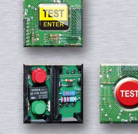
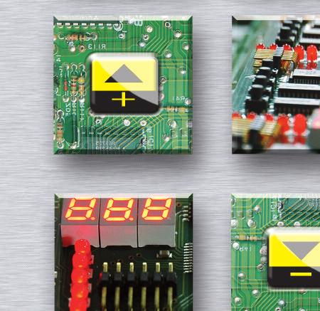
4 HRI-R40 series HRI-R40W series FUNCTIONS AND OPERATORS - LEGEND contrel R [k Ω] Z [k Ω] T1 [ C] T2 [ C] I [A] insulation monitor HRI-R40 SET ALARM OUTPUT ERROR / RELAY LINK FAIL MIN / MAX + _ RESET TEST SET ENTER display for visualising under-control parameters degree and for visualising settings 2 green LED SET for indication of programming status 3 yellow LED ALARM for indication alarm for parameter s degree out-threshold 4 red LED OUTPUT RELAY for indication status of auxiliary relay output 5 red LED ERROR / LINK FAIL for indication alarm of internal failure, lack connection to under-control network, temperature s probe PT100 open or short circuit 6 red LED R for indication visualisation of insulation s resistance parameter; flashing light for out-threshold parameter 7 red LED Z for indication visualisation of insulation s impedance parameter; flashing light for out-threshold parameter. 8 red LED T1 for indication visualisation parameter of transformer s temperature; flashing light for out-threshold parameter. 9 red LED T2 for indication visualisation parameter of second sensor temperature; flashing light for out-threshold parameter. 10 red LED I for indication visualisation current of network parameter; flashing light for out-threshold parameter. 11 button +/- UP/DOWN for selecting parameter that has to be visualised, for regulating device s setting and for visualising maximum and minimum memorized degrees 12 button RESET / SET for entering device s programming, for stopping alarms and memorized degrees resetting 13 button TEST / ENTER for testing device and remote signalling panels and for confirming SETUP settings DIMENSIONS contrel insulation monitor HRI-R40 90 R [k Ω] Z [k Ω] T1 [ C] T2 [ C] I [A] SET ALARM OUTPUT RELAY MIN / MAX + _ RESET SET ERROR / LINK FAIL TEST ENTER HRI-R40 / HRI-R40W
5 HRI-R40 series HRI-R40W series ELECTRIC CHARACTERISTICS TYPE HRI-R40 HRI-R40W Auxiliary supply Frequency Self-consumption Unde-control network voltage Voltage's measure Current's measure Internal impedance for resistive measure Selectable trip threshold Visualisation Output Input Voltage of signal circuit Measure s method Insulation s test Working temperature Storing temperature Relative humidity Standard regulation Assembling according to DIN Dimensions Protection s degree Connections V ±20% Hz 5 VA V Hz 24 V 1 ma 200 kohm kohm (low insulation) hysteresis 10 % C (over-temperature) precision 2 % A (over-current) precision 2 % - delay 1 60 sec insulation and impedance s degree by three digits display kohm temperature s degree C (1st and 2nd probe) by display current s value A by display parameters configuration output status: - signalling alarms led - led of signalling output of active relays - led of failed insertion signalling for PR5 (max 5) panel + 1 contact NO-C-NC 5 A V low insulation, overload + option serial RS485 MODBUS-RTU from isolated network 230 Vac (insulation measure) 1st probe PT100 2 or 3 wires (temperature measure) C ±2% 2nd probe PT100 2 or 3 wires (temperature measure) (OPTIONAL) C ±2% CT (overload current measure max 5 A precision 2 % current transformer ratio selectable 1 40 < 24 Vdc signalling dc V ±20% Hz 5 VA V Hz 24 V 1 ma 200 kohm < 24 Vdc codified and varying signal 2.5 KV 60 sec C C MAX 90 % CEI-EN / CEI-EN / VDE 0413 part.8 / CEI 64.8/7-710 V2 IEC / VDE 0100 part.710 / UNE / CEI-EN snap on DIN rail 35 mm 6 modules DIN 17.5 mm IP50 frontal - IP20 case by screw terminals max 2.5 mm2 27
6 HRI-R40 series HRI-R40W series WIRING DIAGRAMS - LEGENDA HRI-R40AND HRI-R40W PT100 PT100 A B C PT2+A PT2+B PT2- PT1+A PT1+B PT1- CT-S2 CT-S1 R-NO R-C R-NC RS485 serial port (optional) Vaux:* 115V 115V AUX-L1 AUX-01 link fail check input 2 probe PT100 (o PTC) insulation check input 1 probe PT100 (o PTC) input 2 current TA.../5A remote check panel HRI-R40 relay aux output AUX-02 LF-PE LF-L VC-L VC-PE AUX-L2 TEST+ TEST- ACK ACUS OVER COM-P V-P FAULT remote panel PR COM-S F-S V-P ACUS ACK OVER FAULT COM-P TEST- TEST-S TEST+ auxiliary supply Vaux: 230 Vac PE S S TO OTHER REMOTE PANELS PR5 INSULATION TRANSFORMER L PC N INSULATED LINE (IT-M) LOAD AUXILIARY SUPPLY - TERMINALS supply s section is carried out with double input 115 V nominal for device supplying with 230 V, it is required to connect both sections in series for device supplying with 115 V, it is required to connect both sections in parallel LINK-FAIL MONITORING - TERMINALS 6-7 both terminals have to be connected between a isolated network s phase and unipotential node (PE) Maximum applicable voltage is 250 V (see insulation s monitoring) INSULATION S MONITORING - TERMINALS 8-9 both terminals have to be connected between centre tap of secondary transformer or a isolated network s phase and unipotential node (PE) Maximum applicable voltage is 230 Vca so single phase networks could have max voltage of 230 V, three phase networks three wires could have max voltage of 230 V phase-phase; but three phase networks four wires could have max voltage of 230 V phase-neutral REMOTE PANEL S CONNECTIONS PR5 - TERMINALS connections for linking to remote panels PR5, Max voltage on these conductors is 24 V SERIAL PORT RS485 (OPTIONAL) - TERMINALS terminals A-B (19-20) head to serial bus, terminal C (21) is a mass reference that could be connected to eventual screen of cable RS485 Standard protocol used is modbus-rtu, documented in a specific handbook [IM833-U] INPUT TEMPERATURE PROBE 2 (OPTIONAL) - TERMINALS connections for linking to a temperature s sensor - PT100 (EN 60751) or PTC (DIN 44081) sensor could be used. In case of PT100 probes three wires, it is required to connect compensation s conductor to the same terminal of correspondent conductor. In case of PTC, it is necessary external resistor of 120 ohm min 1/4 W INPUT TEMPERATURE PROBE 1 - TERMINALS connections for linking to a temperature s sensor - PT100 (EN 60751) or PTC (DIN 44081) sensor could be used. In case of PT100 probes three wires, it is required to connect compensation conductor to the same terminal of correspondent conductor. In case of PTC, it is necessary external resistor of 120 kohm min 1/4 W INPUT FOR CURRENT MEASURE - TERMINALS connection for external current transformer with secondary 5 A (current transformer ratio is programmable); if there is 3-phase network must be used the special adapter type TSA-03 for 3 current transformer to permit to monitor in the insulation relay the highest value of the 3-phase currents. Only the module of the current value is measured (i.e. it is not important S1-S2 connection sequence) OUTPUT AUXILIARY RELAY - TERMINALS switch contact free from voltage and with programmable functions. Contact s performance MAX 250 V 5 A resistive load
 and insulation s level.")
7 HRI-R22t series GENERAL HRI-R22t series The device has similar characteristics of previous model but it s more cheap and it has less functions. There is measuring signalling and it is able to verify temperature of insulation power transformer (1 PTC input with contact NO or NC directly supplied by device) and insulation s level. These inputs are available: for remote repeaters panels PR2 and PR2-t and 1 relay NO-C-NC, that is activate when fixed threshold (insulation and temperature) are over-ride. HRI-R22t has frontally a bar led for visualising insulation s level of device and eventual alarm s presence is visualised frontally by led. Testing button is available and it works for monitoring insulation s level preset with calibration on relay (for example, with 50 kohm calibration all the led with inferior limit of 50 kohm will light during the test). This button monitors eventual remote reply panels PR-5 (max 2 panels). FUNCTIONS AND OPERATORS - LEGEND 2 1 contrel TEST SET HRI-R22t insulation monitor ON ALARM Link Fail alarm 50 kω 100 kω 250 kω 500 kω 1MΩ >1 MΩ Temp TEST PUSHBUTTON 2 MICRO SWITCH for threshold set - turning the switch to right, corresponding insulation s resistance degree has to be digit, highest degree heads - with all the switches turned to left, fixed degree of 50 kohm doesn t change 3 LED signalling supplied relay 4 LED signalling pre-fixed insulation s threshold reached 5 LED signalling temperature s threshold reached 6 LED signalling relay connected correctly 7 LED signalling instant insulation s value of device, identified by lowest degree between active led 29
8 HRI-R22t series VERSIONS FOR MEDICAL USE ROOMS ELECTRIC CHARACTERISTICS 30 TYPE Auxiliary supply Frequency Self-consumption Unde-control network voltage Voltage's measure Current's measure Internal impedance for resistive measure Selectable trip threshold Visualisation Output Input Voltage of signal circuit Measure s method Insulation s test Working temperature Storing temperature Relative humidity Standard regulation Assembling according to DIN Dimensions Protection s degree Connections HRI-R22t 230 V ± 20% Hz 3 VA V Hz < 15 V < 0.6 ma 1 Mohm kohm (low insulation) by switches led of insulation value by led bar kohm led of signalling network s presence led of signalling low insulation led of signalling over-temperature led of failed insertion signalling for panel PR5 (max 2) total + 1 contact NO-C-NC 5 A V (low insulation) + 1 contact NO-C-NC 5 A V (over-temperature ) from isolated network 230 Vac (insulation measure) PTC probe (temperature measurement) < 24 Vdc signalling dc 2.5 kv 60 sec C C MAX 90 % CEI-EN / CEI-EN / VDE 0413 part.8 CEI 64.8/7-710 V2 / IEC / UNE / CEI-EN snap on DIN rail 35 mm 6 modules DIN 17.5 mm IP50 frontal - IP20 case by screw terminals max 2.5 mm2 DIMENSIONS contrel HRI-R22t insulation monitor TEST ON ALARM Link Fail 90 SET alarm Temp. 50 kω 100 kω 250 kω 500 kω 1MΩ >1 MΩ
9 HRI-R22t series WIRING DIAGRAMS - LEGEND HRI-R22t Vaux:* 230V link fail check remote check panel insulation check relay temperature output remote check panel input thermostat relay aux output remote panel PR AUX-L1 AUX-01 LF-L LF-PE VC-L VC-PE COM-P FAULT V-P R-NC R-NO R-C COM-S F-S V-P ACUS ACK OVER FAULT COM-P TEST- TEST-S TEST+ auxiliary supply Vaux: 230 Vac PE S S TO OTHER REMOTE PANELS PR5 L INSULATION TRANSFORMER PC INSULATED LINE (IT-M) LOAD N AUXILIARY SUPPLY - TERMINALS MONITORING INSULATION - TERMINALS 5-9 both terminals have to be connected between centre tap of secondary transformer or isolated network s phase and unipotential node (PE). Maximum voltage applicable is 230 Vca. Consequentially single phase networks could be maximum 230 V, three phase networks of three wires is 230 V phase-phase but three phase networks four wires is max 230 V phase-neutral CONNECTIONS FOR REMOTE PANELS PR5 - TERMINALS INPUT THERMAL PROBE - TERMINALS or PTC (DIN 44081) probe could be used AUXILIARY RELAY OUTPUT - TERMINALS contact in switch voltage-free with programmable functions. Contact s capacity 250 V 5 A resistive load

10 HRI-R24 series GENERAL HRI-R24 series For monitoring 24 V networks (scialytic lamps), monitor HRI-R24 is used. This is able to supply insulation s control adjustable by frontal potentiometer. Frontally there is also testing button for allowing the test of device s correct functionality and eventual remote repeaters panels. Outputs are available for remote repeaters panels PR-5 (max 2 panels). FUNCTIONS AND OPERATORS - LEGEND INSULATION HRI-R24 MONITORING 30 kω TRIP ON RESET TEST contrel 1 Potentiometer for regulating trip threshold 2 Button of manual resetting 3 Test pushbutton 4 LED signalling supplied relay 5 LED signalling pre-fixed threshold reached 32 DIMENSIONS INSULATION HRI-R24 MONITORING RESET 10 kω 50 TRIP ON TEST contrel 52,
11 HRI-R24 series ELECTRIC CHARACTERISTICS TYPE Auxiliary supply Frequency Self-consumption Unde-control network voltage Current's measure Internal impedance for resistive measure Internal impedance for resistive measure Visualisation Output Input Voltage of signal circuit Measure s method Insulation s test Working temperature Storing temperature Relative humidity Standard regulation Assembling according to DIN Dimensions Protection s degree Connections HRI-R24 24 Vdc/ac -20 % +10 % Hz 3 W 24 Vdc/ac Hz < 0.5 ma 50 kohm kohm (by potentiometer) led of signalling network s presence led of signalling low insulation for PR5 panel (max 2) from isolated network 240 Vac/dc (insulation measure) < 24 Vdc variation of polarity s potential 2.5 kv 60 sec C C MAX 90 % CEI-EN / CEI-EN / VDE 0413 part.8 CEI 64.8/7-710 V2 / IEC / UNE / CEI-EN snap on DIN rail 35 mm 3 modules DIN 17.5 mm IP50 frontal - IP20 case by screw terminals max 2.5 mm2 WIRING DIAGRAMS - LEGEND insulation check HRI-R24 remote panel PR V+ V- OUT-NO OUT-C OUT-NC PE COM-S F-S V-P ACUS ACK OVER FAULT COM-P TEST- TEST-S TEST+ 33 PE S S TO OTHER REMOTE PANELS PR5 L(+) N(-) INSULATED LINE 24V ca/cc LOAD INSULATION TRANSFORMER
.")
12 PR5 REPEATER PANELS GENERAL PR 5 Panels of remote signalling PR allow to give alarm signalling of insulation s monitoring devices HRI. HRI devices monitor permanently insulation s level and the overload of supply network in medical use rooms (IT- M networks). Signals of low insulation alarm and/or overload could be signalled in rooms supplied from network and by board, which incorporate signals with LED of active device and low insulation alarm (and overload, if it is forecasted). They have also an acoustic signaller incorporated, a test button and a button for stopping acoustic signal. Board is flush mounted universal box (E503) in order to be located in rooms supplied by under-control network. Maximum of repeater boards associable with HRI device is 2. PR5 remote signal panel network insulation control 4 6 TEST TEST PERIODICALLY ON OVERLOAD SILENCE FAULT 3 34 MODEL PR5 Repeater panel for HRI-R22t, HRI-R24, HRI-R40V, HRI-R40W (indication of low insulation alarm) green LED of signalling active device (voltage presence) red LED of sigalling overload or overtemperature yellow LED of sigalling FAILURE (low insulation) test button for testing functionality of HRI system and PR board internal buzzer internal buzzer space for notes
 green led NETWORK - red led ALARM of overload yellow led ALARM of FAILURE low insulation, acoustic signal test button -")
13 PR2-PR2t-PR4 REPEATER PANELS ELECTRIC CHARACTERISTICS Operative voltage Signallings Operators Working temperature Storing temperature Relative humidity Insulation test Connection type Protection's degree Mounting Weight Standard reference Vac/dc (from HRI device) green led NETWORK - red led ALARM of overload yellow led ALARM of FAILURE low insulation, acoustic signal test button - stopping acoustic signal button C C MAX 95 % 2.5 kvrms 50 Hz for 60 sec by screw terminals - wire section MAX 2.5 mm 2 IP 30 front panel - IP 20 case universal flush-mount box E503 approximately 200 g CEI-EN CEI-EN / VDE 0413 part.8 CEI 64.8/7-710 V2/ IEC / UNE CEI-EN ASSEMBLING PANEL S CONNECTIONS WIRING MOUNTING SEQUENCE DIMENSIONS 35 PR5 remote signal panel network insulation control TEST TEST PERIODICALLY ON 79 OVERLOAD SILENCE FAULT E503


14 EML-12S SERIAL REMOTE CONCENTRATOR FOR REMOTE MONITORING OF NETWORK S PARAMETERS GENERAL Serial remote concentrator is a device which allow remote monitoring of parameters originated from insulation s supervisors for medical use rooms HRI-R40 and HRI-R40W with serial output RS485. By serial communication RS485 Modbus-RTU protocol different supervisors are connected to concentrator EML-12S. Device could supply degrees of insulation and impedance s resistance, of network s temperature and current, and eventual alarm s presence with data-logger function. By its time, device could be connected to a PC and transmit different parameters gathered. It could also be connected to a remote visualisation panel with function of signalling alarms in network. HRI NETWORK MODELS EML-12 remote concentrator Vaux 24 Vdc/ac Devices HRI-R40 or HRI-R40W are connected to EML-12S concentrator by serial output RS485. Maximum 12 HRI devices could be connected HRI NETWORK HRI HRI HRI HRI HRI RS485MODBUS 36 RS485MODBUS RS485MODBUS contrel PC VISUAL DISPLAY
 OFF (offline). For every instrument it s possible to visualise last 4 intervened alarms.")
15 EML-12S SERIAL REMOTE CONCENTRATOR FOR REMOTE MONITORING OF NETWORK S PARAMETERS VISUALISATION For every device connected it s possible to visualise INSULATION S RESISTANCE, IMPEDANCE, TEMPERATURES AND CURRENTS. For every device connected it s possible to visualise instrument s status ON = (online) OFF (offline). For every instrument it s possible to visualise last 4 intervened alarms. EVENTS When there is an alarm, it s automatically visualised on display with indication of total alarms active in that moment. 37 MENU AND SETTINGS By menu, it s possible to set parameters as date and hour, language, number of connected devices and settings for serial communication.