Streamlining PCB Assembly and Test NPI with Shared Component Libraries
|
|
|
- Mildred Chapman
- 5 years ago
- Views:
Transcription
1 Streamlining PCB Assembly and Test NPI with Shared Component Libraries Julian Coates Mentor Graphics Wilsonville, Oregon Abstract PCB assembly designs become more complex year-on-year, yet early-stage form/fit compliance verification of all designedin components to the intended manufacturing processes remains a challenge. So long as librarians at the design and manufacturing levels continue to maintain their own local standards for component representation, there is no common representation in the design-to-manufacturing phase of the product lifecycle that can provide the basis for transfer of manufacturing process rules to the design level. A comprehensive methodology must be implemented for all component types, not just the minority which happen to conform to formal packaging standards, to successfully left-shift assembly and test DFM analysis to the design level and thus compress NPI cycle times. The elements of such a solution include implementing de-facto standards for package and pin-type classifications, as well as DFM analysis rules that are associated with these classifications and the intended manufacturing processes. The resulting solution enables the transfer of DFM rules from the manufacturing process expert to the design and NPI engineers on the design side responsible for verifying manufacturing-process compliance of new product designs. This paper will demonstrate the technological components of the working solution: the logic for deriving repeatable and standardized package and pin classifications from a common source of component physical-model content, the method for associating DFA and DFT rules to those classifications, and the transfer of those rules to separate DFM and NPI analysis tools elsewhere in the design-through-manufacturing chain resulting in a consistent DFM process across multiple design and manufacturing organizations. Following establishment of a common source of component definitions and classifications, rules-based generation of assembly-level machine libraries is enabled from the same source that drove the DFM process, resulting in right-first-time launch of a new product into the manufacturing process. Introduction The principles of lean manufacturing, getting it right first time, minimizing waste and unnecessary manual interaction, are all familiar and generally accepted as contributing factors toward cost reduction and quality maximization. In that context, this paper will examine two specific engineering-process aspects of introducing a new PCB design into assembly manufacturing and the technical barriers to be overcome to make the processes as lean as possible. The two engineering processes to be discussed are: 1. Performing design-for-assembly (DFA) verification on a new product design, as early as possible in the product lifecycle, and in any case before transferring the design into manufacturing. 2. Preparing assembly-line machine library content for fast set-up. Before getting into the technicalities of the two topics and how they are related, it is worth first considering the business environment of PCB manufacturing. It is now about 20 years since PCB assembly manufacturing began to be outsourced in a major way, with the resulting rapid growth of the now well-known EMS and contract manufacturers. Before the outsourcing revolution, when design and manufacturing operations were generally vertically integrated, it was common to see CAD/CAM engineering processes being set up and maintained by electronics OEMs, depending for their success on internally defined library standards, a specific and relatively narrow range of manufacturing processes, and plenty of inhouse proprietary software to link it all together. By contrast, today s challenge is to take full advantage of the outsourcing opportunity, the choice, the flexibility, and the cost-competitiveness, without losing the advantage through engineeringprocess inefficiencies related to discontinuities in CAD/CAM software, data flows, and libraries between the customer (the design organization) and the suppliers (the manufacturers). To make matters worse, the typical manufacturer of today will serve dozens, if not hundreds, of design-customers, and the design organization may use dozens of EMS providers. This many-to-many interface between design and manufacturing tends to drive engineering processes toward standardized lowest common denominator workflows that are relatively manual, error-prone, and slow. These workflows are certainly somewhat standard, but they are far from lean, in terms of minimizing waste and maximizing consistency through automation. The two engineering processes described in this paper are specifically designed to enable a high degree of productionportability between a product s design organization and multiple manufacturing facilities and processes. Portability of DFA Design for assembly DFA) refers to the dimensional analysis of a PCB design to check its compatibility with the intended manufacturing processes. Figure 1 shows illustrations of two specific DFA analysis checks: one checking the pin-to-pad


2 distances against the rules of the reflow process, the second checking component-to-component spacing against the accessrequirements of the rework process. The variety of rules typically scales with the range of intended assembly and test processes, as well as the number of component types or combinations of component types. Figure 1: Two DFA checks: pin-to-pad analysis (left), and component-spacing analysis (right). Now consider the DFA business process between a designer and a manufacturer, as illustrated in Figure 2. The designer has responsibility for the definition of the product, whereas the manufacturer is the owner of the manufacturing processes and the knowledge of their limitations relative to the characteristics of the products being manufactured. Figure 2: Outsourcing separation between design responsibility and manufacturing-process responsibility. The designer s interest is to design the product so it is optimally manufacturable by the widest range of manufacturing suppliers. To be as lean as possible, the DFA validation process should be carried out in one place, on the design side, before handing the product to the manufacturers for production. But unless there is a formal common language for defining the product-model and the rules to be applied, the DFA process cannot be left-shifted from the manufacturing level into the design domain.
3 Figure 3 shows a simple real-life example of what happens when the designer is looking at the product with the design library, and the manufacturer is looking at the product with the manufacturing library. The component is the same, but its modeling is different. On the design side, the library sizes the pin of the component according to the pad it is standing on, whereas the manufacturing library sizes the pin according to the actual pin that is part of the component that will actually be placed on the board. Any communication between the designer and the manufacturer about what is an acceptable pin-spacing is meaningless unless a common modeling of the component is supporting the discussion. The same applies to the DFA rules themselves, unless the rules have the same meaning at both ends of the DFA process, the process will bring incorrect results and be of no value. Figure 3: Outsourcing the need for a shared standard for component models. First Requirement The previous examples have shown how the models of the components must be standardized across the DFA workflow. The first assumption is that existing formal standards such as EIA, IPC, or JEDEC would meet the need. Assuming a reliable source of content could be found to deliver component models according to the standards, all mapped to their commercially purchasable part numbers, the standards approach would have had obvious benefits. However, we discovered, when examining the master parts lists of major DFA practitioners, barriers to a scalable solution based purely on the formal standards. a) There are PCB-mounted components that do not conform to a standard of any kind. Figure 4 shows several examples of commercially available components that cannot be described by the JEDEC standard.
4 Figure 4: Formal component-modeling standards do not cover all purchasable parts. b) We found examples where the component manufacturer may declare that the component conforms to a standard, but in reality some of the dimensions are outside the tolerances set by the standard. Figure 5 shows one such example where some of the dimensions are outside the limits set by JEDEC. The size of the deviations may be small, but they could be enough to cause DFA violations to slip through into manufacturing; and in any case, a component is either within tolerance of not. We found that, from a sample of some 20,000 component package models of chip-style components that you would expect to be modeled by JEDEC in the 0402 or 0603 range of categories, approximately 20% were impossible to map correctly to the standard as defined. Therefore, the standards designation is not enough; a full graphical representation of the component and its pins is required.
5 Figure 5a: According to JEDEC MO-236C, minimum component body height is 0.45 mm. Figure 5b: A commercial part, claiming to conform to JEDEC MO-236C, but actually does not conform. The second prevailing assumption, especially in the design community, is that the library of the PCB layout system should be used for the purpose of DFA. From the standpoint of the designer, such an idea has obvious attractions. But the design library fails the suitability test for four reasons. Firstly, design library content is not systematically constructed according to any level of standardization that is recognizable outside the boundaries of a specific design organization. The rules and meaning of the design library content is defined and owned by the librarian, and it is highly likely to be inconsistent with the library content from a library in another organization that is under the control of a different librarian. Secondly, the design library usually does not model the physical pin of the component at all, focusing instead on the component body outline and the related pad stacks; yet it is the relationship of the physical pin to the pads and solder mask openings that mainly determines the quality of the soldered joints that will be created in the manufacturing process. Thirdly, the design library component model is usually an approximation based on all alternative purchasable parts that may be placed there (according to the master parts list or AVL), thus it cannot be said to support the DFA analysis of any specific part that may be used in production. Fourthly, many design libraries contain multiple outlines for the component bodies, representing anything from the actual outline, to a keep-out box that will be used to enforce component spacing design rules. As a consequence, when the product model is output to manufacturing and especially in an outsourced manufacturing environment, it is not always clear what the component body outlines actually represent and thus which DFA rule-values to apply. Therefore, and as part of developing a portable DFA process, a dedicated library format was defined that provides a shared standard for the participants in the DFA workflow. The approach taken was to use the JEDEC classification system, but with extensions to give the granularity required to support the full range of DFA rules to be applied. The essential structure of the library is shown in Figure 6, showing how the linking of the component manufacturer and purchasable part number(s) to the component model comprises a classified name linked to the graphics of that particular model. Examples of component models are shown; the principle being that, whenever a different graphical model is required to fully represent the detail published in the component manufacturer s datasheet, a new unique classified name is generated.

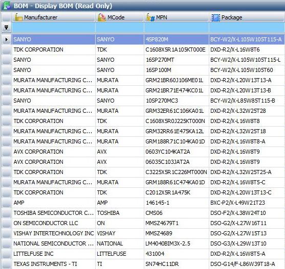
6 Figure 6: Cloud-based library structure linking purchasable parts to fixed-syntax graphical models. But it is not only the definition of the library structure and format that is essential to the solution, but also the availability of the content, as a service to the DFA engineers; the greater the extent to which the library can deliver the content for any particular PCB bill of materials (BOM), the greater the comprehensiveness of the DFA analysis that can be performed. After 15 years of building the content on behalf of DFA engineers around the world, there are now approximately 100,000 uniquely classified graphical models in the library mapped to upwards of 35 million purchasable part numbers. To date, there has not been a single instance of a PCB-mountable electronic component that cannot be modeled in the library for DFA purposes. Second Requirement The second major requirement to enable portability of the DFA process is to establish a standardized package- and pinclassification system in which the DFA analysis rules can be managed. The main challenge arises from the need for relevant spacing measurements between pairs of components of different classification. For example, the acceptable spacing between a small chip-resistor and an adjacent BGA will probably be different to the acceptable spacing between the BGA and a connector. Thus, the number of component-to-component rules can be proportional to the square of the number of different types of components in the library. Obviously, while it is necessary for the sake of DFA measurement accuracy to have available a number of unique component models on the order of 100,000 (as described in the previous section), to have 100,000 x 100,000 separate DFA rules to manage is obviously impracticable. The approach we took was to consult people who are using DFA technology to determine the maximum granularity of component package types and lead form types needed to ensure that the DFA analysis measurements are appropriate to the combinations of components on the PCB. After many years of gathering feedback, we have 17 different package types and 23 different lead-form classifications, which result in a range of DFA rules measured in the hundreds, not the billions that would result from using the library-level classifications to define the distinction between DFA rules. Figure 7 shows an example of a component model defined in the library as DAT-R16/M-L38W16T5_CPN081. This is the same syntax for unique definitions of the component models from the library definitions explained in the previous section. From this component model classification, the DFA software is able to automatically derive the package type as chip and the lead form as c-bend-wrap. The rules for defining these two type assignments are also shown in Figure 7.


7 Figure 7: Rules-based classification of package and lead form for DFA rules management. The advantage of deriving the type assignments within the DFA software is that as the DFA requirements of the industry evolve, the method for deriving the type assignments, and the connection of those assignments to the rules themselves, can be released via software updates without disturbing the library content that is at the root of the process. To illustrate the application of a DFA rule in the context of the type-assignments, Figure 8a shows a minimum heel-distance rule for components with lead forms of type c-bend-wrap. The rule calls for a minimum spacing of 5 mils, with 9 mils being the target for best yield. Figure 8b then shows the result of applying this specific rule to the relevant components; in this case, the minimum heel distance is actually negative, thus calling for either an engineering change to the land pattern, of a change of components supplier on the master parts list, or maybe both. Figure 8a: A DFA rule for minimum heel distance for a specific class of component.

8 Figure 8b: Application of a minimum heel-distance rule to a PCB assembly model. Third Requirement The third element of the portable DFA solution is a documented language of rules that can be transferred between manufacturer and designer for application as early as possible in the design process. By exporting the DFA rules that are proven by the manufacturer to represent the constraints of the manufacturing processes, they can then be transmitted to the design organization to run the complete DFA analysis process while the design is still taking shape and the cost of finding and fixing the manufacturability problems is so much lower than if left until later in the NPI cycle. In summary, Figure 9 illustrates how the portable DFA solution comprises the following multiple aspects that combine to make a working solution: A library of component models mapped to commercially purchasable part numbers. The library exists outside the internal networks of individual organizations, thus supporting the outsourced design-through-manufacturing flows of today. Availability of content in the library to describe the components listed in the bills-of-materials of the participating design and manufacturing organizations. Part-number coverage must run to the tens of millions, with rapid service to create missing content on demand to support scalable implementation by designers and manufacturers worldwide. DFA analysis software tools that can be used both in the context of design and manufacturing environments, with common functionality for the derivation of package and lead-form assignations, and a common DFA rules language.
9 Figure 9: Shared library content, classifications, and rules enable portable DFA analysis. Portability of Production between PCB Assembly Lines In the context of PCB assembly operations, by portability, we mean the ability to easily move the assembly of a specific PCB design from one assembly line to another or from one factory to another or rapid switching on a specific assembly line between the production of different products. The business drivers behind this are: Reduction in working capital resulting from lean production techniques that call for small lots of PCB assemblies to be produced according to downstream inventory demand signals. Supply-chain discontinuities making it impossible to continue production of a certain product, requiring fast switching to production of another product. Supply-chain flexibility for the product-owner to switch rapidly from one manufacturing service provider to another. Maintaining high asset utilization of the assembly lines themselves. Typically, the machinery that comprises the assembly line ties up the majority of the fixed-asset capital of the manufacturer so, just as airlines need to keep their planes in the air to earn money, the assembly manufacturers need to maximize the time when the assembly lines are assembly products. Assuming that component supply and machine availability are not limiting factors, the most important capability for addressing the above-mentioned business drivers is fast machine programming with all the data necessary to begin production of a new product. The primary burden here is the generation and management of the machine-level component libraries that determine how the different machines (placement, inspection, text) will treat each component on the PCB. As shown by Figure10, each different machine has its own library, which must contain definitions of the parts it will handle. A single assembly line may have five to six different machines all with their own libraries; across a large factory, the number of separately maintained libraries can run to the hundreds. Just consider the time involved, per new part, per machine. An industry average is to spend 15 minutes, per new part, per machine type, preparing and testing out the part data. If there are 20 new parts in a PCB that is new to that assembly line, that is five machines in the line. It will take 1,500 minutes (more than two hours) of machine down-time to prepare the machine libraries for that particular product. In an environment of lean manufacturing with small lot sizes, such set-up overheads can mean that the manufacturer spends more time with his assembly lines down than up and running.


10 Figure 10: There are as many machine-library standards as there are types of machines in the world. When we examined the nature of the parts data in the machine libraries we discovered that, with the exception of data that cannot be found in a component s datasheet such as color changes and markings that vary with lot code, the machine library content can all be derived from a standardized 2.5D model through the use of machine-dedicated rules. The flow for the solution, together with the requirements at each stage, is as follows. First Requirement The flow requires a source library for the component models that links back to the commercially purchasable part-numbers used in the supply chain. This enables transferability of a PCB product model between organizations and the use of a common component-model standard for deriving the machine-level library content for any assembly line or factory. Figure 11 shows links between component vendor name plus part number and the models in the same library as was described in the above discussion of portable DFA. Figure 11: Mapping purchasable component part numbers in the BOM to shared library content.


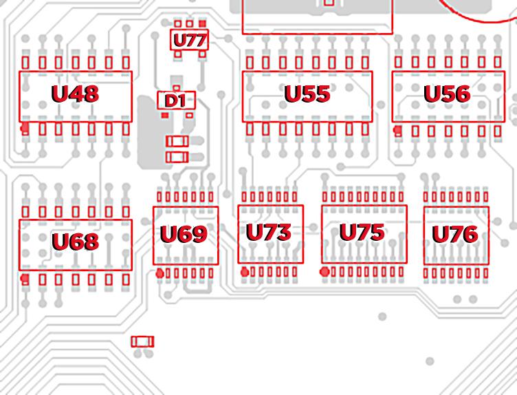
11 The result is that, in the context of any assembly line or factory, the model of the product to be assembled will be identical. Figure 12 shows an example of the PCB product model, after identification of the parts and integration of their models from the cloud-based library. You see the exact outlines of the component bodies, their physical pin contacts on the PCB, of course also linked to the data that is embedded in the component-model name itself. Figure 12: Component body and pin-contact models, integrated into the PCB product model. Second Requirement A classification system is required that can relate to any specific machine requirements to take the step from the general model of the part shown in the previous section to a machine-specific model of the part. After reviewing the libraries of the mainstream pick-and-place, AOI, AXI, and structural test machine vendors, we built a classification system as illustrated in Figure 13. From left to right, 24 component package classifications are shown for which machine-specific content can be derived. The rows in the table define the specific library content required by a particular widely used pick-and-place machine; the green cells are all instances where specific content is required for that machine to handle components of a particular classification. Thus, the purpose of the individual rows will vary according to the requirements of any particular machine, as will the definition of which classifications need each type of content (marked in green). Figure 13: Matrix linking machine-library component classes to machine-library content rules.

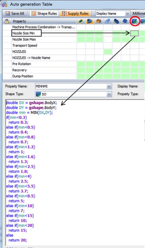
12 Each green square in the matrix can have its own unique derivation rule(s) to be applied when generating the content for that specific machine. To illustrate, we can take the example of a simple five-pin gullwing component. The component is automatically classified as SO, which requires an X body tolerance for the specific machine we are preparing the library for. The rule for calculating the X body tolerance for this particular machine is shown in Figure 14, with a plain English version written underneath. Figure 14: Automatic derivation of machine-specific library content (X-body tolerance). An example of a more complicated rule is shown in Figure 15 for the same component. In this example, the rule relates to the nozzle definition for the component. It illustrates the logic for selecting minimum nozzle size based on component body dimensions, for this particular machine.
13 Figure 15: Automatic derivation of machine-specific library content (nozzle diameter). Thus, by a process of creating and proving the rules that relate to the library requirements of the models of pick-and-place, AOI, AXI, test machine in use across the industry, and all those who use the machines worldwide can expect right-first-time set-up of their machine libraries without having to create and fine-tune the data on the machine itself. By a combination of a single globally accessible source-model for the components, plus the classification system dedicated to the needs of machinelevel libraries, and a library of rules at the machine-type level, a machine-library solution is created that can be applied at a level that runs above the individual machines, lines, and factories. Figure 16 shows the full flow of the solution, starting with BOM and model of the PCB assembly, through to the run-ready libraries at the individual machines.

14 Figure 16: Automatic library content-generation from one source, for multiple machine types. In effect, a unified on-demand library content service for any SMT assembly, inspection, and test line, worldwide. Production of a specific PCB assembly can be switched between lines of any machine combination within a matter of
15 minutes, bringing high flexibility in asset utilization and the opportunity to reduce production lot-sizes and thus levels of working capital. It opens the way for the full application of lean manufacturing in the supply-chain sense. Summary This paper describes a technological implementation of component libraries, classification systems, and rules that support DFA and assembly-line setup portability. The development has taken time because of a number of factors related to investment, time to gather and verify industry requirements, and the time required to establish library content of sufficient critical mass to meet the needs of the industry in general (tens of millions of parts). To be a working solution, multiple pieces of a puzzle had to be developed in parallel, including: 1. A globally available library that meets the requirements for DFA analysis and assembly line machines, loaded with content to match the many millions of parts in use by the design and manufacturing organizations. 2. A component classification system that meets the needs of DFA analysis. 3. A set of rules for DFA analysis, matched to the classification system, the values for which can be maintained by process engineers. 4. A component classification system that meets the needs of PCB assembly-line machine-library generation. 5. A set of rules for machine-level library generation that matches the classification system, which can be extended as new machines and component types emerge. 6. The software infrastructure and tools to realize the solution in the hands of PCB designers and manufacturers in thousands of locations worldwide, together with its on-going maintenance and upgrading according to developing industry processes and requirements. The forward roadmap is to continue the development of all the aspects described above, in parallel and according to industry requirements, and also to support additional PCB-related engineering processes that can take advantage of the same source library content so as to further reduce the per-task cost.
16 Streamlining PCB Assembly and Test NPI With Shared Component Libraries Julian Coates Director Mentor Graphics, Valor Division
17 Contents Outsourcing, effect on libraries Focus on portability of two processes 1. The portability problem:- DFA DFA solution 2. The portability problem:- Assembly-line libraries The assembly-line libraries solution Summary
18 Traditional (localized) manufacturing One to One or a Few to a Few Company-specific standards for engineering processes DESIGN MANUFACTURING
19 Modern manufacturing: Globalized Many-to-Many relationship between designers and manufacturers Consequence:- Engineering processes conform to the lowest common denominator DESIGN MANUFACTURING Focus: Libraries for DFA and the assembly & test process
20 The DFA portability problem Ideal lean scenario:

21 The DFA portability problem Without a shared process:

22 A selection of component package types not covered by JEDEC


23 Commercial parts conforming to JEDEC JEDEC minimum dimension example
24 Commercial parts conforming to JEDEC (Should be not less than 0.45mm..)
25 DFA-dedicated library structure and content-service:- ~100,000 package models Can describe any purchasable part

26 Rules-driven package-type and lead-form derivation

27 Example of DFA rule, according to classifications

28 Example of applying a DFA rule, according to component classification
29 Shared library, classifications and rules enabling portability of DFA
30 Modern manufacturing: Globalized Many-to-Many relationship between designers and manufacturers Consequence:- Engineering processes conform to the lowest common denominator DESIGN MANUFACTURING Focus: Libraries for DFA and the assembly & test process
31 The machine-library problem Multiple repeated tasks for the same parts:
32
33


34
35
36
37


38 Combined solution overview DFA classification rules DFA analysis rules Portable DFA Portable machine-library generation Machinelibrary classification rules Machinemodel rules Shared library (cloud-based)