APPENDIX A Drainage Design Report for Farmers and Cooks Branches APPENDIX B Drainage Design Report for Jackson and Audelia Branches
|
|
|
- Derrick Atkins
- 5 years ago
- Views:
Transcription
1
2 Table of Contents CHAPTER 1 - INTRODUCTION PURPOSE PROJECT LIMITS SCOPE CHAPTER 2 - DATA COLLECTION AS-BUILT PLANS EXISTING UTILITIES SURVEY TOPOGRAPHY PHOTOGRAPHS CHAPTER 3 - HYDRAULIC DESIGN MANUAL CHAPTER 4 - DRAINAGE AREA MAPS AND HYDROLOGY EXISTING CONDITIONS PROPOSED CONDITIONS CHAPTER 5 - TRUNK LINE ALTERNATIVE ANALYSIS ALTERNATIVE DEVELOPMENT TRUNK LINE ALTERNATIVES TRUNK LINE EVALUATION MATRIX CHAPTER 6 - PRELIMINARY HYDRAULIC DESIGN MINOR CULVERTS TRUNK LINES CHAPTER 7 - Valwood Improvement Authority CHAPTER 8 - BEST MANAGEMENT PRACTICES CHAPTER 9 - SCHEMATIC REVISIONS IH 635 Drainage Design Report i October 2006
3 APPENDICES APPENDIX A Drainage Design Report for Farmers and Cooks Branches APPENDIX B Drainage Design Report for Jackson and Audelia Branches EXHIBITS Description Number of Pages Exhibit 1 Location Map 1 Exhibit 2 Preliminary Utility Data 53 Exhibit 3 Existing Flow Patterns 8 Exhibit 4 Drainage Area Maps 17 Exhibit 5 Hydrologic and Hydraulic Data 17 Hydrologic Data 5 Hydraulic Data - Cross Culverts 2 Hydraulic Data - Trunk Lines 10 Exhibit 6 Alternative Trunk Line Locations 7 Trunk Line Evaluation Matrix 1 Alternative Typical Sections 6 Exhibit 7 Proposed Trunk Line Layouts 26 Exhibit 8 Proposed Trunk Line Profiles 26 Exhibit 9 Culvert Layouts 6 Exhibit 10 Wetlands Layouts 1 IH 635 Drainage Design Report ii October 2006
4 List of Tables Table 7.1 Frontage Road and Levee Elevations IH 635 Drainage Design Report iii October 2006
5 Introduction CHAPTER 1 - INTRODUCTION 1.1 PURPOSE The purpose of this report is to provide preliminary hydrologic analysis and hydraulic design for watersheds and drainage structures that impact the proposed IH 635 Freeway improvements between Luna Road to Skillman Street (referred to in this report as IH 635 corridor). Also included is IH 35E from Royal Lane to Valwood Parkway. The goals of this report are to provide consistent analysis and design based on the drainage criteria developed for the IH 635 corridor, determine the existing and proposed hydrology, develop preliminary sizes of major drainage cross structures, analyze major waterways that cross the IH 635 corridor, identify areas within the IH 635 corridor for use in best management practices, and make minor schematic revisions necessary to provide adequate drainage. This report is available through TxDOT to all project engineers. It is intended that this report be a reference for their design efforts and to avoid duplication of analysis and design contained herein. Exhibits for the main body of the report are located in a separately bound 11 x 17 document. Any design shown in these exhibits is preliminary and not for construction. 1.2 PROJECT LIMITS The approximate 21-mile project passes through the cities of Farmers Branch, Dallas, and Mesquite, and has been divided into two separate sections for the purposes of this study as illustrated by the project Location Map, Exhibit 1. The west section limits are from Luna Road to west of US 75. This section will consist of eight IH 635 mainlanes, four to six managed lanes, and the IH 635/IH 35E interchange. IH 35E limits extend from Royal Lane to Valwood Parkway. In addition, the west section will include the proposed managed lanes, box sections and mined tunnels. The major waterways located with the limits of the west section are: Cooks Branch, Farmers Branch and the Farmers Branch Tributary channel. The east section limits are from east of US 75 to US 80. The east section will consist of ten IH 635 mainlanes, two to four managed lanes, and the IH 635/IH 30 interchange. The major waterways located within the limits of the east section are: Jackson Branch, Audelia Branch, Dixon Branch, the East Prong, Long Branch, and South Mesquite Creek. IH 635 Drainage Design Report 1-1 October 2006
6 Introduction Because the IH 635/US 75 (High Five) interchange was under construction during this study, the section of IH 635 reconstructed with the High Five interchange project is not included. Hydraulic investigation of White Rock Creek was included in the High Five interchange design. The High Five interchange project reconstructed IH 635 from approximately 1,200-feet west of Coit Road to Greenville Avenue. This drainage design report has been developed for the west section of IH 635. In addition, a small portion of the east section (Greenville Avenue to Skillman Street) will be included in this report. This portion of the east section was added to this study because the limits of the proposed IH 635 managed lane system might extend east of US 75 to Skillman Street to enhance regional mobility. The remainder of the east section will be discussed in a separate drainage design report. 1.3 SCOPE This reports details the design methods and results of the hydrologic and hydraulic analyses performed within the west section IH 635 project. The drainage impacts caused by the proposed IH 635 improvements are identified and revisions to the schematic plans are recommended. The major waterways within the study limits (Cooks Branch, Farmers Branch, Farmers Branch Tributary, Jackson Branch and Audelia Branch) have been analyzed for the existing and proposed conditions. The areas available for best management practices are identified. In addition, an alternative analysis is provided for the proposed trunk line required to carry offsite drainage impacted by the proposed managed lane box sections. IH 635 Drainage Design Report 1-2 October 2006
7 Data Collection CHAPTER 2 - DATA COLLECTION 2.1 AS-BUILT PLANS As-built plans for the storm sewer systems, culverts and developments that impact the watersheds within the IH 635 corridor have been collected. This data was collected from the Texas Department of Transportation (TxDOT), the City of Dallas, the City of Farmers Branch, and various other agencies within the IH 635 corridor. The as-built data is available in electronic and hard copy format through TxDOT. 2.2 EXISTING UTILITIES TxDOT has completed low level Subsurface Utility Engineering (SUE) for this project. The available SUE data is shown in Exhibit 2. An electronic version of this data is also available through TxDOT. 2.3 SURVEY Survey data collected for the preliminary drainage study is available through TxDOT. The survey data consists of channel cross sections for the major waterways, cross culvert flowline elevations, minor culvert flowline elevations, various inlet and storm sewer flowline elevations, and field notes. 2.4 TOPOGRAPHY Existing topography and contours were obtained in electronic format from various sources. TxDOT provided approximately 1300 foot width along the IH 635 corridor of contours and background topography. The TxDOT topography also covers a narrow band along IH 35E, the Dallas North Tollway (DNT), and US 75. United States Geological Survey Maps (USGS) and North Texas Council of Governments (NCTCOG) were also obtained in digital format. 2.5 PHOTOGRAPHS Photographs of the major crossing culverts and various minor culverts are available through TxDOT. IH 635 Drainage Design Report 2-1 October 2006
8 Hydraulic Design Manual CHAPTER 3 - HYDRAULIC DESIGN MANUAL Prior to beginning the preliminary hydrologic and hydraulic study for the IH 635 corridor, the drainage criteria to be used in final design were determined. A drainage criteria manual was produced in conjunction with the TxDOT LBJ project office, the Dallas District and the Design Division. In addition to TxDOT contribution, input from the cities adjacent to the IH 635 corridor and other agencies within the corridor was compiled and incorporated into the manual. The following cities and agencies have reviewed and provided input to the drainage criteria for the IH 635 corridor: City of Dallas City of Farmers Branch City of Garland City of Mesquite Dallas Area Rapid Transit Dallas County IH 635 Drainage Design Report 3-1 October 2006
9 Drainage Area Maps and Hydrology CHAPTER 4 - DRAINAGE AREA MAPS AND HYDROLOGY 4.1 EXISTING CONDITIONS Between Luna Road and West of US 75, the existing IH 635 cross section provides four mainlanes with one concurrent flow HOV lane in each direction. The profile of these mainlanes undulates to form depressed sections between Marsh Lane and Rosser Road, at Welch Road, and between Monfort Drive and Preston Road. Locations on fill include a section between Luna Road and Harry Hines and overpasses at Denton Road, Josey Lane, Webb Chapel Road, Valley View Lane, Midway Road, the DNT, Hillcrest Road, and Park Central Drive. Elsewhere, the mainlanes follow surrounding natural ground. The IH 635 cross section also consists of two to three intermittent frontage roads that follow natural ground. Eastbound frontage roads proceed from Luna Road to the IH 35E southbound frontage road, from Josey Lane to Webb Chapel Road, and from Midway Road to US 75. Westbound frontage roads progress from Luna Road to the IH 35E southbound frontage road, from Harry Hines Boulevard to Marsh Lane, and from Midway Road to US 75. The IH 35E cross section consists of three mainlanes in each direction with concurrent flow HOV lanes. A reversible HOV lane is also located within the limits of the IH 635/IH 35E interchange. Frontage roads parallel the mainlanes from the IH 635 interchange to the north end of the project. Mainlanes and frontage roads follow natural ground except at mainlane fill sections south of IH 635 and at the Harry Hines Boulevard and Valley View Lane overpasses. A section of IH 635 between Luna Road and the IH 35E interchange is located adjacent to the Valwood Improvement Authority that is a flood control district. The southern portion of the district consists of levees along Farmers Branch Creek where they tie to the IH 635 frontage road fill and extend between the frontage road and mainlane fill. At the small sections between the mainlanes and frontage roads, gated outlet structures control flow and with the levees protect the district from the Standard Project Flood. Major drainage basins include Farmers Branch Creek, Rawhide Creek, Cooks Branch, Cottonwood Creek, White Rock Creek, Floyd Branch, Jackson Branch, and Audelia Branch. Farmers Branch Creek, Rawhide Creek and Cooks Branch are discussed in Appendix A. Jackson Branch and Audelia Branch are presented in Appendix B. The Cottonwood Creek and White Rock Creek drainage studies were completed with the High Five interchange by others. IH 635 Drainage Design Report 4-1 October 2006
10 Drainage Area Maps and Hydrology Exhibit 3 shows the general flow patterns and existing culvert locations. Exhibits 4 and 5 contain the existing conditions drainage area boundaries and hydrologic data sheets. Proceeding from west to east along IH 635, descriptions of the minor culvert drainage basins are given as follows: W1 and W2 Runoff flows east to west from the crest of Forest Lane. Storm sewer networks collect runoff from portions of the Highland Meadows residential neighborhood (Addition 1, 2 and 6), T-Mobile office park, Cinemark, the Office Depot shopping center, Motel 6, and other businesses that front Forest Lane. The Forest Lane trunk lines then tie to W25, which outfalls into an open channel between the IH 635 eastbound mainlanes and frontage road to combine with eastbound mainlane runoff originating at Josey Lane. The westbound mainlane drainage is carried to the downstream side of W25 through a series of open channels and a culvert that crosses beneath the eastbound exit ramp to Josey Lane. From W25 drainage is collected from the eastbound mainlanes and areas south of Forest Lane in a series of open channels, culverts, and the DART railroad bridge that run from W25 to the interchange between the eastbound mainlanes and Forest Lane. Runoff generally flows off of the mainlanes directly into the channel. Some mainlane underdrains and storm sewer outfall into this channel as well. The Forest Lane drainage is collected in small storm sewer systems that outfall into this open channel at W14, W17 and another unnamed culvert located between these two. At Harry Hines, W11 and W13 split the two so that a portion of the flow heads north through a series of culverts and open ditches to outfall on the west side of the IH 35E southbound mainlanes. The remainder continues west, downstream of W7 and W8 combines with runoff from the crest of Reeder Road and adjacent to Forest Lane, and runs through a series of open channels and culverts to outfall on the west side of the IH 35E southbound mainlanes. South of W3, IH 35E mainlane and southbound frontage road runoff flow into open channels that combine with the IH 635 north channel. North of Crown Road, IH 35E drainage flows into open channels that tie to the IH 635 south channel. The south channel flow is split just upstream of W2 to direct a portion of the flow to W1. The north channel flows to W1. On the west side of the IH 35E south bound frontage road, W1 and W2 drainage combine in an open channel that runs between the IH 635 west bound mainlanes and frontage road to outfall at the Farmers Branch Tributary. IH 635 Drainage Design Report 4-2 October 2006
11 Drainage Area Maps and Hydrology W3 Runoff flows from Northeast to Southwest beginning at Josey Lane. The westbound mainlane and frontage road runoff is collected through a series of open channels and culverts that outfall into W19. Between Cavendar s and Ford Road, offsite runoff is collected in separate systems that tie to W18. These offsite areas include two office parks East of Metro Boulevard, the Holiday Inn, a portion of an office park north of the Holiday Inn, Metro Boulevard from Cavendar s to Ford Road, and Ford Road from its crest. From Ford Road to W12, the flow is carried through a series of open channels, culverts, and a DART railroad bridge located between the westbound mainlanes and frontage road. Along this segment, runoff from the westbound mainlanes and frontage road flows directly into these channels. There are some mainlane underdrains (W24) that outfall into this channel as well. Offsite drainage from approximately 330 north of the frontage road is collected in side ditches and outfalls into the main channel through culverts crossing the frontage road. A concrete-lined open channel runs between W12 and W3. Within the interchange, the Westbound-to-Northbound direct connector, the IH 35E northbound mainlanes, the northbound frontage road, and the Harry Hines Boulevard crossing at IH 35E bound the W3 drainage basin. Some offsite from east of the frontage road enters the interchange by way of a small culvert crossing the northbound frontage road. W3 outfalls into a channel that drains to W75. W75 This basin collects the W3 flow and runoff from the IH 35E southbound mainlanes and frontage road by way of overland flow and open channels. Harry Hines, the southbound mainlanes and frontage road, and the channel between W3 and W75 bound this drainage basin. W75 outfalls into a mostly grass-lined open channel that heads south along the IH 35E southbound frontage road. At the IH 635 westbound frontage road, the channel turns west and parallels the frontage road. It combines with the Farmers Branch Tributary just upstream of the bridge. W69 This is a small basin that contains runoff from portions of the Office Depot shopping center and the crest of Josey Lane at Forest Lane. A storm sewer network collects runoff to a pipe that heads north and crosses IH 635 along the west side of Josey Lane. This system ties to the cross structures at Villa Creek. W27 Generally, runoff flows east to west. On the east side of Josey Lane, runoff flows directly into ditches between the eastbound IH 635 mainlanes and frontage roads. The IH 635 Drainage Design Report 4-3 October 2006
12 Drainage Area Maps and Hydrology westbound mainlane drainage flows into an open channel between the mainlanes and the frontage road. A storm sewer system collects the westbound frontage road runoff. At Josey Lane, all flow is collected into a storm sewer system that heads north along the east side of Josey to the cross structures at Villa Creek. W28 W28 drainage consists mostly of the area within the existing right-of-way. Runoff begins at Webb Chapel Road and heads west. The mainlane runoff flows into side ditches that outfall into culverts that parallel the mainlanes. Mostly curb inlets that tie to W28 capture frontage road drainage. A small portion of the area between the south right-of-way and the eastbound frontage road is captured by a culvert that crosses the frontage road and ties to the mainlane storm sewer system. The W28 pipe crosses IH 635 and heads north to tie to the Villa Creek channel. W68 Drainage flows from just West of the W31 culvert to Webb Chapel Road. Runoff from the IH 635 mainlanes and the eastbound frontage road flows directly into parallel ditches that outfall into area inlets that tie to a storm sewer system at Webb Chapel. The westbound frontage road drainage is collected by a closed system that ties to W28 at Webb Chapel. The W28 pipe runs north along the east side of Webb Chapel to the cross structures at Villa Creek. W31 The upper portion of W31 is on the south side of IH 635. Runoff flows from the Highland Meadows residential neighborhood and is collected by curb inlets on High Meadow Drive in the northwest section of the neighborhood. The storm sewer system heads north and outfalls into an open channel just upstream of the W31 cross culvert. Mostly, culverts W31 and W32 bound the west and east sides of the onsite area. Some eastbound mainlane drainage west of culvert W31 and some westbound mainlane and frontage road area east of culvert W32 drain to W31. Mainlane runoff flows directly into parallel open channels. The eastbound mainlane channel ties to the upstream headwall of culvert W31. The westbound mainlane channel drains to an area inlet that ties to the westbound frontage road storm sewer. Curb inlets and a closed storm sewer system collect the westbound frontage road drainage and outfall at the open junction box at culvert W31. The combined flow is then carried across the RHD Memorial Medical Center via a closed system to outfall at Villa Creek. IH 635 Drainage Design Report 4-4 October 2006
13 Drainage Area Maps and Hydrology W32 The W32 drainage basin includes large portions of onsite and offsite flow. The onsite flows from east to west, while most of the offsite approaches from the south. The east end begins at Valley View Lane and the south side of IH 635 where overland flow from the Hulark Apartment site collects at the northwest corner of the parking lot site and drains to the open channel that runs parallel to the eastbound mainlanes. The eastbound mainlane runoff flows directly into this channel that flows to the storm sewer system that drains the depressed section at Rosser Road. Approximately 1150 east of Rosser Road, the westbound mainlanes drain to this same system. Some north offsite flow from the Country Club Estates residential neighborhood and Rosser Road is collected via an area inlet in an open channel located between the top of slope of the depressed section and the north right-of-way. This area inlet ties to the depressed section storm sewer system. The mainlanes continue to drain to the storm sewer system until approximately 500 west of Marsh Lane. Portions of the eastbound Marsh entrance ramp and the westbound Marsh exit ramp also drain to this system. The storm sewer system outfalls on the south side of the eastbound mainlanes into an open channel where culvert W34 outfalls. The offsite drainage includes runoff from W34. The channel heads west until it reaches culvert W32. Along the channel reach, the eastbound mainlanes drain directly into the channel. Also, the runoff from portions of the Highland Meadows residential neighborhood collects in three separate closed systems that outfall in three locations in this channel. Culvert W32 outfalls on the north side of the westbound frontage roads where it joins with the W33A and W33B drainage. The flow continues across the RHD Memorial Medical Center property in a closed system to outfall at the beginning of Villa Creek. W33A W33A is an offsite drainage basin located on the north side of IH 635. From Ridgeoak Way to the south, most of the Town North Estates residential neighborhood drains to several drainage systems that tie to a pipe that runs parallel to IH 635 outside of the right-of-way. A small portion of overland flow near Templeton and Morningstar is collected in an open 7 x3 box. These systems tie to a junction box that joins W33A with W33B. This box outfalls into an open channel that runs parallel to the westbound frontage road. The channel ends at the downstream side of culvert W32. W33B The basin is located along the north side of IH 635 between the Joe Ratcliff Walkway and Rosser Road. West of Rosser Road, offsite from the Country Club IH 635 Drainage Design Report 4-5 October 2006
14 Drainage Area Maps and Hydrology Estates residential neighborhood flows to area inlets via the alleyway located between the neighborhood and the north right-of-way. A sliver of the onsite between Marsh and Rosser drains to a ditch between a berm on the top of slope of the westbound mainlanes and the north right-of-way. These inlets drain to a closed system to which a section of Marsh Lane located between Clubway Lane and the north side of IH 635 drains. From approximately 240 east of the Joe Ratcliff Walkway to Marsh, the westbound frontage drains to this system. Between the walkway and approximately 520 west of Marsh, the westbound mainlanes are collected by this same system. The closed system continues west to tie to a junction box that joins it with W33A. W34 W34 includes mostly offsite area that begins east of Marsh Lane. A storm sewer system collects runoff from the Meadow Park residential neighborhood and crosses Marsh Lane. At this point, it joins with the Marsh Lane system that collects runoff from a portion of the eastbound Marsh entrance ramp and area along Marsh Lane from IH 635 to High Meadow Drive. The system heads northwest and outfalls in the IH 635 south channel just west of the eastbound Marsh Lane exit ramp. W66 This is a very small basin that collects the eastbound mainlane and frontage road runoff from approximately 400 west of Valley View to Valley View. Mainlane runoff flows to an open channel that drains to an area inlet. Curb inlets collect the frontage road and Valley View drainage. The pipe crosses to the north side and joins with an offsite, closed system at the Valley View Market shopping center. W39 Within the right-of-way the high points for the frontage roads are Valley View Lane and Welch Road. The mainlane high points are Valley View Lane and approximately 2100 east of Midway Road. The eastbound mainlanes and frontage road drainage is collected predominantly in open channels and short storm sewer systems that outfall into open channels. West of Midway, the westbound mainlanes drain to an open channel, while east of Midway runoff is collected by inlets along the inside shoulder. These inlets either outfall to the open channel or tie to storm sewer located between the westbound mainlanes and frontage road. The upper reach of the offsite drainage is on the south side IH 635. East of Midway Road, runoff flows from residential areas and office parks into offsite storm sewer systems that outfall into an open channel that flows west between the eastbound mainlanes and frontage road. Storm sewer IH 635 Drainage Design Report 4-6 October 2006
15 Drainage Area Maps and Hydrology along Midway collects the roadway and adjacent shopping center drainage east and west of Midway and ties to culvert W39. The channels along the eastbound side drain toward Midway and outfall to storm sewer that ties to culvert W39. The channel along the westbound side east of Midway ties to culvert W39, but the channel west of Midway drains to culvert W36. Culvert W39 crosses IH 635 to the north to tie to W36, which is a closed system that runs north through the Wal-Mart parking lot. W67 This is a small onsite culvert that collects the depressed mainlane section at Welch Road. The culvert crosses from the north to the south and ties to a trunk line that combines with eastbound frontage road drainage and heads east toward the Dallas North Tollway. The trunk line outfalls in a channel approximately 170 upstream of culvert W45. W44 A large offsite area drains from the north towards IH 635. An offsite storm sewer network collects runoff from the Farmers Branch office park and outfalls into an open depression just upstream of W44. West of the W44 culvert, the westbound frontage runoff flows from Welch Road in an open channel that ties to culvert W42 located beneath the westbound entrance ramp. This culvert outfalls at the same location as the north offsite drainage. From the mainlane crest approximately 730 east of Welch Road, the westbound mainlane runoff is collected by inlets on the outside shoulders that outfall individually to the same channels/culverts as the frontage road does. East of the W44 culvert from the high point at the DNT, the westbound mainlanes drain to an inlet that ties directly to W44. Runoff from the westbound collector road and the frontage road flows off the pavement into the depression just upstream of W44. W44 crosses the IH 635 mainlanes from north to south and outfalls into an open channel that drains to W45. W45 This basin collects flow from W44 and the trunk line that runs between the eastbound mainlanes and frontage road from W67. It also collects runoff from the eastbound mainlanes from the mainlane crest. This mainlane runoff is collected by inlets in the shoulder that outfall into the open channel between the mainlanes and the frontage road. Culvert W43 located beneath the eastbound exit ramp carries it to the open channel that runs between W44 and W45. From the crest at the DNT, eastbound mainlane drainage and portions of the frontage road drainage runoff directly into the IH 635 Drainage Design Report 4-7 October 2006
16 Drainage Area Maps and Hydrology W44-W45 channel. Some the south side DNT drainage ties to culvert W45. W45 conveys the flow to the east side of the DNT at the beginning of Bachman Branch. W51 Offsite drainage flows from the north to IH 635 through offsite storm sewer systems that tie to the upstream end of the W51 culvert. The drainage includes the Dallas Galleria, the Chevrolet dealer, and portions of the Valley View Mall site. Onsite, the westbound mainlanes between the crest at the DNT and the crest approximately 810 west of Montfort Drive drain to open channels that connect to storm sewer that tie to W51. Between the DNT and west of Preston Road, the westbound frontage road runoff collects in a storm sewer/open channel system that ties to W51 on the north side of IH 635. W51 crosses IH 635 and outfalls into a short channel that ties to W50. W50 W50 collects W51 flow and eastbound mainlane runoff between the DNT and where the North DNT to East IH 635 ramp ties to the mainlanes. Culvert W50 crosses the above ramp and the eastbound frontage road to outfall at the upstream end of Bachman Branch. W52 This basin includes the runoff from the eastbound frontage road between the DNT and Preston Road. Some south offsite flow between Noel Road and Spurling Road drains to the eastbound frontage road. The frontage road drainage consists of a mostly closed system that ties to the mainlane system. The east boundary for the mainlanes is approximately 830 west of Preston road. For the west boundary, the North DNT to East IH 635 ramp tie-in bounds the eastbound mainlane drainage, and the crest approximately 730 west of Montfort bounds the westbound mainlane drainage. Mainlane runoff is in a closed system that outfalls at the upstream end of Bachman Branch. Bachman Branch runs through a parking lot bridge and connects to a system that crosses the DNT at Harvest Hill. This system outfalls in a channel on the Jesuit High School property. W55 This drainage basin includes the westbound mainlanes and frontage road runoff between the W51 and W52 east boundary to the east side of the W55 culvert. Flow runs off the westbound mainlanes directly into an open ditch between the mainlanes and the frontage road. The westbound frontage road runoff is collected in storm sewer near Preston Road that ties to parallel culvert W54. W54 carries westbound mainlane and IH 635 Drainage Design Report 4-8 October 2006
17 Drainage Area Maps and Hydrology frontage drainage from the west side of Preston to the east side and outfalls into an open channel. Flow from W56 outfalls into this channel as well. W55 crosses the Denny s parking lot and outfalls into an open ditch in the Prestonshire residential neighborhood. W56 W56 collects south runoff from Preston Road and adjacent businesses including the Mobil gas station and portions of the North Dallas Bank lot. Onsite drainage includes roadway drainage between the W51 and W52 boundaries and where the W56 culvert crosses. Flow runs off the eastbound mainlanes directly into and open ditch between the mainlanes and the frontage road. The eastbound frontage road runoff is collected in storm sewer near Preston Road that ties to parallel culvert W53. This culvert carries eastbound mainlane and frontage drainage from the west side of Preston to the east side and outfalls into an open channel. Flow from W57 outfalls into this channel as well. W56 crosses the mainlanes to the north and runoff flows to W55. W57 - Offsite drainage is collected via offsite storm sewer and overland flow that outfall into an open channel upstream of W57. This boundary is approximately 630 south of the eastbound frontage road. Culvert W57 crosses the eastbound frontage road and outfalls upstream of W56. W63 W56 and Hillcrest Road bound the onsite drainage. Roadway drainage is collected in small storm sewer systems and discharged into the parallel ditches between the mainlanes and frontage roads. A series of open channels and culverts carry the runoff to culvert W63. A large offsite area drains from the south and is collected in the eastbound systems. There are small offsite systems that outfall at Hughes Lane and Hillcrest Plaza. The majority of the flow is carried in a tributary of White Rock Creek that enters W63 upstream of the eastbound frontage road. W63 crosses IH 635 and outfalls just north of the westbound frontage road. Proceeding from south to north along, IH 35E descriptions of the minor culvert drainage basins are given as follows: W70-73 This basin flows from east to west. Offsite flow is collected in closed storm sewer systems along Valley View Lane and Pike Street that tie to the northbound frontage road system. An offsite open channel north of Valley View outfalls into one of IH 635 Drainage Design Report 4-9 October 2006
18 Drainage Area Maps and Hydrology the culverts crossing IH 35E. Northbound frontage road drainage between Pike and Jett flows to this system. Flow is carried across IH 35E through four separate structures that connect at different locations to a pipe that runs north on the west side of the southbound frontage road. Southbound frontage road and adjacent parking lots between Valley View and Havenhurst Road drain to this pipe. The network turns west midway between Valley View and Havenhurst to outfall east of the BNSF railroad. W74 Offsite drainage systems collect drainage from Dennis Lane to IH 35E. A closed pipe runs parallel to Havenhurst along the north side to tie to W74. All onsite runoff is collected in closed systems. Runoff from the northbound frontage road is collected between Jett and Havenhurst. A small of amount of mainlane drainage between Valley View and Havenhurst and of southbound frontage road in the Havenhurst area is collected into the W74 basin. W74 ties to an off site pipe that runs west to Branch View Lane. 4.2 PROPOSED CONDITIONS The proposed improvements for the west section as described in Section 1.2 significantly impact the drainage patterns within the right-of-way. Proposed drainage boundaries are shown on the Drainage Area Maps given in Exhibit 4. The managed lane box sections and portions of the mainlane profile cut through many of the existing cross structures, while others outfall to considerably undersized closed systems. Only a few of the existing structures may be utilized, and many require new trunk lines. Along IH 635 and west of the DNT, drainage is diverted to the IH 35E interchange, and those east of the DNT are diverted to White Rock Creek. On IH 35E from Valley View to Cooks, portions of the flow are diverted to Cooks Branch. The major drainage basins (Farmers Branch, Farmers Branch Tributary, and Cooks Branch) are discussed in Appendix A, and Jackson Branch and Audelia are described in Appendix B. Proceeding from west to east along IH 635, descriptions of the minor drainage basins are given as follows: W1 and W2 This basin will drain the same as the existing conditions plus flow from basins draining to W3, W27, W28, W31, W32, W33A, W33B, W39, W67, W68, and W69. Three large trunk lines will carry flow from the subbasins respective entrance points into the systems and will outfall west of Harry Hines Boulevard in the IH 35E IH 635 Drainage Design Report 4-10 October 2006
19 Drainage Area Maps and Hydrology interchange into a combination of open channels and wetland areas. For the trunk line plan, refer to Exhibit 5, Proposed Trunk Line Layout, sheet 4 of 26. A proposed culvert beneath the IH 35E mainlanes will convey the flow to the west side of the mainlanes. Then, the flow will be split in the wetlands area and directed to the proposed W1 and W2 culverts. W1 and W2 will be drained to the Farmers Branch Tributary through a series of open channels and culverts between the mainlanes and frontage roads on the eastbound and westbound sides. W3 The new basin will drain all westbound frontage road drainage from the IH 35E interchange to Rosser Road and approximately the same interchange area as existing. Offsite flow will include those areas drained in the existing conditions and W33A. A redesigned open channel between Harry Hines and IH 35E will carry the flow to the extended W3 culvert. The flow will be diverted to the south between the southbound mainlanes and frontage road in an open channel/wetland area to the new W1 culvert. W75 Runoff originating in the W75 basin will be diverted to the same channel as downstream of W3. The W75 culverts may be removed and the channel downstream of W75 may be abandoned. W69 The eastbound frontage road trunk line will capture this basin and convey it to the IH 35E interchange, as described later. More detailed analysis may allow some of the eastbound frontage road and offsite runoff to be directed to the system downstream of W69 instead of the westbound frontage road trunk line. W27 The mainlane trunk lines will capture the mainlane drainage and convey it to the IH 35E interchange. The westbound frontage road trunk line will capture the westbound frontage road flow and convey it to W3. Similar to W69, detailed analysis may show that portions of the westbound frontage road runoff may be directed to the downstream Josey Lane system. W28 The managed lane box sections cut through culvert W28. Therefore, all drainage will be diverted through the proposed trunk lines. The mainlane trunk line will handle the mainlanes, and the frontage road trunk lines will take their respective frontage road drainage. IH 635 Drainage Design Report 4-11 October 2006
20 Drainage Area Maps and Hydrology W68 Similar to W28, the managed lane box sections cross W68 making it unusable to the westbound frontage road and the mainlanes. Mainlane runoff will drain to the mainlane trunk line, and frontage road runoff will flow into their respective trunk lines. Although the current design on the westbound frontage road will not allow its low point to drain to the system downstream of W68, some of the frontage road flow may be directed to the outfall of W68 when further studied. W31 Because the existing culvert does not have adequate clearance below the proposed managed lane box sections, the trunk lines will convey the roadway runoff. The eastbound frontage road trunk line will convey the offsite entering from the south. Upon further analysis, portions of the westbound frontage road may be directed to the system downstream of W31. W32 Due to the managed lane box section, mainlane and frontage road drainage will be directed to their respective trunk lines. W32 s offsite and W34 s storm sewer systems will tie-in to the eastbound frontage road trunk. The W33A drainage will tie to the westbound frontage road trunk. Because the westbound managed lane box section alignment allows for space between it and the right-of-way, W33A and portions of the westbound frontage road may drain to the system downstream of W32. Preliminary analysis shows downstream system has limited capacity and requires further analysis. W33A and W34 The drainage patterns to the right-of-way remain the same. Within the right-of-way, the conveyance is as described for W32. W33B The westbound mainlane runoff drains to the mainlane trunk line. The westbound frontage road and offsite area drain to the westbound trunk line. W66 All drainage will be conveyed in the proposed trunk lines. W39 - The offsite drainage patterns to the south right-of-way remain in their existing configuration. Offsite storm sewer systems at Midway and east of Midway will tie to the eastbound frontage road trunk line. Once within the right-of-way the drainage is conveyed through the trunk lines to the west. IH 635 Drainage Design Report 4-12 October 2006
21 Drainage Area Maps and Hydrology W67 Because the managed lane section cuts through the existing culvert, all runoff to the west of Welch Road is collected in the roadway trunk lines. East of Welch, where the managed lane section is in a bored tunnel, the mainlanes would drain to a new cross structure that would tie to a trunk line system that drains to W45, as in existing conditions. Upon further study, some of the mainlanes west of Welch may tie to the new W67 as well. The mainlane trunk line heading west was conservatively designed to handle all of the mainlane runoff west of Welch. W44 Drainage patterns are very similar to the existing conditions. A small decrease in the amount of mainlane drainage would exist because the high point has been moved. W51 As with W44, drainage patterns are similar to the existing conditions except that the basin size is increased due to the move of the high point on the westbound mainlanes to the east. W45 and W50 The runoff drains as in existing conditions. W52 The drainage patterns are similar to existing patterns. The total area is reduced due to the westbound managed lane box section. The depth of the managed lanes forces them to have their own trunk system. W55 Because the existing culvert is undersized, water pools within the channel between the westbound mainlanes and frontage road. Beginning approximately 1000 west of Preston Road, a trunk line will convey the westbound frontage road drainage to White Rock Creek. Some of the westbound frontage road drainage may tie to this culvert upon further analysis, but the downstream system is limited and outfalls into a residential area. W56 The managed lane box sections eliminate the cross culvert. The proposed mainlanes drain to a trunk line that outfalls at White Rock Creek. W57 Offsite drainage patterns will remain the same, but once within the right-of-way an eastbound frontage road trunk line takes all offsite and eastbound frontage road runoff to White Rock Creek. IH 635 Drainage Design Report 4-13 October 2006
22 Drainage Area Maps and Hydrology W63 All runoff drains to the trunk lines that begin at Preston Road. Due to concerns about the existing conditions of the downstream creek and the close proximity to residential areas, the flow was rerouted. Further detailed analysis may allow for some flow to be conveyed to this creek and the trunk line sizes reduced. Because the existing culvert works with the proposed schematic except the need for upstream extension, it may be utilized. Proceeding from south to north along, IH 35E descriptions of the proposed minor culvert drainage basins are given as follows: W70-73 Offsite runoff follows the same pattern as existing. The existing conglomerate of cross culverts within the right-of-way will be replaced with one cross culvert and will tie to the existing system west of the southbound frontage road. The Valley View Lane and Pike Street closed storm sewer systems will tie to a trunk line that ties to the new culvert. A small area in the northeast corner of Valley View Lane and the northbound frontage road will drain to the same trunk line. Portions of the northbound and southbound frontage roads will drain to the proposed culvert. Because the downstream system is undersized, our analysis assumes that this trunk line will extend north along the northbound frontage road system and will continue to convey the remainder of the runoff to Cooks Branch. A portion of this runoff could be redirected to Farmers Branch Creek upon further study. W74 Because the receiving system is under sized, runoff will be divided. A juction box will connect the offsite drainage system to a proposed cross culvert and the proposed W70-73 trunk line. Roadway runoff will drain to both the cross culvert and the trunk line. Detailed analysis will allow a more comprehensive division of flow. Because the entire corridor is fully developed, runoff rates will be similar to those in the existing conditions. Only slight increases exist in some locations due to the conversion of grass-line open channel systems to closed systems located within the right-of-way. Proposed drainage systems and roadways should consider the VIA s levee system. The levees and gated outlet structures must operate as they did in existing conditions. IH 635 Drainage Design Report 4-14 October 2006
23 Drainage Area Maps and Hydrology The mainlane, ramp and frontage road profiles should be designed to protect against the Standard Project Flood (SPF) event with 1 of freeboard, which is approximately 443 feet and feet on the downstream and upstream sides of IH 635, respectively. More discussion is included in Chapter 7. IH 635 Drainage Design Report 4-15 October 2006
24 Trunk Line Alternative Analysis CHAPTER 5 - TRUNK LINE ALTERNATIVE ANALYSIS 5.1 ALTERNATIVE DEVELOPMENT As shown in the hydrology section of this report, offsite storm runoff generally flows from south to north within the limits of the proposed managed lane box sections. The runoff is collected in ditches and storm sewer systems that parallel IH 635 and cross the corridor through several cross drainage structures. The schematic locations of the proposed managed lane box sections dictate that these cross drainage structures be removed. The alternative analysis presented in this report is based primarily on the southern trunk line system because of the amount of offsite flow entering the IH 635 corridor from the south. Also, the trunk line to be located along the north right-of-way will be smaller and have less lateral restrictions based on the current IH 635 Schematic. Positive and negative attributes for the northern trunk line will be similar to the southern trunk line. The alternatives were evaluated for redirecting the offsite storm flow to the Farmers Branch Tributary and White Rock Creek. The proposed trunk line located west of the DNT will outfall into the IH 35E interchange. The proposed trunk line located east of the DNT will outfall into White Rock Creek. These trunk lines alter the path that storm flow takes to the outfall waterways but do not redirect runoff to other drainage basins. The trunk line analysis presented in this section was developed primarily on providing alternatives that have minimal impact to the current IH 635 Schematic plans. However, two alternatives will have medium to high impacts to the current managed lane box section alignments. The intent of this analysis is to provide the design Engineer with information that can be used to develop the final location of the trunk lines required along the corridor. The main alternatives are presented along with an evaluation matrix in the following sections. 5.2 TRUNK LINE ALTERNATIVES Six trunk line alternatives have been developed for redirecting onsite and offsite storm flow within the Farmers Branch Creek and White Rock Creek drainage basins. In addition to collecting offsite storm flow, the trunk line is intended to collect the storm drainage from the adjacent frontage roads. A description of each alternative along with positive and negative attributes of each option are presented below: IH 635 Drainage Design Report 5-1 October 2006
25 Trunk Line Alternative Analysis Alternative 1 This alternative consists of locating the trunk line south of the eastbound managed lane box section. Locating the trunk line south of the managed lane box section allows the trunk line to be constructed at a higher elevation than would otherwise be possible. This location also allows the trunk line to be constructed prior to the construction of the managed lane box sections and provide adequate drainage before blocking flow to the existing cross drainage structures. Where the managed lane box section is offset from the eastbound frontage road, the trunk line is located below the frontage road. When the managed lane box section is located below the eastbound frontage road, the trunk line is shifted south. Based on the right-of-way shown in the current IH 635 schematic, the trunk line will located outside the right-of-way approximately between Webb Chapel Road and Rosser Road. In this area, the trunk line may be located below the alleyway of the residential development adjacent to the IH 635 corridor. The outfall for this alternative will be in the IH 635/IH 35E interchange area. The storm flow will be carried in open ditch systems from the interchange to the Farmers Branch Tributary. A list of the positive and negative attributes for this alternative is shown below. Exhibit 6 shows the cross sectional location of the trunk line for Alternative 1. Positive Attributes: No impact to the current schematic managed lane box section alignment. Minimal impact to IH 635 during trunk line and managed lane box section construction. Reduces flow to Villa Creek north of IH 635. Because this channel is under sized, reducing the flow to Villa Creek is favorable to the City of Farmers Branch. Best management practice areas located within the IH635/IH35 Interchange may be used. Allows for more traditional lateral connections to the trunk line from offsite and the eastbound frontage road storm sewer systems. Minimizes excavation quantities. Negative Attributes: Requires easements to place the trunk line in the private alleyway. May be more difficult to provide emergency egress from the managed lane box sections. Narrow alleyway limits the trunk line width and produces a less efficient trunk line design. IH 635 Drainage Design Report 5-2 October 2006
26 Trunk Line Alternative Analysis Alternative 2 The trunk line for this alternative is located in the same position as Alternative 1. However, periodic cross culverts are utilized to reduce the size of the trunk line and minimize the amount of drainage easement required. Because periodic cross culverts are used, the vertical alignment of the managed lane box sections must be modified. In addition, the managed lane box sections must be covered in areas that are currently designed as open or depressed sections. A list of the positive and negative attributes for this alternative is shown below. Exhibit 6 shows the cross sectional location of the trunk line for Alternative 2. Positive Attributes: Minimal impact to the current schematic managed lane box section alignment. Minimal impact to IH 635 during trunk line and managed lane box section construction. Best management practice areas located within the IH635/IH35 Interchange may be used. Allows for more traditional lateral connections to the trunk line from offsite and the eastbound frontage road storm sewer systems. Minimizes excavation quantities. Negative Attributes: Requires easements to place the trunk line in the private alleyway. May be more difficult to provide emergency egress from the managed lane box sections. Narrow alleyway limits the trunk line width and produces a less efficient trunk line design. Alternative 3 This alternative combines the offsite runoff with mainlane and frontage road runoff in a large trunk line located under the IH 635 mainlanes. This alternative will result in essentially a large storm sewer tunnel with a diameter of approximately 20-feet. This alternative will also require that the trunk line is located at an elevation below the managed lane box sections. The lower elevation is required so that the frontage road storm sewer systems are able to periodically tie into the main trunk line. Because the trunk line for this alternative is at a lower elevation, it will not be able to outfall in the IH 635/IH 35E interchange area. This trunk line will outfall at the Farmers Branch Tributary. A list of the positive and negative attributes for this alternative is shown below. Exhibit 6 shows the cross sectional location of the trunk line for Alternative 3. IH 635 Drainage Design Report 5-3 October 2006
27 Trunk Line Alternative Analysis Positive Attributes: Minimal impact to the current schematic managed lane box section alignment. Most drainage structures remain in within the right-of-way. Reduces flow to Villa Creek north of IH 635. Because this existing channel is under sized, reducing the flow to Villa Creek is favorable to the City of Farmers Branch. Negative Attributes: Disrupts IH 635 mainlane traffic during construction of drainage tunnel. May be more difficult to provide emergency egress using managed lane box section to managed lane box section connections. Best management practice areas cannot be located within the IH 635/IH 35E Interchange. Lateral connections to the main trunk line are more complicated. Poor soils increase construction difficulties and cost. Alternative 4 The managed lane box sections are shifted to the area below the IH 635 mainlanes in this alternative. The trunk line can then be located at a higher elevation below the frontage road. In this alternative it was assumed that the managed lane box sections are shifted completely below the IH 635 mainlanes in order to maintain the managed lane entrance and exit ramps near Webb Chapel Road and Marsh Lane. If these ramps were removed, the managed lane box section would not be shifted completely below the mainlanes and the impacts to IH 635 traffic would be significantly reduced. Placing the managed lane box sections entirely below the mainlanes will require mainlane traffic to be shifted away from box section construction. This will result in one direction of the managed lane box section being constructed while IH 635 traffic occupies the area above the location of the other managed lane box section. Therefore, the cut and cover portion of the managed lane box sections would be constructed one at a time. A list of the positive and negative attributes for this alternative is shown below. Exhibit 6 shows the cross sectional location of the trunk line for Alternative 4. Positive Attributes: Drainage structures remain within the right-of-way. May provide better emergency egress from the managed lane box sections. Best management practice areas located within the IH635/IH35 Interchange may be used. IH 635 Drainage Design Report 5-4 October 2006
28 Trunk Line Alternative Analysis Allows for more traditional lateral connections to the trunk line from offsite and the eastbound frontage road storm sewer systems. Negative Attributes: High impact to the current schematic managed lane box section alignment. High impacts to the IH 635 mainlanes during managed lane box section construction. Increases managed lane box section construction time. Alternative 5 Alternative 5 consists of placing the trunk line below the managed lane box sections. This alternative will require that a deep drainage system be constructed prior to the managed lane box section construction to provide adequate drainage during construction. Because of the depth of this trunk line alternative, it will not be able to outfall in the IH 635/IH 35E interchange area. This trunk line alternative will outfall at the Farmers Branch Tributary. In addition, during large storm events, the potential for seepage at the trunk line construction joints exists. The seepage may have adverse impacts to the managed lane box sections. A list of the positive and negative attributes for this alternative is shown below. Exhibit 6 shows the cross sectional location of the trunk line for Alternative 5. Positive Attributes: Minimal impact to the current schematic managed lane box section alignment. Minimal impact to IH 635 during trunk line and managed lane box section construction. Reduces flow to Villa Creek north of IH 635. Because this channel is under sized, reducing the flow to Villa Creek is favorable to the City of Farmers Branch. Most drainage structures remain within the right-of-way. Negative Attributes: Increases the amount of excavation for drainage and box section structures. Best management practice areas cannot be located within the IH635/IH35 Interchange. Increases the cost of managed lane box section construction by increasing the length of drilled shafts. Alternative 6 This alternative consists of placing the trunk line above the managed lane box sections. Because the managed lane box sections are constructed before the trunk line, a method of handling the storm runoff during construction must be addressed. The offsite flow may be IH 635 Drainage Design Report 5-5 October 2006
29 Trunk Line Alternative Analysis placed in ditch systems adjacent to the construction site. The ditch systems would essentially follow the trunk line alignment of Alternative 1. Drainage easements will be required in the private alleyways adjacent to the IH 635 corridor between Webb Chapel Road and Rosser Road. During large storm events, the potential for seepage at the trunk line construction joints exists. The seepage may have adverse impacts to the managed lane box sections. The elevation of the trunk line in this alternative will allow the system to outfall in the IH 635/IH 35E interchange area. The flow will then be directed to the Farmers Branch Tributary through open ditches. A list of the positive and negative attributes for this alternative is shown below. Exhibit 6 shows the cross sectional location of the trunk line for Alternative 6. Positive Attributes: Minimal impact to the current schematic managed lane box section. Minimal impact to IH 635 during trunk line and managed lane box section construction. Most drainage structures remain within the right-of-way. Best management practice areas located within the IH635/IH35 Interchange may be used. Negative Attributes: Impacts to the current schematic managed lane box section profile. Increases the cost of managed lane box section construction by increasing the depth of excavation. Due to the sequencing of box section construction, interim drainage will be difficult and more costly. 5.3 TRUNK LINE EVALUATION MATRIX An evaluation matrix has been produced for the six alternatives described in the previous section. The matrix evaluates the alternatives based on constructibility, impacts to utilities, ability to provide best management practices, impacts to the schematic geometry, cost and other miscellaneous issues. Based on this evaluation, Alternative 4 would better accommodate drainage for the section of IH 635 between Luna Road and US 75. However, Alternative 4 will have the greatest impact to IH 635 traffic during construction and the greatest impact to the schematic design. Alternative 4 will also require the longest construction time if the managed lane box sections are shifted entirely below the existing IH 635 pavement. For these reasons, this alternative may not be IH 635 Drainage Design Report 5-6 October 2006
30 Trunk Line Alternative Analysis feasible. Therefore, alternative 1 or 2 may be more attractive. In these alternatives, the trunk line maintains a higher elevation outside the limits of the managed lane box sections. Keeping this trunk line at a relatively high elevation provides ease of construction and the ability to take advantage of the IH 635/IH 35E interchange area for best management practices. It is also more advantageous to locate the trunk line outside the limits of the managed lane box sections. This will provide the ability to construct the trunk system prior to managed lane box section construction and provide for more traditional lateral connections to the trunk line system from offsite and the frontage road storm sewer systems. Based on this discussion and to ensure that a trunk line could be placed outside the limits of the managed lane box sections, we have preliminary sized a trunk line to be located near the southern right-of-way line from IH 35E to White Rock Creek. The plan and profile for this trunk line can be seen in Exhibits 7 and 8. The Evaluation Matrix for the six alternatives is shown in Exhibit 6. IH 635 Drainage Design Report 5-7 October 2006
31 Preliminary Hydraulic Design CHAPTER 6 - PRELIMINARY HYDRAULIC DESIGN 6.1 MINOR CULVERTS The minor culverts to remain and to be extended are W44, W51, and W3. Culverts W70-73 and W74 will be replaced. All existing and proposed hydraulic data is provided in the cross culvert Hydraulic Data sheets as given in Exhibit 5. Also, culvert geometry is shown in the Culvert Layout sheets in Exhibit 9. A brief description of culvert design is as follows: Culvert W44 will be extended upstream and downstream to account for the widening of the mainlanes and to provide a 6:1 slope through the clear zone. Currently, only one inlet on the westbound mainlanes ties directly to the culvert. Upon further design if it is found that trunk lines west of the DNT need to tie inlets in the low points to the cross structure, another barrel will need to be added to the cross culvert to prevent overtopping of the mainlanes. Culvert W51 requires extension to the downstream side to account for the widening of the mainlanes. Proposed storm sewer may tie to the existing trunk line or a new trunk line constructed to drain the westbound mainlane and frontage road runoff. Culvert W3 will be extended upstream and downstream because of the widened and raised IH 35E mainlane section. Culverts W70-W73 will be replaced with one cross structure in a new location at IH 35E centerline station to provide an improved connection with the receiving closed system and accommodate temporary drainage during construction. A proposed junction box will tie the two together. New local trunk lines will be constructed to connect the offsite and adjacent roadway storm sewer pipes to the new culvert. Culvert W74 requires replacement due the existing culvert s insufficient capacity and profile. It was replaced and lowered to clear the proposed cross section. Another culvert in the DNT interchange impacted by the proposed design is W52. This is a storm sewer network that may be partially or completely replaced and outfall at the existing locations. Culverts W45 and W51 will remain as the proposed schematic does not impact these structures except to slightly modify the runoff draining to them. IH 635 Drainage Design Report 6-1 October 2006
32 Preliminary Hydraulic Design 6.2 TRUNK LINES As mentioned in Chapter 4.2, the proposed improvements require a new trunk line system to convey the majority of the IH 635 west corridor and IH 35E runoff. The proposed trunk lines are designed using runoff calculations designated with design points. These design points are designated on the Drainage Area Maps, listed in the Hydrologic Data sheets, and labeled on the Proposed Trunk Line Layout sheets and the Proposed Trunk Line Profile sheets, as provided in Exhibits 4, 5, 7 and 8, respectively. IH 635 Trunk Lines West of the DNT - Three trunk lines were placed and sized between the IH 35E interchange and Welch Road. The eastbound frontage road trunk line was analyzed in more detail and for a longer length because in some areas lateral constraints will exist between the managed lane box section and the right-of-way or parallel alleyways. It also conveys significantly larger flows. Proposed flows were calculated based on locations of large offsite discharge points or a major influx of flow to collect offsite point discharges and account to some extent for junction losses. Design Point locations were set by the eastbound trunk line drainage and flows for the mainlane and westbound frontage road trunk lines were calculated at these same design points. The trunk lines were sized conservatively by assuming that all flow for each design point area entered at the upstream end of each link. The mainlane and westbound frontage road trunk line are sized only through the low point at Harry Hines Boulevard for hydraulic grade line analysis at the critical points. Trunk line sizes are conservative and approximate and may be revised in final design. IH 635 Trunk Lines East of the DNT and West of US 75 As with the west section, three trunk lines were placed and sized. The eastbound trunk line was sized from east of Preston Road to White Rock creek with three major points of influx of flow to account for offsite point discharges and some junction losses. The mainlane and westbound frontage road trunk lines were sized through the low point at Hillcrest Road to check the hydraulic grade lines at the critical points. Because the IH 635 drainage criteria manual allows for coincidental occurrence and the area ratio was 10:1, the White Creek s 10- year and 25-year water surface elevations could have been used for the 25-year and 50- year trunk line design, respectively. But the 50-year water surface elevation was used for all trunk lines because the current drainage study did not include the 10-year and 25- year White Rock Creek water surface elevations. Also, the manual allows for the flood IH 635 Drainage Design Report 6-2 October 2006
33 Preliminary Hydraulic Design hydrograph in the outfall channel to be evaluated and the tailwater elevation to be based on the water level in the outfall at the time of the peak discharge from the trunk line. Adjustments to the outfall locations may be made in final design. IH 635 Trunk Lines East of US 75 - The trunk line analyses are based on the use of three parallel drainage systems. These systems are located under the shoulder of the east and westbound frontage roads and under the shoulder of the mainlanes. They outfall at Jackson Branch (E-2A) and Audelia Branch (E-3A). To account for junction losses, the inlets were spaced every 200 feet with one at the low point and one 50 feet past the low point where the low point is offset from the cross structure. Culvert E1 was incorporated into the trunk line system for E-2A. The starting tailwater elevation for each trunk line was based on the hydraulics of the Preferred Alternatives described in Appendix B. The tailwater used varied based the trunk line design frequency and the ratio of the drainage basin area to total trunk line area. For the frontage road trunk lines of Culverts E-2A and E-3A, their 10-year hydraulic grade lines set their respective trunk lines tailwater elevations. The 25-year hydraulic grade lines determined the mainlane trunk lines tailwater elevations. The tailwater for each trunk line was interpolated from the downstream and upstream water surface elevations, depending on the location of the incoming trunk line. Trunk line sizes are conservative and approximate and may be revised in final design. IH 35E South of Valley View Lane Three small trunk lines were placed and sized to verify that the proposed mainlanes and frontage roads may drain to Farmers Branch Creek. IH 35E W70-73, W74 Trunk Line A trunk line that begins north of Valley View Lane was sized to convey flow that the existing downstream system cannot convey. This trunk line would run between the proposed northbound frontage road back of curb and the ROW until it reaches the low point in the frontage road, and then it will run beneath the proposed northbound frontage road and mainlanes and combine with the W74 overflow runoff. A junction box will connect the W74 cross culvert and the trunk line to help hydraulically disperse the flow. The trunk line will continue north and outfall into the Cooks Branch channel. Because the flow from W70-73 currently outfalls to Cooks IH 635 Drainage Design Report 6-3 October 2006
34 Preliminary Hydraulic Design Branch at another location the by-pass flow was directed to this waterway. A more detailed analysis may allow some of the W70-73 runoff to flow to Farmers Branch Creek. Separate trunk line systems will drain the proposed managed lane mined tunnel sections, box sections, and a majority of the open box sections. Portions of the open box sections were too deep to tie to the mainlane and frontage road trunk lines. Sections west of the DNT will drain to Farmers Branch Creek and those east of the DNT will drain to White Rock Creek. The Farmers Branch Creek, its tributary, and the Cooks Branch hydraulic design include the various diversion flows created by the trunk line design. Proposed open channels and small storm sewer systems similar to the existing systems will convey runoff in the IH 635 right-of-way west of the IH 35E interchange. Those between the IH 35E interchange and Farmers Branch Tributary will be incorporated into the wetlands open channel systems described in Chapter 8. IH 635 Drainage Design Report 6-4 October 2006
35 Valwood Improvement Authority CHAPTER 7 - VALWOOD IMPROVEMENT AUTHORITY The proposed improvements between Luna Road and approximate existing IH 635 centerline Station are located adjacent to the Valwood Improvement Authority s (VIA) southern portion. The VIA is a flood control district that is responsible for providing flood protection from the Standard Project Flood from various sources including the Elm Fork of the Trinity River, Farmers Branch Creek, Cooks Branch and Hutton Branch. The southern portion consists of flood control levees that tie to the IH 635 embankments of the westbound and eastbound frontage roads and extend between the frontage roads and mainlanes on the west side of Farmers Branch Creek. Gated outlet structures allow areas within the IH 635 right-of-way to drain to Farmers Branch Creek. The VIA is to provide protection against the SPF with 1 foot of freeboard, which the Elm Fork of the Trinity River controls at the IH 635 right-of-way. Proposed drainage and roadway design should consider these elements. The existing IH 635 mainlanes and frontage roads should comprise a significant element of the protection provided for Cell 4 of the VIA. Currently, the existing frontage roads are not providing this protection because they are below the existing levee elevations at their respective locations. In addition, the VIA proposes to improve the levees by raising them. The frontage roads as proposed in the schematic are too low for both the existing and proposed levee elevations. Approximate existing and proposed levee and frontage road elevations are given in Table 7.1. Table 7.1 Frontage Road and Levee Elevations Element Existing IH 635 Station 1 (ft) Existing Elevation (ft) Proposed Elevation (ft) Upstream Levee Westbound Frontage Road Upstream Levee Eastbound Frontage Road Notes: 1. Given stations are approximate. 2. Levee is located just upstream of the existing IH 635 westbound frontage road. 3. Levee is located between the existing IH 635 eastbound mainlanes and frontage road. Proposed Ramps E-W and L-E(1) as proposed in the schematic are too low. At the proposed elevation, Ramp L-E(1) will cut through the levee located between the eastbound mainlanes and IH 635 Drainage Design Report 7-1 October 2006
36 Valwood Improvement Authority frontage road, which will allow the SPF to overtop Luna Road. Ramp E-W will cut through the levee located between the westbound frontage road and mainlanes and allow the SPF to overtop the frontage road and Luna Road and flood Cell A. As designed, the frontage roads and ramps will not provide protection against the SPF. To maintain the integrity of the levees, the proposed IH 635 design should not increase water surface elevations for the SPF event on Farmers Branch Creek and not allow overtopping of the levees. There are two possible options to meet the requirements of the VIA. One includes raising Ramps E-W and L-E(1) and both frontage roads to the levee berm elevations where the levee ties to their embankments. As designed in the schematic, westbound Ramp E-W would need to be raised approximately 8.3 feet where it crosses the levee. This would affect Ramp E- L(1) because it crosses over E-W close to the levee and would result in the need to raise E-L(1) as well. Eastbound Ramp L-E(1) s profile would require approximately a 5.5 foot increase in elevation. This impacts Ramp W-E, which would need to be raised to meet clearance requirements. This would maintain a similar configuration as the existing levees, but Ramps E- L(1) and W-E would need to be raised significantly and could impact the tie-ins at the mainlanes and frontage roads. Because the impacts of raising the above ramps require significant schematic revisions another alternative was explored. The berms between the mainlanes and ramps could be moved to approximate existing IH 635 centerline Stations and on the westbound and eastbound sides, respectively. This would require that the frontage roads be raised so that they could serve as berms for the levee system. The westbound frontage road must be raised at least 9.5 feet and the eastbound frontage road raised at least 7.7 feet. The profiles of Ramps E- W and L-E(1) would require adjustment to tie into the adjusted frontage roads. These are significant increases in elevation and would impact adjacent properties on the north right-ofway. Because both options require significant revisions to the schematic, further analysis and discussion is required to determine the best solution. For any proposed IH 635 design, the VIA requires that the design not increase the SPF elevations. Elevations should be based on the latest Corridor Development Certificate (CDC) model from the USACE. IH 635 Drainage Design Report 7-2 October 2006
37 Best Management Practices CHAPTER 8 - BEST MANAGEMENT PRACTICES Activities that most efficiently reduce pollutants in storm water runoff and are considered to be practical and cost effective should be used as best management practices (BMPs) for the IH 635 project. In addition to the National Pollutant Discharge Elimination System program requirements for construction activities, permanent BMPs will be utilized for the project. They may include the following: Grass swales Vegetative filter strips Extended detention basins Constructed wetlands Bioretention Because the proposed schematic provides little room for conventional BMPs like grass swales, two areas have been identified for permanent BMPs. The potential areas are located below the bridge structures at Park Central, within the DNT interchange, and within the IH 635/IH 35E interchange. Of these, the IH 635/IH 35E interchange area appears to be the most practical. This area may be utilized as constructed wetlands and grass swales. The area beneath the mainlane structures at Park Central is inundated by the 2-year event and any water quality features would be negatively impacted or destroyed. Exhibit 10 delineates possible wetland areas in the IH 635/IH 35E interchange. At the IH 635/DNT interchange several small areas may be utilized for water quality control. West of the DNT, the areas between the westbound mainlanes and ramp W-SDNT and between the eastbound mainlanes and ramp NDNT-W will allow for compact BMPs. East of the DNT an area between the westbound mainlanes and the frontage road and a very small area between the eastbound mainlanes and ramp SDNT-E may be used. A small compact structure like a sand filtration system or filter cartridge system may be utilized. These would require a sedimentation forebay and because of the limited area would require vertical walls. Another option would be to provide bioretention areas. Bioretention is a terrestrial-based BMP that includes a sandy soil medium that could provide filtration and storage and aesthetically pleasing landscaping may be used to benefit the corridor s appearance. A detailed discussion of IH 635 Drainage Design Report 8-1 October 2006
38 Best Management Practices bioretention may be found in the Bioretention Manual written by Prince George s County, Maryland. IH 635 Drainage Design Report 8-2 October 2006
39 Best Management Practices CHAPTER 9 - SCHEMATIC REVISIONS Due to results obtained from the preliminary drainage design, several schematic revisions are recommended as follows: The proposed trunk line design and the wetland area design in the IH 635/IH 35E interchange require parallel open channels in the medians between the mainlanes and frontage roads west of IH 35E to convey the flow to the Farmers Branch Tributary. For the channels to adequately carry this flow, the bridges for the direct connectors W-N/S and N/S-W should be extended to the mainlane bridge structure at the Farmers Branch Tributary. To meet the requirements of VIA s levee system at Farmers Branch Creek, both frontage roads and Ramps E-W(1) and L-E(1) need to be raised significantly. Berm elevations need to be 1 above the SPF. Raising these ramps will require that Ramps E-W and W- E be raised as well, and will require that the frontage roads and mainlanes to be adjusted at their tie ins. A detailed discussion is given in Chapter 7. To prevent a rise in upstream water surface elevations and provide for two-feet of freeboard above the 50-year water surface elevation, the IH 635 westbound and eastbound frontage road bridges at Farmers Branch Creek and its tributary need to be raised. The required low beam elevations for these structures are shown in Appendix A. To meet the freeboard criteria at IH 35E, the southbound and northbound frontage roads will need to be raised, and the existing drop structure currently located at the IH 35E west right-of-way line in Farmers Branch Creek will be relocated to the East right-of-way line. A recommended low beam elevation, a detailed discussion of the drop structure relocation and impacts to Denton Road and the DART rail line are given in Appendix A. The 100-year and 50-year events significantly overtop the mainlanes and frontage roads at Cooks Branch. To obtain the required freeboard, the profiles for all structures require revisions. The recommended low beam elevations are given in Appendix A. IH 635 Drainage Design Report 9-1 October 2006
40 Best Management Practices Ramp VV-S profile must to be raised to allow it to properly drain to Farmers Branch Creek. Raising this profile will have impacts to adjacent direct connectors N-W and Future SB HOV-E/W and ramp VV-E/W. The large difference in proposed roadway elevations and the surrounding natural ground at Jackson Branch and Audelia Branch requires a significant amount of fill. Retaining walls at these locations on both sides of IH 635 are required. More discussion is included in Appendix B. IH 635 Drainage Design Report 9-2 October 2006
41
42 Appendix A Table of Contents Table of Contents CHAPTER A1 - INTRODUCTION... A-1 A1.1 PURPOSE... A-1 A1.2 DESCRIPTION OF STUDIED CROSSINGS... A-1 CHAPTER A2 - BASELINE DATA... A-2 A2.1 SITE RECONNAISSANCE... A-2 A2.2 PREVIOUS HYDROLOGIC AND HYDRAULIC MODELS... A-2 CHAPTER A3 - METHODOLOGY... A-3 A3.1 GENERAL... A-3 A3.2 HYDROLOGY... A-3 A3.3 HYDRAULICS... A-7 CHAPTER A4 - ALTERNATIVE ANALYSIS... A-13 A4.1 GENERAL... A-13 A4.2 FARMERS BRANCH CREEK... A-13 A4.3 COOKS BRANCH... A-28 A4.4 HYDRAULIC MITIGATION ALTERNATIVES AT FARMERS BRANCH CREEK... A-33 CHAPTER A5 - PREFERRED ALTERNATIVES... A-36 A5.1 FARMERS BRANCH PREFERRED ALTERNATIVE... A-36 A5.2 COOKS BRANCH PREFERRED ALTERNATIVE... A-37 CHAPTER A6 - REGULATORY ISSUES... A-38 A6.1 GENERAL... A-38 A6.2 U.S. ARMY CORPS OF ENGINEERS... A-38 A6.3 FEDERAL EMERGENCY AGENCY (FEMA)... A-38 IH 635 Drainage Design Report A-i October 2006
43 Appendix A Table of Contents EXHIBITS Exhibit A.1 Exhibit A.2 Exhibit A.3 Exhibit A.4 Exhibit A.5 Exhibit A.6 Exhibit A.7 Exhibit A.8 Exhibit A.9 Exhibit A.10 Exhibit A.11 Exhibit A.12 Exhibit A.13 Exhibit A.14 Exhibit A.15 Exhibit A.16 Location Map Farmers Branch Creek Hydraulic Cross Sections Existing Conditions Farmers Branch Creek Hydraulic Cross Sections Existing Conditions Farmers Branch Creek Hydraulic Cross Sections Existing Conditions Farmers Branch Creek Hydraulic Cross Sections Existing Conditions Farmers Branch Creek Hydraulic Cross Sections Existing Conditions Farmers Branch Creek Hydraulic Cross Sections Existing Conditions Proposed Drop Structure Relocation Cooks Branch Creek Hydraulic Cross Sections Existing Conditions Farmers Branch Creek Hydraulic Cross Sections Proposed Conditions Farmers Branch Creek Hydraulic Cross Sections Proposed Conditions Farmers Branch Creek Hydraulic Cross Sections Proposed Conditions Farmers Branch Creek Hydraulic Cross Sections Proposed Conditions Farmers Branch Creek Hydraulic Cross Sections Proposed Conditions Farmers Branch Creek Hydraulic Cross Sections Proposed Conditions Cooks Branch Creek Hydraulic Cross Sections Proposed Conditions IH 635 Drainage Design Report A-ii October 2006
44 Appendix A Table of Contents List of Tables Table A2.2.1 Previous Hydrologic and Hydraulic Models... A-2 Table A3.2.1 Comparison of Updated Existing and Proposed Farmers Branch Creek Hydrology... A-4 Table A3.2.2 Comparison of Updated Existing and Proposed Hydrology at Locations in the Farmers Branch Creek Hydraulic Model... A-6 Table A3.2.3 Cooks Branch Updated Existing Conditions Hydrology... A-7 Table A3.3.1 Farmers Branch Creek Previous Cross Section Descriptions... A-8 Table A3.3.2 Evaluation of Existing Freeboard along Farmers Branch Creek... A-11 Table A3.3.3 Cooks Branch Cross Section Descriptions... A-12 Table A4.2.1 Evaluation of Alternative 1 Freeboard along Farmers Branch Creek... A-14 Table A4.2.2 Comparison of Water Surface Elevations and Velocities for Baseline and Alternative 2 at Farmers Branch Creek... A-16 Table A4.2.3 Comparison of Upstream Water Surface Elevations at Baseline and Alternative 2 Structures along Farmers Branch Creek... A-22 Table A4.2.4 Recommended Low Chord Elevations at Structures in Alternative 3 along Farmers Branch Creek... A-25 Table A4.3.1 Comparison of Water Surface Elevations and Velocities for Baseline and Alternative 1 Models for Cooks Branch... A-29 Table A4.3.2 Evaluation of Alternative 1 Freeboard along Cooks Branch... A-31 Table A4.3.3 Recommended Low Chord Elevations at Structures in Alternative 2 along Cooks Branch... A-32 Table A5.1.1 Farmers Branch Preferred Alternative Required Profile Revisions... A-36 Table A5.1.2 Cooks Branch Preferred Alternative Required Profile Revisions... A-37 IH 635 Drainage Design Report A-iii October 2006
45 Appendix A Introduction CHAPTER A1 - INTRODUCTION A1.1 PURPOSE The purpose of this report is to provide consistent hydrologic and hydraulic analyses and design of the major waterways that cross the proposed west section of the IH 635 corridor between Luna Road and Hillcrest Road. Also included is IH 35E from Royal Lane to Valwood Parkway. The proposed improvements consist of the reconstruction of the existing mainlanes, frontage roads, ramps and culverts along Farmers Branch Creek, the Farmers Branch Tributary, and Cooks Branch. This study will establish the existing water surface elevations at all crossings, compare water surface elevations that result from the proposed improvements to the existing conditions, and propose modifications to the schematic design. All analysis and design is based on the drainage criteria developed for the IH 635 corridor. A1.2 DESCRIPTION OF STUDIED CROSSINGS Farmers Branch Creek Farmers Branch Creek is a tributary of the Elm Fork of the Trinity River. It is located in the northwest portion of Dallas County in Farmers Branch, Texas as shown on the Location Map Exhibit A.1. The total drainage area for the Farmers Branch Creek watershed is approximately square miles. The following three locations were analyzed along Farmers Branch Creek: Farmers Branch Creek at IH 35E Farmers Branch Creek at IH 635 Farmers Branch Creek Tributary at IH 635 Cooks Branch Cooks Branch is a tributary of the Elm Fork of the Trinity River. It is located in the northwest portion of Dallas County in Farmers Branch, Texas as shown on the Location Map in Exhibit A.1. The total drainage area for the Cooks Branch watershed is approximately 2.15 square miles. The existing culvert crossings at IH 35E along Cooks Branch were studied in this report. IH 635 Drainage Design Report A-1 October 2006
46 Appendix A - Baseline Data CHAPTER A2 - BASELINE DATA A2.1 SITE RECONNAISSANCE Site visits were conducted at both Farmers Branch Creek and Cooks Branch before beginning the hydrologic and hydraulic study. The site visits confirmed structure types, channel vegetation, and identified locations for hydraulic cross sections surveys. Field visits also included verification of channel flow line elevations, channel geometry, and overbank Manning s n values for use in the hydraulic models. A2.2 PREVIOUS HYDROLOGIC AND HYDRAULIC MODELS For the evaluation of the proposed improvements, the most recent models were obtained from Nathan D. Maier Consulting Engineers, Inc (NDMCE). These models were obtained to establish the original baseline conditions. The previous models are summarized below in Table A The models and file names are included in the LBJ 635-CD. Table A2.2.1 Previous Hydrologic and Hydraulic Models Waterway Hydrologic Model Hydraulic Model Farmers Branch Creek HEC-1 HEC-RAS (Ver ) Cooks Branch HEC-1 HEC-2 IH 635 Drainage Design Report A-2 October 2006
47 Appendix A - Methodology CHAPTER A3 - METHODOLOGY A3.1 GENERAL For this study, the previous hydrologic and hydraulic models were utilized and updated to incorporate the proposed IH 635 improvements at Farmers Branch Creek, its tributary, and Cooks Branch. This chapter summarizes the methods used to develop the updated baseline and proposed conditions for each crossing. A3.2 HYDROLOGY Farmers Branch The most recent hydrologic analysis for Farmers Branch was performed by NDMCE using the United States Corps of Engineers (USCE) computer program, HEC-1 in February The original model computes rainfall runoff based on the National Weather Service s Publication Technical Paper 40 (TP-40) and Hydro-35. The basin precipitation data was updated in HEC-1 to calculate the discharges using the 100-year storm event from TP-40. The model was revised to use the NRCS Type II rainfall distribution based on a 15-minute increment as given in the TxDOT Hydraulic Design Manual. At intervals that TxDOT did not provide values, precipitation numbers were interpolated. Refer to the PC cards in the input and output files. Additional modifications were made to the model to obtain discharge values for the 10, 25, 50, 100 and 500-year flood events. Ratios were determined by dividing the total rainfall for each year based on TP-40 by the total rainfall for the 100-year based on TP-40. The 100-year total rainfall depth is multiplied by these ratios to obtain the other discharges. Refer to the JR cards in the input and output files. The input and output for the previous and updated models for Farmers Branch Creek are included on a LBJ 635-CD. The updated discharges are fully urbanized flows and are shown in Table A The existing watershed will be revised due to proposed IH 635 drainage improvements in the Farmers Branch Creek watershed. These improvements were encoded in HEC-1 to calculate discharges based on diverting flow from Villa Creek (sub-area ) to Farmers Branch Tributary just south of IH 635 (sub-area 4). Table A3.2.1 compares the results of the proposed hydrologic model with the updated existing hydrologic model for Farmers Branch Creek. IH 635 Drainage Design Report A-3 October 2006
48 Appendix A - Methodology Table A3.2.1 Comparison of Updated Existing and Proposed Farmers Branch Creek Hydrology Updated Existing Flows Proposed Flows Delta Station Area (sq mi) 10-yr 25-yr 50-yr 100-yr 10-yr 25-yr 50-yr 100-yr 10-yr 25-yr 50-yr 100-yr FLOW TIME FlPT1C 5.71 FLOW TIME PT1D 5.71 FLOW TIME FLOW TIME PT1D 6.05 FLOW TIME CONFL 8.95 FLOW TIME AREA FLOW TIME C FLOW TIME R 9.04 FLOW TIME AREA FLOW TIME C2A 9.61 FLOW TIME DIV FLOW TIME DIV FLOW TIME R FLOW TIME AREA FLOW TIME C FLOW TIME R7A 9.67 FLOW TIME IH 635 Drainage Design Report A-4 October 2006
49 Appendix A - Methodology Table A3.2.1 Cont. Station Area Updated Existing Flows Proposed Flows Delta (sq mi 10-yr 25-yr 50-yr 100-yr 10-yr 25-yr 50-yr 100-yr 10-yr 25-yr 50-yr 100-yr AREA FLOW TIME R3 0.2 FLOW TIME AREA FLOW TIME R FLOW TIME C2B 0.39 FLOW TIME DIV2R 0 FLOW TIME C2D 0.39 FLOW TIME AREA FLOW TIME COM2r 0.78 FLOW TIME R7B 0.78 FLOW TIME AREA FLOW TIME C FLOW TIME R FLOW TIME AREA FLOW TIME C 10.9 FLOW TIME Table A3.2.2 compares the updated existing and proposed flows that are encoded in the Farmers Branch Creek hydraulic model. IH 635 Drainage Design Report A-5 October 2006
50 Appendix A - Methodology Table A3.2.2 Comparison of Updated Existing and Proposed Hydrology at Locations in the Farmers Branch Creek Hydraulic Model Updated Existing Conditions 1 Proposed Conditions 2 Delta RS Reach Reach Approximately 150 feet upstream of Ford Road Reach Approximately 10 feet downstream of Denton Road Reach Approximately 11 feet Upstream of Northbound IH 35E Frontage Road Reach Approximately 65 feet upstream of the southbound IH 35E frontage road Reach Approximately 200 feet from the South Split Junction 8 Reach Approximately 400 feet downstream from Split Return 4 Reach Approximately 10 feet downstream of Luna Road 37 Reach Approximately 240 feet from the South Split Junction 31 Reach Upstream at the northbound IH 635 frontage road 20 Reach Approximately 150 feet downstream of RR bridge 16 Reach Approximately 700 feet upstream of Split Return Notes: 1. This model calculates discharges in Reach 1 by manually balancing the energy grade line at sections (Reach 5) and 37 (Reach 1). 2. This model uses split flow optimization to calculate the water surface elevations in Reach Refer to the Hydraulic Cross Section Work Maps, Exhibits A.2 through A.7 and A.10 through A.15 for plan view locations of cross sections for Farmers Branch Creek. IH 635 Drainage Design Report A-6 October 2006
51 Appendix A - Methodology Cooks Branch The original Cooks Branch model, performed in September 1987 by Anderson Engineering, Inc., was also modified. It calculates rainfall runoff based on a six-hour Soil Conservation Service (SCS) distribution. To update the hydrology, the same basin precipitation data and rainfall distribution were applied as those used for Farmers Branch Creek. The revised discharges for Cooks Branch are fully urbanized flows and are shown below in Table A Table A3.2.3 Cooks Branch Updated Existing Conditions Hydrology Flood Event Discharge (ft 3 /s) 10-yr yr yr yr yr The input and output for the previous and updated hydrologic models for Cooks Branch are included on a LBJ 635-CD. The proposed IH 635 drainage improvements will not modify the overall drainage patterns as given in the hydrologic models. A3.3 HYDRAULICS Farmers Branch Creek The previous hydraulic models from NDMCE were used to compose the baseline conditions model. Two separate models were combined to create a model that starts at the confluence of Farmers Branch Creek with the Elm Fork of the Trinity River and ends upstream of Ford Road. The original starting water surface elevation that defines the boundary conditions for hydraulic computations from the NDMCE study is This value is the 10-year water surface elevation of the Elm Fork Trinity River at the confluence of Farmers Branch Creek (Section K) as shown in the Federal Emergency Management Agency s (FEMA) Flood Insurance Study (FIS) for Dallas County Texas and Incorporated Areas, Volume 4 of 8, 48113CV004, Exhibit 1- Flood Profiles Elm Fork Trinity River Panel 162P dated August 23,2001. The discharges from the updated existing hydrology model, as shown in Table A3.2.2, were used to calculate water surface elevations. IH 635 Drainage Design Report A-7 October 2006
52 Appendix A - Methodology The Farmers Branch Creek previous model consists of four reaches. Reach 4 is the upstream section of the Farmers Branch Creek model and extends from approximately 150 feet upstream of Ford Road, River Station (RS) 2.84 to just upstream of the junction of Farmers Branch Creek and Farmers Branch Tributary RS Farmers Branch Creek splits just downstream of River Station The main branch of Farmers Branch Creek, Reach 5 meanders to the southwest, which includes RS to 1.00, and the Farmers Branch Tributary, South Split Reach 1 follows a southerly direction, which includes RS 37 to 16. Both reaches recombine south of IH 635 to form Farmers Branch Main Split Return Reach 6, which includes cross sections 8 thru 1, and terminates at the confluence of the Elm Fork of the Trinity River. The existing conditions model in Farmers Branch Creek Reach 4, contains two drop structures downstream of the southbound IH 35E frontage road. These structures are located at River Station and Refer to the Hydraulic Cross Section Work Maps, Exhibits A.2 through A.7 for plan view locations of cross sections for Farmers Branch Creek within the IH 35E right-of-way. The previous model for Farmers Branch Creek contains 76 cross sections in Reach 4; 31 cross sections in Reach 5; 31 cross sections in Reach 6 and 28 cross sections in Reach 1. Descriptions of important locations in each of the four reaches in the original model are summarized in Table A Table A3.3.1 Farmers Branch Creek Previous Cross Section Descriptions Farmers Branch (Main) - Reach 4 Farmers Branch (Main) - Reach 5 River Station Description River Station Description 2.84 Approximately 150 feet upstream of Ford Road First Section in Reach Upstream of Ford Road Upstream of Burlington Northern/Santa Fe 1.64 Railroad Ford Road Bridge Burlington Northern/Santa Fe Railroad Bridge Downstream at Ford Road Downstream of Burlington Northern/Santa Fe Railroad Upstream of Dart Railroad Bridge 1.06 Upstream of Northbound IH 635 Frontage Road 2.53 Dart Railroad Bridge Northbound IH 635 Frontage Road Bridge Downstream of Dart Railroad 1.05 Downstream of Northbound IH 635 Frontage Road Upstream of Denton Road Upstream of Westbound IH 635 Mainlanes Denton Road Bridge Westbound IH 635 Mainlane Bridge Downstream of Denton Road Bridge Downstream of Westbound IH 635 Mainlanes Upstream of Northbound IH 35 Frontage Road Upstream of Eastbound IH 635 Mainlanes Northbound IH 35 Frontage Road Bridge Eastbound IH 635 Mainlane Bridge Downstream of Northbound IH 35 Frontage Road Downstream of Eastbound IH 635 Mainlanes IH 635 Drainage Design Report A-8 October 2006
53 Appendix A - Methodology Table A3.3.1 Cont. Farmers Branch (Main) - Reach 4 Farmers Branch (Main) - Reach 5 River Station Description River Station Description 2.35 Upstream of Northbound IH 35E Mainlanes 1.02 Upstream of Southbound IH 635 Frontage Road Northbound and Southbound IH 35E Mainlanes Southbound IH 635 Frontage Road Bridge 2.32 Downstream of IH 35E Mainlanes 1.01 Downstream of Southbound IH 635 Frontage Road 2.2 Upstream of Southbound IH 35E Frontage Road 1 Last Section in Reach Southbound IH 35E Frontage Road Bridge Downstream of IH 35E Southbound Frontage Road Drop Structure One Drop Structure Two Farmers Branch (Tributary) South Split - Reach 1 Farmers Branch Main- Reach 6 River Station Descriptions River Station Descriptions 37 Begin South Split 5 Upstream at Luna Road 33 Citypoint Channel 4.5 Luna Road Bridge 31 Upstream of Westbound IH 635 Frontage Road 4 Downstream at Luna Road 30.5 Westbound IH 635 Frontage Road Bridge 3 End of Gabion Structure 30 Downstream of Westbound IH 635 Frontage 2 Start of Gabion Structure Road 29 Section under Westbound IH 635 Mainlanes 28 Section under Eastbound IH 635 Mainlanes 27 Upstream of Eastbound IH 635 Frontage Road Bridge 26.5 Eastbound IH 635 Frontage Road Bridge 26 Downstream of Eastbound IH 635 Frontage Road Bridge 23 Upstream of Burlington Northern/ Santa Fe Railroad 22.5 Burlington Northern/ Santa Fe Railroad Bridge 22 Downstream of Burlington Northern/ Santa Fe Railroad Feet Upstream of the Confluence with Elm Fork of the Trinity River and 210 Feet Downstream of Luna Bridge The previous hydraulic model was updated using surveyed cross sections to reflect the existing topography. FIRM maps and other historical data such as as-built information were also used to aid in the analysis. Revisions were made to 29 of the 76 cross sections in Farmers Branch Main Reach 4; 9 of the 31 cross sections in Farmers Branch Main Reach 5; and 8 of the 28 cross sections in Farmers Branch Tributary, South Split Reach 1. No revisions were made to the 31 cross sections in Farmers Branch Main, Split Return Reach 6, because no improvements are proposed in this section of the model. IH 635 Drainage Design Report A-9 October 2006
54 Appendix A - Methodology Throughout the entire Farmers Branch Creek model, modifications were made to reflect existing conditions. Changes were made to ineffective flows, bridge computation methodologies, and contraction/expansion coefficients. The junction data that combines Farmers Branch Creek Reach 4 to South Split Reach 1 was improved by adding the 90-degree angle that occurs between the Farmers Branch Creek Main Reach 5 and Farmers Branch Creek Tributary South Split Reach 1. This changed the junction s modeling approach from the energy equation to the momentum equation, which accounts for the angle of the tributary. The bridges and cross sections in Reach 1 and Reach 5 in the previous model did not take in consideration the skewed geometry of the bridges. A 42-degree skew angle was applied to the bridges and cross sections at IH 635 crossing Farmers Branch Creek Main Reach 5 and a 30- degree skew angle was applied to the bridges and cross sections at IH 635 Farmers Branch Creek Tributary Reach 1. This ensured the cross sections and bridges are encoded perpendicular to the flow. In addition, split flow optimization was introduced to calculate the discharges in Reach 5, and Reach 1, which eliminated the need for manual calculation of the discharges by means of balancing the energy grade lines at River Sections (Reach 5) and 37 (Reach 1). The split flow optimization option allows the program to efficiently compute the flow at stream junctions. All the revisions and discharges from the updated hydrology model were encoded in the Farmers Branch hydraulic model to establish existing water surface elevations as a baseline to compare the results of the proposed model. The input and output for the analysis of the baseline conditions along Farmers Branch are on the LBJ 635-CD. In most cases, the water surface elevations are at the same elevation of the bridge deck or overtop the road at the existing structures. Table A3.3.2 evaluates freeboard at the existing structures in the Farmers Branch Creek model. IH 635 Drainage Design Report A-10 October 2006
55 Appendix A - Methodology Table A3.3.2 Evaluation of Existing Freeboard along Farmers Branch Creek Reach # Structure Evaluation of Freeboard Reach 4 Ford Road Bridge 100 and 50 year wsel are at the same elevation of the bridge deck Reach 4 Dart Railroad Bridge 100,and 50 year wsel elevations overtop the roadway Reach 4 Denton Railroad Bridge 100,and 50 year wsel elevations overtop the roadway Reach 4 Northbound IH 35E Frontage Road 100 and 50 year wsel elevations overtop the roadway Reach 4 Northbound IH 35E Entrance Ramp 100 and 50 year wsel elevations overtop the roadway Reach 4 Northbound IH 35E Exit Ramp 100 and 50 year wsel elevations overtop the roadway Reach 4 IH 35E Mainlanes 100 year wsel at low beam elevation; 50 year has minimum freeboard Reach 4 Southbound IH 35E Frontage Road 100 and 50 year wsel at low beam elevation Reach 5 Burlington Northern Railroad Minimum freeboard but doesn t satisfy criteria Reach 5 Westbound IH 635 Frontage Road Bridge 100, 50, 25 wsel year are at the same elevation of the bridge deck Reach 5 Westbound IH 635 Mainlanes Freeboard criteria satisfied Reach 5 Eastbound IH 635 Mainlanes Freeboard criteria satisfied Reach 5 Eastbound IH 635 Frontage Road Bridge 100, 50, 25 wsel year are at the same elevation of the bridge deck Reach 1 Westbound IH 635 Frontage Road Bridge 100, 50, 25 wsel year are at the same elevation of the bridge deck Reach 1 Westbound IH 635 Mainlanes Freeboard criteria satisfied Reach 1 Eastbound IH 635 Mainlanes Freeboard criteria satisfied Reach 1 Eastbound IH 635 Frontage Road Bridge 100, 50, 25 wsel year are at the same elevation of the bridge deck Reach 1 Burlington Northern Railroad Freeboard criteria satisfied Cooks Branch The previous hydraulic HEC-2 model obtained from NDMCE analyzes Cooks Branch from IH 35E to upstream of Fyke Road. The flow information in Table A3.2.3, obtained from the results of the updated existing hydrologic model (HEC-1) was used to calculate water surface elevations. Similar to the Farmers Branch Creek model, the 10-year water surface elevation for the Trinity River (433.71) was used as the starting water surface elevation for the hydraulic computations for Cooks Branch. This value is the 10-year water surface elevation of the Elm Fork Trinity River at the confluence of Cooks Branch (between Section M and N) as shown in the FEMA Flood Insurance Study for Dallas County Texas and Incorporated Areas, Volume 4 of 8, 48113CV004, Exhibit 1- Flood Profiles Elm Fork Trinity River Panel 163P dated August 23,2001. The discharges from the updated existing hydrology model as shown in Table A3.2.3, were used to calculate water surface elevations. The Cooks Branch previous model consists of cross sections from stations 500 to The proposed improvements to be analyzed will be limited to the IH 35E culvert system at Cooks Branch. According to the IH 635 Drainage Criteria Manual, the upstream and downstream limits of the hydraulic analysis for a studied crossing shall extend approximately 1000 feet or to the IH 635 Drainage Design Report A-11 October 2006
56 Appendix A - Methodology nearest control point. Based on this criterion, only cross sections from stations to were analyzed to evaluate the existing conditions at the culvert system at IH 35E. Table A3.3.3 lists the general location of each of these cross sections. Refer to the Hydraulic Cross Section Work Map, Exhibit A.9 for plan view locations of cross sections. Table A3.3.3 Cooks Branch Cross Section Descriptions Cooks Branch River Station Descriptions feet Downstream of IH 35E Downstream of IH 35E Culverts Downstream at Existing IH 35E Culverts Existing IH 35E Culverts Upstream at Existing IH 35E Culverts Downstream at Denton Road Denton Road Bridge Upstream at Denton Road Within the study limits, the previous model was updated using surveyed cross sections to reflect the existing topography. Federal Insurance Rate Maps (FIRM) and other historical data such as as built information were also used to aid in the analysis. Updated surveyed cross section data and discharge information were encoded in the Cooks Branch hydraulic model to establish existing water surface elevations as a baseline to which to compare the results of the proposed model. The input and output for the analysis of the existing culverts system at Cooks Branch at IH 35E are included in on the LBJ 635-CD. Based on the results from the existing analysis, the IH 35E frontage roads and mainlanes are being overtopped by the 100 and 50-year frequencies. Only the 10-year frequency passes through the culverts. The existing culverts are currently undersized. IH 635 Drainage Design Report A-12 October 2006
57 Appendix A Alternative Analysis CHAPTER A4 - ALTERNATIVE ANALYSIS A4.1 GENERAL This section of the report presents the potential impacts of roadway improvements at Farmers Branch Creek, its tributary and Cooks Branch. Various alternatives were analyzed to determine a design that would have minimal impact on the creeks and provide the freeboard required by the IH 635 Hydraulic Criteria Manual. A4.2 FARMERS BRANCH CREEK Alternative 1 - Proposed Roadway Elevations Based on Design Schematic The first alternative models the creek with the structures designed in the schematic plans. For Alternative 1, the baseline conditions model was updated to reflect the proposed schematic profile geometry, which included proposed bridge structures that were assumed to have a deck thickness of 5.33 feet and pier diameters of 2.5 feet. The proposed roadway profiles were encoded at the two crossings along Farmers Branch Creek and one crossing at Farmers Branch Creek Tributary. In Reach 1, the proposed mainlane crossings were not modeled because of the extremely tall heights of the proposed structures. Adjustments were made to reach lengths to properly model the proposed improvements. These changes are necessary because, as proposed on the approved schematic, the mainlanes are wider and the horizontal alignments of ramps are different from the existing geometry. The proposed hydrology as shown in Table A3.2.3, which reflects the diverted flows from Villa Creek to south of IH 635 at Farmers Branch Tributary, was also encoded in the proposed model. Refer to Section A3.2 for information about the proposed diversion at Farmers Branch Creek. Revisions were made to 17 of the 76 cross sections in Farmers Branch Main, Reach 4; 12 of the 31 cross sections in Farmers Branch Main, Reach 5. Six new cross sections were added for the proposed entrance ramp [L-E] at River Station and at proposed entrance ramp [E-W] at River Station in Reach 5. In addition, Farmers Branch Tributary South Split Reach 1 was updated by modifying eight of the 28 cross sections to reflect proposed conditions. Many of the structures were overtopped and others had insufficient freeboard. Table A4.2.1 provides a brief summary of the results at each of the structures along Farmers Branch Creek. The LBJ 635-CD contains the output for Alternative 1. Because IH 35E southbound frontage IH 635 Drainage Design Report A-13 October 2006
58 Appendix A Alternative Analysis road is overtopped and the freeboard criteria has not been satisfied at other locations, the schematic design is insufficient and Alternative 1 is not viable. Table A4.2.1 Evaluation of Alternative 1 Freeboard along Farmers Branch Creek Reach # Structure Evaluation of Freeboard Reach 4 Northbound IH 35E Frontage Road 100,50,25 and 10 year wsel at low beam elevation Reach 4 Northbound IH 35E Entrance Ramp [E/W-VV] Freeboard criteria satisfied Reach 4 Northbound IH 35E Exit Ramp [S- VV] 100 and 50 year wsel at low beam elevation Reach 4 IH 35E Mainlanes Minimum freeboard but doesn t satisfy criteria Reach 4 Southbound IH 35E Frontage Road 100 and 50 year wsel elevations overtop the roadway Reach 5 Westbound IH 635 Frontage Road Bridge 100,50,25 and 10 year wsel at low beam elevation Reach 5 Westbound IH 635 Entrance Ramp [E-W] Completely submerged Reach 5 Westbound IH 635 Mainlanes Freeboard criteria satisfied Reach 5 Eastbound IH 635 Mainlanes Freeboard criteria satisfied Reach 5 Eastbound IH 635 Entrance Ramp [L-E(1)] Minimum freeboard but doesn t satisfy criteria Reach 5 Eastbound IH 635 Frontage Road Bridge 100, 50 and 25 year wsel at low beam elevation Reach 1 Westbound IH 635 Frontage Road Bridge 100, 50 and 25 year wsel at low beam elevation Reach 1 Westbound IH 635 Mainlanes Freeboard criteria satisfied Reach 1 Eastbound IH 635 Mainlanes Freeboard criteria satisfied Reach 1 Eastbound IH 635 Frontage Road Bridge 100, 50 and 25 year wsel at low beam elevation Alternative 2 - Proposed Roadway Elevations Based on Design Schematic and Proposed Drop Structure Relocation at Farmers Branch Creek and IH 35E The 50-year and 100-year events overtopping of the IH 35E southbound frontage road and the lack of required freeboard at the IH 35E mainlanes, northbound frontage road, and Ramp S-VV led to the consideration of a second alternative. Alternative 2 s purpose was to focus on IH 35E, where channel modifications are proposed at IH 35E to provide the freeboard required by the IH 635 Drainage Criteria Manual. The existing geometry at Farmers Branch Creek Reach 4 contains two drop structures located at River Station and River Station Alternative 2 relocates the drop structure at to the upstream side of the IH 35E northbound frontage road at River Station This was accomplished by tying to the existing elevation of at the bottom of the drop structure at and projecting a slope of +0.40% to River Station These channel modifications assumed a concrete-lined channel with a bottom width of 100 feet and 4:1 side slopes. Exhibit A.8 entitled Proposed Drop Structure Relocation shows the plan view of the proposed relocation. The relocation of the drop structure is limited to the east right-of-way at IH 35E due IH 635 Drainage Design Report A-14 October 2006
59 Appendix A Alternative Analysis to right-of-way restrictions. Section A4.4 briefly discusses alternate locations for relocating the drop structure beyond the east right-of-way. The results are summarized in Table A4.2.2 that compares the baseline and the proposed Alternative 2 water surface elevations and velocities in the entire Farmers Creek model. The upstream sections at the proposed crossing were analyzed to determine if the minimum freeboard criteria were accommodated and these results are summarized in Table All hydraulic models associated with Farmers Branch Creek can be found on the LBJ 635-CD at the end of Appendix A. Alternative 3 - Proposed Roadway Elevations Based on Design Schematic, Proposed Drop Structure Relocation at Farmers Branch Creek and IH 35E and Low Chord Recommendations Although the drop structure relocation lowers the water surface elevations throughout the improvement reach, as shown in Table A4.2.3, Alternative 2 did not solve all of the water surface elevation problems at IH 35E. The IH 35E southbound frontage is overtopped in the 50- year and 100-year events and the desired freeboard criteria were not satisfied for both events at the northbound frontage road. In addition, in both Alternatives 1 and 2 for the 50-year and 100- year events, the IH 635 frontage roads at the main channel and the tributary are overtopped and Ramp E-W at the main channel is overtopped. The 100-year overtops Ramp L-E(1) and the 50- year is within 3 inches of the low beam elevation. Therefore, an Alternative 3 was created to determine the minimum low chord elevations at these locations to satisfy the freeboard requirements. The recommended minimum low chord elevations are detailed in Table A IH 635 Drainage Design Report A-15 October 2006
60 Appendix A Alternative Analysis Table A4.2.2 Comparison of Water Surface Elevations and Velocities for Baseline and Alternative 2 at Farmers Branch Creek Baseline 1 Alternative 2 2 Baseline 1 Alternative 2 Delta 2 River 50-Year 50-Year 100-Year 100-Year Delta Reach Station Q WSEL V 4 Q WSEL V 4 WSEL V 4 Q WSEL V 4 Q WSEL V 4 WSEL V 4 Reach Reach Reach Ford Road Bridge Reach Reach Reach Reach Reach Reach Reach Reach Reach Reach Reach Reach Reach Reach Reach Reach Reach DART Railroad Bridge Reach Reach Reach Reach IH 635 Drainage Design Report A-16 October 2006
61 Appendix A Alternative Analysis Baseline 1 Alternative 2 2 Baseline 1 Alternative 2 Delta 2 River 50-Year 50-Year 100-Year 100-Year Delta Reach Station Q WSEL V 4 Q WSEL V 4 WSEL V 4 Q WSEL V 4 Q WSEL V 4 WSEL V 4 Reach Denton Road Bridge Reach Reach Reach Reach Reach Reach Reach Reach Reach Reach Reach Reach Northbound IH 35E Frontage Road Bridge Reach Reach Reach Northbound IH 35E Entrance Ramp Bridge Reach Reach Reach Reach Northbound IH 35E Exit Ramp Bridge Reach Reach Reach IH 35E Mainlane Bridge Reach Reach Reach Reach IH 635 Drainage Design Report A-17 October 2006
62 Appendix A Alternative Analysis Baseline 1 Alternative 2 2 Baseline 1 Alternative 2 Delta 2 River 50-Year 50-Year 100-Year 100-Year Delta Reach Station Q WSEL V 4 Q WSEL V 4 WSEL V 4 Q WSEL V 4 Q WSEL V 4 WSEL V 4 Reach Southbound IH 35E Frontage Road Bridge Reach Reach Reach Reach Reach Reach Reach Reach Reach Reach Reach Reach Reach Reach Reach Reach Reach Reach Reach Reach Reach Reach Reach Reach Reach Reach Burlington Northern / Santa Fe Railroad Bridge Reach IH 635 Drainage Design Report A-18 October 2006
63 Appendix A Alternative Analysis Baseline 1 Alternative 2 2 Baseline 1 Alternative 2 Delta 2 River 50-Year 50-Year 100-Year 100-Year Delta Reach Station Q WSEL V 4 Q WSEL V 4 WSEL V 4 Q WSEL V 4 Q WSEL V 4 WSEL V 4 Reach Reach Reach Reach Reach Reach Reach Reach Reach Reach Reach Westbound IH 635 Frontage Road Bridge Reach Reach Reach Proposed Westbound IH 635 Entrance Ramp Bridge Reach Reach Reach Westbound IH 635 Mainlanes Bridge Reach Reach Reach Reach Eastbound IH 635 Mainlanes Bridge Reach Reach Reach Proposed Eastbound IH 635 Entrance Ramp Bridge Reach Reach Reach Reach Eastbound IH 635 Frontage Road Bridge IH 635 Drainage Design Report A-19 October 2006
64 Appendix A Alternative Analysis Baseline 1 Alternative 2 2 Baseline 1 Alternative 2 Delta 2 River 50-Year 50-Year 100-Year 100-Year Delta Reach Station Q WSEL V 4 Q WSEL V 4 WSEL V 4 Q WSEL V 4 Q WSEL V 4 WSEL V 4 Reach Reach Reach Reach Reach Reach Reach Reach Reach Reach Reach Reach Westbound IH 635 Frontage Road Bridge Reach Reach Reach Reach Reach Eastbound IH 635 Mainlanes Bridge Reach Reach Reach Reach Reach Reach Burlington Northern / Santa Fe Railroad Bridge Reach Reach Reach Reach Reach IH 635 Drainage Design Report A-20 October 2006
65 Appendix A Alternative Analysis Baseline 1 Alternative 2 2 Baseline 1 Alternative 2 Delta 2 River 50-Year 50-Year 100-Year 100-Year Delta Reach Station Q WSEL V 4 Q WSEL V 4 WSEL V 4 Q WSEL V 4 Q WSEL V 4 WSEL V 4 Reach Reach Reach Reach Reach Reach Reach Reach Reach Luna Road Bridge Reach Reach Reach Reach Notes: 1. Existing conditions model in Farmers Branch Reach 4, included two drop structures downstream of IH 35 E. 2. Alternative 2 relocates the drop structure from the downstream face of the IH 35 E southbound frontage road to the upstream face of the IH 35 E northbound frontage road. Alternative 2 discharges are based on revisions to the watershed. Flows were diverted from Reach 4 to Reach Section is located upstream of the proposed IH 635 eastbound entrance ramp. Section is located upstream of the proposed westbound entrance ramp. Sections and have different alignments in the proposed conditions model. 4. The velocities indicated in the table are channel velocities. IH 635 Drainage Design Report A-21 October 2006
66 Appendix A Alternative Analysis Table A4.2.3 Comparison of Upstream Water Surface Elevations at Baseline and Alternative 2 Structures along Farmers Branch Creek Farmers Branch Creek Trib - Reach 1 Baseline 1 Alternative 2 2 Section Description Profile Discharge WSEL V 4 Profile Discharge WSEL V 4 Delta WSEL Upstream of Eastbound IH 635 Frontage Road Upstream of Westbound IH 635 Frontage Road Low Chord Freeboard Farmers Branch Creek Main - Reach 4 Baseline 1 Alternative 2 2 Section Description Profile Discharge WSEL V 4 Profile Discharge WSEL V 4 Delta WSEL Upstream of Southbound IH 35E Frontage Road Upstream of Northbound IH 35E Mainlanes Upstream of Northbound IH 35E Exit Ramp [S-VV] Upstream of Northbound IH 35E Entrance Ramp [E/W-VV] Low Chord Freeboard IH 635 Drainage Design Report A-22 October 2006
67 Appendix A Alternative Analysis Upstream of Northbound IH 35E Frontage Road Farmers Branch Creek Main - Reach 5 Baseline 1 Alternative 2 2 Section Description Profile Discharge WSEL V 4 Profile Discharge WSEL V 4 Delta WSEL 1.02 Upstream of Eastbound IH 635 Frontage Road Upstream of Proposed Eastbound IH 635 Entrance Ramp [L-E (1)] Upstream of Eastbound IH 635 Mainlanes Upstream of Westbound IH 635 Mainlanes Upstream of Proposed Westbound IH 635 Entrance Ramp [E-W] 1.06 Upstream of Westbound IH 635 Frontage Road Low Chord Freeboard IH 635 Drainage Design Report A-23 October 2006
68 Appendix A Alternative Analysis Notes: 1. Existing conditions model in Farmers Branch Reach 4, included two drop structures downstream of IH 35 E. 2. Alternative 2 relocates the drop structure from the downstream face of the IH 35 E southbound frontage road to the upstream face of the IH 35 E northbound frontage road. Alternative 2 discharges are based on revisions to the watershed. Flows were diverted from Reach 4 to Reach Section is located upstream of the proposed IH 635 eastbound entrance ramp. Section is located upstream of the proposed westbound entrance ramp. Sections and have different alignments in the proposed conditions model. 4. The velocities indicated in the table are channel velocities. IH 635 Drainage Design Report A-24 October 2006
69 Appendix A Alternative Analysis Table A4.2.4 Recommended Low Chord Elevations at Structures in Alternative 3 along Farmers Branch Creek Farmers Branch Creek Trib - Reach 1 Baseline 1 Alternative 3 2 Delta Section Description Profile Discharge WSEL V 4 Profile Discharge WSEL V 4 WSEL Upstream of IH 635 Eastbound Frontage Road Upstream of IH 635 Westbound Frontage Road Farmers Branch Creek Main - Reach 4 Baseline 1 Alternative 3 2 Section Description Profile Discharge WSEL V 4 Profile Discharge WSEL V 4 Delta WSEL Upstream of IH 35E Southbound Frontage Road Upstream of IH 35E Northbound Mainlanes Upstream of IH 35E Northbound Exit Ramp [S-VV] Upstream of IH 35E Northbound Entrance Ramp [E/W-VV] Upstream of IH 35E Northbound Frontage Road Recommended Low Chord Recommended Low Chord IH 635 Drainage Design Report A-25 October 2006
70 Appendix A Alternative Analysis Farmers Branch Creek Main - Reach 5 Baseline 1 Alternative 3 2 Section Description Profile Discharge WSEL V 4 Profile Discharge WSEL V 4 Delta WSEL 1.02 Upstream of IH 635 Eastbound Frontage Road Upstream of Proposed IH 635 Eastbound Entrance Ramp [L-E(1)] Upstream of IH 635 Eastbound Mainlanes Upstream of IH 635 Westbound Mainlanes Upstream of Proposed Westbound Entrance Ramp [E-W] 1.06 Upstream of IH 635 Westbound Frontage Road Recommended Low Chord Notes: 1. Existing conditions model in Farmers Branch Reach 4, included two drop structures downstream of IH 35 E. IH 635 Drainage Design Report A-26 October 2006
71 Appendix A Alternative Analysis 2. Alternative 2 relocates the drop structure from the downstream face of the IH 35 E southbound frontage road to the upstream face of the IH 35 E northbound frontage road. Alternative 2 discharges are based on revisions to the watershed. Flows were diverted from Reach 4 to Reach Section is located upstream of the proposed IH 635 eastbound entrance ramp. Section is located upstream of the proposed westbound entrance ramp. Sections and have different alignments in the proposed conditions model. 4. The velocities indicated in the table are channel velocities. IH 635 Drainage Design Report A-27 October 2006
72 Appendix A Alternative Analysis The water surface elevations in the models for baseline conditions and Alternatives 2 and 3 fluctuate throughout the entire model. These fluctuations are caused by the proposed diverted flows, proposed roadway profiles and relocation of the drop structure at IH 35E. However, if the overall changes are compared at the confluence of Farmers Branch Creek and Elm Fork of the Trinity River, the impacts to the water surface elevation for the 50-yr and 100- year are considered minor. At this location, the change in water surface elevation is zero for the 50-year and 100-year flood events. A4.3 COOKS BRANCH Alternative 1- Proposed Roadway Elevations Based on Design Schematic The baseline conditions model was modified to reflect the proposed schematic profiles. The existing culverts will be replaced with four bridge crossings: IH 35E northbound frontage road bridge, northbound mainlanes, southbound mainlanes and the southbound frontage road. The mainlanes were modeled as one structure since the northbound and southbound mainlanes have the same roadway profiles. The proposed roadway geometry includes bridge structures that were assumed to have a length of 90 feet, and a deck thickness of 5.33 feet. The proposed ground cards were updated to reflect a channel configuration that has a bottom width of 60 feet with 3:1 side slopes. The cross sections within the limits of stations to at Cooks and IH 35E were revised to reflect proposed conditions. Additional cross sections were added to reflect the three proposed bridge crossings. The new cross sections include (downstream at the northbound frontage road), (upstream at the mainlanes), (proposed mainlanes), (downstream of the proposed mainlanes), and (upstream at the southbound frontage road). The remaining existing sections were encoded with the proposed improvements. The results are summarized in Table that compares the baseline and Alternative 1 water surface elevations and velocities within the limits of the proposed improvements at IH 35E at Cooks Branch. All the hydraulic models associated with Cooks Branch can be found on the LBJ 635-CD. IH 635 Drainage Design Report A-28 October 2006
73 Appendix A Alternative Analysis Table A4.3.1 Comparison of Water Surface Elevations and Velocities for Baseline and Alternative 1 Models for Cooks Branch Baseline 1 Alternative 1 2 Baseline 1 Alternative 1 50-Yr Delta 100-Yr 2 Delta Station 50-Yr 50-Yr 100-Yr 100-Yr Discharge Discharge WSEL V 6 WSEL V 6 WSEL V 6 WSEL V 6 WSEL V 6 WSEL V Approximately 1050 Feet Downstream at IH 35E Southbound Frontage Road Approximately 461 Feet Downstream at IH 35E Southbound Frontage Road Downstream of IH 35E Southbound Frontage Road Downstream at IH 35E Southbound Frontage Road IH 35E Northbound Frontage Road Bridge Upstream of IH 35E Northbound Frontage Road Bridge Downstream of Proposed IH 35E Mainlane Bridge Proposed IH 35E Mainlane Bridge Upstream of Proposed IH 35E Mainlane Bridge Downstream of IH 35E Southbound Frontage Road IH 35E Southbound Frontage Road Bridge IH 635 Drainage Design Report A-29 October 2006
74 Appendix A Alternative Analysis Baseline 1 Alternative 1 2 Baseline 1 Alternative 1 50-Yr Delta 100-Yr 2 Delta Station 50-Yr 50-Yr 100-Yr 100-Yr Discharge Discharge WSEL V 6 WSEL V 6 WSEL V 6 WSEL V 6 WSEL V 6 WSEL V 6 IH 35E Southbound Frontage Road Bridge Downstream at Denton Road Denton Road Bridge Upstream at Denton Road Downstream face of the Missouri, Kansas, and Texas Railroad Notes: 1. The baseline model consists of a system of culverts that are modeled from the upstream side of the IH 35E northbound frontage road to the downstream side of the southbound frontage road. 2. Alternative 1 model consists of three separate bridge structures for the northbound IH 35E frontage road, IH 35 E mainlanes and IH 35E frontage road. The proposed ground cards were updated to reflect a channel configuration that has a bottom width of 60 feet with 3:1 side slopes and bridges were assumed 90 feet in length. 3. Beginning of Carter and Burgess modifications. 4. End of Carter and Burgess modifications. 5. Refer to the Hydraulic Cross Section Work Map, Exhibit A.8 for plan view locations of cross sections for Cooks Branch. 6. The velocities indicated in the table are channel velocities. IH 635 Drainage Design Report A-30 October 2006
75 Appendix A Alternative Analysis The upstream sections at the proposed crossing were evaluated to determine if the minimum freeboard criteria was accommodated. The results are summarized below: Table A4.3.2 Evaluation of Alternative 1 Freeboard along Cooks Branch Cooks Branch Baseline 1 Alternative 1 2 Vel Vel Section Description Profile Discharge WSEL Profile Discharge WSEL Channel Channel Approximately 461 feet Downstream at IH 35E Southbound Frontage Road Downstream at IH 35E Southbound Frontage Road Upstream at IH 35E Southbound Frontage Road Upstream at IH 35E Mainlanes Upstream at IH 35E Northbound Frontage Road Downstream at Denton Road Bridge Notes: Delta WSEL Low Chord IH 635 Drainage Design Report A-31 October 2006 Freeboard The existing model consists of culverts that are modeled as a single system from the upstream side of the IH 35E northbound frontage road to the downstream side of the southbound frontage road. 2. Alternative 1 consists of three separate bridge structures for the IH 35E northbound frontage road, IH 35E mainlanes and IH 35E southbound frontage road. The proposed ground cards were updated to reflect a channel configuration that has a bottom width of 60 feet with 3:1 side slopes and bridges were assumed 90 feet in length. Alternative 2- Low Chord Recommendations As shown in Table A4.3.2, the desired freeboard criteria were not satisfied for the IH 35E mainlanes and frontage roads in Alternative 1. Therefore, Alternative 2 was created to determine the minimum low chord elevations at these locations. This requires that the roadway profiles as designed in the schematic be raised to meet the design criteria. In addition, the
76 Appendix A Alternative Analysis bridge width openings were lengthened to 150 feet at each crossing with 3:1 channel side slopes and pier widths of 2.5 feet. The recommended minimum low chord elevations are in Table Table A4.3.3 Recommended Low Chord Elevations at Structures in Alternative 2 along Cooks Branch Cooks Branch Baseline 1 Alternative 2 2 Section Description Profile Discharge WSEL Vel Vel Profile Discharge WSEL Channel Channel Approximately 461 feet Downstream at IH 35E Southbound Frontage Road Notes: Downstream at IH 35E Southbound Frontage Road Upstream at IH 35E Southbound Frontage Road Upstream at IH 35E Mainlanes Upstream at IH 35E Northbound Frontage Road Downstream at Denton Road Bridge Delta WSEL Recommended Low Chord 1. The baseline model consists of culverts that are modeled as a single system from the upstream side of the IH 35E northbound frontage road to the downstream side of the southbound frontage road. 2. Alternative 2 consists of three separate bridges for the IH 35E northbound frontage road, IH 35E mainlanes, and the IH 35E southbound frontage road. The proposed ground cards were updated to reflect a channel configuration that has a bottom width of 60 feet with 3:1 side slopes and bridges were assumed 150 feet in length The modifications at Cooks Branch resulted in no change to the flood elevations directly upstream or downstream of the proposed improvements. However, adjustments need to be made to the proposed roadway profiles, as summarized in the previous table, to satisfy freeboard criteria. In the existing conditions, the water surface elevations at IH 35E at Cooks IH 635 Drainage Design Report A-32 October 2006
77 Appendix A Alternative Analysis Branch are overtopping the roadway. The proposed adjustments will significantly improve the hydraulics at Cooks Branch at IH 35E by providing two-feet of freeboard from the 50-year flood event and one-foot of freeboard for the 100-year discharge. A4.4 HYDRAULIC MITIGATION ALTERNATIVES AT FARMERS BRANCH CREEK The purpose of this section is to discuss other alternatives to mitigate the impacts of the proposed improvements and to satisfy DART and City of Farmers Branch requirements for minimum freeboard at the hydraulic structures along Farmers Branch Creek in Reach 4 upstream of the IH 35E northbound frontage road. The desired criteria for major crossings are two feet of freeboard for the 50-year flood event and one foot of freeboard for the 100- year flood event. Two scenarios were analyzed to determine the best mitigation alternative to reduce the impacts of the proposed improvements and to obtain required freeboard at all bridge crossings along Farmers Branch Creek Reach 4. Alternative 4 and 5 both involve relocating the existing drop structure past the east right-of-way (River Station Upstream at the northbound IH 35E frontage road) to locations along Farmers Branch Creek or the creek adjacent to Farmers Branch Creek, Rawhide Creek. Only a preliminary analysis of these alternatives was completed for this report and further study is required. The assumption for channel modifications for both alternatives analyzes a concrete lined channel with a bottom width of 50 feet and 4:1 side slopes. A brief discussion of the preliminary analysis for each alternative and results are discussed in the following sections. Alternative 4- Drop Structure Relocation Downstream of Denton Road Bridge along Farmers Branch Creek Alternative 4 proposes the relocation of the drop structure further upstream to River Station 2.481, which is located downstream of the Denton Road bridge crossing near Farmers Branch Creek Historic Park. The findings from this analysis resulted in improved hydraulics throughout the entire Farmers Branch Creek (Reach 4). The hydraulics at Denton Road Bridge improves considerably. At this location, in the baseline and in Alternatives 1, 2 and 3, both the 50-year and 100-year flood events overtop the existing structure. This scenario would allow the 50-year flood event to pass under the existing bridge with a minimum amount of freeboard. Improvements in freeboard also occur at the Dart Railroad Bridge. The 100-year storm event IH 635 Drainage Design Report A-33 October 2006
78 Appendix A Alternative Analysis clears the existing structure with a minimum amount of freeboard. However, the freeboard does not meet the desired criteria. It is important to note that only a preliminary analysis has been performed for this alternative. If moving the drop structure to Denton Road along Farmers Branch Creek becomes the preferred alternative, this analysis will need to be refined. The impacts to Rawhide Creek, which parallels Farmers Branch Creek directly upstream of the northbound IH 35E frontage road, needs to be investigated in detail. The results of a preliminary analysis to examine the impact to Rawhide Creek when moving the drop structure to Denton Road along Farmers Branch Creek showed lower water surface elevations at Farmers Branch Road, Denton Road and at the Dart Railroad Bridge in the Rawhide Creek model. However, the 50-year and 100-year flood event still overtopped the existing structures. Alternative 5- Drop Structure Relocation Downstream along both Farmers Branch Creek and Rawhide Creek downstream of Denton Road Bridge Alternative 5 proposes the relocation of the drop structure at River Station on Farmers Branch Creek and at River Station 565 on Rawhide Creek. The drop structure will be located on both streams at the downstream side of Denton Road. The findings from this analysis resulted in improved hydraulics along both creeks. In the existing and proposed condition models, the existing structures do not satisfy freeboard criteria. This alternative would allow a minimal amount of freeboard at Denton Road Bridge, and the Dart Railroad Bridge along Farmers Branch Creek as previously discussed in Alternative 4. It would also allow for improvements along Rawhide Creek at Farmers Branch Road and Denton Road. At these two locations, at least a foot of freeboard from the 100-year is acquired by placing an additional drop structure along Rawhide Creek. However, no freeboard improvements are shown at the Dart Railroad Bridge. The preliminary analysis shows that the water surface elevation is approximately equal to the low beam elevation at this structure. IH 635 Drainage Design Report A-34 October 2006
79 Appendix A Alternative Analysis Alternative 6- Drop Structure Relocation Downstream along both Farmers Branch Creek and Rawhide Creek Upstream of the Dart Railroad Bridge A preliminary analysis was performed to determine if the water surface elevations could be lowered at the DART structure. When the drop structure was move to upstream of the DART structure on both Farmers Branch and Rawhide, the 50-year and 100-year water surface elevations met the freeboard requirements. Due to right-of-way restraints, Alternatives 4 through 6 were not studied in detail. If one of these analyses becomes the preferred analysis, other issues must be investigated. The effects of the drop structure relocations on both Farmers Branch Creek and Rawhide Creek need to be studied. In addition, the impacts to the existing structures due to the channel modifications need to be evaluated. Another concern is the existing erosion problem at the historical park near Denton Road. If the drop structure is relocated to Denton Road on either Farmers Branch Creek, Rawhide Creek, or along both creeks, lowering the water surface elevation could result in more erosive conditions at this location. An additional analysis to determine impacts at the park will also need to be performed. IH 635 Drainage Design Report A-35 October 2006
80 Appendix A Preferred Alternatives CHAPTER A5 - PREFERRED ALTERNATIVES A5.1 FARMERS BRANCH PREFERRED ALTERNATIVE Based on evaluations given in Section A4.2 Alternative 3 is the preferred alternative. This includes moving the existing drop structure at the downstream side of the IH 35E southbound frontage road to the upstream side of the northbound frontage road. Alternative 3 also involves raising the schematic profiles by the distances given in Table A Creek Farmers Branch Tributary Farmers Branch Creek Table A5.1.1 Farmers Branch Preferred Alternative Required Profile Revisions Schematic Low Proposed Low Roadway Chord Chord ft ft IH 635 Eastbound Frontage Road IH 635 Westbound Frontage Road IH 35E Southbound Frontage Road IH 35E Northbound Frontage Road IH 635 Eastbound Frontage Road IH 635 Eastbound Entrance Ramp [L-E(1)] IH 635 Westbound Entrance Ramp [E-W] IH 635 Westbound Frontage Road Required Profile Adjustment ft Velocities through the proposed IH 35E improvement are may be very high due to the nature of the proposed trapezoidal concrete channel. Energy dissipaters and or erosion control measures should be proposed throughout the improvement area. IH 635 Drainage Design Report A-36 October 2006
81 Appendix A Preferred Alternatives A5.2 COOKS BRANCH PREFERRED ALTERNATIVE Only two alternatives were analyzed at Cooks Branch. Based on analysis given in Section A4.3, Alternative 2 is the preferred alternative. This includes replacing the existing box culverts with bridges 150 feet in length at the mainlanes and frontage roads. The mainlanes and frontage roads as designed in the schematic will need to be raised as described in Table A Table A5.1.2 Cooks Branch Preferred Alternative Required Profile Revisions Roadway Schematic Low Chord ft Proposed Low Chord ft Required Profile Adjustment ft IH 35E Southbound Frontage Road IH 35E Mainlanes IH 35E Northbound Frontage Road IH 635 Drainage Design Report A-37 October 2006
82 Appendix A Regulatory Issues CHAPTER A6 - REGULATORY ISSUES A6.1 GENERAL The proposed improvements to Farmers Branch Creek, its tributary, and Cooks Branch involve review and approval by regulatory entities other than TxDOT. They include the USACE, FEMA, City of Farmers Branch, and DART and other local municipalities A6.2 U.S. ARMY CORPS OF ENGINEERS The proposed improvements to Farmers Branch Creek through the IH 35E right-of-way will require a regulatory permit to satisfy the requirements under Section 404 of the Clean Water Act (CWA). Proposed excavation most likely will not require an application for an individual permit to be submitted to the USACE because the proposed rechannelization occurs where Farmers Branch Creek is currently concrete lined so impacts to the waters of the United States will be minimal. Proposed improvements to Farmers Branch Creek and its tributary at IH 635 most likely will fall under the Nationwide Permit 14 if impacts to the jurisdictional areas are less than ½ acre at each location. Impacts to Cooks Branch will require the Nationwide 14 permit. A6.3 FEDERAL EMERGENCY AGENCY (FEMA) The existing bridge and culvert crossings are located in floodplains regulated by the Federal Emergency Management Agency (FEMA), which are indicated on the Flood Insurance Rate Maps (FIRM) panel number 48113C0170J, Dallas County Unincorporated and Incorporated areas dated August Improvements for Farmers Branch Creek, its tributary, and Cooks Branch are located within the City of Farmers Branch. Any impacts to these regulatory crossings, caused by the proposed IH 635 improvements, will require hydrologic investigation and hydraulic analysis using the latest effective floodway models. IH 635 Drainage Design Report A-38 October 2006
83
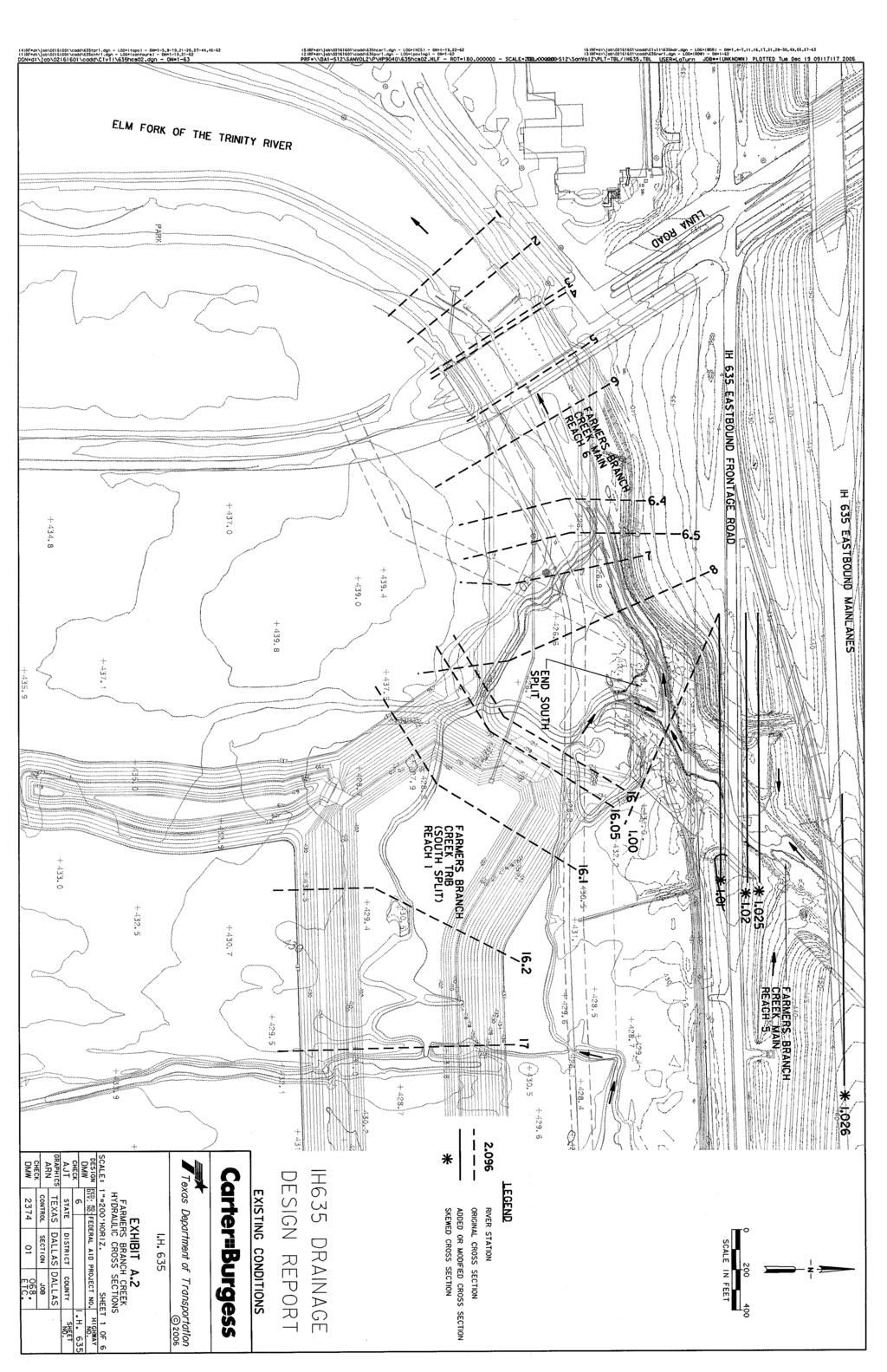
84
85
86
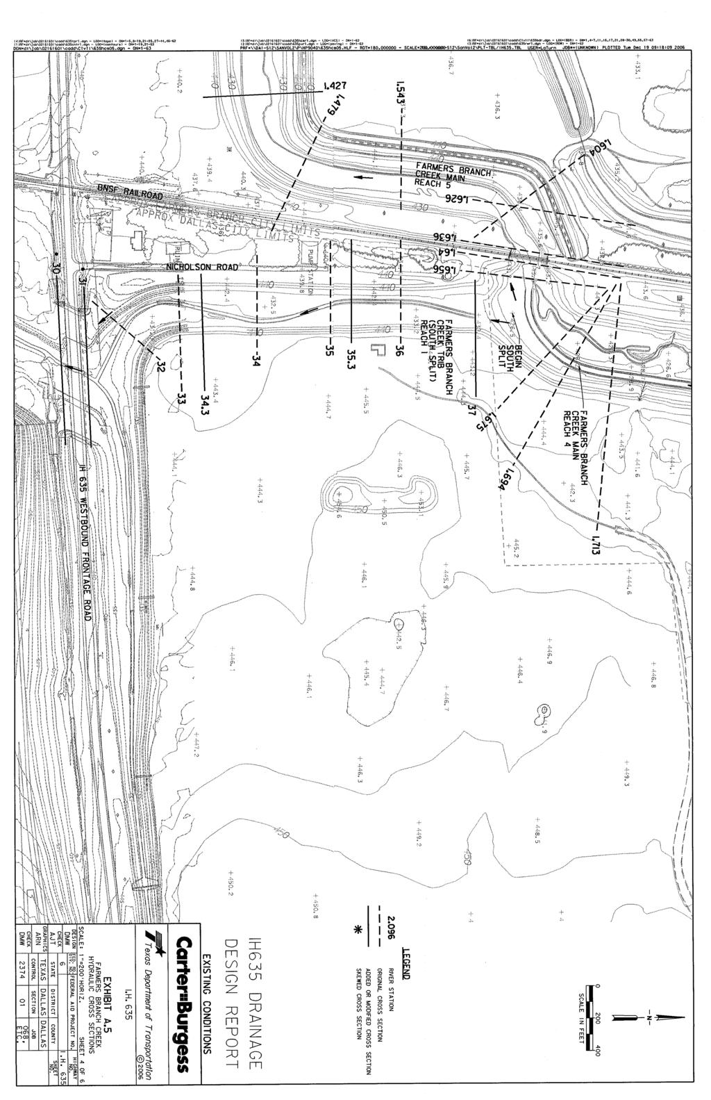
87

88
89

90
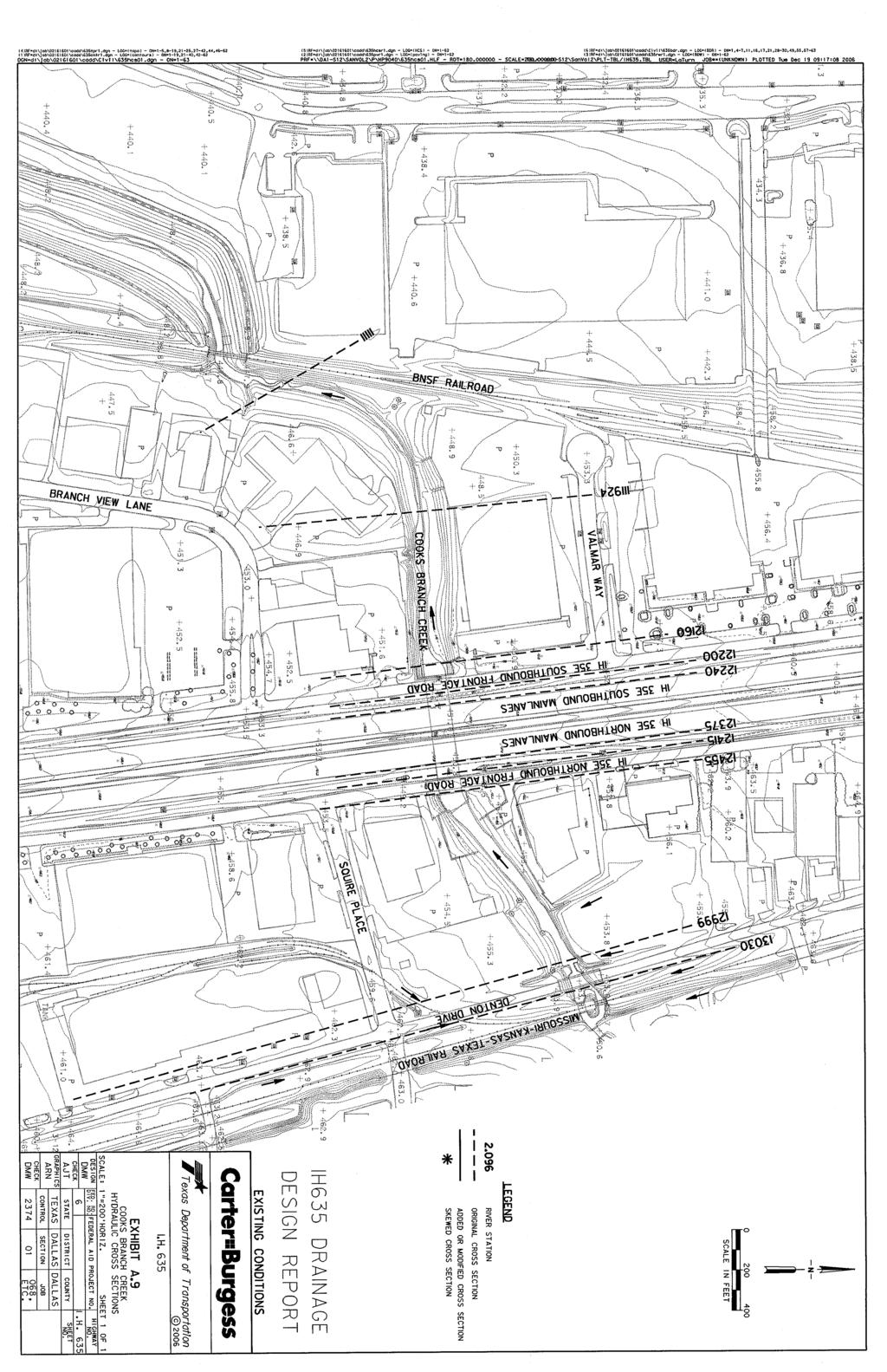
91
92
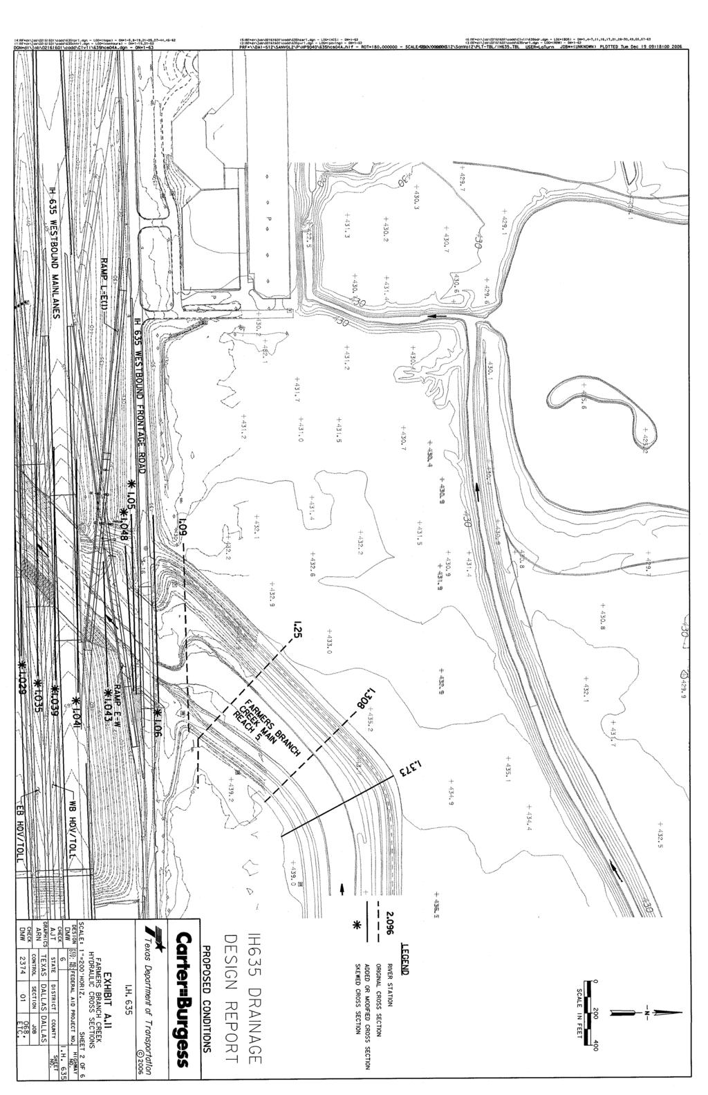
93
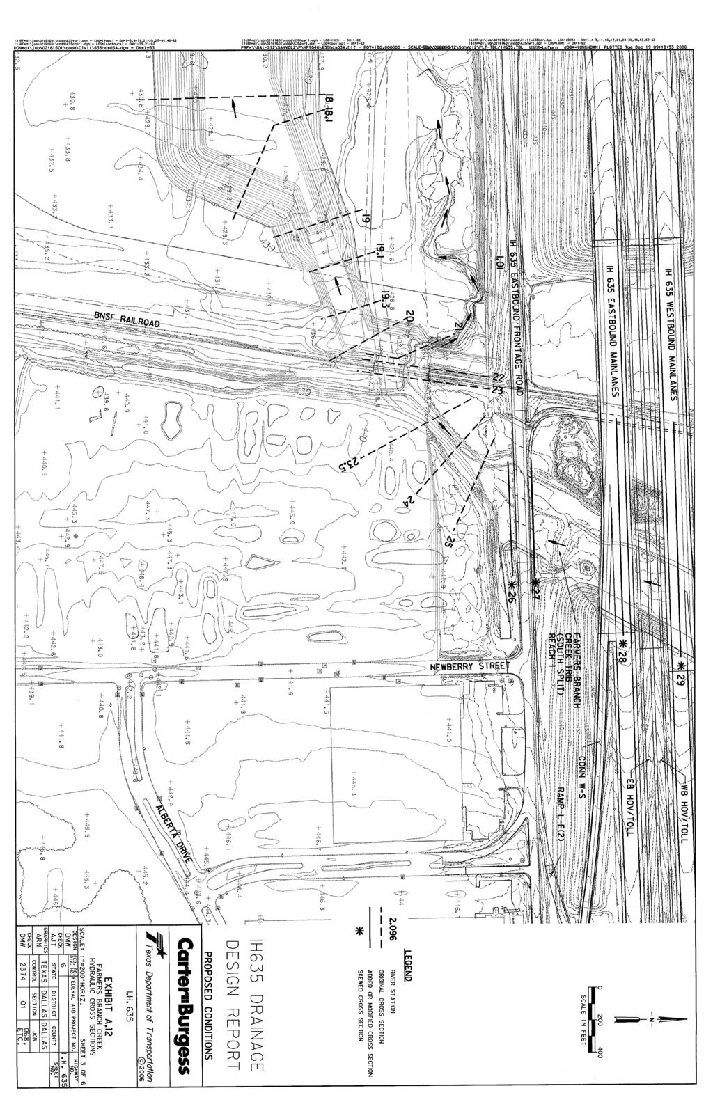
94
95
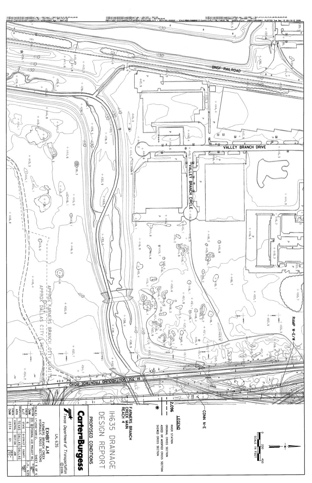
96
97
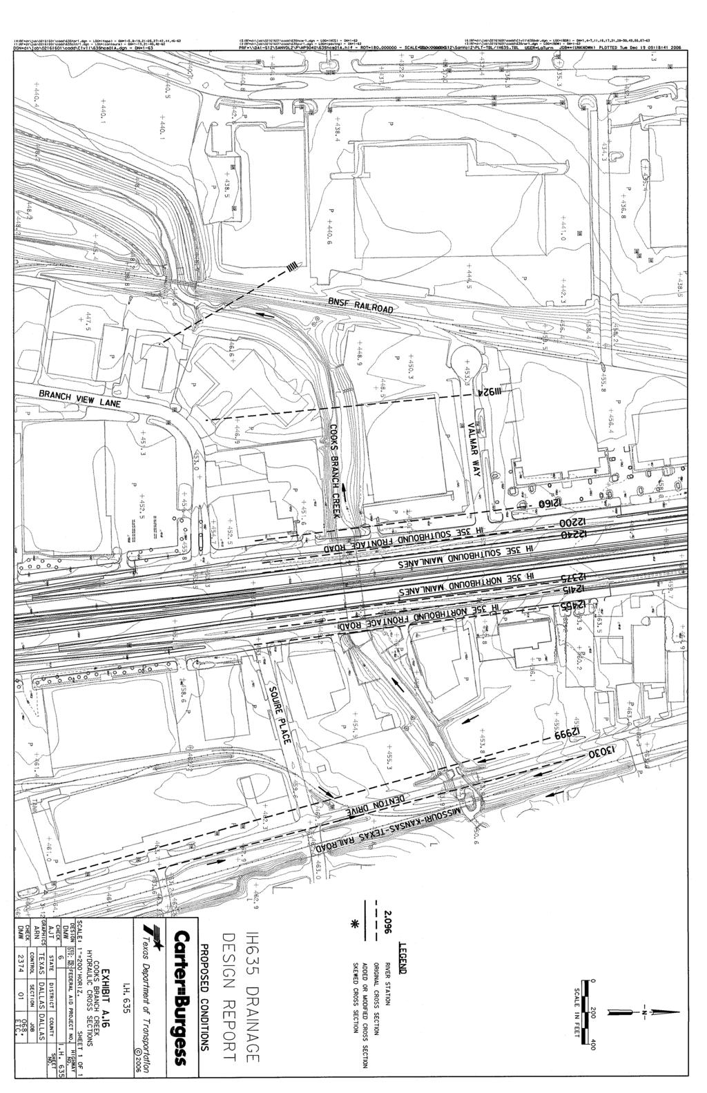
98