DRONE REPRESENTATION...
|
|
|
- Debra O’Neal’
- 5 years ago
- Views:
Transcription

1 REALISTIC DRONE A project by AnanasProject Content INTRODUCTION... 1 OBJECTIVES... 1 PROJECT STRUCTURE... 1 DRONE REPRESENTATION... 2 SENSORS... 2 LAYER 0: STABILIZATION... 3 FLYING PRINCIPLES... 3 PID CONTROLLER... 4 PID IMPLEMENTATION... 5 STABILIZATION FUNCTIONS... 5 STABILIZATION UML... 7 LAYER 1: TRAJECTORIES... 8 SINGLEPOINT... 8 Pros and Cons... 8 WAYPOINTCIRCUIT... 9 Pros and Cons... 1 WAYPOINTPROGRESSTRACKER... 1 TRAJECTORIES UML... 1 LAYER 2: ARTIFICIAL INTELLIGENCE... 2 AI UML... 2 AI EXAMPLE: MAZE EXPLORATION... 3 Maze Exploration UML... 5 EXAMPLES... 6 DOOM-LIKE DRONE... 6 SHOOT TO THE DRONE... 6 FOLLOWING CAM DRONE... 7 CONCLUSIONS... 7 IMPORTANT: CONFIGURATION... 7
2 INTRODUCTION Drones, especially in their most classical form: the quadcopters, are a phenomenon that is becoming really relevant in recent years. These devices, combined with algorithms that allow their autonomous operation, can solve an apparently infinite number of tasks; from exploration of territories and data collection, to rescue missions in environments where direct human presence is impossible or dangerous (like sites with a high amount of radiation or simply that are not possible to reach). Objectives This package has the objective to simulate a real drone in a real environment. Is for this reason that I choose the Unity Engine: it already simulates physics in a realistic way; thanks to the virtual environment is possible to simulate outputs of the sensors we can find in a real drone; offers the possibility to use high-levels functions (like raycast, to measure the distances). The resulting package could have different destinations: - Inside Unity3d it can be used in multiple ways: the drone could be a player (enemy or guided by human) that flies over the environment and respond in a realistic way to events such as forces (like wind or pushes) - All the code can be exported to a real drone: In fact, the code has been written to simulate as realistically as possible the functioning of a drone, miming the algorithms used to fly it. For this reason, with some modifications, the functions can fly a real drone. Project Structure The project has been developed using a layered structure, where each layer uses the information passed by the next layer and virtualize all the subjacent layers. In this manual the layers will be explained exhaustively, using also UML schemes. The layers are: - Stabilization (Layer 0): implements all the functions necessaries to the stabilizations of the drone. It uses the outputs of the sensors to figure out the situation and actuate directly on the propellers to reach a stable state. - Trajectories (Layer 1): this layer is the responsible of the movements of the drone. It gives to the underlying layer the position it has to stabilize in and guide all the movement process. - Artificial Intelligence (Layer 2): in this layer is possible to implement the high-level behaviours of the drone. A socket (represented by an inheritable class) is used to command the Trajectories Layer, while the AI algorithms should be implemented in classes in this layer. This offers a great freedom in what the drone will do. 1

3 DRONE REPRESENTATION The model of drone is composed by the following fundamental parts: - A 3D model of drone - A collection of sensors The 3D model has been found on internet ( It was almost ready from the beginning; the only modification was about the helixes: I made them from scratch to permit the animation. Sensors The sensors used are the same we can find in every existing drone and they are necessary to permit the fly: - Accelerometer: returns lineal velocity and acceleration of the drone. - Gyroscope: gives the values of Pitch and Roll of the drone and the values of angular velocity and acceleration. - Barometer: used to determine the altitude of the drone, vertical velocity and acceleration. - Magnetometer: gives information about the actual rotation in the Yaw axis. Using this value it is possible to extract the rotation velocity. - GPS: returns the coordinates X and Z of the drone The sensors return precise results (because they take the information from the engine), to simulate real world sensors has been added a component that introduces noise on the measurement. Obviously this can be disabled, if necessary, to increase the stability. 2
4 LAYER 0: STABILIZATION Flying Principles A quadcopter fly thanks to its four propellers, each one produces an airflow that transform itself in terms of acceleration force applied on the body of the drone. The direction of rotation is also important: two motors rotate clockwise and two counterclockwise. This is necessary because each propeller produces a torque force in its rotation direction that need to be compensated by another propeller. If the four propellers are working at the same velocity, the drone remains stable Increasing or decreasing the velocity of the four propeller will cause changes in the altitude Increasing the velocity of a couple of them will produce a movement in the opposite direction Modifying the velocity of the clockwise or counterclockwise propeller will cause the rotation of the drone in that direction 3

 A Proportional-Integral-Derivative controller (PID controller) is a control loop feedback mechanism commonly used in industrial control systems.")
5 Thanks to these possible configurations of propellers, the drone can rotate its body along three axes: Pitch, Roll and Yaw. So to control the movement the only thing we have to do is to cause variations in the rotation along these axes and, as consequence, the drone will modify its orientation and position. Doing this could look simple but requires to use a trick: the PID controller. PID Controller In a nutshell, (as Wikipedia says) A Proportional-Integral-Derivative controller (PID controller) is a control loop feedback mechanism commonly used in industrial control systems. A PID controller continuously calculates an error value as the difference between a desired set-point and a measured process variable. The controller attempts to minimize the error over time by adjustment of a control variable, such as the position of a control valve, a damper, or the power supplied to a heating element, to a new value determined by a weighted sum: Where K p, K i, and K d, all non-negative, denote the coefficients for the proportional, integral, and derivative terms, respectively (sometimes denoted P, I and D). In this model, P accounts for present values of the error. For example, if the error is large and positive, the control output will also be large and positive. I accounts for past values of the error. For example, if the current output is not sufficiently strong, error will accumulate over time, and the controller will respond by applying a stronger action. D accounts for possible future values of the error, based on its current rate of change. 4
6 PID Implementation To obtain stability it is necessary to use the values returned by the sensors, compare them with ideal values and send the resulting error to the propellers to increase or decrease their rotation velocity and is for this kind of job that we need the PID Controllers. To implement it we use a class called PID. The constructor of this class accept the parameters P, I, D and U and won t be possible to modify this values during run-time. While I have already explained the use of the P, I and D terms, the U value is just multiplied to the final result of the PID: setting it at 0 will set to 0 every result, while setting it to 1 won t change the results. So the result of the PID will be obtained calling the function getu ( float Error, float deltatime ) It ll calculate the factors (Proportional, Integral, Derivative) and will multiply them to the corresponding constants, in the form: Stabilization Functions ( pfactor * P + dfactor * D + ifactor * I ) * U Due to the different types of movements that the drone can perform, we need multiple stabilization algorithms. The possible manoeuvres are: - Vertical movement (along Y axis) - Rotation along Y axis - Rotation along X axis (Roll, causes movement along the X axis) - Rotation along Z axis (Pitch, causes movement along the Z axis) Each manoeuvre needs a stabilization mechanism and each stabilization mechanism needs the outputs of the corresponding sensors. Now let s imagine we just want to increase the altitude of our drone by 10 meters; passing to the PID controller the pure error (desired_altitude - actual_altitude = 10) won t be enough to obtain a good response and stability: the result would be (more or less) as follows 5

7 In fact, we have to consider a wider range of variables, like vertical velocity and acceleration, to be sure that the PID will make us get near the zero error without oscillations. Using all the other variables obtained from the sensors, we obtain this behaviour: distance vel. acc. idealvel. idealacc The blue line represents the distance from our set-point (the error), while the other lines represent the velocity, the acceleration, the ideal velocity, the ideal acceleration. The resulting error is more precise and permits the drone to reach the set-point quickly and without oscillation: as the green line shows, the ideal acceleration gets negative when the error decrease too rapidly, that decrease the velocity and gets the drone to the desired altitude with 0 acceleration and 0 velocity and that means good stability. The same procedure is repeated for each of the others movements. Each one has an algorithm slightly different but they all use the same values and a PID. The result of the interaction of the different stabilization algorithms can be resumed with the following scheme: It could seem complicated right now, but in the project each piece of code is commented and well explained. 6

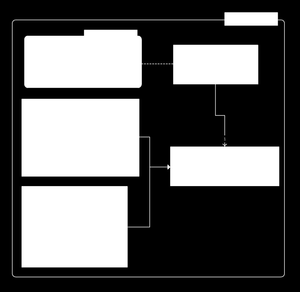
8 Stabilization UML The UML relative to this part is the following: 7
 we can move the drone without taking in consideration")
9 LAYER 1: TRAJECTORIES Now that we have a basic system to move the drone, we have to plan a way to create trajectories or move the drone to a set-point. This part represent another layer that is located above the last one: simply giving some instructions (represented by points and orientations) we can move the drone without taking in consideration the low-level part (represented by the velocity of the propellers, the PIDs management and the sensors output). To grant freedom in movements in different situation, there are two types of objects that allow the movements of the drone: - SinglePoint: used to move the drone from one point to another and can be used as interface to move the drone by an user. - WaypointCircuit: object developed by Unity to move AI vehicles as cars or planes. It has been remodelled to allow the movements of the drones in the air, using physics. It consists is a list of points and uses internal functions to modify the speed of the drone, this allow clean and precise movements along the circuit. SinglePoint The SinglePoint object is used to freely move the drone. It consists in two points in space: one represent the point the drone will have to go to, the second represent the orientation of the drone. Is important to say that, as the movement system is based on PIDs controllers, larger is the error (the distance between the drone and the point) higher will be the output returned by the PIDs to correct the error as soon as possible. This permits the user to modify the speed of the drone sending away or bringing nearer the SinglePoint object. Wanna try? Here there is the SinglePoint DEMO 8

10 Pros and Cons Usable as interface to drive the drone Simple to use Orientation and direction are independent, this allows to go in a certain direction while watching in another direction It is possible to modify the speed modifying the distance It takes in consideration just a point so the user has to brake or decrease the velocity of the drone manually if there will be a change in the direction Orientation and direction are independent, this could be bad for stability The speed of the drone is regulated just by the distance, this sometimes causes problems or doesn t grant a stable flight WaypointCircuit The second object used to drive the drone is the WaypointCircuit. This object is more trajectories-oriented and permits to set a list of points that the drone will follow. Moreover, it uses internal functions to modify the velocity of the drone in a similar way to the SinglePoint: modifying the distance of the target along the circuit. A fundamental difference with the SinglePoint is that in this object the target and the position of the drone aren t the same point: - The TARGET is a point that is always in front of the drone, it is the point the quadcopter has to reach and it will be used also as orientation point (i.e. the point the drone will look at). To get to the target we will just modify the Pitch of the drone, which represents the movement forward/backward. - The POSITION is the point the drone has to stay into all the time and it is used to avoid the drone exits from the circuit. Related to the position is the Roll of the drone, which represents the movement right/left. 9
11 Wanna try? Here there is the Circuit DEMO Pros and Cons Simple to configure, just have to add the points to the object s list and it ll automatically create a smooth circuit Orientation and direction are bounded and this has a positive impact over the general stability It considers the Target point and the following ones. In this way it can bring the target nearer to the drone to reduce its velocity (if it has to turn) or move it farther if it encounters itself in a straightway. It is possible to modify the points of the circuit during runtime Perfect to move the drone using an AI Orientation and direction are bounded, so the drone has to look always forward Is a fixed way to move the drone, more adapt to AI than human users WaypointProgressTracker The last object of this layer we are considering in this manual is the WaypointProgressTracker, that has three fundamental tasks: - Toward the lower layer -> changes the positions of Target and Position so the drone can follow its path. - Toward the same layer -> cooperates with the WaypointCircuit to modify the distance of the Target and the velocity of the drone while it is following its path. - Toward the upper layer -> used by the AI script to modify the considered object (WaypointCircuit or SinglePoint) This object also permits to switch during runtime between different WaypointCircuits or between a WaypointCircuit and a SinglePoint. 1
12 Trajectories UML 1

13 LAYER 2: ARTIFICIAL INTELLIGENCE The last part of the project is about the AI of the drone. This component could be fundamental in some applications, while could be avoided in some others. For this reason, this part is pretty raw: as it is impossible to create something that adapts to every possible situation, I just create a plug class that can be inherited to control the subjacent layer in a simple way, but the AI part has to be written by the user of the application. AI UML 2

14 AI example: Maze Exploration In this section I will show an AI application for the drone: the exploration and mapping of an unknown environment by a drone or a group of drones. In summary, until now, we have a drone that can move and some objects that are useful to move the drone. However, where has it to go? This is the reason for the AI part: to decide what to do, using external input or internal sensors. To explore an environment we need additional sensors that can detect obstacles or walls. These sensors in real life would be a sonar (cheap but unprecise) or a laser (expensive but very precise). Luckily, in a virtual environment we do not have to worry about this kind of costs and we can be creative and find a good way to solve our problem. Another positive thing is that Unity has Raycasts, which are perfect to approximate a laser beans that can give us information about the surrounding environment. So we implemented them in the drone. Here in the image we can see a drone in the middle that is flashing a big amount of Raycasts, using the collision points of these rays we know where the walls are. The next step is to create an object that will store all the information about the obstacles. The easiest way to do that is to put everything is a squared matrix, where each coordinate can be translated to a point in space and vice versa. The matrix could be also cubic, in this way we are able to represent effectively a 3D space, it depends what we want to do, the rays directions and how much space do we have to store everything. Anyway, as you will see, often a 2D matrix is enough to explore a flat environment. 3

15 Once we have that object we can continually send information about the points crossed by the beam, in fact there could be a wall or nothing. Our matrix is made by bytes, in this way we can store - 0 -> if the point is empty - 1 -> if the point is a wall - 2 -> if the point is unknown Once this part is done, we have to create a graph in the environment that will be used by the drone to navigate from one point to another. We can also use the graph to determine the zones of the map we still have to explore. This is done using the matrix-object as reference. 4

16 Maze Exploration UML The resulting UML is represented in the following image: 5


17 EXAMPLES Doom-like Drone It is possible to build a simple Doom-Like game using the drone as player. We just have to mount a pistol under our drone and add some shooting effects. The final result is a drone capable of moving in the environment, creating a map during runtime and shooting to everything that moves! Video at Shoot to the Drone Thanks to the physics is easy to shoot to a drone and make it fall to the ground. We just have to push it! Video at 6

18 Following Cam Drone Putting a camera on a drone and make it follow you looks like a great idea in the recent times. Video at CONCLUSIONS As shown in these pages, the Realistic Drone package can be a great resource if we want to simulate actual drones in our games. The approach used in the construction of it (i.e. as-it-was-real) allows us to obtain realistic behaviours that include falls to the ground, instability, limited velocity, rotating movements, etc. that are difficult to mimic using a drone that moves in other ways. Moreover, thanks to the trajectory objects the drone is easy to drive and offers a realistic experience. IMPORTANT: CONFIGURATION In order to use this package, you have to - Set the variable Fixed_Timestamp to 0.05 (you can find it in "Edit / Project Settings / Time") - Restart Unity (maybe it is necessary to restart 2 times!) Without these passages the drone will not fly in a stable way. It is possible to check if everything is working correctly just having a look at the first scene: If the drone flies and remains stable in the air, it means that everything is OK! 7