Robust Design at GKN Aerospace
|
|
|
- Alexia Pierce
- 5 years ago
- Views:
Transcription
1 Robust Design at GKN Aerospace Robust Design Day 2015 at DTU Sören Knuts, The information contained in this document is GKN Aerospace Sweden AB Proprietary information and it shall not either in its original or in any modified form, in whole or in part be reproduced, disclosed to a third party, or used for any purpose other than that for which it is supplied, without the written consent of GKN Aerospace Sweden AB. The information contained in this document may also be controlled by export control laws. Unauthorized export or re-export is prohibited. Any infringement of these conditions will be liable to legal action.
2 Agenda -Present the presenter -Present GKN Aerospace -Robust design issue -Identification of sources of variation -Creating a Robust Business through unrobustness -Six Sigma to resolve robustness problems -GKN Robust Design includes KC Identification -GKN Robust Design includes Geometry Assurance Process 2 Document title
 at")


 since 2009.")


3 Sören Knuts, PhD, 6sBB M Sc in Engineering Physics, PhD in Quantum Chemistry (Computational Chemistry) at the University of Uppsala I began at Volvo Aero in Trollhättan, 1995, in Space Propulsion Division at Nozzle department, with design, testing and validation of Ariane 5 nozzles Vulcain and Vulcain 2. Between 2001 and 2006 I have worked as a reliability engineer at Saab Automobile with risk analysis, FMEA, statistical analysis and Design for Six Sigma. Specialist in Design for Robustness of GKN Aerospace Sweden (Previous Volvo Aero Corporation) since Focus areas Risk Management, Probabilistic Design and Six Sigma. Is regularly running Master Thesis works and student projects related to robust design and six sigma Has many years participated in European Network of Business and Industrial Statistics (ENBIS) with presentations 3


4 GKN: Engineering that moves the world Every day, we drive the wheels of hundreds of millions of the world s cars, we help thousands of aircraft fly safely, we deliver the power to move earth and harvest crops, and we make the essential components for industries that touch lives across the globe. Our four divisions are all market leaders, each outperforming their markets, with a leading market share in their segment. This breadth gives us unrivalled expertise and experience in cutting-edge technology and engineering. GKN Driveline GKN Powder Metallurgy GKN Aerospace GKN Land Systems


5 GKN Aerospace Making Things Fly Components for aircraft engines and gas turbines Military aircraft engines Sub systems for rocket engines Engine Services Sales by product type Sales by market 2,226 m sales in ,000 employees Aerostructures Engine components and sub-systems Special products Civil Military

6 Engine Product Portfolio

7 Engine Systems has a strong presence in today s aircraft fleets More than 90 percent of all new large commercial aircraft engines use our components For these aircraft we provide: Engine components Engine technology Engine technical support Engine MRO services Parts Repair

8 Hot topics in GKN Research &Technology 3D metal printing Automized welding Lighter structures
9 Robust Design issue Main issue: Can we design our products and processes so they are insensitive to sources of variation? 9


10 Identification of sources of variation In manufacturing and service phases Classical Bathtub curve 10
11 Identification of sources of variation P-diagram Ishikawa diagram VMEA FMEA GKN Design Problem System Factors, XS Control factors, Xc System Key Product design and process parameters" Respons, Y Noise Factors, XN Voice of the process To identify control and noise factors/parameters To identify quality parameters or characteristics related to hardware and process 11 Document title


12 Creating a Robust Business through unrobustness Make it light From heavy casting structures Light fabrication structures 12
 Assembly line with Process Controlled Product manufacturing Challenge for fabrication: Reach tolerance level of one big casting: 0.")
13 Creating a Robust Business through unrobustness Make it light From heavy casting structures Light fabrication structures One-piece manufacturing (skilled craftsman) Assembly line with Process Controlled Product manufacturing Challenge for fabrication: Reach tolerance level of one big casting: 0.1 mm in machining operation 13

14 Experienced unrobustness in fabrication Geometry deviations/deformations/mismatch Dimensions Cracks/ Weld defects Material defects Welding process parameters Experienced by External/internal customer High leadtime High number of Non-conformances Expensive rework 14 Document title

15 Manufacturing process in statistical control No identification Identification Process in control According to six sigma methodology is a process is stable, predictable, and in-control when only common cause variation exists in the process. Common-cause variation is the noise within the system. The unpredictable variation in a process caused by a unique disturbance or a series of them. Special cause variation is typically larger than common cause variation

16 Six Sigma to resolve robustness problems Workflow, DMAIC process and toolbox DMAIC stands for Define, Measure, Analyze, Improve and Control, and is one of the most common resolution processes within six sigma. Good questions in the different phases. 16 Document title
17 Measureability by using Key Characteristics Definition in academic literature: a quantifiable feature of a product or its assemblies, parts or processes whose expected variation from target has an unacceptable impact on the cost, performance, or safety of the product (Ref. Thornton, A.C.(2004), Variation Risk Management, Hoboken, NJ: John Wiley and Sons) Not a KC Low variation and low cost for deviations Definite KC High variation and high cost for deviations Process output Variation costs LSL Target value USL LSL Target value USL
18 Definition of Key Characteristic Definition of Key Characteristic according AS9100C (Aerospace standard) 3.4 Key Characteristic (KC) An attribute or feature whose variation has a significant effect on product fit, form, function, performance, service life or producibility, that requires specific actions for the purpose of controlling variation. That implies for GKN following classification standard: Critical Characteristic => Safety if nonconforming, missing or degraded may cause a Failure mode that could lead to injury or system loss. Major Characteristic => Safety & Reliability if nonconforming, missing or degraded may cause a Failure mode that could lead to mission failure Significant Characteristic => Reliability & Robustness deviation from nominal value has a significant effect on product fit, form, function, performance, service life or producibility and therefore requires specific actions for the purpose of controlling variation. KEY Robustness Characteristic => Robustness (Internal use) deviation from nominal value has a significant effect producibility and therefore requires specific actions for the purpose of controlling variation. RC 18

19 GKN Robust Design includes KC Identification Toolbox for investigating Robust Design features Also adressed within Aerospace industry standard 19 Document title
20 Final Design Detailed Design Preliminary Design KC Identification and Classification Maintenance DFMECA Identify potential areas for KC Investigation Design Engg Manufacturing Analysis Hardware DFMECA Identification of important design parameters based on design studies FMECA Document FMECA Template Reports Maintenance FMECA Document DFMECA Creation of potential characterist ics Design Engg Manufacturing Analysis Hardware DFMECA Assessment & mitigation of potential characteristics based on studies FMECA Document Reports Maintenance FMECA Document Design Engg Manufacturing Analysis Hardware DFMECA Classification of characteristics based on studies FMECA Document Reports 20 Document title
21 KC Identification The number of Key Characteristics over the phases of a project should reduce, as per the following schematic Preliminary Design Large Pool of Potential KCs Identification of the guiding parameters which are important for the design Open View towards KCs Detailed Design KC Elimination Based on Analysis Multi-functional analysis eliminates need for KCs based on proving of variation sensitivity Collection of Evidence Final Design KC Finalisation Conclusion about sensitivity 21 Document title
22 (Vane) (Shroud) (Hub) KC Identification using Flowdown diagram Example: Identification of Potential KC in a TEC-Sector Customer requirement Customer Requirement of welding for sector Product KCs (Sector) Good visual condition Defects fullfillment According to Requirement Offset between Parts (Hub Vane Shroud) Repeatable appearance Sector is welded System KCs (Shroud Vane Hub) Positioning of vane Between shroud and Hub requirement before weldning Gap/offset Assembly KCs Shroud/Hub Aperture Part KCs Profile of surface on Vane Vane Locating Features Profile of surface on Shroud Shroud Locating Feature Profile of surface on Hub Hub Locating Feature Process KCs Manufacturing of Vane Vane Fixtures Manufacturing of shroud Shroud Fixtures Manufacturing of Hub Hub Fixtures
23 KC Identification using Flowdown diagram Customer Requirement for welding of sector: Good visual condition Geometry requirement fulfilment of Offset between Part (Hub Vane Shroud) Defect, requirement fulfilment Repeatable appearance Mechanical strength and life Aero performance etc.
24 (Vane) (Shroud) (Hub) KC Identification using Flowdown diagram Example: Identification of Potential KC in a TEC-Sector Customer requirement Requirement of welding for sector Customer Product KCs (Sector) Good visual condition Defects fullfillment According to Requirement Offset between Parts (Hub Vane Shroud) Repeatable appearance Sector is welded System KCs (Shroud Vane Hub) Positioning of vane Between shroud and Hub requirement before weldning Gap/offset Assembly KCs Shroud/Hub Aperture Part KCs Profile of surface on Vane Vane Locating Features Profile of surface on Shroud Shroud Locating Feature Profile of surface on Hub Hub Locating Feature Process KCs Manufacturing of Vane Vane Fixtures Manufacturing of shroud Shroud Fixtures Manufacturing of Hub Hub Fixtures
25 KC Identification using Flowdown diagram Offset between Parts, (Hub Vane Shroud) after the Sector is welded Potential KC: Offset requirement


26 KC Identification using Flowdown diagram Potential KC for parts: Profile of surface 1 A B C Weld interface A1 C A2 Note: Requirement is verified with Target System: A B C B A3
 Lesson Learned Six Sigma / Root Cause Analysis Variation Simulation /")
 Offline")
27 GKN Robust Design includes Geometry Assurance Process RD&T is our tool Robust Design (Target systems) Lesson Learned Six Sigma / Root Cause Analysis Variation Simulation / Stack-up s RSS & WC PRODUCTION Inspection Database 3D 1D /2D CONCEPT KC SPC Tolerance Allocation VERIFICATION Virtual Verification (Inspection Preparation) Offline programming
 Offline")
28 GKN Robust Design includes Geometry Assurance Process RD&T is our tool Robust Design (Target systems) Lesson Learned Six Sigma / Root Cause Analysis Variation Simulation / Stack-up s RSS & WC PRODUCTION Inspection Database 3D 1D /2D CONCEPT KC SPC Tolerance Allocation VERIFICATION Virtual Verification (Inspection Preparation) Offline programming

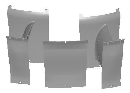
29 Using Production data in reengineering Reengineering project Old New

30 Using Production data in reengineering Analysis- Machining stock based on Old Data Background Problem Old weld offset is controlled with forces in fixture NEW weld offset is controlled with machined interfaces Define machining stock based on Old Data KC: Requirement on Weld offset Machining Stock

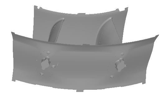
31 Analysis- Machining stock based on Old Data In the project the old sector is measured by GOM after welding. In this case the A targets on the shroud casting is really interesting. The distortion in the A points on the shroud is measured with the target system of the hub as a zero. The analysis is based on 25 measured parts Datum targets (A) on the shroud casting


32 Analysis- Machining stock based on Old Data In this case the variation simulation software RD&T is used together with the measurement data to capture 3D effects. Since 25 measurements were available 25 different possible positions of the shroud is captured. To be able to capture the right position of the part the distortion from the measurements is defined in the targets of the shroud casting illustrated by the red arrows. Using the function color coding of variation a virtual measurement point is placed in order to capture the levering effect based on the distortion in the A targets.
 can be used.")
 ± 2,32 Machining stock.")
33 Analysis- Machining stock based on Old Data Results A histogram is presented based on the 25 runs. The outcome is normally distributed meaning that the traditional ±4σ (standard deviation) can be used. Using a casting tolerance profile of surface of 1,5 and a thickness of ±0,3mm and a safety factor of 0,25 the recommendation is to have a stock of ± (1,02 + 0,75 + 0,3 + 0,25) ± 2,32 Machining stock. Result and input data is normally distributed


34 To Summarize GKN Robust Design process- Making things insensitive to variation: Identification of sources of variation and criticality level Assessment of variation risk and prioritization Mitigation and choice of mitigation strategy Adressing the need for Measurement System (MSA) and SPC. Efficient recovery having data to do Root Cause Analysis and Six Sigma work Key Characteristics Geometry Assurance 34 Document title
35 Thank you for listening! Q&A!