Functional Servicing Report
|
|
|
- Samson Stevenson
- 5 years ago
- Views:
Transcription
1 Functional Servicing Report 4063 UPPER MIDDLE ROAD CITY OF BURLINGTON January 2017 SLA File: South Service Road, Suite 105, East Wing Burlington, Ontario L7N 3H8 Tel. (905) Fax (905)
2 TABLE OF CONTENTS Page 1.0 INTRODUCTION AND BACKGROUND OVERVIEW BACKGROUND INFORMATION STORMWATER MANAGEMENT EXISTING CONDITIONS PROPOSED CONDITIONS SEDIMENT AND EROSION CONTROL SANITARY SEWER SERVICING EXISTING CONDITIONS SANITARY DEMAND PROPOSED SANITARY SERVICING AND CAPACITY ANALYSIS DOMESTIC AND FIRE WATER SUPPLY SERVICING EXISTING CONDITIONS DOMESTIC WATER DEMAND FIRE FLOW DEMAND PROPOSED WATER SERVICING AND ANALYSIS CONCLUSIONS AND RECOMMENDATIONS... 8 TABLES 2.1 Pre-Development Condition Catchment Areas Pre-Development Condition Discharge (Catchment 101 & 102) Post-Development Condition Catchment Area Post-Development Condition Stage-Storage Discharge (Catchment 201) Post-Development Condition Site Discharge Post-Development Sanitary Sewer Discharge Post-Development Domestic Water Demand... 7 FIGURES 1.0 Location Plan... 2 APPENDICES Appendix A Stormwater Management Information...Encl. Appendix B SWMHYMO Input/Output Information...Encl. Appendix C Hydroguard Information...Encl. Appendix D Water Analysis Information...Encl. Appendix E Preliminary Engineering Plans...Encl.
3 Upper Middle Road, Burlington January INTRODUCTION AND BACKGROUND 1.1 OVERVIEW S. Llewellyn & Associates Limited has been retained by thinkgiraffe Environmental Design to provide Consulting Engineering services for the proposed development at 4063 Upper Middle Road in the City of Burlington (see Figure 1.0 for location plan). This report will outline the functional servicing and stormwater management strategy for the proposed development. The proposed development consists of constructing a 7-storey residential apartment building. The 7-storey building will contain a total of 32 residential units and a 3-level parking structure. This Functional Servicing Report will provide detailed information of the proposed servicing scheme for this development. Please refer to the preliminary site engineering plans prepared by S. Llewellyn and Associates Limited and the preliminary site plan prepared by thinkgiraffe Environmental Design for additional information. 1.2 BACKGROUND INFORMATION The following documents were referenced in the preparation of this report: Ref. 1: MOE Stormwater Management Practices Planning and Design Manual (Ministry of Environment, March 2003) Ref. 2: City of Burlington Standard Drawings (City of Burlington, March 2004) Ref. 3: Halton Region Water and Wastewater Linear Design Manual (Halton Region, May 2014) Ref. 4: Erosion & Sediment Control Guidelines for Urban Construction (December 2006) S. Llewellyn & Associates Limited Page 1 of 9
 criteria will be applied to the site, in accordance with the City of Burlington: Quantity Control The stormwater discharge rate for")
4 Upper Middle Road, Burlington January 2017 Figure 1.0 Location Plan 2.0 STORMWATER MANAGEMENT The following stormwater management (SWM) criteria will be applied to the site, in accordance with the City of Burlington: Quantity Control The stormwater discharge rate for the proposed site shall be controlled to the 5-year predevelopment condition discharge rate for all storm events up to and including the 100- year event. Quality Control The stormwater runoff from the prosed condition site must meet Level 1 (Enhanced) stormwater quality control (80% TSS removal, 90% average annual runoff treatment). Erosion Control Erosion and sediment control measures will be implemented in accordance with the standards of the City of Burlington. S. Llewellyn & Associates Limited Page 2 of 9
5 Upper Middle Road, Burlington January EXISTING CONDITIONS In the existing conditions, the subject land is currently a residential lot with gravel, grassed areas and an existing 1-story dwelling. The site is bound by Upper Middle Road to the south, and existing residential units to the north, east and west. Approximately half of the existing site drains to the 900mmᴓ storm sewer along Upper Middle Road and the remaining half drains to Shoreacres Creek at the northeast portion of the property. Two catchment areas, Catchment 101 and 102 have been identified in the existing condition. Catchment 101 represents the existing conditions discharging to Upper Middle Road, Catchment 102 represents the existing conditions discharging to Shoreacres Creek. See Table 2.1 below and the Pre-Development Storm Drainage Area Plan in Appendix A for details. Catchment ID Table 2.1- Pre-Development Catchment Areas Description Area (ha) % Imp. Runoff Coefficient 101 To Upper Middle Road To Shoreacres Creek An analysis was performed on Catchment 101 using the SWMHYMO hydrologic modelling program developed by J.F. Sabourin & Associates for the 2-year to 100-year City of Burlington Design Storms. A summary of the results can be found in Table 2.2 below and the detailed SWMHYMO input/output information in Appendix B. Catchment 102 is not included in this analysis as it will remain unchanged from its existing condition. Table Pre-Development Condition Site Discharge (Catchment 101) Storm Event Catchment 101 Discharge (m 3 /s) 2-Yr Event Yr Event Yr Event Yr Event Yr Event Yr Event PROPOSED CONDITIONS It is proposed to develop the site by constructing a 7-storey residential apartment building which will contain a total of 32 residential units and underground parking. It is proposed to service the site with a private storm sewer system, designed and constructed in accordance with the City of Burlington Standards. Three catchment areas, Catchment 201, 202 and 203 have been identified in the proposed condition. Catchment 201 represents drainage that is captured from the roof of the proposed building, the asphalt parking and landscape area around the building which S. Llewellyn & Associates Limited Page 3 of 9
6 Upper Middle Road, Burlington January 2017 will outlet via the proposed 250mmᴓ storm sewer and discharge to the existing 900mmᴓ storm sewer along Upper Middle Road. Catchment 202 represents the existing conditions discharging to the creek that will remain unchanged. Catchment 203 represents the uncontrolled drainage at the frontage on the property that will drain to Upper Middle Road. See Table 2.3 below and the Post-Development Storm Drainage Area Plan in Appendix A for details. Catchment ID Table 2.3- Post-Development Catchment Area Description Area (ha) % Imp. Runoff Coefficient Controlled to Upper Middle Road Uncontrolled to Upper Middle Road Water Quantity Control It is required to provide quantity control measures for the runoff from Catchment 201 by means of a 100mmᴓ orifice pipe to restrict discharge from the area to 0.019m 3 /s between storm MH1 and MH2. It is proposed to over control this area to include the runoff from Catchment 203. See Preliminary Site Servicing Plan for orifice pipe location. With the installation of the quantity control measures, Catchment 201 will be required to provide stormwater storage during storm events. To provide the required storage for Catchment 201, it is proposed to install a StormTech MC-4500 tanks under the proposed asphalt parking area. It is determined that the tanks will provide a total of 70m 3 of storage volume which will accommodate the stormwater storage required during the 100-year event. Details of the proposed storage tanks can be found in the Preliminary Site Servicing Plan. The stage-storage-discharge characteristics can be seen in Table 2.4 and Appendix A. Table Post-Development Condition Stage-Storage-Discharge (Catchment 201) Elevation (m) Underground Storage (m 3 ) Discharge (m 3 /s) (Orifice Invert) (Bottom of Tank) (0.5m Depth) (1.0m Depth) (Top of Tank) An analysis was performed on Catchment 201 & 203 using the SWMHYMO hydrologic modelling program developed by J.F. Sabourin & Associates for the 2-year to 100-year City of Burlington Design Storms. A summary of the results can be found in Table 2.5 below and the detailed SWMHYMO input/output information in Appendix B. Catchment 202 is not included in this analysis as it will remain unchanged from its existing condition. S. Llewellyn & Associates Limited Page 4 of 9
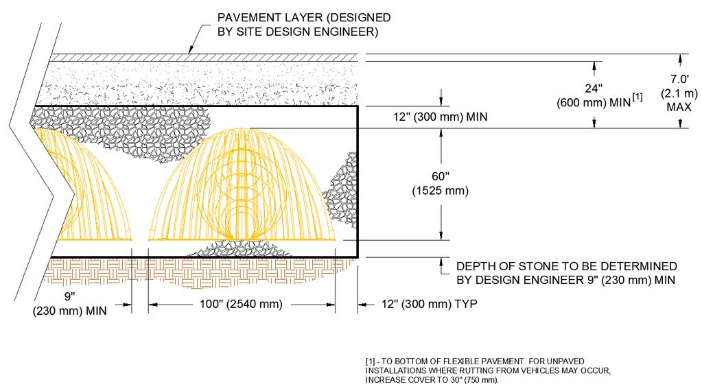
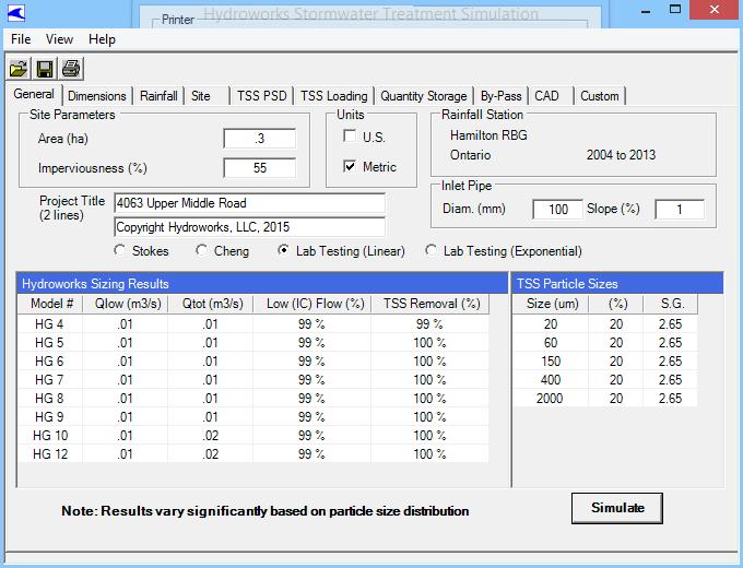
7 Upper Middle Road, Burlington January 2017 Storm Event Table Post-Development Condition Site Discharge Catchment 201 Discharge (m 3 /s) Catchment 203 Discharge (m 3 /s) Total Discharge (m 3 /s) Allowable Discharge Rate (Catchment 101) (m 3 /s) Required Storage (m 3 ) 2-Yr Event Yr Event Yr Event Yr Event Yr Event Yr Event This analysis determined the following: The proposed condition discharge rates will not exceed the existing 5-year discharge rate of 0.019m 3 /s during the 2-year to 100-year design storms, with the installation of a 100mmø orifice pipe between storm MH1 and MH m 3 of stormwater storage is required during the 100-year event, which can be accommodated by the proposed StormTech MC-4500 tanks. Water Quality Control The proposed development is required to achieve an Enhanced (80% TSS removal) level of water quality protection. To achieve this criteria, discharge from Catchment 201 will be subject to treatment from a Hydroguard oil/grit separator before ultimately discharging to the existing 900mmø storm sewer along Upper Middle Road. The Hydroguard sizing software was used to determine the required size of oil/grit separator unit for the site. It was determined that a Hydroguard HG4 will provide 99% TSS removal and 99% average annual runoff treatment, which satisfies the requirements for an Enhanced level for quality control. See Hydroguard unit sizing procedures in Appendix C for details. Hydroguard units require regular inspection and maintenance as per the manufacturer s specifications to ensure the unit operates properly. See Hydroguard Maintenance Manual in Appendix C for details. 2.3 SEDIMENT AND EROSION CONTROL In order to minimize erosion during the grading and site servicing period of construction, the following measures will be implemented: Install silt fencing along the outer boundary of the site to ensure that sediment does not migrate to the adjacent properties; Install sediment control (silt sacks) in the proposed catchbasins as well as the nearby existing catchbasins to ensure that no untreated runoff enters the existing conveyance system S. Llewellyn & Associates Limited Page 5 of 9
8 Upper Middle Road, Burlington January 2017 Stabilize all disturbed or landscaped areas with hydro seeding/sodding to minimize the opportunity for erosion. To ensure and document the effectiveness of the erosion and sediment control structures, an appropriate inspection and maintenance program is necessary. The program will include the following activities: Inspection of the erosion and sediment controls (e.g. silt fences, sediment traps, outlets, vegetation, etc.) with follow up reports to the governing municipality; and The developer and/or his contractor shall be responsible for any costs incurred during the remediation of problem areas. Details of the proposed erosion & sediment control measures will be provided on the Erosion and Sediment Control Plans, which will be provided upon final design. 3.0 SANITARY SEWER SERVICING 3.1 EXISTING CONDITIONS The site is located on Upper Middle Road, north of Walkers Line with an existing 200mmø sanitary sewer located along the frontage of Upper Middle Road. 3.2 SANITARY DEMAND Sanitary discharge from the site was estimated in accordance with the Halton Region Water and Wastewater Linear Design Manual (Ref. 3). Table 3.1 summarizes the sanitary sewer discharge rate from the subject lands. Table 3.1 Proposed Sanitary Sewer Discharge Site Area Population A (Apartment) 0.31 ha 32 units x 2 bedroom units = 64 persons Average Dry Weather Flow B 275 l/cap/day x 64 persons = l/s Harmon Peaking Factor C 4.29 Infiltration Allowance D Design Flow l/s/ha x 0.31 ha = l/s (0.204 x 4.29) = l/s A Type of Development to be Apartment B Average demand = 275l/cap/day x population C Peaking Factor = (1 + (14/(4 + Pe 0.5 ))) with Pe being the equivalent tributary population in thousands D Infiltration based on l/s/ha infiltration rate S. Llewellyn & Associates Limited Page 6 of 9
9 Upper Middle Road, Burlington January PROPOSED SANITARY SERVICING AND CAPACITY ANALYSIS The proposed apartment building will be serviced by a private 150mmᴓ sanitary sewer system, designed and constructed in accordance with the Halton Region standards. Drainage from this sewer will discharge to the existing 200mmᴓ sanitary sewer along Upper Middle Road. The minimum grade of the proposed 150mmᴓ sanitary will be 1.0%. At this minimum grade, the proposed sanitary sewer will have a capacity of m 3 /s (15 l/s). Therefore, the proposed 150mmᴓ sanitary sewer at 1.0% grade is adequately sized to service the proposed development. 4.0 DOMESTIC AND FIRE WATER SUPPLY SERVICING 4.1 EXISTING CONDITIONS The existing municipal water distribution system consists of a 400mmᴓ and 600mmᴓ distribution watermain located along Upper Middle Road. The nearest existing municipal fire hydrant is located at 4045 Upper Middle Road approximately 33m west of the proposed development. 4.2 DOMESTIC WATER DEMAND Water demand for the site was estimated in accordance with the Halton Region Water and Wastewater Linear Design Manual (Ref.3). Table 4.1 summarizes the domestic water demand requirements for the Average Daily, Maximum Daily and Peaking Hourly demand scenarios. Table 4.1 Proposed Development Domestic Water Demand Total Population A Average Daily Demand B 64 persons l/s Max. Daily Peaking Factor C 2.25 Max. Hourly Peaking Factor C 4.00 Max. Daily Demand Max. Hourly Demand (0.204 L/s x 2.25) = L/s (0.204 L/s x 4.00) = L/s A (32 units x 2 bedroom units) = 64 persons B Average Daily Demand = 275 l/cap/day x population C Max. Daily Peaking Factor = 2.25 (refer to sentence 2.4.1) D Max. Hourly Peaking Factor = 4.00 (refer to Table 2-2) E Max. Daily Demand = Average Daily Demand x Max. Daily Peaking Factor F Max. Hourly Demand = Average Daily Demand x Max. Hourly Peaking Factor 4.3 FIRE FLOW DEMAND Fire flow demands for development are governed by a number of guidelines and criteria, such as the Water Supply for Public Fire Protection (Fire Underwriters Survey, 1999), Ontario Building Code (OBC), and various codes and standards published by the National Fire Protection Association (NFPA). S. Llewellyn & Associates Limited Page 7 of 9
10 Upper Middle Road, Burlington January 2017 At this stage of development it is understood that the proposed 7-storey apartment building will constructed of non-combustible construction (C=0.8), with limited combustible occupancy (-15% correction) and a fully supervised sprinkler system (-50% correction). Based on the FUS, the fire flow demand required for the proposed site is 10,000 l/min (167 l/s). See Fire Flow Demand Requirements in Appendix D for calculations and details. 4.4 PROPOSED WATER SERVICING AND ANALYSIS The proposed water servicing for the subject site consists of installing a 150mmᴓ watermain which will be split at property line to provide a 100mmᴓ domestic and 150mmᴓ fire water service for the proposed development. Water services for the site are to be designed and constructed in accordance with the Halton Region standards. 5.0 CONCLUSIONS AND RECOMMENDATIONS Based on the information provided herein, it is concluded that the proposed development of Brant Street can be constructed to meet the requirements of the City of Burlington and Halton Region. Therefore, it is recommended that: The development be graded and serviced in accordance with the Preliminary Grading Plan and the Preliminary Site Servicing Plan prepared by S.Llewellyn & Associates Limited; A 100mmø orifice pipe be installed as per the Preliminary Site Servicing Plan and this report to provide adequate quantity control; Stormtech MC-4500 tanks be installed as per the Preliminary Site Servicing Plan and this report to provide adequate stormwater storage during storm events; Erosion and sediment controls be installed as described in this report to meet City of Burlington requirements; The proposed sanitary and water servicing system be installed as per this report to adequately service the proposed development; This report be used as the basis for the servicing and stormwater management design. All design data, assumptions and calculations will be confirmed and/or updated as part of the future Site Plan Approval submission. We trust the information enclosed herein is satisfactory. Should you have any questions please do not hesitate to contact our office. S. Llewellyn & Associates Limited Page 8 of 9
11
12 APPENDIX A STORMWATER MANAGEMENT INFORMATION
13

14
15 Performance Curves Report Worksheet-1 Range Data: Minimum Maximum Increment Discharge m³/s Performance Curves HW Elev Headwater Elevation (m) Discharge (m³/s) Title: 4063 UPPER MIDDLE ROAD c:\...\student\documents\culvert master\16115.cvm S. Llewellyn & AssociatesBURLI Project Engineer: Michael CulvertMaster v3.3 [ ] :00:12 PM Bentley Systems, Inc. Haestad Methods Solution Center Watertown, CT USA Page 1 of 1
16 4063 Upper Middle Rd Burlington, Ontario STAGE-STORAGE-DISCHARGE CALCULATIONS Outlet Device No. 1 (Quantity) Type: Orifice Pipe Diameter (mm) 100 Area (m 2 ) Invert Elev. (m) C/L Elev. (m) Number of Orifices: 1 Elevation Tank 1 Area Tank 1 Increm. Volume Underground Tank and Pipe Storage Volumes Outlet No. 1 Additional Incremental Surface Cumulative Volume Pipe Storage Volume Total Active Storage Volume H Discharge Total Discharge m m 2 m 3 m 3 m 3 m 3 m 3 m m 3 /s m 3 /s Orifice Pipe Invert Bottom of Tank m Depth m Depth Top of Tank Project: 16115


17
18 APPENDIX B SWMHYMO INPUT/OUTPUT INFORMATION
19 (T:\ dat) Input File 00001> 2 Metric units 00002> *#**************************************************************************** 00003> *# Project Name: 4063 UPPER MIDDLE ROAD 00004> *# BURLINGTON, ONTARIO 00005> *# JOB NUMBER : > *# Date : January > *# Revised : 00008> *# Company : S. LLEWELLYN AND ASSOCIATES LTD > *# File : DAT 00010> *#**************************************************************************** 00011> * 00012> START TZERO=[0.0], METOUT=[2], NSTORM=[1], NRUN=[002] 00013> BURL_002.stm 00014> * 00015> READ STORM STORM_FILENAME "STORM.001" 00016> * 00017> *#***************************************************************************** 00018> *# 00019> *# PRE-DEVELOPMENT CONDITIONS HYDROLOGIC MODELING 00020> *# =============================================== 00021> *# 00022> **#**************************************************************************** 00023> *# CATCHMENT EXISTING CONDITION (OUTLET TO UPPER MIDDLE ROAD) 00024> * 00025> CALIB STANDHYD ID=[1], NHYD=["101"], DT=[1](min), AREA=[0.313](ha), 00026> XIMP=[0.21], TIMP=[0.21], DWF=[0](cms), LOSS=[2], 00027> SCS curve number CN=[80], 00028> Pervious surfaces: IAper=[6.35](mm), SLPP=[1.5](%), 00029> LGP=[25](m), MNP=[0.250], SCP=[0](min), 00030> Impervious surfaces: IAimp=[1.0](mm), SLPI=[2.5](%), 00031> LGI=[18](m), MNI=[0.015], SCI=[0](min), 00032> RAINFALL=[,,,, ](mm/hr), END= > **#**************************************************************************** 00034> *# 00035> *# POST-DEVELOPMENT CONDITIONS HYDROLOGIC MODELING 00036> *# =============================================== 00037> *# 00038> **#**************************************************************************** 00039> *# CATCHMENT PROPOSED CONDITION (CONTROLLED TO UPPER MIDDLE ROAD) 00040> * 00041> CALIB STANDHYD ID=[2], NHYD=["201"], DT=[1](min), AREA=[0.302](ha), 00042> XIMP=[0.55], TIMP=[0.55], DWF=[0](cms), LOSS=[2], 00043> SCS curve number CN=[80], 00044> Pervious surfaces: IAper=[6.35](mm), SLPP=[3.0](%), 00045> LGP=[25](m), MNP=[0.250], SCP=[0](min), 00046> Impervious surfaces: IAimp=[1.0](mm), SLPI=[3.0](%), 00047> LGI=[15](m), MNI=[0.015], SCI=[0](min), 00048> RAINFALL=[,,,, ](mm/hr), END= > **#**************************************************************************** 00050> ROUTE RESERVOIR IDout=[3], NHYD=["201"], IDin=[2], 00051> RDT=[1](min), 00052> TABLE of ( OUTFLOW-STORAGE ) values 00053> (cms) - (ha-m) 00054> 0.0, > , > , > , > , > -1, -1 (max twenty pts) 00060> IDovf=[4], NHYDovf=["OVF"] 00061> *% > *# CATCHMENT PROPOSED CONDITION (UNCONTROLLED TO UPPER MIDDLE ROAD) 00063> * 00064> CALIB STANDHYD ID=[5], NHYD=["203"], DT=[1](min), AREA=[0.011](ha), 00065> XIMP=[0.66], TIMP=[0.66], DWF=[0](cms), LOSS=[2], S. Llewellyn & Associates Ltd Page Upper Middle Rd
20 (T:\ dat) Input File 00066> SCS curve number CN=[80], 00067> Pervious surfaces: IAper=[6.35](mm), SLPP=[3.0](%), 00068> LGP=[12](m), MNP=[0.250], SCP=[0](min), 00069> Impervious surfaces: IAimp=[1.0](mm), SLPI=[3.5](%), 00070> LGI=[12](m), MNI=[0.015], SCI=[0](min), 00071> RAINFALL=[,,,, ](mm/hr), END= > *% > ADD HYD IDsum=[6], NHYD=["201 PLUS 203"], IDs to add=[3 4 5] 00074> **#**************************************************************************** 00075> * RUN REMAINING DESIGN STORMS (CITY OF BURLINGTON 5 TO 100-YR) 00076> * 00077> START TZERO=[0.0], METOUT=[2], NSTORM=[1], NRUN=[005] 00078> BURL_005.stm 00079> * 00080> START TZERO=[0.0], METOUT=[2], NSTORM=[1], NRUN=[010] 00081> BURL_010.stm 00082> * 00083> START TZERO=[0.0], METOUT=[2], NSTORM=[1], NRUN=[025] 00084> BURL_025.stm 00085> * 00086> START TZERO=[0.0], METOUT=[2], NSTORM=[1], NRUN=[050] 00087> BURL_050.stm 00088> * 00089> START TZERO=[0.0], METOUT=[2], NSTORM=[1], NRUN=[100] 00090> BURL_100.stm 00091> * 00092> *% > FINISH 00094> 00095> 00096> 00097> 00098> 00099> 00100> 00101> 00102> 00103> 00104> 00105> 00106> 00107> 00108> 00109> 00110> 00111> 00112> 00113> 00114> 00115> 00116> 00117> 00118> 00119> 00120> 00121> 00122> 00123> 00124> 00125> 00126> 00127> 00128> 00129> 00130> S. Llewellyn & Associates Ltd Page Upper Middle Rd
21 (T:\ dat) Input File 00131> 00132> 00133> 00134> 00135> 00136> 00137> 00138> 00139> 00140> 00141> 00142> 00143> 00144> 00145> 00146> 00147> 00148> 00149> 00150> 00151> 00152> 00153> 00154> 00155> 00156> 00157> 00158> 00159> 00160> 00161> 00162> 00163> 00164> 00165> 00166> 00167> 00168> 00169> 00170> 00171> 00172> 00173> 00174> 00175> 00176> 00177> 00178> S. Llewellyn & Associates Ltd Page Upper Middle Rd
22 (T:\ out) 00001> ================================================================================ 00002> 00003> SSSSS W W M M H H Y Y M M OOO ========= 00004> S W W W MM MM H H Y Y MM MM O O > SSSSS W W W M M M HHHHH Y M M M O O ## Ver > S W W M M H H Y M M O O Sept > SSSSS W W M M H H Y M M OOO 9 9 ========= 00008> # > StormWater Management HYdrologic Model ========= 00010> 00011> ******************************************************************************* 00012> ***************************** SWMHYMO Ver/4.05 ****************************** 00013> ********* A single event and continuous hydrologic simulation model ********* 00014> ********* based on the principles of HYMO and its successors ********* 00015> ********* OTTHYMO-83 and OTTHYMO-89. ********* 00016> ******************************************************************************* 00017> ********* Distributed by: J.F. Sabourin and Associates Inc. ********* 00018> ********* Ottawa, Ontario: (613) ********* 00019> ********* Gatineau, Quebec: (819) ********* 00020> ********* swmhymo@jfsa.com ********* 00021> ******************************************************************************* 00022> 00023> > Licensed user: S. Llewellyn & Associates Ltd > Burlington SERIAL#: > > 00028> ******************************************************************************* 00029> ********* PROGRAM ARRAY DIMENSIONS ********* 00030> ********* Maximum value for ID numbers : 10 ********* 00031> ********* Max. number of rainfall points: ********* 00032> ********* Max. number of flow points : ********* 00033> ******************************************************************************* 00034> 00035> 00036> ********************** D E T A I L E D O U T P U T ********************** 00037> ******************************************************************************* 00038> * DATE: TIME: 13:19:34 RUN COUNTER: * 00039> ******************************************************************************* 00040> * Input filename: T:\PROJECTS\16115\SWMHYMO\16115.dat * 00041> * Output filename: T:\PROJECTS\16115\SWMHYMO\16115.out * 00042> * Summary filename: T:\PROJECTS\16115\SWMHYMO\16115.sum * 00043> * User comments: * 00044> * 1: * 00045> * 2: * 00046> * 3: * 00047> ******************************************************************************* 00048> 00049> > 001: > *#**************************************************************************** 00052> *# Project Name: 4063 UPPER MIDDLE ROAD 00053> *# BURLINGTON, ONTARIO 00054> *# JOB NUMBER : > *# Date : January > *# Revised : 00057> *# Company : S. LLEWELLYN AND ASSOCIATES LTD > *# File : DAT 00059> *#**************************************************************************** 00060> * 00061> ** END OF RUN : > 00063> ******************************************************************************* 00064> 00065> 00066> 00067> 00068> 00069> > START Project dir.: T:\PROJECTS\16115\SWMHYMO\ 00071> Rainfall dir.: T:\PROJECTS\16115\SWMHYMO\ 00072> TZERO =.00 hrs on > METOUT= 2 (output = METRIC) 00074> NRUN = > NSTORM= > # 1=BURL_002.stm 00077> > 002: > *#**************************************************************************** 00080> *# Project Name: 4063 UPPER MIDDLE ROAD 00081> *# BURLINGTON, ONTARIO 00082> *# JOB NUMBER : > *# Date : January > *# Revised : 00085> *# Company : S. LLEWELLYN AND ASSOCIATES LTD > *# File : DAT 00087> *#**************************************************************************** 00088> * 00089> > 002: > * 00092> > READ STORM Filename: 2-YR BURLINGTON CHICAGO STORM (4-HR DURA 00094> Ptotal= mm Comments: 2-YR BURLINGTON CHICAGO STORM (4-HR DURA 00095> > TIME RAIN TIME RAIN TIME RAIN TIME RAIN 00097> hrs mm/hr hrs mm/hr hrs mm/hr hrs mm/hr 00098> > > > > > > 00105> > 002: > * 00108> *#***************************************************************************** 00109> *# 00110> *# PRE-DEVELOPMENT CONDITIONS HYDROLOGIC MODELING 00111> *# =============================================== 00112> *# 00113> **#**************************************************************************** 00114> *# CATCHMENT EXISTING CONDITION (OUTLET TO UPPER MIDDLE ROAD) 00115> * 00116> > CALIB STANDHYD Area (ha)= > 01:101 DT= 1.00 Total Imp(%)= Dir. Conn.(%)= > > IMPERVIOUS PERVIOUS (i) 00121> Surface Area (ha)= > Dep. Storage (mm)= > Average Slope (%)= > Length (m)= > Mannings n = > 00127> Max.eff.Inten.(mm/hr)= > over (min) > Storage Coeff. (min)=.88 (ii) (ii) 00130> Unit Hyd. Tpeak (min)= > Unit Hyd. peak (cms)= > *TOTALS* 00133> PEAK FLOW (cms)= (iii) 00134> TIME TO PEAK (hrs)= > RUNOFF VOLUME (mm)= Output File 00136> TOTAL RAINFALL (mm)= > RUNOFF COEFFICIENT = > 00139> (i) CN PROCEDURE SELECTED FOR PERVIOUS LOSSES: 00140> CN* = 80.0 Ia = Dep. Storage (Above) 00141> (ii) TIME STEP (DT) SHOULD BE SMALLER OR EQUAL 00142> THAN THE STORAGE COEFFICIENT > (iii) PEAK FLOW DOES NOT INCLUDE BASEFLOW IF ANY > 00145> > 002: > **#**************************************************************************** 00148> *# 00149> *# POST-DEVELOPMENT CONDITIONS HYDROLOGIC MODELING 00150> *# =============================================== 00151> *# 00152> **#**************************************************************************** 00153> *# CATCHMENT PROPOSED CONDITION (CONTROLLED TO UPPER MIDDLE ROAD) 00154> * 00155> > CALIB STANDHYD Area (ha)= > 02:201 DT= 1.00 Total Imp(%)= Dir. Conn.(%)= > > IMPERVIOUS PERVIOUS (i) 00160> Surface Area (ha)= > Dep. Storage (mm)= > Average Slope (%)= > Length (m)= > Mannings n = > 00166> Max.eff.Inten.(mm/hr)= > over (min) > Storage Coeff. (min)=.75 (ii) (ii) 00169> Unit Hyd. Tpeak (min)= > Unit Hyd. peak (cms)= > *TOTALS* 00172> PEAK FLOW (cms)= (iii) 00173> TIME TO PEAK (hrs)= > RUNOFF VOLUME (mm)= > TOTAL RAINFALL (mm)= > RUNOFF COEFFICIENT = > 00178> (i) CN PROCEDURE SELECTED FOR PERVIOUS LOSSES: 00179> CN* = 80.0 Ia = Dep. Storage (Above) 00180> (ii) TIME STEP (DT) SHOULD BE SMALLER OR EQUAL 00181> THAN THE STORAGE COEFFICIENT > (iii) PEAK FLOW DOES NOT INCLUDE BASEFLOW IF ANY > 00184> > 002: > **#**************************************************************************** 00187> > ROUTE RESERVOIR Requested routing time step = 1.0 min > IN>02:(201 ) 00190> OUT<03:(201 ) ========= OUTLFOW STORAGE TABLE ========= 00191> OUTFLOW STORAGE OUTFLOW STORAGE 00192> (cms) (ha.m.) (cms) (ha.m.) 00193> E E > E E > E E > 00197> ROUTING RESULTS AREA QPEAK TPEAK R.V > (ha) (cms) (hrs) (mm) 00199> INFLOW >02: (201 ) > OUTFLOW<03: (201 ) > OVERFLOW<04: (OVF ) > 00203> TOTAL NUMBER OF SIMULATED OVERFLOWS = > CUMULATIVE TIME OF OVERFLOWS (hours)= > PERCENTAGE OF TIME OVERFLOWING (%)= > 00207> 00208> PEAK FLOW REDUCTION [Qout/Qin](%)= > TIME SHIFT OF PEAK FLOW (min)= > MAXIMUM STORAGE USED (ha.m.)=.2067e > 00212> > 002: > *# CATCHMENT PROPOSED CONDITION (UNCONTROLLED TO UPPER MIDDLE ROAD) 00215> * 00216> > CALIB STANDHYD Area (ha)= > 05:203 DT= 1.00 Total Imp(%)= Dir. Conn.(%)= > > IMPERVIOUS PERVIOUS (i) 00221> Surface Area (ha)= > Dep. Storage (mm)= > Average Slope (%)= > Length (m)= > Mannings n = > 00227> Max.eff.Inten.(mm/hr)= > over (min) > Storage Coeff. (min)=.62 (ii) 7.31 (ii) 00230> Unit Hyd. Tpeak (min)= > Unit Hyd. peak (cms)= > *TOTALS* 00233> PEAK FLOW (cms)= (iii) 00234> TIME TO PEAK (hrs)= > RUNOFF VOLUME (mm)= > TOTAL RAINFALL (mm)= > RUNOFF COEFFICIENT = > 00239> (i) CN PROCEDURE SELECTED FOR PERVIOUS LOSSES: 00240> CN* = 80.0 Ia = Dep. Storage (Above) 00241> (ii) TIME STEP (DT) SHOULD BE SMALLER OR EQUAL 00242> THAN THE STORAGE COEFFICIENT > (iii) PEAK FLOW DOES NOT INCLUDE BASEFLOW IF ANY > 00245> > 002: > > ADD HYD (201 PLUS 2) ID: NHYD AREA QPEAK TPEAK R.V. DWF 00249> (ha) (cms) (hrs) (mm) (cms) 00250> ID1 03: > +ID2 04:OVF > +ID3 05: > =========================================================== 00254> SUM 06:201 PLUS > 00256> NOTE: PEAK FLOWS DO NOT INCLUDE BASEFLOWS IF ANY > 00258> > 002: > **#**************************************************************************** 00261> * RUN REMAINING DESIGN STORMS (CITY OF BURLINGTON 5 TO 100-YR) 00262> * 00263> ** END OF RUN : > 00265> ******************************************************************************* 00266> 00267> 00268> 00269> 00270> S. Llewellyn & Associates Ltd Page Upper Middle Rd
23 (T:\ out) 00271> > START Project dir.: T:\PROJECTS\16115\SWMHYMO\ 00273> Rainfall dir.: T:\PROJECTS\16115\SWMHYMO\ 00274> TZERO =.00 hrs on > METOUT= 2 (output = METRIC) 00276> NRUN = > NSTORM= > # 1=BURL_005.stm 00279> > 005: > *#**************************************************************************** 00282> *# Project Name: 4063 UPPER MIDDLE ROAD 00283> *# BURLINGTON, ONTARIO 00284> *# JOB NUMBER : > *# Date : January > *# Revised : 00287> *# Company : S. LLEWELLYN AND ASSOCIATES LTD > *# File : DAT 00289> *#**************************************************************************** 00290> * 00291> > 005: > * 00294> > READ STORM Filename: 5-YR BURLINGTON CHICAGO STORM (4-HR DURA 00296> Ptotal= mm Comments: 5-YR BURLINGTON CHICAGO STORM (4-HR DURA 00297> > TIME RAIN TIME RAIN TIME RAIN TIME RAIN 00299> hrs mm/hr hrs mm/hr hrs mm/hr hrs mm/hr 00300> > > > > > > 00307> > 005: > * 00310> *#***************************************************************************** 00311> *# 00312> *# PRE-DEVELOPMENT CONDITIONS HYDROLOGIC MODELING 00313> *# =============================================== 00314> *# 00315> **#**************************************************************************** 00316> *# CATCHMENT EXISTING CONDITION (OUTLET TO UPPER MIDDLE ROAD) 00317> * 00318> > CALIB STANDHYD Area (ha)= > 01:101 DT= 1.00 Total Imp(%)= Dir. Conn.(%)= > > IMPERVIOUS PERVIOUS (i) 00323> Surface Area (ha)= > Dep. Storage (mm)= > Average Slope (%)= > Length (m)= > Mannings n = > 00329> Max.eff.Inten.(mm/hr)= > over (min) > Storage Coeff. (min)=.80 (ii) (ii) 00332> Unit Hyd. Tpeak (min)= > Unit Hyd. peak (cms)= > *TOTALS* 00335> PEAK FLOW (cms)= (iii) 00336> TIME TO PEAK (hrs)= > RUNOFF VOLUME (mm)= > TOTAL RAINFALL (mm)= > RUNOFF COEFFICIENT = > 00341> (i) CN PROCEDURE SELECTED FOR PERVIOUS LOSSES: 00342> CN* = 80.0 Ia = Dep. Storage (Above) 00343> (ii) TIME STEP (DT) SHOULD BE SMALLER OR EQUAL 00344> THAN THE STORAGE COEFFICIENT > (iii) PEAK FLOW DOES NOT INCLUDE BASEFLOW IF ANY > 00347> > 005: > **#**************************************************************************** 00350> *# 00351> *# POST-DEVELOPMENT CONDITIONS HYDROLOGIC MODELING 00352> *# =============================================== 00353> *# 00354> **#**************************************************************************** 00355> *# CATCHMENT PROPOSED CONDITION (CONTROLLED TO UPPER MIDDLE ROAD) 00356> * 00357> > CALIB STANDHYD Area (ha)= > 02:201 DT= 1.00 Total Imp(%)= Dir. Conn.(%)= > > IMPERVIOUS PERVIOUS (i) 00362> Surface Area (ha)= > Dep. Storage (mm)= > Average Slope (%)= > Length (m)= > Mannings n = > 00368> Max.eff.Inten.(mm/hr)= > over (min) > Storage Coeff. (min)=.67 (ii) 9.24 (ii) 00371> Unit Hyd. Tpeak (min)= > Unit Hyd. peak (cms)= > *TOTALS* 00374> PEAK FLOW (cms)= (iii) 00375> TIME TO PEAK (hrs)= > RUNOFF VOLUME (mm)= > TOTAL RAINFALL (mm)= > RUNOFF COEFFICIENT = > 00380> (i) CN PROCEDURE SELECTED FOR PERVIOUS LOSSES: 00381> CN* = 80.0 Ia = Dep. Storage (Above) 00382> (ii) TIME STEP (DT) SHOULD BE SMALLER OR EQUAL 00383> THAN THE STORAGE COEFFICIENT > (iii) PEAK FLOW DOES NOT INCLUDE BASEFLOW IF ANY > 00386> > 005: > **#**************************************************************************** 00389> > ROUTE RESERVOIR Requested routing time step = 1.0 min > IN>02:(201 ) 00392> OUT<03:(201 ) ========= OUTLFOW STORAGE TABLE ========= 00393> OUTFLOW STORAGE OUTFLOW STORAGE 00394> (cms) (ha.m.) (cms) (ha.m.) 00395> E E > E E > E E > 00399> ROUTING RESULTS AREA QPEAK TPEAK R.V > (ha) (cms) (hrs) (mm) 00401> INFLOW >02: (201 ) > OUTFLOW<03: (201 ) > OVERFLOW<04: (OVF ) > 00405> TOTAL NUMBER OF SIMULATED OVERFLOWS = 0 Output File 00406> CUMULATIVE TIME OF OVERFLOWS (hours)= > PERCENTAGE OF TIME OVERFLOWING (%)= > 00409> 00410> PEAK FLOW REDUCTION [Qout/Qin](%)= > TIME SHIFT OF PEAK FLOW (min)= > MAXIMUM STORAGE USED (ha.m.)=.3025e > 00414> > 005: > *# CATCHMENT PROPOSED CONDITION (UNCONTROLLED TO UPPER MIDDLE ROAD) 00417> * 00418> > CALIB STANDHYD Area (ha)= > 05:203 DT= 1.00 Total Imp(%)= Dir. Conn.(%)= > > IMPERVIOUS PERVIOUS (i) 00423> Surface Area (ha)= > Dep. Storage (mm)= > Average Slope (%)= > Length (m)= > Mannings n = > 00429> Max.eff.Inten.(mm/hr)= > over (min) > Storage Coeff. (min)=.56 (ii) 5.72 (ii) 00432> Unit Hyd. Tpeak (min)= > Unit Hyd. peak (cms)= > *TOTALS* 00435> PEAK FLOW (cms)= (iii) 00436> TIME TO PEAK (hrs)= > RUNOFF VOLUME (mm)= > TOTAL RAINFALL (mm)= > RUNOFF COEFFICIENT = > 00441> (i) CN PROCEDURE SELECTED FOR PERVIOUS LOSSES: 00442> CN* = 80.0 Ia = Dep. Storage (Above) 00443> (ii) TIME STEP (DT) SHOULD BE SMALLER OR EQUAL 00444> THAN THE STORAGE COEFFICIENT > (iii) PEAK FLOW DOES NOT INCLUDE BASEFLOW IF ANY > 00447> > 005: > > ADD HYD (201 PLUS 2) ID: NHYD AREA QPEAK TPEAK R.V. DWF 00451> (ha) (cms) (hrs) (mm) (cms) 00452> ID1 03: > +ID2 04:OVF > +ID3 05: > =========================================================== 00456> SUM 06:201 PLUS > 00458> NOTE: PEAK FLOWS DO NOT INCLUDE BASEFLOWS IF ANY > 00460> > 005: > **#**************************************************************************** 00463> * RUN REMAINING DESIGN STORMS (CITY OF BURLINGTON 5 TO 100-YR) 00464> * 00465> > 005: > * 00468> ** END OF RUN : > 00470> ******************************************************************************* 00471> 00472> 00473> 00474> 00475> 00476> > START Project dir.: T:\PROJECTS\16115\SWMHYMO\ 00478> Rainfall dir.: T:\PROJECTS\16115\SWMHYMO\ 00479> TZERO =.00 hrs on > METOUT= 2 (output = METRIC) 00481> NRUN = > NSTORM= > # 1=BURL_010.stm 00484> > 010: > *#**************************************************************************** 00487> *# Project Name: 4063 UPPER MIDDLE ROAD 00488> *# BURLINGTON, ONTARIO 00489> *# JOB NUMBER : > *# Date : January > *# Revised : 00492> *# Company : S. LLEWELLYN AND ASSOCIATES LTD > *# File : DAT 00494> *#**************************************************************************** 00495> * 00496> > 010: > * 00499> > READ STORM Filename: 10-YR BURLINGTON CHICAGO STORM (4-HR DUR 00501> Ptotal= mm Comments: 10-YR BURLINGTON CHICAGO STORM (4-HR DUR 00502> > TIME RAIN TIME RAIN TIME RAIN TIME RAIN 00504> hrs mm/hr hrs mm/hr hrs mm/hr hrs mm/hr 00505> > > > > > > 00512> > 010: > * 00515> *#***************************************************************************** 00516> *# 00517> *# PRE-DEVELOPMENT CONDITIONS HYDROLOGIC MODELING 00518> *# =============================================== 00519> *# 00520> **#**************************************************************************** 00521> *# CATCHMENT EXISTING CONDITION (OUTLET TO UPPER MIDDLE ROAD) 00522> * 00523> > CALIB STANDHYD Area (ha)= > 01:101 DT= 1.00 Total Imp(%)= Dir. Conn.(%)= > > IMPERVIOUS PERVIOUS (i) 00528> Surface Area (ha)= > Dep. Storage (mm)= > Average Slope (%)= > Length (m)= > Mannings n = > 00534> Max.eff.Inten.(mm/hr)= > over (min) > Storage Coeff. (min)=.75 (ii) (ii) 00537> Unit Hyd. Tpeak (min)= > Unit Hyd. peak (cms)= > *TOTALS* 00540> PEAK FLOW (cms)= (iii) S. Llewellyn & Associates Ltd Page Upper Middle Rd
24 (T:\ out) 00541> TIME TO PEAK (hrs)= > RUNOFF VOLUME (mm)= > TOTAL RAINFALL (mm)= > RUNOFF COEFFICIENT = > 00546> (i) CN PROCEDURE SELECTED FOR PERVIOUS LOSSES: 00547> CN* = 80.0 Ia = Dep. Storage (Above) 00548> (ii) TIME STEP (DT) SHOULD BE SMALLER OR EQUAL 00549> THAN THE STORAGE COEFFICIENT > (iii) PEAK FLOW DOES NOT INCLUDE BASEFLOW IF ANY > 00552> > 010: > **#**************************************************************************** 00555> *# 00556> *# POST-DEVELOPMENT CONDITIONS HYDROLOGIC MODELING 00557> *# =============================================== 00558> *# 00559> **#**************************************************************************** 00560> *# CATCHMENT PROPOSED CONDITION (CONTROLLED TO UPPER MIDDLE ROAD) 00561> * 00562> > CALIB STANDHYD Area (ha)= > 02:201 DT= 1.00 Total Imp(%)= Dir. Conn.(%)= > > IMPERVIOUS PERVIOUS (i) 00567> Surface Area (ha)= > Dep. Storage (mm)= > Average Slope (%)= > Length (m)= > Mannings n = > 00573> Max.eff.Inten.(mm/hr)= > over (min) > Storage Coeff. (min)=.64 (ii) 8.05 (ii) 00576> Unit Hyd. Tpeak (min)= > Unit Hyd. peak (cms)= > *TOTALS* 00579> PEAK FLOW (cms)= (iii) 00580> TIME TO PEAK (hrs)= > RUNOFF VOLUME (mm)= > TOTAL RAINFALL (mm)= > RUNOFF COEFFICIENT = > 00585> (i) CN PROCEDURE SELECTED FOR PERVIOUS LOSSES: 00586> CN* = 80.0 Ia = Dep. Storage (Above) 00587> (ii) TIME STEP (DT) SHOULD BE SMALLER OR EQUAL 00588> THAN THE STORAGE COEFFICIENT > (iii) PEAK FLOW DOES NOT INCLUDE BASEFLOW IF ANY > 00591> > 010: > **#**************************************************************************** 00594> > ROUTE RESERVOIR Requested routing time step = 1.0 min > IN>02:(201 ) 00597> OUT<03:(201 ) ========= OUTLFOW STORAGE TABLE ========= 00598> OUTFLOW STORAGE OUTFLOW STORAGE 00599> (cms) (ha.m.) (cms) (ha.m.) 00600> E E > E E > E E > 00604> ROUTING RESULTS AREA QPEAK TPEAK R.V > (ha) (cms) (hrs) (mm) 00606> INFLOW >02: (201 ) > OUTFLOW<03: (201 ) > OVERFLOW<04: (OVF ) > 00610> TOTAL NUMBER OF SIMULATED OVERFLOWS = > CUMULATIVE TIME OF OVERFLOWS (hours)= > PERCENTAGE OF TIME OVERFLOWING (%)= > 00614> 00615> PEAK FLOW REDUCTION [Qout/Qin](%)= > TIME SHIFT OF PEAK FLOW (min)= > MAXIMUM STORAGE USED (ha.m.)=.3789e > 00619> > 010: > *# CATCHMENT PROPOSED CONDITION (UNCONTROLLED TO UPPER MIDDLE ROAD) 00622> * 00623> > CALIB STANDHYD Area (ha)= > 05:203 DT= 1.00 Total Imp(%)= Dir. Conn.(%)= > > IMPERVIOUS PERVIOUS (i) 00628> Surface Area (ha)= > Dep. Storage (mm)= > Average Slope (%)= > Length (m)= > Mannings n = > 00634> Max.eff.Inten.(mm/hr)= > over (min) > Storage Coeff. (min)=.53 (ii) 5.06 (ii) 00637> Unit Hyd. Tpeak (min)= > Unit Hyd. peak (cms)= > *TOTALS* 00640> PEAK FLOW (cms)= (iii) 00641> TIME TO PEAK (hrs)= > RUNOFF VOLUME (mm)= > TOTAL RAINFALL (mm)= > RUNOFF COEFFICIENT = > 00646> (i) CN PROCEDURE SELECTED FOR PERVIOUS LOSSES: 00647> CN* = 80.0 Ia = Dep. Storage (Above) 00648> (ii) TIME STEP (DT) SHOULD BE SMALLER OR EQUAL 00649> THAN THE STORAGE COEFFICIENT > (iii) PEAK FLOW DOES NOT INCLUDE BASEFLOW IF ANY > 00652> > 010: > > ADD HYD (201 PLUS 2) ID: NHYD AREA QPEAK TPEAK R.V. DWF 00656> (ha) (cms) (hrs) (mm) (cms) 00657> ID1 03: > +ID2 04:OVF > +ID3 05: > =========================================================== 00661> SUM 06:201 PLUS > 00663> NOTE: PEAK FLOWS DO NOT INCLUDE BASEFLOWS IF ANY > 00665> > 010: > **#**************************************************************************** 00668> * RUN REMAINING DESIGN STORMS (CITY OF BURLINGTON 5 TO 100-YR) 00669> * 00670> > 010: > * 00673> > 010: > * Output File 00676> ** END OF RUN : > 00678> ******************************************************************************* 00679> 00680> 00681> 00682> 00683> 00684> > START Project dir.: T:\PROJECTS\16115\SWMHYMO\ 00686> Rainfall dir.: T:\PROJECTS\16115\SWMHYMO\ 00687> TZERO =.00 hrs on > METOUT= 2 (output = METRIC) 00689> NRUN = > NSTORM= > # 1=BURL_025.stm 00692> > 025: > *#**************************************************************************** 00695> *# Project Name: 4063 UPPER MIDDLE ROAD 00696> *# BURLINGTON, ONTARIO 00697> *# JOB NUMBER : > *# Date : January > *# Revised : 00700> *# Company : S. LLEWELLYN AND ASSOCIATES LTD > *# File : DAT 00702> *#**************************************************************************** 00703> * 00704> > 025: > * 00707> > READ STORM Filename: 25-YR BURLINGTON CHICAGO STORM (4-HR DUR 00709> Ptotal= mm Comments: 25-YR BURLINGTON CHICAGO STORM (4-HR DUR 00710> > TIME RAIN TIME RAIN TIME RAIN TIME RAIN 00712> hrs mm/hr hrs mm/hr hrs mm/hr hrs mm/hr 00713> > > > > > > 00720> > 025: > * 00723> *#***************************************************************************** 00724> *# 00725> *# PRE-DEVELOPMENT CONDITIONS HYDROLOGIC MODELING 00726> *# =============================================== 00727> *# 00728> **#**************************************************************************** 00729> *# CATCHMENT EXISTING CONDITION (OUTLET TO UPPER MIDDLE ROAD) 00730> * 00731> > CALIB STANDHYD Area (ha)= > 01:101 DT= 1.00 Total Imp(%)= Dir. Conn.(%)= > > IMPERVIOUS PERVIOUS (i) 00736> Surface Area (ha)= > Dep. Storage (mm)= > Average Slope (%)= > Length (m)= > Mannings n = > 00742> Max.eff.Inten.(mm/hr)= > over (min) > Storage Coeff. (min)=.71 (ii) 8.93 (ii) 00745> Unit Hyd. Tpeak (min)= > Unit Hyd. peak (cms)= > *TOTALS* 00748> PEAK FLOW (cms)= (iii) 00749> TIME TO PEAK (hrs)= > RUNOFF VOLUME (mm)= > TOTAL RAINFALL (mm)= > RUNOFF COEFFICIENT = > 00754> (i) CN PROCEDURE SELECTED FOR PERVIOUS LOSSES: 00755> CN* = 80.0 Ia = Dep. Storage (Above) 00756> (ii) TIME STEP (DT) SHOULD BE SMALLER OR EQUAL 00757> THAN THE STORAGE COEFFICIENT > (iii) PEAK FLOW DOES NOT INCLUDE BASEFLOW IF ANY > 00760> > 025: > **#**************************************************************************** 00763> *# 00764> *# POST-DEVELOPMENT CONDITIONS HYDROLOGIC MODELING 00765> *# =============================================== 00766> *# 00767> **#**************************************************************************** 00768> *# CATCHMENT PROPOSED CONDITION (CONTROLLED TO UPPER MIDDLE ROAD) 00769> * 00770> > CALIB STANDHYD Area (ha)= > 02:201 DT= 1.00 Total Imp(%)= Dir. Conn.(%)= > > IMPERVIOUS PERVIOUS (i) 00775> Surface Area (ha)= > Dep. Storage (mm)= > Average Slope (%)= > Length (m)= > Mannings n = > 00781> Max.eff.Inten.(mm/hr)= > over (min) > Storage Coeff. (min)=.60 (ii) 7.04 (ii) 00784> Unit Hyd. Tpeak (min)= > Unit Hyd. peak (cms)= > *TOTALS* 00787> PEAK FLOW (cms)= (iii) 00788> TIME TO PEAK (hrs)= > RUNOFF VOLUME (mm)= > TOTAL RAINFALL (mm)= > RUNOFF COEFFICIENT = > 00793> (i) CN PROCEDURE SELECTED FOR PERVIOUS LOSSES: 00794> CN* = 80.0 Ia = Dep. Storage (Above) 00795> (ii) TIME STEP (DT) SHOULD BE SMALLER OR EQUAL 00796> THAN THE STORAGE COEFFICIENT > (iii) PEAK FLOW DOES NOT INCLUDE BASEFLOW IF ANY > 00799> > 025: > **#**************************************************************************** 00802> > ROUTE RESERVOIR Requested routing time step = 1.0 min > IN>02:(201 ) 00805> OUT<03:(201 ) ========= OUTLFOW STORAGE TABLE ========= 00806> OUTFLOW STORAGE OUTFLOW STORAGE 00807> (cms) (ha.m.) (cms) (ha.m.) 00808> E E > E E > E E+00 S. Llewellyn & Associates Ltd Page Upper Middle Rd
25 (T:\ out) 00811> 00812> ROUTING RESULTS AREA QPEAK TPEAK R.V > (ha) (cms) (hrs) (mm) 00814> INFLOW >02: (201 ) > OUTFLOW<03: (201 ) > OVERFLOW<04: (OVF ) > 00818> TOTAL NUMBER OF SIMULATED OVERFLOWS = > CUMULATIVE TIME OF OVERFLOWS (hours)= > PERCENTAGE OF TIME OVERFLOWING (%)= > 00822> 00823> PEAK FLOW REDUCTION [Qout/Qin](%)= > TIME SHIFT OF PEAK FLOW (min)= > MAXIMUM STORAGE USED (ha.m.)=.4810e > 00827> > 025: > *# CATCHMENT PROPOSED CONDITION (UNCONTROLLED TO UPPER MIDDLE ROAD) 00830> * 00831> > CALIB STANDHYD Area (ha)= > 05:203 DT= 1.00 Total Imp(%)= Dir. Conn.(%)= > > IMPERVIOUS PERVIOUS (i) 00836> Surface Area (ha)= > Dep. Storage (mm)= > Average Slope (%)= > Length (m)= > Mannings n = > 00842> Max.eff.Inten.(mm/hr)= > over (min) > Storage Coeff. (min)=.50 (ii) 4.47 (ii) 00845> Unit Hyd. Tpeak (min)= > Unit Hyd. peak (cms)= > *TOTALS* 00848> PEAK FLOW (cms)= (iii) 00849> TIME TO PEAK (hrs)= > RUNOFF VOLUME (mm)= > TOTAL RAINFALL (mm)= > RUNOFF COEFFICIENT = > 00854> (i) CN PROCEDURE SELECTED FOR PERVIOUS LOSSES: 00855> CN* = 80.0 Ia = Dep. Storage (Above) 00856> (ii) TIME STEP (DT) SHOULD BE SMALLER OR EQUAL 00857> THAN THE STORAGE COEFFICIENT > (iii) PEAK FLOW DOES NOT INCLUDE BASEFLOW IF ANY > 00860> > 025: > > ADD HYD (201 PLUS 2) ID: NHYD AREA QPEAK TPEAK R.V. DWF 00864> (ha) (cms) (hrs) (mm) (cms) 00865> ID1 03: > +ID2 04:OVF > +ID3 05: > =========================================================== 00869> SUM 06:201 PLUS > 00871> NOTE: PEAK FLOWS DO NOT INCLUDE BASEFLOWS IF ANY > 00873> > 025: > **#**************************************************************************** 00876> * RUN REMAINING DESIGN STORMS (CITY OF BURLINGTON 5 TO 100-YR) 00877> * 00878> > 025: > * 00881> > 025: > * 00884> > 025: > * 00887> ** END OF RUN : > 00889> ******************************************************************************* 00890> 00891> 00892> 00893> 00894> 00895> > START Project dir.: T:\PROJECTS\16115\SWMHYMO\ 00897> Rainfall dir.: T:\PROJECTS\16115\SWMHYMO\ 00898> TZERO =.00 hrs on > METOUT= 2 (output = METRIC) 00900> NRUN = > NSTORM= > # 1=BURL_050.stm 00903> > 050: > *#**************************************************************************** 00906> *# Project Name: 4063 UPPER MIDDLE ROAD 00907> *# BURLINGTON, ONTARIO 00908> *# JOB NUMBER : > *# Date : January > *# Revised : 00911> *# Company : S. LLEWELLYN AND ASSOCIATES LTD > *# File : DAT 00913> *#**************************************************************************** 00914> * 00915> > 050: > * 00918> > READ STORM Filename: 50-YR BURLINGTON CHICAGO STORM (4-HR DUR 00920> Ptotal= mm Comments: 50-YR BURLINGTON CHICAGO STORM (4-HR DUR 00921> > TIME RAIN TIME RAIN TIME RAIN TIME RAIN 00923> hrs mm/hr hrs mm/hr hrs mm/hr hrs mm/hr 00924> > > > > > > 00931> > 050: > * 00934> *#***************************************************************************** 00935> *# 00936> *# PRE-DEVELOPMENT CONDITIONS HYDROLOGIC MODELING 00937> *# =============================================== 00938> *# 00939> **#**************************************************************************** 00940> *# CATCHMENT EXISTING CONDITION (OUTLET TO UPPER MIDDLE ROAD) 00941> * 00942> > CALIB STANDHYD Area (ha)= > 01:101 DT= 1.00 Total Imp(%)= Dir. Conn.(%)= > Output File 00946> IMPERVIOUS PERVIOUS (i) 00947> Surface Area (ha)= > Dep. Storage (mm)= > Average Slope (%)= > Length (m)= > Mannings n = > 00953> Max.eff.Inten.(mm/hr)= > over (min) > Storage Coeff. (min)=.68 (ii) 8.16 (ii) 00956> Unit Hyd. Tpeak (min)= > Unit Hyd. peak (cms)= > *TOTALS* 00959> PEAK FLOW (cms)= (iii) 00960> TIME TO PEAK (hrs)= > RUNOFF VOLUME (mm)= > TOTAL RAINFALL (mm)= > RUNOFF COEFFICIENT = > 00965> (i) CN PROCEDURE SELECTED FOR PERVIOUS LOSSES: 00966> CN* = 80.0 Ia = Dep. Storage (Above) 00967> (ii) TIME STEP (DT) SHOULD BE SMALLER OR EQUAL 00968> THAN THE STORAGE COEFFICIENT > (iii) PEAK FLOW DOES NOT INCLUDE BASEFLOW IF ANY > 00971> > 050: > **#**************************************************************************** 00974> *# 00975> *# POST-DEVELOPMENT CONDITIONS HYDROLOGIC MODELING 00976> *# =============================================== 00977> *# 00978> **#**************************************************************************** 00979> *# CATCHMENT PROPOSED CONDITION (CONTROLLED TO UPPER MIDDLE ROAD) 00980> * 00981> > CALIB STANDHYD Area (ha)= > 02:201 DT= 1.00 Total Imp(%)= Dir. Conn.(%)= > > IMPERVIOUS PERVIOUS (i) 00986> Surface Area (ha)= > Dep. Storage (mm)= > Average Slope (%)= > Length (m)= > Mannings n = > 00992> Max.eff.Inten.(mm/hr)= > over (min) > Storage Coeff. (min)=.58 (ii) 6.55 (ii) 00995> Unit Hyd. Tpeak (min)= > Unit Hyd. peak (cms)= > *TOTALS* 00998> PEAK FLOW (cms)= (iii) 00999> TIME TO PEAK (hrs)= > RUNOFF VOLUME (mm)= > TOTAL RAINFALL (mm)= > RUNOFF COEFFICIENT = > 01004> (i) CN PROCEDURE SELECTED FOR PERVIOUS LOSSES: 01005> CN* = 80.0 Ia = Dep. Storage (Above) 01006> (ii) TIME STEP (DT) SHOULD BE SMALLER OR EQUAL 01007> THAN THE STORAGE COEFFICIENT > (iii) PEAK FLOW DOES NOT INCLUDE BASEFLOW IF ANY > 01010> > 050: > **#**************************************************************************** 01013> > ROUTE RESERVOIR Requested routing time step = 1.0 min > IN>02:(201 ) 01016> OUT<03:(201 ) ========= OUTLFOW STORAGE TABLE ========= 01017> OUTFLOW STORAGE OUTFLOW STORAGE 01018> (cms) (ha.m.) (cms) (ha.m.) 01019> E E > E E > E E > 01023> ROUTING RESULTS AREA QPEAK TPEAK R.V > (ha) (cms) (hrs) (mm) 01025> INFLOW >02: (201 ) > OUTFLOW<03: (201 ) > OVERFLOW<04: (OVF ) > 01029> TOTAL NUMBER OF SIMULATED OVERFLOWS = > CUMULATIVE TIME OF OVERFLOWS (hours)= > PERCENTAGE OF TIME OVERFLOWING (%)= > 01033> 01034> PEAK FLOW REDUCTION [Qout/Qin](%)= > TIME SHIFT OF PEAK FLOW (min)= > MAXIMUM STORAGE USED (ha.m.)=.5612e > 01038> > 050: > *# CATCHMENT PROPOSED CONDITION (UNCONTROLLED TO UPPER MIDDLE ROAD) 01041> * 01042> > CALIB STANDHYD Area (ha)= > 05:203 DT= 1.00 Total Imp(%)= Dir. Conn.(%)= > > IMPERVIOUS PERVIOUS (i) 01047> Surface Area (ha)= > Dep. Storage (mm)= > Average Slope (%)= > Length (m)= > Mannings n = > 01053> Max.eff.Inten.(mm/hr)= > over (min) > Storage Coeff. (min)=.48 (ii) 4.18 (ii) 01056> Unit Hyd. Tpeak (min)= > Unit Hyd. peak (cms)= > *TOTALS* 01059> PEAK FLOW (cms)= (iii) 01060> TIME TO PEAK (hrs)= > RUNOFF VOLUME (mm)= > TOTAL RAINFALL (mm)= > RUNOFF COEFFICIENT = > 01065> (i) CN PROCEDURE SELECTED FOR PERVIOUS LOSSES: 01066> CN* = 80.0 Ia = Dep. Storage (Above) 01067> (ii) TIME STEP (DT) SHOULD BE SMALLER OR EQUAL 01068> THAN THE STORAGE COEFFICIENT > (iii) PEAK FLOW DOES NOT INCLUDE BASEFLOW IF ANY > 01071> > 050: > > ADD HYD (201 PLUS 2) ID: NHYD AREA QPEAK TPEAK R.V. DWF 01075> (ha) (cms) (hrs) (mm) (cms) 01076> ID1 03: > +ID2 04:OVF > +ID3 05: > =========================================================== 01080> SUM 06:201 PLUS S. Llewellyn & Associates Ltd Page Upper Middle Rd
26 (T:\ out) 01081> 01082> NOTE: PEAK FLOWS DO NOT INCLUDE BASEFLOWS IF ANY > 01084> > 050: > **#**************************************************************************** 01087> * RUN REMAINING DESIGN STORMS (CITY OF BURLINGTON 5 TO 100-YR) 01088> * 01089> > 050: > * 01092> > 050: > * 01095> > 050: > * 01098> > 050: > * 01101> ** END OF RUN : > 01103> ******************************************************************************* 01104> 01105> 01106> 01107> 01108> 01109> > START Project dir.: T:\PROJECTS\16115\SWMHYMO\ 01111> Rainfall dir.: T:\PROJECTS\16115\SWMHYMO\ 01112> TZERO =.00 hrs on > METOUT= 2 (output = METRIC) 01114> NRUN = > NSTORM= > # 1=BURL_100.stm 01117> > 100: > *#**************************************************************************** 01120> *# Project Name: 4063 UPPER MIDDLE ROAD 01121> *# BURLINGTON, ONTARIO 01122> *# JOB NUMBER : > *# Date : January > *# Revised : 01125> *# Company : S. LLEWELLYN AND ASSOCIATES LTD > *# File : DAT 01127> *#**************************************************************************** 01128> * 01129> > 100: > * 01132> > READ STORM Filename: 100-YR BURLINGTON CHICAGO STORM (4-HR DU 01134> Ptotal= mm Comments: 100-YR BURLINGTON CHICAGO STORM (4-HR DU 01135> > TIME RAIN TIME RAIN TIME RAIN TIME RAIN 01137> hrs mm/hr hrs mm/hr hrs mm/hr hrs mm/hr 01138> > > > > > > 01145> > 100: > * 01148> *#***************************************************************************** 01149> *# 01150> *# PRE-DEVELOPMENT CONDITIONS HYDROLOGIC MODELING 01151> *# =============================================== 01152> *# 01153> **#**************************************************************************** 01154> *# CATCHMENT EXISTING CONDITION (OUTLET TO UPPER MIDDLE ROAD) 01155> * 01156> > CALIB STANDHYD Area (ha)= > 01:101 DT= 1.00 Total Imp(%)= Dir. Conn.(%)= > > IMPERVIOUS PERVIOUS (i) 01161> Surface Area (ha)= > Dep. Storage (mm)= > Average Slope (%)= > Length (m)= > Mannings n = > 01167> Max.eff.Inten.(mm/hr)= > over (min) > Storage Coeff. (min)=.66 (ii) 7.66 (ii) 01170> Unit Hyd. Tpeak (min)= > Unit Hyd. peak (cms)= > *TOTALS* 01173> PEAK FLOW (cms)= (iii) 01174> TIME TO PEAK (hrs)= > RUNOFF VOLUME (mm)= > TOTAL RAINFALL (mm)= > RUNOFF COEFFICIENT = > 01179> (i) CN PROCEDURE SELECTED FOR PERVIOUS LOSSES: 01180> CN* = 80.0 Ia = Dep. Storage (Above) 01181> (ii) TIME STEP (DT) SHOULD BE SMALLER OR EQUAL 01182> THAN THE STORAGE COEFFICIENT > (iii) PEAK FLOW DOES NOT INCLUDE BASEFLOW IF ANY > 01185> > 100: > **#**************************************************************************** 01188> *# 01189> *# POST-DEVELOPMENT CONDITIONS HYDROLOGIC MODELING 01190> *# =============================================== 01191> *# 01192> **#**************************************************************************** 01193> *# CATCHMENT PROPOSED CONDITION (CONTROLLED TO UPPER MIDDLE ROAD) 01194> * 01195> > CALIB STANDHYD Area (ha)= > 02:201 DT= 1.00 Total Imp(%)= Dir. Conn.(%)= > > IMPERVIOUS PERVIOUS (i) 01200> Surface Area (ha)= > Dep. Storage (mm)= > Average Slope (%)= > Length (m)= > Mannings n = > 01206> Max.eff.Inten.(mm/hr)= > over (min) > Storage Coeff. (min)=.56 (ii) 6.08 (ii) 01209> Unit Hyd. Tpeak (min)= > Unit Hyd. peak (cms)= > *TOTALS* 01212> PEAK FLOW (cms)= (iii) 01213> TIME TO PEAK (hrs)= > RUNOFF VOLUME (mm)= > TOTAL RAINFALL (mm)= Output File 01216> RUNOFF COEFFICIENT = > 01218> (i) CN PROCEDURE SELECTED FOR PERVIOUS LOSSES: 01219> CN* = 80.0 Ia = Dep. Storage (Above) 01220> (ii) TIME STEP (DT) SHOULD BE SMALLER OR EQUAL 01221> THAN THE STORAGE COEFFICIENT > (iii) PEAK FLOW DOES NOT INCLUDE BASEFLOW IF ANY > 01224> > 100: > **#**************************************************************************** 01227> > ROUTE RESERVOIR Requested routing time step = 1.0 min > IN>02:(201 ) 01230> OUT<03:(201 ) ========= OUTLFOW STORAGE TABLE ========= 01231> OUTFLOW STORAGE OUTFLOW STORAGE 01232> (cms) (ha.m.) (cms) (ha.m.) 01233> E E > E E > E E > 01237> ROUTING RESULTS AREA QPEAK TPEAK R.V > (ha) (cms) (hrs) (mm) 01239> INFLOW >02: (201 ) > OUTFLOW<03: (201 ) > OVERFLOW<04: (OVF ) > 01243> TOTAL NUMBER OF SIMULATED OVERFLOWS = > CUMULATIVE TIME OF OVERFLOWS (hours)= > PERCENTAGE OF TIME OVERFLOWING (%)= > 01247> 01248> PEAK FLOW REDUCTION [Qout/Qin](%)= > TIME SHIFT OF PEAK FLOW (min)= > MAXIMUM STORAGE USED (ha.m.)=.6457e > 01252> > 100: > *# CATCHMENT PROPOSED CONDITION (UNCONTROLLED TO UPPER MIDDLE ROAD) 01255> * 01256> > CALIB STANDHYD Area (ha)= > 05:203 DT= 1.00 Total Imp(%)= Dir. Conn.(%)= > > IMPERVIOUS PERVIOUS (i) 01261> Surface Area (ha)= > Dep. Storage (mm)= > Average Slope (%)= > Length (m)= > Mannings n = > 01267> Max.eff.Inten.(mm/hr)= > over (min) > Storage Coeff. (min)=.47 (ii) 3.94 (ii) 01270> Unit Hyd. Tpeak (min)= > Unit Hyd. peak (cms)= > *TOTALS* 01273> PEAK FLOW (cms)= (iii) 01274> TIME TO PEAK (hrs)= > RUNOFF VOLUME (mm)= > TOTAL RAINFALL (mm)= > RUNOFF COEFFICIENT = > 01279> (i) CN PROCEDURE SELECTED FOR PERVIOUS LOSSES: 01280> CN* = 80.0 Ia = Dep. Storage (Above) 01281> (ii) TIME STEP (DT) SHOULD BE SMALLER OR EQUAL 01282> THAN THE STORAGE COEFFICIENT > (iii) PEAK FLOW DOES NOT INCLUDE BASEFLOW IF ANY > 01285> > 100: > > ADD HYD (201 PLUS 2) ID: NHYD AREA QPEAK TPEAK R.V. DWF 01289> (ha) (cms) (hrs) (mm) (cms) 01290> ID1 03: > +ID2 04:OVF > +ID3 05: > =========================================================== 01294> SUM 06:201 PLUS > 01296> NOTE: PEAK FLOWS DO NOT INCLUDE BASEFLOWS IF ANY > 01298> > 100: > **#**************************************************************************** 01301> * RUN REMAINING DESIGN STORMS (CITY OF BURLINGTON 5 TO 100-YR) 01302> * 01303> > 100: > * 01306> > 100: > * 01309> > 100: > * 01312> > 100: > * 01315> > 100: > * 01318> FINISH 01319> > ******************************************************************************** 01321> WARNINGS / ERRORS / NOTES 01322> > Simulation ended on at 13:19: > ================================================================================ 01325> 01326> S. Llewellyn & Associates Ltd Page Upper Middle Rd
27 APPENDIX C HYDROGUARD INFORMATION
28
29 Hydroworks Hydroguard Maintenance Manual Version 1.3
30 Introduction The Hydroguard is a state of the art hydrodynamic separator. Hydrodynamic separators remove solids, debris and lighter than water (oil, trash, floating debris) pollutants from stormwater. Hydrodynamic separators and other water quality measures are mandated by regulatory agencies (Town/City, State, Federal Government) to protect storm water quality from pollution generated by urban development (traffic, people) as part of new development permitting requirements. As storm water treatment structures fill up with pollutants they become less and less effective in removing new pollution. Therefore it is important that storm water treatment structures be maintained on a regular basis to ensure that they are operating at optimum performance. The Hydroguard is no different in this regard and this manual has been assembled to provide the owner/operator with the necessary information to inspect and coordinate maintenance of their Hydroguard. Hydroworks HG Operation The Hydroworks HG separator is unique since it treats both high and low flows in one device, but maintains separate flow paths for low and high flows. Accordingly, high flows do not scour out the fines that are settled in the low flow path since they are treated in a separate area of the device as shown in Figure 1. The HG separator consists of three chambers: 1. an inner chamber that treats low or normal flows 2. a middle chamber that treats high flows 3. an outlet chamber where water is discharged to the downstream storm system Under normal or low flows, water enters the middle chamber and is conveyed into the inner chamber by momentum. Since the inner chamber is offset to one side of the structure the water strikes the wall of the inner chamber at a tangent creating a vortex within the inner chamber. The vortex motion forces solids and floatables to the middle of the inner chamber. The water spirals down the inner chamber to the outlet of the inner chamber which is located below the inlet of the inner chamber and adjacent to the wall of the structure but above the floor of the structure. Floatables are trapped since the outlet of the inner chamber is submerged. The design maximizes the retention of settled solids since solids are forced to the center of the inner chamber by the vortex motion of water while the outlet of the inner chamber draws water from the wall of the inner chamber. The water leaving the inner chamber continues into the middle chamber, again at a tangent to the wall of the structure. The water is then conveyed through an outlet baffle wall (high and low baffle). This enhances the collection of any floatables or solids not removed by the inner chamber. Water flowing through the baffles then enters the outlet chamber and is discharged into the downstream storm drain. -1-
31 Figure 1. Hydroworks HG Operation Plan View During high flows, the flow rate entering the inner chamber is restricted by the size of the inlet opening to the inner chamber. This restriction of flow rate into the inner chamber prevents scour and re-suspension of solids from the inner chamber during periods of high flow. This is important since fines, which are typically considered highly polluted, are conveyed during low/normal flows. The excess flow is conveyed directly into the middle chamber where it receives treatment for floatables and solids via the baffle system. This treatment of the higher flow rates is important since trash and heavier solids are typically conveyed during periods of higher flow rates. The Hydroworks HG separator is revolutionary since it incorporates low and high flow treatment in one device while maintaining separate low and high flow paths to prevent the scour and re-suspension of fines. Figure 2 is a profile view of the HG separator showing the flow patterns for low and high flows. -2-
32 Figure 2. Hydroworks HG Operation Profile View The HG 4i is an inlet version of the HG 4 separator. There is a catch-basin grate on top of the HG 4i. Water flows directly into the inner chamber of the HG 4i through the catchbasin grate on top of the structure. The grate is oversized to allow maintenance of the entire structure. A funnel that sits underneath the grate on the top cap of the concrete itself directs the water into the inner chamber during normal flows and the middle chamber during high flows. Figures 3 and 4 show the flow paths for the HG 4i separator. The inlet funnel is sloped towards the corner inlet and hence the wall of the inner chamber. Water moves in a circular direction in the inner chamber since water enters tangentially along the wall of the inner chamber due to the sloping funnel. Water continues moving in a circular motion (vortex) through the rest of the structure (through the middle chamber and baffle wall) until it is discharged from the separator. -3-
.")

33 During periods of peak flow the water will back up from the corner inlet and overflow into two side overflow troughs which discharge directly into the middle chamber. These overflow troughs are covered from the surface such that water cannot directly fall through them (i.e. water must back up to enter the overflow troughs). Accordingly this funnel provides the same separate flow paths for low and high flow as the other Hydroguard separators. The whole funnel is removed for inspection and cleaning providing. Figure 3. Hydroworks Hydroguard HG 4i Normal Flow Path Figure 4. Hydroworks Hydroguard HG 4i Peak Flow Path -4-