Drums, Vessels, & Storage Tanks. Design Considerations
|
|
|
- Brittany Webster
- 5 years ago
- Views:
Transcription

1 Drums, Vessels, & Storage Tanks Design Considerations
2 The Equipment List Vessels, including Reactors VESSELS Equip # Name Type Diameter Length or Height Op. PressuMax Op. Pres suorientationmat'ls of Construction CAPCOST Base m ft m ft KPA bar (guage) horiz/vert vessel demister Equip# Cost Towers Equip # Ty pe Tray Dia Tower Dia Tray Spacing Ideal Tray s Real Tray s Length or Height Op. Pressure Max Op. Pres sure mm m ft mm number number m ft KPA bar (guage) TOWERS Storage Tanks See User Added Equipment
3 Vessels - General Wall Thickness determined by required pressure Process Engineer Determines Design Pressure See Web Notes Fab Shop Process Engineer Maximum Allowable Working Pressure (MAWP)- Actual Metal Thickness Used Design Pressure (Relief Valve Set Pressures, Minimum Required Metal Thickness) Maximum Op. Pressure (Controls, S/U, S/D...) Normal Op. Pressure (Pro II)
4 Design Pressure Excessive design pressure causes equipment to be more expensive than is required for cylindrical shells t P r i S E J P + C c t = metal thickness, P = Design Pressure C c = Corrosion Allowance, E j = Joint Efficiency 5
5 Vessels - General
6 General - Design Temperatures Allowable Stress Values are dependant on Temperature Temperature at Design Pressure must be stated Materials become brittle below certain temperatures - minimum design metal temperature

7 Reflux Drums
8 Reflux Drum Sizing Assume a length to diameter Ratio of 3 Therefore: vol π Solve for diameter dia 2 2 ( 3 dia) 1 dia vol π 4 3 3
9 Reflux Drums (PRO II) The Volume - Method 1 Determine Liquid Rate Into the Drum - Careful of your simulator flows Give 20% excess for start-up Size for 5 to 10 half full TRAY NET VAPOR RATES AND DENSITIES RATES TRAY MW ACTUAL DENS Z FROM NORMAL ACTUAL KG/M3 DENSITY K*KG/HR K*M3/HR K*M3/HR E E E
10 General - Tanks/Vessels Method 2 - Hold Up Time (at half full) 2 to 32 minutes depending on quality of control for each outgoing stream 5 to 10 minutes is sufficient with modern control systems to handle minor upsets 30 minutes provides a 99% probability that an operator can determine cause of failure Engineering Judgement! 11


11 Vessels - Safety Vessel that can be isolated require Relief Valves

12 Vessels - Relief Valves

13 Vessels (Reactor) Sized on processing requirements Agitated vessels usually have L/D ~ 1 Non agitated L/D ~ 3 Superficial velocities important? Fluidization of contents? Internal coils, external jackets
14 Vessels (Reactor) Plug Flow Reactor Issues Residence Time / Volume - Pro II Pressure Drop - packed beds - ergun eqt. (Perry s) Back Mixing - Testing, CFD - L/D > 5
15 General - Tanks/Vessels Horizontal vs. Vertical Vertical preferred when: small liquid load limited plot space ease of level control is desired Horizontal preferred when: large liquid loads are involved, consequently holdup will set the size three phases are present 12
 Vertical")
16 General - Tanks/Vessels /2 feed nozzle OD (48 min) Mesh Entrainment Separator /2 feed nozzle OD (18 min) Vertical Separator 13
17 General - Tanks/Vessels Liquid levels norm liq level at 50% show low liq level at 25% provide low, low liq level for pump shut offs Vapour Disengagement (vertical flash vessel) Diameter Calcs; v = ft/ sec; density = lb/ft 3 V allowable ρ L ρ v := k V design := 75 % ρ v ( ) V allowable No Mesh k=0.16; Mesh Separators k = 0.35 Length to Diameter Ratio - 3 to 5 for Economical Design - but not a necessity 13

18 Mesh Separator
19 Codes Stds - ASME ASME - American Society of Mechanical Engineers Section I - Fired Heaters Section VIII - Pressure Vessels Other Sections (Plastic / Fiberglass / nuclear) 14
20 Auxiliaries Manholes / inspection ports ASME Code has minimum requirements for these based on vessel size - See Section 8 UG-46 Nozzles - velocities max v=100/ ρ, ft/sec min v= 60/ ρ, ft/sec Non-tangential inlet for easier level control 14
21 Auxiliaries Thermowells Steamouts Maintenance blinds Drains Level Gauges X R V High Liq Level = 18 Norm Liq Level = 12 Low Liq Level= 6 36 in Y D U M 12 ft
22 Towers Diameter - Pro II Tray Section Height Number of Real Trays Ideal Trays / 0.6 * 1.1 Height = 24 x # trays Remember - subtract condenser & Reboiler Additional Height for Reboiler Additional Height for V/L Separation at top Double Tray Spacing at Feed
23 Towers 4 ft Double Tray Space 6 ft

24 Towers - Diag

25 Valve Trays
26 Towers Tray Flows VIDEO

27 Towers Packing Random Structured
28 Field Fabricated Vessels/Tanks Fabricate in field if shipping is impractical Typically large atmospheric tanks Tank Types Cone, floating roof, sphere, hemispheroid Codes & Std s API, ASME

29 Storage Tanks Design Pressures < 15 psig
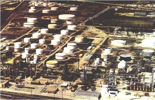
30 Tank Farm
31 Tanks - Cone Roof Typically Design Pressure < 2 psig, but usually 2.5 Inches Water gauge Ensure Vapour Pressure of Liquid is sufficiently low (suggest < half D.P.)

32 Storage Tanks - Cone Roof Conservation Vent

33 Tanks - Floating Roof Suitable for fluids with vapour pressures up to about 8 psig Floating Roof pontoons Edge Seal

34 Tanks - Spheres Suitable for Design Pressures of 2 to 15 psig 30 to 220 psig (Ludwig)

35 Tanks - Bullet Tanks Any Pressure
36 Workshop Vap Rate: Liq Rate: Vap Density: Liq Density: Size the Flasher V allowable := k ρ L ρ v ρ v /2 feed nozzle OD (48 min) V design := ( 75 % ) V allowable Size 50% Liq Hold-up for 10 min /2 feed nozzle OD (18 min) vol dia π dia 2 vol 4 π 3 2 ( 3 dia) 1 3
37 end
38 questions types of trays horiz vs vertical reactors lifter roof? Margin of error on flows

39 Reflux Drums (HYSYS) The Volume Liquid Rate Into the Drum - Careful of your simulator flows Give 20% excess for start-up