NEUTRAL GROUNDING TRANSFORMERS INSTALLATION AND MAINTENANCE INSTRUCTIONS
|
|
|
- Juliet Palmer
- 6 years ago
- Views:
Transcription
1 1
2 Table of Contents SECTION 1 Unpacking Shipping Receiving... 3 SECTION 2 Installation... 3 SECTION 3 Inspection... 4 SECTION 4 Connection Neutral Lead Ground Lead... 6 SECTION 5 Maintenance/Inspection
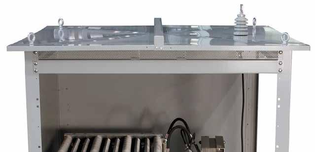
3 Section 1 Unpacking 1.1 Shipping Post Glover neutral grounding assemblies are placed in their normal mounting position onto a wooden skid and securely fastened to the skid with lag bolts. The units are then covered with plastic to protect the finish and to prevent dirt or moisture buildup that can occur during shipping or storage. Wooden supports are used inside the enclosure to support the resistor banks and/or transformer. Finally, the units are skid-mounted. All units are loaded by forklift into the enclosed van of a common carrier. At that point, it is the responsibility of the carrier to provide proper care in shipping and handling. 1.2 Receiving Once received, the skid-mounted unit should be unloaded and moved by forklift. At this point, a preliminary inspection of the unit should be made to ensure proper handling was practiced during shipment. It is recommended that the unit remain on the skid until it reaches the job site to prevent possible damage during transfer. All skid-mounted neutral grounding assemblies are suitable for prolonged storage. If the unit is to be stored, it should sit horizontally (as shipped). Never store the unit on the sides or top as this could result in damage to the bushings or insulators. Do not stack. Section 2 Installation When the unit arrives at the job site, remove the lag bolts which fasten the resistor unit to the skid. NOTE: It is recommended that all packing material within the enclosure remain intact until the unit is installed. Top-mounted eye-bolts are provided for easy hoisting and placement by crane. Post Glover neutral grounding assemblies can be mounted on a concrete pad or support stand near the transformer if the unit s size and weight permit. It is important that the enclosure be mounted horizontally (as shipped). This keeps the unit drip-proof, allows for adequate cooling, and prevents unnecessary strain on the support insulators. The unit should be bolted to the mounting surface using the holes provided at the bottom of each enclosure leg. Expansion-type anchors are recommended for concrete pad mounting. NOTE: The enclosure should always be securely grounded to prevent a shock hazard to personnel or wildlife. 3
4 Section 3 Inspection After the unit has been securely mounted and grounded, remove the front panel to allow inspection and wiring. The front panel can be identified by the Post Glover nameplate. REMOVE ALL PACKING MATERIAL, IF ANY, USED TO PROTECT THE INSULATORS, RESISTOR BANKS AND TRANSFORMER DURING SHIPMENT. NOTE: It is important that all packing material be removed from within the enclosure before energizing. FAILURE TO REMOVE THIS MATERIAL MAY RESULT IN FIRE HAZARD. With all packing material removed, carefully inspect the inside of the unit for broken insulators, bushings and other parts that may have been damaged during shipment. NOTE: If any damaged parts are found, contact the carrier immediately. ENERGIZING THE UNIT WITH DEFECTIVE PARTS MAY DAMAGE THE RESISTOR AND CREATE A SHOCK HAZARD TO PERSONNEL. CHECK ALL ELECTRICAL CONNECTIONS TO ENSURE THAT THEY ARE TIGHT. Section 4 Connection 4
 2.")
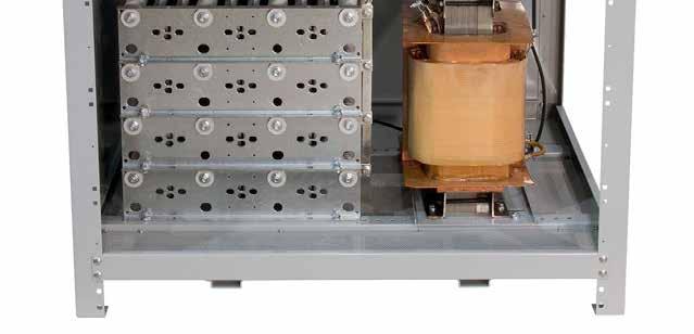
5 4.1 Neutral Lead The neutral lead from the transformer or generator may be connected one of two ways depending upon the specific design: 1. The connection is made directly to a top-mounted entrance bushing. The bushing has a NEMA two-hole pad-type connector. (See Figure 1.) 2. With the cables entering via rigid conduit entering from the bottom of the enclosure, the neutral connection is made directly on the H1 terminal of the grounding transformer. A compression type lug or NEMA 2/4 hole pad is used for terminal connection. Alternately, the lug or terminal may be mounted on a stand-off insulator to simplify installation. Location and termination of the conduit is the customer s responsibility. (See Figure 2.) Customer requested options and/or physical configurations may require unique termination methods, Consult the factory drawings for job-specific details. One terminal from the resistor assembly is shorted to the transformer s H2 terminal. Check this connection for tightness and integrity before energization. In all cases, the neutral terminal is tagged for easy identification and the proper connection is shown schematically on the drawing. CHECK TO SEE THAT ALL CONNECTIONS ARE FIRMLY TIGHTENED. * CONSULT LOCAL AND NEC CODES FOR PROPER CABLE SIZING. CONDUIT Figure 1: Bushing entry Figure 2: Bottom entry 5
6 4.2 Ground Lead The ground lead from the H2 terminal of the transformer to ground may be connected one of two ways: 1. For assemblies with bottom entering cables, the connection is made directly to the transformer s H2 terminal inside the enclosure via rigid conduit. The ground terminal is tagged for easy identification. A compression-type lug (or 2/4 hole pad) is used for the terminal connection. Location and termination of conduit is the customer s responsibility. (See Figure 3.) 2. The connection is made directly to a top-mounted exit bushing. The bushing has a NEMA two-hole pad type connector. The bushing will be factory wired to the transformer terminal. (See Figure 4.) In both cases, the ground terminal is tagged for easy identification and the proper connection is shown schematically on the drawing. CHECK TO SEE THAT ALL CONNECTIONS ARE FIRMLY TIGHTENED. CONDUIT Figure 3: Bottom entry Figure 4: NEMA two-hole pad 6
7 Section 5 Maintenance/Inspection Normally, no maintenance is necessary on a neutral grounding resistor. However, periodic inspections for damage are needed to ensure that the resistor is still capable of protecting the system. Damage may occur from lightening, storms, earthquakes, wildlife, overloads or extended service life. Basically, it is necessary to ensure that the resistive element has not burned open and that the element (including the incoming bushing) is still properly isolated from ground. The following procedure is recommended for periodic field inspections: 1. De-energize the system being grounded and break the connection between the system, the neutral, and the grounding resistor. An isolation switch is sometimes available to break this connection. These precautions are recommended to prevent a shock hazard to maintenance personnel and to prevent the system from being operated without proper grounding. 2. Remove the front cover (which is on the same side as the nameplate) and the rear cover. This will allow for a visual inspection of all internal components. 3. Carefully check for cracked insulators or bushings. A MEGGER or HI-POT test is the most reliable method of ensuring that the porcelain insulation is still providing the necessary electrical isolation. 4. Check the resistive elements for continuity. An ohmmeter reading made between the neutral and the ground side of the resistor should be within 10% of the nameplate value. If the resistance of the element is more than 15% off from the nameplate value, the resistors should be replaced. Any open resistors should be replaced. COMPLETE NAMEPLATE DATA WILL BE NECESSARY TO OBTAIN REPLACEMENT PARTS. 5. Check all internal connections for tightness. Check wiring for signs of damage from heat or overloads. 6. Vacuum any dirt or debris from the inside of the enclosure. 7. Check the enclosure for signs of damage from weather or rodents. Replace all side covers removed during inspection and check the mounting bolts for tightness. 8. FOR REPLACEMENT PARTS OR ASSISTANCE, CALL FOR MORE INFORMATION ABOUT POST GLOVER RESISTORS, OR TO PLACE AN ORDER, CALL
Ground Fault Protection. Medium Voltage Artificial Neutrals
 Ground Fault Protection Medium Voltage Artificial Neutrals Installation and Maintenance Instruction Manual 7615 Kimbel Street, Mississauga, Ontario Canada L5S 1A8 Tel: (905)673-1553 Fax: (905)673-8472
Instruction Manual. Ventilated Dry-Type Transformers. 600 Volts & Below
 Instruction Manual Ventilated Dry-Type Transformers 600 Volts & Below Instructions for the Safe Handling, Installation, Operation and Maintenance of Ventilated Dry-Type Transformers Table of Contents Paragraph
Bulk Bag Unloader Installation, Operation and Maintenance Manual
 Web-Tech Australia Pty Ltd Bulk Bag Unloader Installation, Operation and Maintenance Manual Web-Tech Australia Pty Ltd Manufacturers & Suppliers of Weighing, Level & Batching Equipment 11 Electronics Street
XAP Series Busduct Storage, Installation, and Maintenance
 Instruction Booklet IB Joint cover Tap-off Units Contents Description Introduction............................................................... Receiving...............................................................
SECTION LOW-VOLTAGE TRANSFORMERS
 PART 1 GENERAL 1.1 DESCRIPTION SECTION 26 22 00 SPEC WRITER NOTE: Use this section only for NCA projects. Delete between // // if not applicable to project. Also, delete any other item or paragraph not
Houston First Corporation Package 1 SECTION MEDIUM VOLTAGE FUSED SWITCH INTERRUPTER
 PART 1 - GENERAL 1.1 SUMMARY SECTION 26 13 16 MEDIUM VOLTAGE FUSED SWITCH INTERRUPTER A. The scope of this section includes providing and assembling materials and equipment for the dead-front, medium voltage
SECTION MOTOR CONTROL CENTER
 SECTION 16445 MOTOR CONTROL CENTER PART 1 GENERAL 1.01 DESCRIPTION A. This section covers the contract item Motor Control Center (MCC). The contract item includes demolition and removal of existing MCC;
Maintenance Bypass Breaker Cabinet Series Configuration 2. Installation and Operation Manual
 Maintenance Bypass Breaker Cabinet 90881 Series Configuration 2 Installation and Operation Manual 03/13/2012 2 755-00084-C2 R03 Copyright 2012 C&C Power, Inc. All rights reserved. C&C Power, Inc. 395 Mission
Installation and Operation Manual
 Installation and Operation Manual Maintenance Bypass Panel Model: SU2030KMBP Tripp Lite follows a policy of continuous improvement. Product specifications are subject to change without notice. 1111 West
Maintenance Bypass Breaker Cabinet Series Configuration 5. Installation and Operation Manual
 Maintenance Bypass Breaker Cabinet 90881 Series Configuration 5 Installation and Operation Manual 03/13/2012 2 755-00084-C5 R03 Copyright 2012 C&C Power, Inc. All rights reserved. C&C Power, Inc. 395 Mission
WL Switchgear. Instruction and Installation Guide. 11-C Rev. 4. usa.siemens.com/switchgear
 WL Switchgear Instruction and Installation Guide 11-C-9100-01 Rev. 4 usa.siemens.com/switchgear Hazardous voltage. Will cause death of serious injury. DANGER Keep out. Qualified personnel only. Disconnect
SECTION SECONDARY UNIT SUBSTATIONS
 SECTION 26 12 16 SECONDARY UNIT SUBSTATIONS PART 1 GENERAL 1.1 SUMMARY This section describes metal-clad, indoor or outdoor, secondary unit substations with integral primary fused disconnect switches,
ELECTRICAL SAFETY Information Bulletin
 ELECTRICAL SAFETY Information Bulletin February 2019 Page 1 of 5 2018 CANADIAN ELECTRICAL CODE SUBJECT: Section 6 Services and service equipment Rule 6-102 Number of supply services permitted Row housing
A. Section includes busway and fittings including plug-in units.
 SECTION 26 25 00 ENCLOSED BUS ASSEMBLIES PART 1 - GENERAL 1.1 SUMMARY A. Section includes busway and fittings including plug-in units. 1.2 REFERENCES A. Institute of Electrical and Electronics Engineers:
PACKAGED SYSTEMS INSTALLATION INSTRUCTIONS
 PACKAGED SYSTEMS INSTALLATION INSTRUCTIONS NOTE! To the installer: Please make sure you provide this manual to the owner of the equip ment or to the responsible party who maintains the system. Part #FMF-03-333
A. Provide a complete Distribution Panelboard system as indicated on the drawings, and as specified herein.
 16470 PANELBOARDS ************************************************************************************************************* SPECIFIER: CSI MasterFormat 2004 number: 26 24 16 An optional keynote to
V 2.0 ASSEMBLY GUIDE. TS Platform Scale Series 2
 V 2.0 ASSEMBLY GUIDE Series 2 TABLE OF CONTENTS OVERVIEW General Specifications...1 Cautions and Disclaimers...1 Contents of Kit...1 Tools Required For Assembly...2 Time Required to Assemble...2 ASSEMBLING
Equipment Specifications Low Voltage. Active Harmonic Filter
 Equipment Specifications Low Voltage Active Harmonic Filter 1.0 General Description This section contains the design standards, general equipment type and configuration, components, product description,
SECTION ENCLOSED BUS ASSEMBLIES
 SECTION 262500 ENCLOSED BUS ASSEMBLIES PART 1 - GENERAL 1.1 RELATED DOCUMENTS A. Drawings and general provisions of the Contract, including General and Supplementary Conditions and Division 01 Specification
Model: 770 Light Vehicle Scale Size: 8 x30 x5 Size: 10 x30 x5 Capacity: 40K CLC: 20K Capacity: 60K CLC:30K Installation, Set-Up and Operation Manual
 SCALE WORKS, INC. Model: 770 Light Vehicle Scale Size: 8 x30 x5 Size: 10 x30 x5 Capacity: 40K CLC: 20K Capacity: 60K CLC:30K Installation, Set-Up and Operation Manual Cambridge Scale Works, Inc. P.O. Box
Low Voltage Switchgear Construction Checklist (under 500 kva)
") Low Voltage Switchgear Checklist (under 500 kva) Project: Building: Location: Submittal / Approvals Submittal. The above equipment and systems integral to them are complete and ready for functional testing.
Low Voltage Switchgear Checklist (under 500 kva) Project: Building: Location: Submittal / Approvals Submittal. The above equipment and systems integral to them are complete and ready for functional testing.
SECTION BUSWAYS
 PART 1 - GENERAL 1.1 DESCRIPTION SECTION 26 25 11 BUSWAYS SPEC WRITER NOTE: Delete between //----// if not applicable to project. Also delete any other item or paragraph not applicable to the section and
MANUFACTURING TECHNICAL INSTRUCTIONS SAFETY Subject: DESIGN, MAINTENANCE AND INSPECTION OF SECONDARY ELECTRICAL DISTRIBUTION SYSTEMS
 DAIMLERCHRYSLER MANUFACTURING TECHNICAL INSTRUCTIONS SAFETY Subject: DESIGN, MAINTENANCE AND INSPECTION OF SECONDARY ELECTRICAL DISTRIBUTION SYSTEMS ISSUE DATE: 5/1/90 EFFECTIVE DATE: 2/4/92 REVIEW DATE:
SECTION ENCLOSED BUS ASSEMBLIES
 PART 1 - GENERAL 1.1 RELATED DOCUMENTS A. Drawings and general provisions of the Contract, including General and Supplementary Conditions, apply to this Section. 1.2 SUMMARY A. This Section includes the
ELECTRICAL SAFETY INSPECTION REPORT
 ELECTRICAL SAFETY INSPECTION REPORT AG s APPARELS LIMITED. Plot No. A/1&2 Block-B, BSCIC I/A Fouzderhat, Sagarika Road, Dhaka-1207, Bangladesh Factory List: 1. AG s Apparels Limited. Inspected by: Sherub
SIEMENS. Instructions. Outdoor Metal Clad Switchgear. Installation Assembly OGM&SGM SG kV and 15kV. www. ElectricalPartManuals.
 SIEMENS Outdoor Metal Clad Switchgear 5kV and 15kV Instructions Installation Assembly OGM&SGM SG 3258-00 THIS EQUIPMENT CONTAINS HAZARDOUS VOLTAGES. SEVERE PERSONAL INJURY OR PROPERTY DAMAGE CAN RESULT
MIRUS International Inc.
 MIRUS International Inc. INSTALLATION, OPERATION AND MAINTENANCE GUIDE AUTOTRANSFORMER AND UNIVERSAL HARMONIC FILTER IMPORTANT SAFETY INSTRUCTION SAVE THESE INSTRUCTIONS - This manual contains important
Legacy Environmental Process, LLC 1445 Ashville Road, Suite 103 Leeds, Alabama In USA Fax:
 Legacy Environmental Process, LLC 1445 Ashville Road, Suite 103 Leeds, Alabama 35094 In USA 1-205-640-1035 Fax: 1-205-640-1039 www.legacyenvpro.com Pre-Plant Delivery And Installation Manual For Project
Unit Substation Transformer Construction Checklist (under 500 kva)
") Unit Substation Transformer Checklist (under 500 kva) Building: Location: Submittal / Approvals Submittal. The above equipment and systems integral to them are complete and ready for functional testing.
Unit Substation Transformer Checklist (under 500 kva) Building: Location: Submittal / Approvals Submittal. The above equipment and systems integral to them are complete and ready for functional testing.
SECTION AUTOMATIC TRANSFER SWITCH
 SECTION 26 36 23 AUTOMATIC TRANSFER SWITCH PART 1: GENERAL 1.01 SCOPE A. Furnish all labor, materials, equipment and appurtenances, install and test electrically operated, automatic transfer switch (ATS)
SECTION GROUNDING
 SECTION 16450 GROUNDING PART 1 - GENERAL 1.1 DESCRIPTION A. This section specifies general grounding and bonding requirements of electrical and telecommunication installations for personnel safety, equipment
THE. Unitized Advantage
 THE Unitized Advantage The BCi Unitized Advantage Packaging & Delivery 1. Identification Prior to packaging, each panel or item is marked with a unique alphanumeric identifier corresponding to a unique
MATERIAL AND WORKMANSHIP
 PURCHASING AND PROCUREMENT DIVISION City of Jacksonville Beach Purchasing and Procurement Division 1460A Shetter Avenue Jacksonville Beach FL 32250 Phone: 904.247.6229 Fax: 904.247.1639 Email: purchasing
SPECIFICATION FOR SIMPLEX SWITCHBOARDS
 SPECIFICATION FOR SIMPLEX SWITCHBOARDS 1.0 SCOPE This specification presents general guidelines, design criteria, and construction requirements for AZZ ENCLOSURE SYSTEMS SIMPLEX PANELS for providing control
CONSTRUCTION SPECIFICATION FOR THE INSTALLATION OF SIGN LUMINAIRES
 ONTARIO PROVINCIAL STANDARD SPECIFICATION METRIC OPSS 612 SEPTEMBER 1984 CONSTRUCTION SPECIFICATION FOR THE INSTALLATION OF SIGN LUMINAIRES 612.01 SCOPE 612.02 REFERENCES 612.03 Not Used 612.04 Not Used
OVERHEAD SERVICES - RESIDENTIAL & GENERAL SERVICE. See Chapter 3, Section 3.01 for more information about point of entrance (POE).
.") 6.01 GENERAL OVERHEAD SERVICES - RESIDENTIAL & GENERAL SERVICE See Chapter 3, Section 3.01 for more information about point of entrance (POE). In all cases, the customer installs, owns, and maintains the
6.01 GENERAL OVERHEAD SERVICES - RESIDENTIAL & GENERAL SERVICE See Chapter 3, Section 3.01 for more information about point of entrance (POE). In all cases, the customer installs, owns, and maintains the
WALL CANTILEVER WORK STATION JIB CRANE
 SECTION 14662 WALL CANTILEVER WORK STATION JIB CRANE ***** Gorbel, Inc. manufactures a broad range of material handling cranes including monorail, bridge, gantry, and jib cranes. Numerous work station
Power Electronics, Inc. Packaged Equipment Center Standard Construction and Design Features
 DESIGN CRITERIA FOR STANDARD CONSTRUCTION: These standard design elements of the P.E.I. Power Equipment Center are utilized to meet the following design criteria per ASCE 7-05 as adopted by the IBC (International
OPERATING PROCEDURE NO. 310
 OPERATING PROCEDURE NO. 310 Related Operating Procedures: 310A; 310B; 310C; 310D SUBJECT: Conditions of Service Issued: February 10, 2014 Revised: March 28, 2016 OBJECTIVE: To establish the rules, regulations
UNDERGROUND SERVICES SECONDARY
 Reference UNDERGROUND SERVICES SECONDARY Underground services secondary... U- 1 General requirements for underground service... U- 2 Name of parts for underground service... U- 3 Conduit layouts... U-
This guide can be used to prepare a specification for incorporating wall bracket jib cranes into a competitively bid construction project.
 SECTION 14654 WALL BRACKET JIB CRANE ***** Gorbel, Inc. manufacturers a broad range of material handling cranes including monorail, bridge, gantry, and jib cranes. Numerous work station and industrial
1 29SEP03 ALL General update with miscellaneous changes in entire document.
 REVISION RECORD SECTION 16461 Dry-Type Transformers (600 V and Less) REV DATE PAGE PARA NO. DESCRIPTION APPROVED BY 28SEP01 ALL Initial issue. 1 29SEP03 ALL General update with miscellaneous changes in
Welcome to Douglas County PUD
 Welcome to Douglas County PUD We are committed to providing the best possible utility services at the lowest possible cost consistent with sound business principles. To better serve you, please fill out
Gerber. Scientific Products. Dear Gerber Sabre Customer:
 Gerber Scientific Products 151 Batson Drive, Manchester, CT 06040 (860) 643-1515 Dear Gerber Sabre Customer: Thank you for purchasing the Sabre, Gerber Scientific Products advanced, high-speed, three-dimensional
Instruction and Installation Guide usa.siemens.com/switchgear
 Front Connected Type WL Low Voltage Switchgear Instruction and Installation Guide usa.siemens.com/switchgear Hazardous voltage. Will cause death of serious injury. Keep out. Qualified personnel only. Disconnect
ADDENDUM NO. 1 BID AND CONTRACT DOCUMENTS FOR. BID No. 2019PW299
 ADDENDUM NO. 1 BID AND CONTRACT DOCUMENTS FOR BID No. 2019PW299 CHAFFEY COMMUNITY COLLEGE DISTRICT TRANSFORMER REPLACEMENT PROJECT RANCHO CUCAMONGA, CALIFORNIA COUNTY OF SAN BERNARDINO CHAFFEY COMMUNITY
B. Provide liquid-filled secondary substation transformers as indicated on drawings.
 SECTION 26 12 13 PART 1 - GENERAL 1.01 WORK INCLUDED A. Comply with the provisions of Sections 26 05 00. B. Provide liquid-filled secondary substation transformers as indicated on drawings. 1.02 RELATED
UNIFIED FACILITIES GUIDE SPECIFICATIONS. Use for Southeast projects only **************************************************************************
 USACE / NAVFAC / AFCESA / NASA UFGS-26 13 00.00 25 (July 2006) ------------------------------- Preparing Activity: NAVFAC Superseding Southeast UFGS-S-16345N (March 2001) Use in lieu of UFGS-26 13 00.00
INSTALLATION INSTRUCTIONS FOR ELECTRICAL CONTRACTORS
 INSTALLATION INSTRUCTIONS FOR ELECTRICAL CONTRACTORS Rev. 1.5 1.10.13 Toll free (800) 288-6000 or www.hubbell-wiring.com P a g e 0 IMPORTANT SAFETY INSTRUCTIONS SAVE THESE INSTRUCTIONS WARNING- When using
Installation, Inspection and Maintenance of Dry Type Transformers
 Dry Type TX 1 of 8 Installation, Inspection and Maintenance of Dry Type Page 1 of 8 Dry Type TX 2 of 8 Table Of Contents Page Number 1. General... 3 2. Installation... 3 3. Safety Inspections... 4 4. Safety
for Phoenix II-1 Human Cremation Retort
 Installation Manual for Phoenix II-1 Human Cremation Retort Please Read Carefully Before Installing. Any Questions? Please Call! Failure to install properly may VOID your warranty. NOTICE: Specifications
ELECTRICAL SERVICE REQUIREMENTS FOR MOBILE HOME DEVELOPMENTS
 Greenbook Prepared by: ABB1 ELECTRICAL SERVICE REQUIREMENTS FOR MOBILE HOME DEVELOPMENTS 052521 Asset Type: Electric Metering Function: Construction Issued by: Quoc Hoang (QxH1) Date: 08-15-17 Rev. #06:
Thimbles and Roof Jacks
 Industrial Silencer, Heat Recovery and Catalytic Specialists Maxim Silencers Thimbles and Roof Jacks Installation and Operation Manual NOTICE The instructions herein must be expressly carried out in order
for BLP 200/75 Animal Cremation Retort
 Installation Manual for BLP 200/75 Animal Cremation Retort Please Read Carefully Before Installing. Any Questions? Please Call! Failure to install properly may VOID your warranty. NOTICE: Specifications
Festoon Manual Heavy Duty C-Track
 Festoon Manual Heavy Duty C-Track 966300.3 Heavy Duty C-Track Manual CONDUCTIX INCORPORATED The technical data and images which appear in this manual are for informational purposes only. NO WARRANTIES,
Shur-Shot X-Proof Hydrogen Fluoride Alarm Operations Manual
 Shur-Shot X-Proof Hydrogen Fluoride Alarm Operations Manual P/N 1000006053 Rev E $7%$QDO\WLFV// //& 733 Dairy Rd. Parkton, Md. 21120 www.atbanalytics.com (410) 733-6365 Table of Contents Chapter 1: Getting
CHAPTER 13 GROUNDING AND BONDING
 GROUNDING AND BONDING CHAPTER 13 GROUNDING AND BONDING Grounding and bonding must be in accordance with Article 250 of the National Electrical Code (NEC). Bonding is defined in the NEC as the permanent
PD6770 VANTAGEVIEW LOOP-POWERED PROCESS METER
 PD6770 VANTAGEVIEW LOOP-POWERED PROCESS METER 4-20 ma input 1 V drop (4 V with Backlight) 3½ Digits LCD, 1" High Loop-Powered Backlight Option HART Protocol Transparent Plastic NEMA 4X, IP65 Enclosure
SECTION CONDUITS AND BACKBOXES FOR COMMUNICATIONS SYSTEMS
 SECTION 16711-27 05 28.33 PART 1 - GENERAL 1.01 SUMMARY A. This section includes Labor, materials and equipment necessary to complete the installation required for the items specified under this Section,
Solar Powered TS1000 Installation Pictures. (Trench and Fill Method) City of Vallejo, CA
 City of Vallejo, CA") Solar Powered TS1000 Installation Pictures (Trench and Fill Method) City of Vallejo, CA 12/04/09 Page 1 Pre-installation Phase 1. Main system components arrive on one or more pallets. 2. Optional pole
Solar Powered TS1000 Installation Pictures (Trench and Fill Method) City of Vallejo, CA 12/04/09 Page 1 Pre-installation Phase 1. Main system components arrive on one or more pallets. 2. Optional pole
Bravo Platform Unpacking Guide
 This guide describes how to unpack the Bravo device from the shipping carton. Depending on the order, the shipment can include additional packages for the Bravo utilities, pipetting head, computer, and
MREC March, 2005 Powering the Dairy Industry
 Mark A. Cook Manager Licensed Designer of Engineering Systems Certified Commercial and UDC Electrical Inspector Certified Master Electrician Public Service Commission of Wisconsin mark.cook@starband.net
2-Position T1/HDSL Environmental Mounting Assembly Model EM02-0xx
 General Description & Installation Practice EM02-0xx Rev. A. August 2008 680-00032 2-Position T1/HDSL Environmental Mounting Assembly Model EM02-0xx Table of Contents Page 1. General.......................
CONTENTS. B. System Design and Performance Requirements
 16060 Grounding and Bonding This document provides design standards only, and is not intended for use, in whole or in part, as a specification. Do not copy this information verbatim in specifications or
Model: LoLander Series Truck Scale Model: LL FT Model: LL FT Installation, Set-Up and Operation Manual
 SCALE WORKS, INC. Model: LoLander Series Truck Scale Model: LL8035-10FT Model: LL8035-11FT Installation, Set-Up and Operation Manual Cambridge Scale Works, Inc. P.O. Box 670 Honey Brook, PA. 19344 (800)
UNDERGROUND SERVICES - GENERAL SERVICE AND MULTI-UNIT RESIDENTIAL
 UNDERGROUND SERVICES - GENERAL SERVICE AND MULTI-UNIT RESIDENTIAL 8.01 GENERAL This material is not intended to cover service from OPPD s network in the downtown Omaha area. See Chapter 12 for details
8. REVENUE METERING. Operational Excellence Model. 8.1 Introduction
 8. 8.1 Introduction The purpose of this section is to outline requirements of the customer, as set forth herein by PSEG Long Island, as they pertain to Electric Revenue Metering at Primary and Secondary
XPM 2. Reflow Soldering / Curing Systems. Site Preparation & Installation
 XPM 2 Reflow Soldering / Curing Systems Site Preparation & Installation Site Preparation & Installation 1 Revision Date: May 2004 Table of Contents SITE PREPARATION CHECKLIST 3 ROOM PLANNING 4 Oven Clearances
PRIMARY LINE EXTENSION
 PRIMARY LINE EXTENSION Installation of new electric service to an empty parcel/lot or extending a transformer to within 150' of proposed meter location. This includes installing a permanent branch, addition,
This guide can be used to prepare a specification for incorporating free standing jib cranes into a competitively bid construction project.
 SECTION 14651 FREE STANDING JIB CRANE ***** Gorbel, Inc. manufacturers a broad range of material handling cranes including monorail, bridge, gantry, and jib cranes. Numerous work station and industrial
OPO-SHORT Installation Instructions Manual Version
 10200 South Kedzie Avenue Evergreen Park, IL 60805 800.499.0400 708.499.0400 Fax 708.499.4620 OPO-SHORT Installation Instructions Manual Version OPO-1S, OPO-3S, OPO-4S PreSell Main Board (shown as Standard
PLANNING GUIDE FOR SINGLE CUSTOMER SUBSTATIONS SERVED FROM TRANSMISSION LINES
 Prepared by: NIB/EOB PLANNING GUIDE FOR SINGLE CUSTOMER SUBSTATIONS SERVED FROM TRANSMISSION LINES 05503 Department: Electric T&D Section: T&D Engineering and Technical Support Approved by: G.O. Duru (GOD)
ASSEMBLY INSTRUCTIONS for DATASAFE TM HX and HX FRONT TERMINAL UBC BATTERY RACKS
 US-HXRACK-IM-002 ASSEMBLY INSTRUCTIONS for DATASAFE TM HX and HX FRONT TERMINAL UBC BATTERY RACKS Read all instructions carefully and observe all warnings before installation. See Installation, Operation
LOW PROFILE FLOOR SCALE
 π LOW PROFILE FLOOR SCALE 1-800-295-5510 uline.com SITE SELECTION Select a site for your new floor scale where it is least likely to be damaged by fork trucks and other material handling devices. Floor
Electrical Metallic Tubing (EMT) Fittings
 Fittings") Suggested Specifications for Electrical Metallic Tubing (EMT) Fittings Series 2 Insulated EMT Connector (Raintight) (Compression Type) Series 20 EMT Coupling (Raintight) (Compression Type) Series 0 Pipe
Suggested Specifications for Electrical Metallic Tubing (EMT) Fittings Series 2 Insulated EMT Connector (Raintight) (Compression Type) Series 20 EMT Coupling (Raintight) (Compression Type) Series 0 Pipe
DISTRIBUTION TRANSFORMER SPECIFICATION #
 DISTRIBUTION TRANSFORMER SPECIFICATION #1212.03 15kV Single Phase Submersible Transformer Stainless Steel 12/2/2011 Page 1 of 8 1. SCOPE This specification covers single-phase submersible transformers
An altered service that is moved, upgraded (ex., 200 to 400 amp) or changed to meet today's standards for electric service.
 or changed to meet today's standards for electric service.") ALTERED SERVICE An altered service that is moved, upgraded (ex., 200 to 400 amp) or changed to meet today's standards for electric service. Customer Responsibilities Provide, install and maintain all required
ALTERED SERVICE An altered service that is moved, upgraded (ex., 200 to 400 amp) or changed to meet today's standards for electric service. Customer Responsibilities Provide, install and maintain all required
SERIES 800 / 810 SPECIFICATION 15KV & 25KV PADMOUNTED LIQUID-INSULATED VACUUM LOAD INTERRUPTER ASSEMBLIES
 SERIES 800 / 810 SPECIFICATION 15KV & 25KV PADMOUNTED LIQUID-INSULATED VACUUM LOAD INTERRUPTER ASSEMBLIES MANUALLY OPERATED / REMOTELY OPERATED DEAD FRONT PADMOUNTED SWITCHGEAR WITH VACUUM LOAD INTERRUPTING
RL8000HE/RL8500HE Load Cell Mounting Kit. Installation Guide
 RL8000HE/RL8500HE Load Cell Mounting Kit Installation Guide 63286 Contents 1.0 Introduction... 1 2.0 Mechanical Installation... 2 2.1 General Installation Guidelines for Tank Mounts...2 2.2 Installing
SPORTSBEAMS 1500 LED USER MANUAL SPORTSBEAMS LIGHTING, INC. v.1.0
 SPORTSBEAMS 1500 LED USER MANUAL v.1.0 SPORTSBEAMS LIGHTING, INC. 1.888.905.6680 WWW.SPORTSBEAMS.COM TABLE OF CONTENTS INTRODUCTION...1 SAFETY WARNINGS...2 POWER SUPPLY Wiring Diagram....3 Fuse Ratings....3
SECTION to 5000 AMPERE PLUG-IN AND FEEDER BUSWAYS - SPECTRA. A. Low-Voltage Plug-in Busway to 5000 ampere, 600 VAC
 PART 1 GENERAL A. The requirements of the Contract, Division 1, and Division 16 apply to work in this Section. 1.01 SECTION INCLUDES A. Low-Voltage Plug-in Busway - 225 to 5000 ampere, 600 VAC 1.02 RELATED
Unloading Handling Storage
 structurlam.com version 5.0, March 2017 INTRODUCTION What is CrossLam? CrossLam or otherwise known as Cross Laminated Timber (CLT) panels are produced from dried SPF lumber which are stacked together at
NORTHWESTERN UNIVERSITY PROJECT NAME JOB # ISSUED: 03/29/2017
 SECTION 26 1200 - MEDIUM-VOLTAGE TRANSFORMERS PART 1 - GENERAL 1.1 RELATED DOCUMENTS A. Drawings and general provisions of the Contract, including General and Supplementary Conditions and Division 01 Specification
CONSOLIDATED EDISON COMPANY OF NEW YORK, INC Van Dam Street Long Island City, NY ELECTRIC METER SHOP DEPARTMENT
 CONSOLIDATED EDISON COMPANY OF NEW YORK, INC. 48-05 Van Dam Street Long Island City, NY 11101 ELECTRIC METER SHOP DEPARTMENT METER ENGINEERING SPECIFICATION MES-350 REVISION 3 June 2016 EFFECTIVE DATE
SECTION GENERAL ELECTRICAL REQUIREMENTS PART 1- GENERAL
 1.01 DESCRIPTION SECTION 16000 GENERAL ELECTRICAL REQUIREMENTS PART 1- GENERAL A. This Section includes the general provisions applicable to electrical work and testing of the completed electrical systems.
ELECTRICAL SAFETY INSPECTION REPORT
 ELECTRICAL SAFETY INSPECTION REPORT M/S. PROUD TEXTILE Plot 31/A, BSCIC Industrial Estate, Fatullah, Narayanganj, Bangladesh Factory List: 1. Inspected by: Pema Wangdi Report Generated by: Pema Wangdi
CLARK PUBLIC UTILITIES TECHNICAL SPECIFICATIONS SINGLE-PHASE PADMOUNTED TRANSFORMERS
 CLARK PUBLIC UTILITIES TECHNICAL SPECIFICATIONS SINGLE-PHASE PADMOUNTED TRANSFORMERS Original Issue 1/84 Revised 1/91 Revised 6/02 Revised 11/05 Revised 11/09 Revised 1/12 Revised 11/12 Revised 5/14 Revised
A. This Section includes the following types of dry-type transformers rated 600 V and less, with capacities up to 1000 kva:
 SECTION 16461 - LOW-VOLTAGE TRANSFORMERS PART 1 - GENERAL 1.1 RELATED DOCUMENTS A. Drawings and general provisions of the Contract, including General and Supplementary Conditions and Division 1 Specification
Railroad Track Scale
 Installation & Service Manual Railroad Track Scale Model: 8710 2003 by Thurman Scale Company All rights reserved 50727 Issue #1 8/03 Amendment Record Railroad Track Scale Model: 8710 50727 Manufactured
Installation. Smart-UPS VT in Parallel kva 380/400/415 V 208/220 V 200/208 V
 Installation Smart-UPS VT in Parallel 10-40 kva 380/400/415 V 208/220 V 200/208 V Contents Safety... 1 IMPORTANT SAFETY INSTRUCTIONS - SAVE THESE INSTRUCTIONS.............................. 1 Prepare for
Car and Counterweight Frames
 Car and Counterweight Frames CAR FRAME (SLING) AND PLATFORM COUNTERWEIGHT FRAME Every attempt has been made to ensure that this documentation is as accurate and up-to-date as possible. However, Vertical
NEMA Standards Publication ANSI/NEMA PB
 ANSI Approval Date October 14, 2003 NEMA Standards Publication ANSI/NEMA PB 2.1-2002 General Instructions for Proper Handling, Installation, Operation, and Maintenance of Deadfront Distribution Switchboards
OKLAHOMA DEPARTMENT OF TRANSPORTATION SPECIAL PROVISION FOR BRIDGE NAVIGATION LIGHTING
 809-1(a-e) 09 OKLAHOMA DEPARTMENT OF TRANSPORTATION SPECIAL PROVISION FOR BRIDGE NAVIGATION LIGHTING These special provisions amend and where in conflict, supersede applicable sections of the 2009 Standard
ELECTRICAL SAFETY INSPECTION REPORT
 ELECTRICAL SAFETY INSPECTION REPORT ABIR FASHIONS Kutubail, Fatullah (Post Office Road), Narayangonj, Bangladesh Factory List: 1. Inspected by: Pema Wangdi & Mamun Report Generated by: Pema Wangdi Inspected
Electrical Metallic Tubing (EMT) Fittings
 Fittings") Suggested Specifications for Electrical Metallic Tubing (EMT) Fittings Series 2 Insulated EMT Connector (Raintight) (Compression Type) Series 20 EMT Coupling (Raintight) (Compression Type) Series 0 Pipe
Suggested Specifications for Electrical Metallic Tubing (EMT) Fittings Series 2 Insulated EMT Connector (Raintight) (Compression Type) Series 20 EMT Coupling (Raintight) (Compression Type) Series 0 Pipe
VSS-2 ½ D HIGH HEAD SUMP PUMP FREE STANDING
 Flows to 200 GPM. TDH to 95 Feet at 1750 RPM Free Standing or Guide Rail Design. Available in Standard Submersible or Explosion Proof Design. Provided with 25 feet of submersible motor power cable. Cast
Gerber M Series Site Requirements
 Gerber M Series Site Requirements Preparing for the arrival of your new machine. P rior to the arrival of your Gerber M Series Cutting System there are certain things you can prepare to facilitate a quick
OVERHEAD SERVICE. Table of Contents - Section 400
 OVERHEAD SERVICE Table of Contents - Section 400 PARAGRAPH 400.0 OVERHEAD SERVICES (0-600 VOLTS)... 1 400.1 GENERAL 1 400.2 IDENTIFICATION OF CONDUCTORS. 1 400.3 MAXIMUM SERVICE ENTRANCE CONDUCTOR SIZE
WHITE PAPER The Criticality of Proactive Maintenance on Isolated Phase Bus Duct Systems
 WHITE PAPER The Criticality of Proactive Maintenance on Isolated Phase Bus Duct Systems Introduction Isolated Phase Bus Duct (IPBD) is the main conduit for power distribution in a power generation facility.
NORTHWESTERN UNIVERSITY PROJECT NAME JOB # ISSUED: 03/29/2017
 SECTION 26 0526 - GROUNDING AND BONDING FOR ELECTRICAL SYSTEMS PART 1 - GENERAL 1.1 RELATED DOCUMENTS A. Drawings and general provisions of the Contract, including General and Supplementary Conditions