OPO-SHORT Installation Instructions Manual Version
|
|
|
- Louise Rice
- 6 years ago
- Views:
Transcription

1 10200 South Kedzie Avenue Evergreen Park, IL Fax OPO-SHORT Installation Instructions Manual Version OPO-1S, OPO-3S, OPO-4S PreSell Main Board (shown as Standard 4 column) For ALL service related issues Please call Florida Plastics: 8:30am 5:00pm CST/6:30am-3:00pm PST:
2 Introduction The OPO Drive Thru System is a triple dayparting menu board system that is used to display custom POP selections for your products. The system consists of Main boards and Presell boards. Getting Familiar with Terms OPO- 4 OPO-4HW OPO-3 OPO-1 4 Column, Standard, Manual Main Board 4 Column, Standard, High Wind, Manual Main Board 3 Column, Standard, Manual Main Board 1 Column, Standard, Manual Presell Board Each system comes broken down into a pedestal assembly, triangular columns, top tie beam & rain caps and hardware kits. See Spec Drawings for As Shipped. Identification of the columns for the boards is critical to operation & service. Please note below the labels associated with each column. The Labeling is Lane 1, Column 1 = L1C1. L1C1 L2C1 L1C2 L1C3 L1C4 L2C2 L2C3 L2C4 Main Board - Inside Lane PreSell Main Board - Outside Lane L1C5 Viewed from Customer s Vantage Point Front of Menu Boards (MAIN BOARDS SHOWN AS STANDARD 4 COLUMN FOR ILLUSTRATION PURPOSE) Please note: The OPO menu boards are suitable for wet locations. Protective blue tape is for shipping purposes only! After installation: Gently remove the protective plastic from the face of the door Gently remove the blue plastic/tape that protects the lamps and sockets during shipping. Page 2 of 25
3 Page 3 of 25
4 Page 4 of 25
5 Page 5 of 25

6 Safety Warning ALL INSTALLATION, SERVICE, AND MAINTENANCE MUST BE PERFORMED BY A QUALIFIED ELECTRICIAN This dayparting menu board is intended to be installed in accordance with the requirements of Article 600 of the National Electrical Code and/or other applicable local codes. This includes grounding and bonding of the menu board. Perform all installation, service, and maintenance in compliance with OSHA, local and safety codes. Turn off all power before installation or servicing this menu board system. Notify Florida Plastics (Customer ) immediately with any problems. Installation of this drive thru system has both mechanical and electrical work. Electric access to the main menu board is not only through the center of the foundation base plate, but there are multiple other locations. Tools Required ladder 10 level 3 screw drivers (flat & Philips), magnetic bit holder small tip / flat blade screw driver (jewelers) wire striper wire tape (pulling) permanent marking pen 3/8 nut driver adjustable wrench box end wrenches ¾, 9/16, 15/16 circuit tester seal tite whips conduit 12 AWG wire (minimum per McDonalds) Page 6 of 25
7 Page 7 of 25
8 Page 8 of 25
9 Page 9 of 25
10 Page 10 of 25
11 Site Prep Wiring Details NOTE: Validate the site is ready for this new product line. Page 11 of 25
12 Page 12 of 25
13 Installation Mechanical / Electrical Mounting PreSell Pedestal and Column Rear View Step 1 Install a leveling nut and washer over each anchor bolt. Step 2 Pull wiring thru conduit. ON DEMAND power Step 3 Install pedestal to fit over conduits and anchor bolts onto leveling washers- Level pedestal base and validate Note: Jog Switch opening to the REAR FEED WIRING UP THRU PEDESTAL AND OUT JOG SWITCH OPENING Refer to Wiring Schematic Details * Power Feed (AC) Wiring Schematic- see pg. 13 Validate pedestal is LEVEL Utilize pedestal slots to align board for best customer viewing! Completely tighten all double nuts on the anchor bolts. See exploded detail below. NUT NUT WASHER PEDESTAL BASE WASHER LEVELING NUT Page 13 of 25
14 Step 4 Mount Triangle Assembly Route 3 wires from triangle assembly down center pole thru jog switch opening. Tighten all ½ HS bolts /column hardware following hardware sequence below. Hardware Sequence Nut Lock washer Triangle base plate Pedestal cap plate Flat washer Bolt ON DEMAND power supply Note: Typical hardware configuration for all columns HIGH side faces to the front LONG end faces to the rear Refer to Wiring Schematic Details * Power Feed (AC) Wiring Schematic- see pg. 13 Step 5 Mount PS Raincap Beam Open door Remove 3/8 bolt from top of center post in triangle to secure Raincap to beam. Install Raincap Beam Re-install 3/8 bolt along with second 3/8 bolt from hardware kit. Completely tighten ½ pedestal mount bolts. Step 6 Secure Raincap to Raincap Beam using #10 Hardware: Provided in Hardware Kit Step 7 Wiring Termination Terminate and ground ON DEMAND power supply. Page 14 of 25
15 Installation Mechanical/ Electrical Mount Main Menu Board Pedestal and Columns Rear View ENSURE SELECTION OF MOUNTING HOLES IN PEDESTAL ALLOWS FOR PROPER SIGN SET BACK FROM ALL CURBS. IF THERE ARE NO OBSTRUCTIONS PLACE PEDESTAL AS FAR TO THE RIGHT AS POSSIBLE (FROM VIEWING FACE). Step 1 Install a leveling nut and leveling plate over each anchor bolt. Refer to Wiring Schematic Details * Power Feed (AC) Wiring Schematic- see pg. 13 ON DEMAND power supply Step 2 Pull wiring thru conduit. Step 3 Install pedestal to fit over conduits and anchor bolts onto leveling plates- Level pedestal base and validate Jog Switch opening to the REAR Feed wiring up thru pedestal and out Switch opening Page 15 of 25
16 FOUNDATION CONNECTION DETAIL Validate pedestal is LEVEL Utilize pedestal slots to align board for best customer viewing! Completely tighten all double nuts on the anchor bolts. See exploded detail below. NUT NUT LEVELING PLATE PEDESTAL BASE LEVELING PLATE LEVELING NUT On Demand power supply Step 4 Install Column #4 Mount triangle assembly to cap plate with hardware. Route 1 wire from triangle assembly down center pole thru adjacent jog switch opening. Leave hardware hand tightened until Rain Cap Beam has been installed. Page 16 of 25
17 Step 5 Install Triangles 3 thru 1 Repeat install sequence for Columns # 3, #2 and #1. Each column has AC Power Feed. Validate each column has been labeled accordingly. Leave ½ HS Bolts finger tight until Beam and Raincap are installed. HIGH side faces to the front LONG end faces to the rear Step 7 Install Rain Cap Secure Raincap to Raincap Beam using #10 Hardware: Provided in Hardware Kit Step 6 Install Rain Cap Beam Open door Remove 3/8 bolt from top of center post in triangle to secure Raincap to beam. Install Raincap Beam Re-install 3/8 bolt along with second 3/8 bolt from hardware kit. Completely tighten ½ triangle mount bolts. Repeat for ALL columns! Page 17 of 25
18 Step 8 Wiring Termination Terminate and ground ON DEMAND power supply thru ON/OFF switch. Refer to Wiring Schematic Details * Power Feed (AC) Wiring Schematic- see pg. 13 ON DEMAND Switch Blank Cover Access Cover Note the direction that the columns rotate (COUNTERCLOCKWISE) Page 18 of 25
19 Page 19 of 25
20 Page 20 of 25
21 Validation Checklist * Validate all components are functioning when system is powered up. 1. Locate both On Demand and Always On circuits at service panel. Must be labeled! Refer to page 13 - OIT Enclosure Termination Detail schematic. 2. Validate boards are fully lit. 3. Validate all TOP and BOTTOM bushings are current version. 4. Turn each column, one at a time, for B-L-S and lock into place validating pull pins are working correctly. 5. Installers to properly mark the Product or ID Label, located on the back of each column reflector. Installers need to identify and check: Product type (i.e., Automated or Manual) Product Line (OPO-1, OPO-2, OPO-3, OPO-4) Special Features (S= SHORT, HW=HIGH Wind Load) See sample label for more detail. Page 21 of 25
22 DISCUSSION WITH STORE STAFF NEVER turn 2 adjacent columns at the same time Post OIT magnet with contact phone number information in a convenient location for all staff. Page 22 of 25
23 OPO Outdoor Menu Board Parts Policy & Procedures As a contracted Outdoor Menu Board Sign Installer, you are required to purchase all parts from Florida Plastics International. Installing unauthorized parts into a Florida Plastics Outdoor Menu Board will void all installation and/or product warranties. Ordering Parts in Warranty Sign Installer should call Florida Plastics at for a Return Authorization Florida Plastics will generate a Call Tag to allow the Sign Installer to return defective part Part(s) will be shipped to the Sign Installer ( may be shipped to the McDonald s restaurant directly if communicated at the time of the order) Invoice sent to the Sign Installer Sign Installer packages defective part, calls to schedule pickup Defective part shipped back to Florida Plastics Florida Plastics receives RA and part and credits Sign Installer account If part received is not defective, the Sign Installer will be invoiced Ordering Non Warranty Parts Call Florida Plastics at to order part or FAX PO to Part(s) will be shipped to Sign Installer or contracted Service Provider (Part may be shipped to McDonald s restaurant directly if communicated at the time of the order) Invoice for the non-warranty part(s) will be sent to Sign Installer or contracted Service Provider Sign Installer or contracted Service Provider will invoice the restaurant directly for any associated labor, travel, parts charges. Page 23 of 25
24 Sign Installation Warranty Warranty Statement Florida Plastics requires the authorized Sign Installer to provide a 60 day installation warranty from the date of installation. The warranty provides that the OPO Menu Board was installed according to the Florida Plastics guidelines as outlined in the Installation Manual using Florida Plastics approved parts and materials. Failure to install per instructions will result in Installer liability. In the event that additional work and/or parts are required to properly install the sign, all incurred costs will be the responsibility of the Installer. Spare Parts see details on OPO Parts Policy & Procedures All parts must be provided by Florida Plastics. You may purchase an inventory of spare parts which will be credited as used and failed parts returned or You may order parts as needed from Florida Plastics. Installation Failure Cost Expectations If Florida Plastics receives a service call from a restaurant that is in the install warranty period, and determines that an on-site visit is needed, Florida Plastics will notify the Sign Company so that the service call can be dispatched to the original Sign Installer. If Florida Plastics responds to a service call and it is determined that the failure is the result of the installation workmanship and is within the warranty period of 60 days, the Sign Installer will reimburse Florida Plastics its actual labor costs, not to exceed $75 without prior authorization. The Sign Installer will also reimburse Florida Plastics actual travel costs up to $75 without prior authorization. Approval for all labor and travel expenses that exceed these caps will be requested of the Sign Installer, prior to any work being performed. Product Failure Cost Expectations During the warranty period, if it is determined that the failure is a product failure and not the result of the installation, Florida Plastics will reimburse the Sign Installer its actual labor costs, not to exceed $75 without prior authorization from Florida Plastics. Florida Plastics will also reimburse the Sign Installer actual travel costs up to $75 without prior authorization from Florida Plastics. All labor and travel expenses that exceed these caps must be pre-approved by Florida Plastics. Invoice must reference Florida Plastics initiated service call number. To all Installers: Please complete the Installation Close Out form on the following page. Fax completed form to Florida Thank you. Page 24 of 25
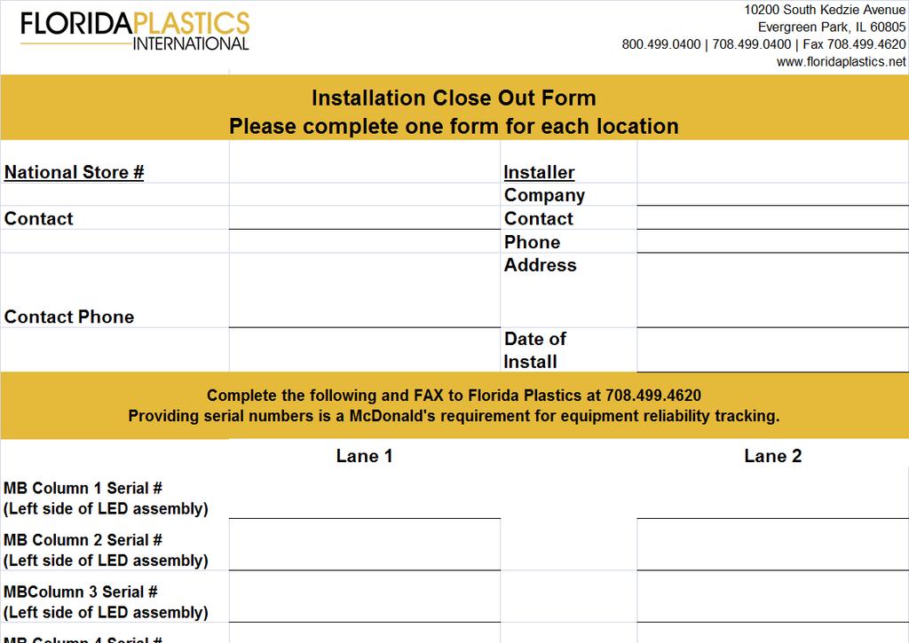
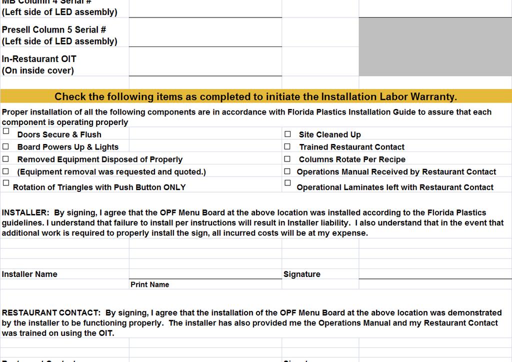
25 Installation Close Out Form Page 25 of 25
To Contact PS DOORS:
 MODELS Stainless Steel (SS) Powder Coat Yellow (PCY) Hot Dipped Galvanized (GAL) TABLE OF CONTENTS PAGE Warranty Information General Paired LSG Information Installing the Support Channels 3 Installing
VERsacourt LED Light System Installation Instructions
 VERsacourt LED Light System Installation Instructions PART LIST TEE BAR ASSEMBLY 10 12 LIGHT ASSEMBLY (hardware included) EXTENSION COLLAR BASE POLE EXTENSION POLE ANCHOR PAGE 1 REQUIRED TOOLS AND MATERIALS
MODEL GEK E3 Guard Enclosure Kit. Operator s Manual for Morse Guard Enclosure Kit Model GEK E3 for Can Tumbler Model E3
 Contents Page Receiving Procedures.................... 1 Warranty............................. 1 Safety Information..................... 1-2 Assembly Instructions................... 3-7 Parts List and
MODEL GEK E1 Guard Enclosure Kit. Operator s Manual for Morse Guard Enclosure Kit Model GEK E1 for Can Tumbler Model E1
 Contents Page Receiving Procedures.................... 1 Warranty............................. 1 Safety Information..................... 1-2 Assembly Instructions................... 3-7 Parts List and
Troubleshooting Guide 9702 Series
 Troubleshooting Guide 9702 Series Satellite Solutions for Mobile Markets 11200 Hampshire Avenue South, Bloomington, MN 55438-2453 Phone: (800) 982-9920 Fax: (952) 922-8424 www.kingcontrols.com 1305-AUTO
OWNER S MANUAL SERIES MDS-96-BK, SM, DR
 VESTIL MANUFACTURING CORP. 2999 N. Wayne St., Angola, IN 46703 Ph: 260-665-7586 Fax: 260-665-1339 E-mail: sales@vestil.com Website: www.vestil.com SERIES MDS-96-BK, SM, DR OWNER S MANUAL Introduction...
OWNER S MANUAL SERIES MDS-96-BK, SM, DR
 SERIES MDS-96-BK, SM, DR OWNER S MANUAL Introduction... 1 Bill of Materials... 2 Assembly Instructions. 3 Warranty....12 IMPORTANT NOTES, WARNINGS AND SAFETY INSTRUCTIONS Ensure that all employees understand
V 2.0 ASSEMBLY GUIDE. TS Platform Scale Series 2
 V 2.0 ASSEMBLY GUIDE Series 2 TABLE OF CONTENTS OVERVIEW General Specifications...1 Cautions and Disclaimers...1 Contents of Kit...1 Tools Required For Assembly...2 Time Required to Assemble...2 ASSEMBLING
Installation Instructions/Operation and Maintenance Manual. Models PLG-60 PLG-72. PS DOORS Contact Information. Website psdoors.
 Rev. 091416 Pallet Gate Installation Instructions/Operation and Maintenance Manual Models PLG-60 PLG-72 Table of Contents Product Information...2 Installation Instructions...3 Operation...6 Inspection
APL-2647 ADJUSTABLE SUSPENSION ADAPTER
 INSTALLATION MANUAL APL-2647 ADJUSTABLE SUSPENSION ADAPTER Premier Mounts 3130 E. Miraloma Avenue Anaheim, CA 92806 Phone: (800) 368-9700 Fax: (800) 832-4888 mounts@mounts.com www.mounts.com 9533-006-011-00
Universal Elevator Mount Owners Manual
 REQUIRED TOOLS AND MATERIALS: 2 Capable Adults Universal Elevator Mount Owners Manual 1-00-spalding Carpenter s Level 15 Tape Measure Pencil Adult Assembly Required. This manual, accompanied by sales receipt,
UNIVERSAL UTILITY TRUCK RACK
 UNIVERSAL UTILITY TRUCK RACK Owner s Manual WARNING: Read carefully and understand all ASSEMBLY AND OPERATION INSTRUCTIONS before operating. Failure to follow the safety rules and other basic safety precautions
Risk of fire and electrical shock. DISCONNECT POWER AT ELECTRICAL PANEL before installing or servicing this product.
 INSTALLATION INSTRUCTIONS RAIL 2 RM2D T-BAR LED NOTE: The following instructions provide general guidelines for product installation. For additional information consult the applicable electrical codes
CA11 11 Column. Operator s Manual. To Purchase This Item, Visit BMI Gaming LIMITED WARRANTY
 LIMITED WARRANTY Seaga warrants to the original purchaser that the equipment is free from defects in material and factory workmanship for a period of one (1) year from date of shipment. Repair or replacement
INSTALLATION MANUAL. All Types F Series Rev G
 INSTALLATION MANUAL All Types - 1570 F Series Page 1 of 16 TABLE OF CONTENTS DESCRIPTION PAGE GENERAL INFORMATION & ADVISORIES 2 PRODUCT INFORMATION 3 GET TO KNOW YOUR CBU 4 HARDWARE AND COMPONENTS 5 CONCRETE
GROUND MOUNT INSTALLATION MANUAL
 GROUND MOUNT INSTALLATION MANUAL Contents DISCLAIMER 1 CHECKLIST 2 1. ERECT BASe 3 2. CONNECT PIPES 3 3. PLACE RAILS 4 4. SECURE LUGS 4 5. CLAMP MODULES 5 DIAGONAL BRACES (OPTIONAL) 6 UNDER CLAMPS (OPTIONAL)
HATCHSAFE Installation Instructions/Operation and Maintenance Manual Models: All Models
 HATCHSAFE Installation Instructions/Operation and Maintenance Manual Models: All Models Contact Information Table of Contents: Safety Precautions... 2 Product Information... 2 Installation Instructions...
Instructions for the use of the Link 4 Pallet Rack Lifter (PRL) model 5000
 model 5000") Instructions for the use of the Link 4 Pallet Rack Lifter (PRL) model 5000 (How to move your pallet racking using the Link 4 Pallet Rack Lifter) This process is for a typical rack move and reset. Each
Instructions for the use of the Link 4 Pallet Rack Lifter (PRL) model 5000 (How to move your pallet racking using the Link 4 Pallet Rack Lifter) This process is for a typical rack move and reset. Each
General Guidelines. Tools Required. Safety. Deluxe Steel Folding Scooter & Wheelchair Carrier Instructions for Part # SC500-V3
 Deluxe Steel Folding Scooter & Wheelchair Carrier Instructions for Part # SC500-V3 General Guidelines It is the user s responsibility to read and follow all instructions. Keep these instructions with the
ROOF MOUNT KIT OWNERS MANUAL
 ROOF MOUNT KIT OWNERS MANUAL Made in the USA by: Southwest Windpower, Inc. 1801 W. Route 66 Flagstaff, Arizona 86001 Phone: (928) 779-9463 Fax: (928) 779-1485 E-mail: info@windenergy.com Web: www.windenergy.com
PD6770 VANTAGEVIEW LOOP-POWERED PROCESS METER
 PD6770 VANTAGEVIEW LOOP-POWERED PROCESS METER 4-20 ma input 1 V drop (4 V with Backlight) 3½ Digits LCD, 1" High Loop-Powered Backlight Option HART Protocol Transparent Plastic NEMA 4X, IP65 Enclosure
General Guidelines. Tools Required. Instructions for Part # SC500-AF. Safety
 Instructions for Part # SC500-AF General Guidelines It is the user s responsibility to read and follow all instructions. Keep these instructions with the product at all times and review before each use.
INSTALLATION INSTRUCTIONS FOR ELECTRICAL CONTRACTORS
 INSTALLATION INSTRUCTIONS FOR ELECTRICAL CONTRACTORS Rev. 1.5 1.10.13 Toll free (800) 288-6000 or www.hubbell-wiring.com P a g e 0 IMPORTANT SAFETY INSTRUCTIONS SAVE THESE INSTRUCTIONS WARNING- When using
Quick Adjustable Height Stands
 Quick Adjustable Height Stands Installation, Maintenance & Parts Manual DORNER MFG. CORP. INSIDE THE USA OUTSIDE THE USA P.O. Box 0 975 Cottonwood Ave. TEL: -800-397-8664 TEL: 6-367-7600 Hartland, WI 5309-000
McGUIRE MTR-3B MECHANICAL VEHICLE RESTRAINT WITH COMMUNICATION LIGHT SYSTEM OWNER'S MANUAL & INSTALLATION GUIDE
 McGUIRE MTR-3B MECHANICAL VEHICLE RESTRAINT WITH COMMUNICATION LIGHT SYSTEM OWNER'S MANUAL & INSTALLATION GUIDE IMPORTANT: Thoroughly read and understand entire contents of this manual prior to installation
FIXED CEILING COLUMN. Installation Manual FIXED CEILING COLUMN
 FIXED CEILING COLUMN Installation Manual FIXED CEILING COLUMN INTRODUCTION Location, sequence of services and orientation of Surgical Ceiling Columns are specified on the building plans. Be certain installation
PAIRED LADDER SAFETY GATE Installation Instructions/Operation and Maintenance Manual
 PAIRED LADDER SAFETY GATE Installation Instructions/Operation and Maintenance Manual Models: All Models Contact Information Table of Contents: Safety Precautions... 2 Product Information... 2 Support Channel
10810 W. LITTLE YORK RD. #130 - HOUSTON, TX VOICE (713) FAX (713) web: IMPORTANT!!!
 FAX (713) web: IMPORTANT!!!") 10810 W. LITTLE YORK RD. #130 - HOUSTON, TX 77041-4051 VOICE (713) 973-6905 FAX (713) 973-9352 web: www.twrlighting.com IMPORTANT!!! PLEASE TAKE THE TIME TO FILL OUT THIS FORM COMPLETELY. FILE IT IN A
10810 W. LITTLE YORK RD. #130 - HOUSTON, TX 77041-4051 VOICE (713) 973-6905 FAX (713) 973-9352 web: www.twrlighting.com IMPORTANT!!! PLEASE TAKE THE TIME TO FILL OUT THIS FORM COMPLETELY. FILE IT IN A
1-300 SERIES Endover Rotator Operator s Manual for Morse End-Over-End Drum Rotators Series
 Contents Page Receiving Procedures.................... 1 Warranty............................. 1 Safety Information..................... 1-2 Machine Description................... 3 Operating Instructions....................
General Guidelines. Tools Required. Steel Folding Scooter & Wheelchair Carrier Instructions for Part # SC400-V2. Safety
 Steel Folding Scooter & Wheelchair Carrier Instructions for Part # SC400-V2 General Guidelines It is the user s responsibility to read and follow all instructions. Keep these instructions with the product
SERVICE PEDESTAL FLOOR-MOUNTED SERVICE PEDESTAL. Installation Manual
 SERVICE PEDESTAL Installation Manual FLOOR-MOUNTED SERVICE PEDESTAL Figure 1. DEFINITION OF STATEMENTS Statements in this manual preceded by the following words are of special significance: WARNING: Means
STP Mount Series. Installation Manual. STP-LSCR-MAN 2017 Edition v1.0. For models: STP-SCR/045 STP-SCR/060 STP-SCR/070 STP-LCR/090 STP-LCR/120
 Installation Manual STP-LSCR-MAN 2017 Edition v1.0 For models: STP-SCR/045 STP-SCR/060 STP-SCR/070 STP-LCR/090 STP-LCR/120 Table of Contents Introduction... 1 Customer Support... 1 Tools Required... 2
Model: LoLander Series Truck Scale Model: LL FT Model: LL FT Installation, Set-Up and Operation Manual
 SCALE WORKS, INC. Model: LoLander Series Truck Scale Model: LL8035-10FT Model: LL8035-11FT Installation, Set-Up and Operation Manual Cambridge Scale Works, Inc. P.O. Box 670 Honey Brook, PA. 19344 (800)
PV Mounting System 2703 SERIES 200 UL GROUND MOUNT SYSTEM. SnapNrack Residential PV Mounting Systems Code Compliant Installation Manual
 PV Mounting System 2703 SERIES 200 UL GROUND MOUNT SYSTEM SnapNrack Residential PV Mounting Systems Code Compliant Installation Manual Series 200 UL Introduction Series 200 UL Introduction SnapNrack Series
ISIMET. E Series Enclosure. Custom Assemblies Installation, Maintenance, and Operation Instructions
 ISIMET E Series Enclosure Custom Assemblies Installation, Maintenance, and Operation Instructions The Custom Assembled E-Series Enclosures is pre-assembled and pre-wired enclosure intended for use with
Installation. Smart-UPS VT in Parallel kva 380/400/415 V 208/220 V 200/208 V
 Installation Smart-UPS VT in Parallel 10-40 kva 380/400/415 V 208/220 V 200/208 V Contents Safety... 1 IMPORTANT SAFETY INSTRUCTIONS - SAVE THESE INSTRUCTIONS.............................. 1 Prepare for
ROOF MOUNT KIT OWNERS MANUAL
 ROOF MOUNT KIT OWNERS MANUAL Made in the USA by: Primus Wind Power, Inc. 938 Quail St. Lakewood, CO 80215 Phone: (303) 242-5820 www.primuswindpower.com AIR is a trademark of Primus Wind Power, Inc. ROOF
C Series Mechanical Pit Levelers. P.O. Box 338 Spring Hill, Tennessee fax:
 C Series Mechanical Pit Levelers SM P.O. Box 338 Spring Hill, Tennessee 37174 1-800-251-3382 fax: 931-486-0316 www.pioneerleveler.com DO NOT install, operate or service product unless you have read and
INSTRUCTION MANUAL SHELF FLOOR LAMP
 INSTRUCTION MANUAL SHELF FLOOR LAMP A: Cushion B: Shade C: Allen Screw D: Thick Board 4pcs 1pc 8pcs 1pc E: Long Poles F: Thin Board G: Board with Lamp Kit H: Short Poles 12pcs 2pcs 1SET I: Square Frame
This guide can be used to prepare a specification for incorporating wall bracket jib cranes into a competitively bid construction project.
 SECTION 14654 WALL BRACKET JIB CRANE ***** Gorbel, Inc. manufacturers a broad range of material handling cranes including monorail, bridge, gantry, and jib cranes. Numerous work station and industrial
Fun Industries Inc. G100D Grabber Deluxe Operation Instructions
 Fun Industries Inc. G100D Grabber Deluxe Operation Instructions After removing all protective film from the machines walls and decals, the following pages will guide you through the process of assembling,
PAIRED LADDER SAFETY GATE Installation Instructions/Operation and Maintenance Manual
 PAIRED LADDER SAFETY GATE Installation Instructions/Operation and Maintenance Manual Contact Information Models: DBLLSG-9-GAL to DBLLSG-24-GAL DBLLSG-9-PCY to DBLLSG-24-PCY DBLLSG-9-SS to DBLLSG-24-SS
LADDER SAFETY GATE Installation Instructions/Operation and Maintenance Manual
 LADDER SAFETY GATE Installation Instructions/Operation and Maintenance Manual Models: All Models Contact Information Table of Contents: Safety Precautions... 2 Product Information... 2 Operation... 3 Standard
MODELS MB1K-1, MB1K-2 MB2K-1, MB2K-2 MB3K-1, MB3K-2
 FALCON ELECTRIC INC. OWNER S MANUAL SG Series Maintenance Bypass Option 1KVA 3KVA MODELS MB1K-1, MB1K-2 MB2K-1, MB2K-2 MB3K-1, MB3K-2 OM48030 Rev. B 01/17/03 FALCON Electric Inc., 5106 Azusa Canyon Road,
Quick-release pins swing the rack open from left to right to simplify installing and maintaining your equipment.
 RM070A-R3 RM080A-R3 Wallmount Frame User s Manual Quick-release pins swing the rack open from left to right to simplify installing and maintaining your equipment. Customer Support Information Order toll-free
Installation and Operation Manual
 Installation and Operation Manual Maintenance Bypass Panel Model: SU2030KMBP Tripp Lite follows a policy of continuous improvement. Product specifications are subject to change without notice. 1111 West
SECTION GENERAL ELECTRICAL REQUIREMENTS PART 1- GENERAL
 1.01 DESCRIPTION SECTION 16000 GENERAL ELECTRICAL REQUIREMENTS PART 1- GENERAL A. This Section includes the general provisions applicable to electrical work and testing of the completed electrical systems.
Thank you for purchasing the SC-CONVERSION System 500/600 Conversion Kit. This Kit is available in two different versions:
 Rev. 1 (Jun 30, 2016) Thank you for purchasing the SC-CONVERSION System 500/600 Conversion Kit. This Kit is available in two different versions: Part # 4K01328-FI SC-CONVERSION Conversion Kit with MEI
H07 H09. BENCH FUME HOOD with Combination Sash. Fume Hoods. Installation Instructions. 48"- 60"- 72"- 96" long
 Installation Instructions Supreme Air BENCH FUME HOOD with Combination Sash H07 H09 S T Y L E Fume Hoods 48"- 60"- 72"- 96" long Publication No. IIH07-SA 07/06 Part Number: IMAN-H07 FUME HOOD END PANEL
Ultra-Thin LED/LCD TV Mount 23" to 42" Installation Guide
 Ultra-Thin LED/LCD TV Mount 23" to 42" Installation Guide Ultra-Thin LED/LCD TV Wall Mount Material: 2.0mm Cold Rolled Steel Plate TV size: 23" - 42" Max load capacity: 110 lbs / 50 kgs Wall distance:
Model # 800SM-PS3. 8/3/2016 Page 1 of 8
 Model # 800SM-PS3 8/3/2016 Page 1 of 8 /3/2016 Page 2 of 8 1675 Locust Street Red Bud, IL 62278 Phone: 618-282-8200 Fax: 618-282-8202 WARRANTY & TERMS WARRANTY: 5 Year Limited Warranty on Thermoplastic
Instruction Manual TWISTLOCK SAND VOLLEYBALL SOCKETS SVB23/SVB27
 Instruction Manual TWISTLOCK SAND VOLLEYBALL SOCKETS Customer Service (800) 247-7668 SVB23/SVB27 P A R T S L I S T Item Qty Description Item Qty Description A 1 Sand Volleyball Socket (3 or 4 ) B 1 Twistlock
Y SIDE ALUMINUM TRUCK RACK
 Y SIDE ALUMINUM TRUCK RACK Owner s Manual WARNING: Read carefully and understand all ASSEMBLY AND OPERATION INSTRUCTIONS before operating. Failure to follow the safety rules and other basic safety precautions
Bravo Platform Unpacking Guide
 This guide describes how to unpack the Bravo device from the shipping carton. Depending on the order, the shipment can include additional packages for the Bravo utilities, pipetting head, computer, and
Universal Tilting TV Mount 32" to 60" Installation Instructions
 Universal Tilting TV Mount 32" to 60" Installation Instructions Tiltable LCD / TFT TV Wall Mount Material: 2.0mm Cold Rolled Steel Plate TV size: 32" - 60" Tilt angle: 0-15 degrees Max load capacity: 165
TABLE OF CONTENTS. Vacuum Cleaner. Model No. MC-CG Bagless Canister Red North America
 Order No.: MAC1412002CE Vacuum Cleaner Model No. MC-CG902-02 Bagless Canister Red North America TABLE OF CONTENTS PAGE 1 Specifications ----------------------------------------------------- 2 2 Disassembly
U-LAP. UTR-30 & UTR-70 Recipro Air Lappers Repair Manual. BORIDE Engineered Abrasives 2615 Aero Park Dr. Traverse City, MI
 U-LAP UTR-30 & UTR-70 Recipro Air Lappers Repair Manual UTR-20-30-70 Repair Instruction Manual Repair Instruction Manual Content Exploded View --------------------------------------------------------------------Page
XAP Series Busduct Storage, Installation, and Maintenance
 Instruction Booklet IB Joint cover Tap-off Units Contents Description Introduction............................................................... Receiving...............................................................
LINON HOME DECOR PRODUCTS, INC. ASSEMBLY INSTRUCTIONS LATTICE VANITY SET 58036SIL-01-KD-U
 ASSEMBLY INSTRUCTIONS LATTICE VANITY SET 58036SIL-0-KD-U PAGE OF 8 WE ARE HERE TO HELP! WE DO OUR BEST TO INSURE THAT YOUR FURNITURE ARRIVES IN EXCELLENT CONDITION. IN THE EVENT THAT A PART IS DAMAGED
H50. DYNAMIC BARRIER Bench Fume Hood. Fume Hoods. Installation Instructions. 48"- 60"- 72"- 96" long
 Installation Instructions Supreme Air DYNAMIC BARRIER Bench Fume Hood H50 S T Y L E Fume Hoods 48"- 60"- 72"- 96" long Publication No. IIH50-SA 06/01 Part Number: IMAN-H50 Kewaunee Scientific Corporation
NEUTRAL GROUNDING TRANSFORMERS INSTALLATION AND MAINTENANCE INSTRUCTIONS
 1 Table of Contents SECTION 1 Unpacking... 3 1.1 Shipping... 3 1.2 Receiving... 3 SECTION 2 Installation... 3 SECTION 3 Inspection... 4 SECTION 4 Connection... 4 4.1 Neutral Lead... 5 4.2 Ground Lead...
SIEMENS. Instructions. Outdoor Metal Clad Switchgear. Installation Assembly OGM&SGM SG kV and 15kV. www. ElectricalPartManuals.
 SIEMENS Outdoor Metal Clad Switchgear 5kV and 15kV Instructions Installation Assembly OGM&SGM SG 3258-00 THIS EQUIPMENT CONTAINS HAZARDOUS VOLTAGES. SEVERE PERSONAL INJURY OR PROPERTY DAMAGE CAN RESULT
10810 W. LITTLE YORK RD. #130 - HOUSTON, TX VOICE (713) FAX (713) web: IMPORTANT!!!
 FAX (713) web: IMPORTANT!!!") 10810 W. LITTLE YORK RD. #130 - HOUSTON, TX 77041-4051 VOICE (713) 973-6905 - FAX (713) 973-9352 web: www.twrlighting.com IMPORTANT!!! PLEASE TAKE THE TIME TO FILL OUT THIS FORM COMPLETELY. FILE IT IN
10810 W. LITTLE YORK RD. #130 - HOUSTON, TX 77041-4051 VOICE (713) 973-6905 - FAX (713) 973-9352 web: www.twrlighting.com IMPORTANT!!! PLEASE TAKE THE TIME TO FILL OUT THIS FORM COMPLETELY. FILE IT IN
Model # SV-R32AU. 2/13/2015 Page 1 of 11
 Model # SV-R32AU 2/13/2015 Page 1 of 11 /13/2015 Page 2 of 11 1675 Locust Street Red Bud, IL 62278 Phone: 618-282-8200 Fax: 618-282-8202 WARRANTY & TERMS WARRANTY: 5 Year Limited Warranty on Thermoplastic
Model: 770 Light Vehicle Scale Size: 8 x30 x5 Size: 10 x30 x5 Capacity: 40K CLC: 20K Capacity: 60K CLC:30K Installation, Set-Up and Operation Manual
 SCALE WORKS, INC. Model: 770 Light Vehicle Scale Size: 8 x30 x5 Size: 10 x30 x5 Capacity: 40K CLC: 20K Capacity: 60K CLC:30K Installation, Set-Up and Operation Manual Cambridge Scale Works, Inc. P.O. Box
Wall-Mount & Back to Wall Toilets
 Wall-Mount & Back to Wall Toilets Installation Guide FLOOR LW600 back to wall LW600 wall-mount FLOOR 05-04 Attention Before Installation If you are installing this product in a new construction or remodel,
2 HP SIMPLEX GRINDER PUMPS
 2 HP SIMPLEX GRINDER PUMPS INSTALLATION AND SERVICE MANUAL For 2 HP Simplex Grinder Pump with LiftOut Rail System Installed in Fiberglass Basin, at Factory, as Complete System or Parts for Installing in
2-Position T1/HDSL Environmental Mounting Assembly Model EM02-0xx
 General Description & Installation Practice EM02-0xx Rev. A. August 2008 680-00032 2-Position T1/HDSL Environmental Mounting Assembly Model EM02-0xx Table of Contents Page 1. General.......................
READ THIS MANUAL CAREFULLY BEFORE ASSEMBLY, TESTING & OPERATING
 The Operator must thoroughly read and understand this manual before operating the dust collector or commencing any servicing. Care should be taken to follow all safety rules and warning instructions. READ
FORM HEADWALL. FORM HEADWALL (floating) (floating) Installation Manual
 (floating) Installation Manual") FORM HEADWALL (floating) Installation Manual FORM HEADWALL (floating) OVERVIEW The Form is a UL-listed configurable headwall system. This system includes multiple horizontal equipment channels integrated
FORM HEADWALL (floating) Installation Manual FORM HEADWALL (floating) OVERVIEW The Form is a UL-listed configurable headwall system. This system includes multiple horizontal equipment channels integrated
Model # PR /21/2018 Page 1 of 10
 Model # PR-32 11/21/2018 Page 1 of 10 1/21/2018 Page 2 of 10 1675 Locust Street Red Bud, IL 62278 Phone: 618-282-8200 Fax: 618-282-8202 WARRANTY & TERMS WARRANTY: 5 Year Limited Warranty on Thermoplastic
Solar Powered TS1000 Installation Pictures. (Trench and Fill Method) City of Vallejo, CA
 City of Vallejo, CA") Solar Powered TS1000 Installation Pictures (Trench and Fill Method) City of Vallejo, CA 12/04/09 Page 1 Pre-installation Phase 1. Main system components arrive on one or more pallets. 2. Optional pole
Solar Powered TS1000 Installation Pictures (Trench and Fill Method) City of Vallejo, CA 12/04/09 Page 1 Pre-installation Phase 1. Main system components arrive on one or more pallets. 2. Optional pole
FORM FOOTWALL. FORM FOOTWALL (floating) (floating) Installation Manual
 (floating) Installation Manual") FORM FOOTWALL (floating) Installation Manual FORM FOOTWALL (floating) OVERVIEW The Form is a UL-listed configurable footwall system. This system can include any combination of base cabinets, upper cabinets,
FORM FOOTWALL (floating) Installation Manual FORM FOOTWALL (floating) OVERVIEW The Form is a UL-listed configurable footwall system. This system can include any combination of base cabinets, upper cabinets,
INSTALLATION MANUAL. FOOTWALL/SINKWALL (floor mount)
") INSTALLATION MANUAL FOOTWALL/SINKWALL (floor mount) OVERVIEW The Form is a UL-listed configurable footwall/sinkwall system. This system can include any combination of base cabinets, upper cabinets, wardrobes,
INSTALLATION MANUAL FOOTWALL/SINKWALL (floor mount) OVERVIEW The Form is a UL-listed configurable footwall/sinkwall system. This system can include any combination of base cabinets, upper cabinets, wardrobes,
Festoon Manual Heavy Duty C-Track
 Festoon Manual Heavy Duty C-Track 966300.3 Heavy Duty C-Track Manual CONDUCTIX INCORPORATED The technical data and images which appear in this manual are for informational purposes only. NO WARRANTIES,
Leveling Foot RB210. Leg Extender RLT66
 Landing for Right & Left Turn R342 ITEMS # 0254049, 0254061, 0254072, 0254076, 0016567, 0254099, 0254110, 0054116, 0254117, 0254126, 0254140, 0254150, 0254156 CUSTOM ACCESS RAMP SYSTEM MODELS # R100, R242,
Pallet Gate Installation Instructions and Operators Manual
 Pallet Gate Installation Instructions and Operators Manual Models PLG-6084 PLG-7284 PLG-6084-SST PLG-7284-SST Table of Contents Product Information...2 Installation Instructions...4 Parts and Reordering...7
MiT. MOVING image TECHNOLOGIES INSTRUCTIONS FOR INSTALLATION, OPERATION, AND MAINTENANCE. MPL Digital Pedestal. Manual Version 0.2
 MiT MOVING image TECHNOLOGIES INSTRUCTIONS FOR INSTALLATION, OPERATION, AND MAINTENANCE OF MPL Digital Pedestal Manual Version 0.2 MOVING image TECHNOLOGIES, LLC. 17760 Newhope St. Fountain Valley, CA
GC-X360S-W GC-X360S-B
 GC-X360S-W GC-X360S-B Game Console Security Cover for Xbox 360S 1 date:01/22/13 #:125-9401 WARNING ENG - This product was designed to be installed on wood stud, solid concrete or cinder block walls. Before
SYSTEM 600 BILL CHANGER INSTALLATION INSTRUCTIONS Congratulations...
 www.standardchange.com 1-800-968-6955 Technical Phone Support is from 8:00AM to 7:30PM E.S.T., Monday-Friday Walk-in Service is from 8:00AM to 4:30PM E.S.T., Monday-Friday Parts Department is from 8:00AM
Universal Projector Ceiling Mount - Black Installation Instructions
 Universal Projector Ceiling Mount - Black Installation Instructions Important Safety Information Use proper safety equipment during installation If you don't understand the installation instructions, have
FORM HEADWALL. FORM HEADWALL (floor mount) (floor mount) Installation Manual
 (floor mount) Installation Manual") FORM HEADWALL (floor mount) Installation Manual FORM HEADWALL (floor mount) OVERVIEW The Form is a UL-listed configurable headwall system. This system includes multiple horizontal equipment channels integrated
FORM HEADWALL (floor mount) Installation Manual FORM HEADWALL (floor mount) OVERVIEW The Form is a UL-listed configurable headwall system. This system includes multiple horizontal equipment channels integrated
Ceiling Camera Lift 2015
 Ceiling Camera Lift 2015 1 Contents Important Installation Notes 3 Control Settings 4 Installation 5 Physical Installation Top Mounting 6 Lift Connections / Connecting Power 8 Camera Mounting / Cabling
DETAIL INSTRUCTION No. 1
 BEFORE BEGINNING INSTALLATION, PLEASE READ THROUGH ALL INSTRUCTIONS. Uncrate shipment and check against packing list to insure all materials are included before beginning installation. If any discrepencies
Variable Speed Controller
 Installation, Maintenance and Parts Manual DORNER MFG. CORP. INSIDE THE USA OUTSIDE THE USA P.O. Box 20 975 Cottonwood Ave. TEL: -800-397-8664 TEL: 262-367-7600 Hartland, WI 53029-0020 USA FAX: -800-369-2440
KEEP FOR FUTURE REFERENCE MRT FORKLIFT ADAPTER READ ALL INSTRUCTIONS AND WARNINGS BEFORE USING THIS PRODUCT
 KEEP FOR FUTURE REFERENCE P.O. Box 368 908 West Main Laurel, MT USA 59044 phone 800-548-7341 phone 406-628-8231 fax 406-628-8354 INSTRUCTIONS International Version STOCK NUMBER: 95722 MRT FORKLIFT ADAPTER
HD Firewall Mount 850 all, S/V , C ipd #
 PI-394 10/10 Dedicated to improving vehicle fun, safety & performance Installation Instructions PI394 HD Firewall Mount 850 all, S/V70 1998-2000, C70 1998-2004 ipd #21.0001 SUGGESTED TOOLS Metric End Wrenches
A Collaborative Program of Arbor Day Foundation and Dimensions Educational Research Foundation. Tube Drums #7000. Assembly Instructions
 A Collaborative Program of Arbor Day Foundation and Dimensions Educational Research Foundation Tube Drums #7000 Assembly Instructions Please open and inspect all items upon receipt. If you have any questions
Duramax Storage Shed Limited Fifteen Year Warranty
 Duramax Storage Shed Limited Fifteen Year Warranty U.S. Polymer Inc. will send a replacement part free of charge, in the event of material defects and or workmanship for a period of fifteen years from
INSTALLATION GUIDE. 4-Post Lift. Model United States. United Arab Emirates. Egypt.
 4-Post Lift INSTALLATION GUIDE United States 17779 Main Street Suite C Irvine, CA 92614 USA Tel: +1(949) 333-3800 Fax: +1(949) 333-3804 United Arab Emirates Model 46614 P.O. Box 121971 Saif Zone A2-032
FITNESS PLAYGROUND ITEM NO: 8010
 FITNESS PLAYGROUND ITEM NO: 8010 OWNER S MANUAL CAUTION: This unit is designed to be used safely by up to 4 children between the ages of 3 years to 8 years old with a maximum weight of 100 pounds (45.4
ADJUSTABLE AIR HYDRAULIC SLIDING JACKBEAM 7000 lbs.
 ADJUSTABLE AIR HYDRAULIC SLIDING JACKBEAM 7000 lbs. (217) INSTALLATION AND OPERATION MANUAL SAVE ALL INSTRUCTIONS READ ALL INSTRUCTIONS THOROUGHLY BEFORE INSTALLING, OPERATING, SERVICING, OR MAINTAINING
National Vendors Changetron 2/4 Validator Installation Instructions
 National Vendors Changetron 2/4 Validator Installation Instructions Kit Overview This kit is designed to update National Vendors Changetron 2/4 dollar bill changers that use hopper drums to dispense coins.
Model # 238HS-P8. 4/27/2011 Page 1 of 11
 Model # 238HS-P8 4/27/2011 Page 1 of 11 4/27/2011 Page 2 of 11 1675 Locust Street Red Bud, IL 62278 Phone: 618-282-8200 Fax: 618-282-8202 WARRANTY & TERMS WARRANTY: 5 Year Limited Warranty on Thermoplastic
Drag Chain Conveyor Installation and Operation Manual
 Drag Chain Conveyor Installation and Operation Manual Material Handling Equipment Sales, Incorporated 310 S. Section Line Rd Delaware, OH 43015 Phone: (989) 430-4005 Fax: (740) 363-9004 WARRANTY MATERIAL
1.0. Post Install Kit. For Use With All Vinyl Railing BOM V1 1/13. Owner's Manual. Assembly and Installation Instructions.
 Post Install Kit Assembly and Installation Instructions PLEASE READ OWNER'S MANUAL COMPLETELY BEFORE ASSEMBLING YOUR POST INSTALL KIT. For Use With All Vinyl Railing 34106837BOM V1 1/13 Owner's Manual
PRB. Flush Mount Racking System. Installation Manual
 PRB Flush Mount Racking System Installation Manual Released 5th April 2015 TABLE OF CONTENTS 1. INTRODUCTION 1.1 Product Overview 1.2 About This Manual 1.3 Product Liability 1.4 Standards Compliance 1.5
L SERIES NEBS COMPLIANT STANDBY BATTERY RACKS ASSEMBLY INSTRUCTIONS
 RETURN RECYCLE RS 1942 LEAD L SERIES NEBS COMPLIANT STANDBY BATTERY RACKS ASSEMBLY INSTRUCTIONS General: These instructions detail the proper procedure for installing C&D Technologies' Powercom Division
78-RK VARIABLE SPEED HEAVY DUTY VIBRATOR OPERATING MANUAL
 78-RK VARIABLE SPEED HEAVY DUTY VIBRATOR OPERATING MANUAL IMPORTANT INSTRUCTIONS WARNING! FOR YOUR SAFETY PLEASE READ INSTRUCTIONS BEFORE OPERATING TOOL & WEAR EYE PROTECTION FD.08/2009 THANK YOU FOR PURCHASING
Operator s Manual for Morse Kontrol-Karrier with Spark Resistant Parts and Air Power Tilt
 Contents Page Receiving Procedures.................... 1 Warranty............................. 1 Safety Information..................... 1-2 Machine Description................... 2 Assembly Instructions..................