11.1.2* Adjacent Hazards or Design Methods. For buildings with two or more adjacent hazards or design methods, the following shall apply:
|
|
|
- Rosamund May
- 6 years ago
- Views:
Transcription
1 10 of /7/ :33 PM First Revision No. 260-NFPA [ Section No ] * Adjacent Hazards or Design Methods. For buildings with two or more adjacent hazards or design methods, the following shall apply: (1) Where areas are not physically separated by a draft curtain, barrier, or partition capable of delaying heat from a fire in one area from fusing sprinklers in the adjacent area, the required sprinkler protection for the more demanding design basis shall extend 15 ft (4.6 m) beyond its perimeter. (2) The requirements of (1) shall not apply where the areas are separated by a draft curtain, barrier, or partition that is capable of preventing delaying heat from a fire in one area from fusing sprinklers in the adjacent area. (3) The requirements of (1) shall not apply to the extension of more demanding criteria from an upper ceiling level to beneath a lower ceiling level where the difference in height between the ceiling levels is at least 2 ft (0.6 m). Submitter Information Verification Submitter Full Name: [ Not Specified ] Organization: [ Not Specified ] Street Address: City: State: Zip: Submittal Date: Mon Aug 26 14:53:09 EDT 2013 Committee Statement Committee Statement: The terminology between sections (1) and (2) needs to be consistent. One currently uses the terminology "delay" while the other uses the term "prevent". Since "prevent" has a more permanent connotation, its use here is inappropriate. The intent is to delay the operation of sprinklers in the remote area until sprinklers over the fire have had a chance to open. Response Message: Public Input No. 192-NFPA [Section No ]
2 11 of /7/ :33 PM First Revision No. 261-NFPA [ Section No ] Unless the requirements of are met, the minimum required discharge from each of the four hydraulically most demanding sprinklers design area sprinkler shall be the greater of the following: (1) In accordance with minimum flow rates indicated in individual the sprinkler listings (2) (3) Calculated based on delivering a minimum of 0.1 gpm/ft 2 (4.1 mm/min) over the design area in accordance with the provisions of or In rooms or compartments greater than 800 ft² (74.3 m 2 ), calculated based on delivering a minimum of 0.1 gpm/ft 2 (4.1 mm/min) over the design area in accordance with the provisions of In rooms or compartments 800 ft 2 (74.3 m 2 ) or less calculated based on delivering a minimum of 0.1 gpm/ft 2 (4.1 mm/min) over the room or the compartment using the area of the room divided by the number of sprinklers in the room Submitter Information Verification Submitter Full Name: [ Not Specified ] Organization: [ Not Specified ] Street Address: City: State: Zip: Submittal Date: Mon Aug 26 15:14:26 EDT 2013 Committee Statement Committee Statement: This section has been modified to incorporate the current requirements for average spacing of sprinklers in small rooms into this section. An annex section has been added to clarify how to calculate average spacing. Response Message: Public Input No. 4-NFPA [Section No ]
3 First Revision No. 190-NFPA [ New Section after ] For corrugated metal deck roofs up to 3 in. (76 mm) in depth, the maximum roof height shall be measured from floor to the bottom of the deck. Global FR-190 Hide Deleted For decks deeper than 3 in. (76 mm), the maximum roof height shall be measured to the highest point on the deck For ceilings that have insulation installed directly against underside of the ceiling or roof structure, the maximum roof height shall be measured to the bottom of insulation and shall be in accordance with or For insulation that is installed directly against the ceiling or roof structure and is installed flat and parallel to the ceiling or roof structure, the maximum roof height shall be measured to the underside of the insulation For insulation that is installed in a manner that causes it to deflect or sag down from the ceiling or roof structure, the maximum roof height shall be measured as half of the distance of the deflection from the insulation high point to the insulation low point. If the deflection or sag in the insulation exceeds 6 in. (152 mm), the maximum roof height shall be measured to the high point of the insulation. Submitter Information Verification Submitter Full Name: [ Not Specified ] Organization: [ Not Specified ] Street Address: City: State: Zip: Submittal Date: Sun Aug 25 12:03:44 EDT 2013 Committee Statement Committee Statement: Response Message: The maximum roof deck should be measured with regards to the same criteria applied to clearance to ceiling and deflector distance. Public Input No. 347-NFPA [New Section after ] 12 of /7/ :33 PM
4 13 of /7/ :33 PM First Revision No. 191-NFPA [ Section No ] The maximum building height shall be measured to the underside of the roof deck or ceiling or in accordance with through Global FR-190 Hide Deleted For corrugated metal deck roofs up to 3 in. (76 mm) in depth, the maximum roof height shall be measured from floor to the bottom of the deck For decks deeper than 3 in. (76 mm), the maximum roof height shall be measured to the highest point on the deck For ceilings that have insulation installed directly against underside of the ceiling or roof structure, the maximum roof height shall be measured to the bottom of insulation and shall be in accordance with or For insulation that is installed directly against the ceiling or roof structure and is installed flat and parallel to the ceiling or roof structure, the maximum roof height shall be measured to the underside of the insulation For insulation that is installed in a manner that causes it to deflect or sag down from the ceiling or roof structure, the maximum roof height shall be measured as half of the distance of the deflection from the insulation high point to the insulation low point. If the deflection or sag in the insulation exceeds 6 in. (152 mm), the maximum roof height shall be measured to the high point of the insulation. Submitter Information Verification Submitter Full Name: [ Not Specified ] Organization: [ Not Specified ] Street Address: City: State: Zip: Submittal Date: Sun Aug 25 12:06:31 EDT 2013 Committee Statement Committee Statement: Response Message: The maximum roof deck should be measured with regards to the same criteria applied to clearance to ceiling and deflector distance. Public Input No. 346-NFPA [Section No ]
5 14 of /7/ :33 PM First Revision No. 192-NFPA [ Section No ] 12.3* Adjacent Hazards or Design Methods. For buildings with two or more adjacent hazards or design methods, the following shall apply: (1) Where areas are not physically separated by a barrier or partition capable of delaying heat from a fire in one area from fusing sprinklers in the adjacent area, the required sprinkler protection for the more demanding design basis shall extend 15 ft (4.6 m) beyond its perimeter. (2) The requirements of 12.3(1) shall not apply where the areas are separated by a draft curtain, barrier, or partition that is capable of preventing delaying heat from a fire in one area from fusing sprinklers in the adjacent area. (3) The requirements of 12.3(1) shall not apply to the extension of more demanding criteria from an upper ceiling level to beneath a lower ceiling level where the difference in height between the ceiling levels is at least 2 ft (0.6 m). Submitter Information Verification Submitter Full Name: [ Not Specified ] Organization: [ Not Specified ] Street Address: City: State: Zip: Submittal Date: Sun Aug 25 12:08:41 EDT 2013 Committee Statement Committee Statement: The terminology between sections 12.3(1) and 12.3(2) needs to be consistent. One currently uses the terminology "delay" while the other uses the term "prevent". Since "prevent" has a more permanent connotation, its use here is inappropriate. All we are trying to do is delay the operation of sprinklers in the remote area until sprinklers over the fire have had a chance to open. The term draft curtain has been added to clarify that this is an acceptable means of delay sprinkler. Response Message: Public Input No. 193-NFPA [Section No. 12.3]
6 15 of /7/ :33 PM First Revision No. 193-NFPA [ Section No ] ESFR sprinklers shall only be permitted to be wet pipe systems. Submitter Information Verification Submitter Full Name: [ Not Specified ] Organization: [ Not Specified ] Street Address: City: State: Zip: Submittal Date: Sun Aug 25 12:19:22 EDT 2013 Committee Statement Committee Statement: Response Message: This section is unnecessary as section already addresses what types of systems can use ESFR sprinklers.
7 16 of /7/ :33 PM First Revision No. 194-NFPA [ Section No ] Densities and areas shall be selected so that the final area of operation after the 30 percent increase is not greater than 3900 ft 2 (360 m 2 ). Submitter Information Verification Submitter Full Name: [ Not Specified ] Organization: [ Not Specified ] Street Address: City: State: Zip: Submittal Date: Sun Aug 25 12:28:33 EDT 2013 Committee Statement Committee Statement: Response Message: The density/area curves only have a maximum 3,000 ft2 area on the curve, it is not possible to exceed this value when selecting a point on the curve.
8 17 of /7/ :33 PM First Revision No. 195-NFPA [ Section No [Excluding any Sub-Sections] ] CMSA and ESFR sprinklers shall be permitted to protect storage of Class I through Class IV commodities, Group A plastic commodities, miscellaneous storage, and other storage as specified in Chapter 12 through Chapter 20 or by other NFPA standards. Submitter Information Verification Submitter Full Name: [ Not Specified ] Organization: [ Not Specified ] Street Address: City: State: Zip: Submittal Date: Sun Aug 25 12:31:40 EDT 2013 Committee Statement Committee Statement: Response Message: This revision is offered to clarify, that the requirements are concerned with Group A plastics, as other types of plastics would be classified as Class III or Class IV commodities. Public Input No. 284-NFPA [Section No [Excluding any Sub-Sections]]
9 18 of /7/ :33 PM First Revision No. 196-NFPA [ Section No ] ESFR sprinklers designed to meet any criteria in Chapter 14 through Chapter 20 shall be permitted to protect light and ordinary hazard occupancies. any of the following: (1) Light hazard occupancies (2) Ordinary hazard occupancies (3) Any storage arrangement in Chapter 13 referencing OH1, OH2, EH1, and EH2 design criteria Submitter Information Verification Submitter Full Name: [ Not Specified ] Organization: [ Not Specified ] Street Address: City: State: Zip: Submittal Date: Sun Aug 25 12:40:20 EDT 2013 Committee Statement Committee Statement: Response Message: For limited amounts of storage within chapter 13 any ESFR design should provide adequate protection. Public Input No. 424-NFPA [Section No ]
10 19 of /7/ :33 PM First Revision No. 197-NFPA [ Section No ] Quick-response CMSA sprinklers designed to meet any criteria in Chapter 14 through Chapter 20 shall be permitted to protect light and ordinary hazard occupancies. any of the following: (1) Light hazard occupancies (2) Ordinary hazard occupancies (3) Any storage arrangement in Chapter 13 referencing OH1, OH2, EH1, and EH2 design criteria Submitter Information Verification Submitter Full Name: [ Not Specified ] Organization: [ Not Specified ] Street Address: City: State: Zip: Submittal Date: Sun Aug 25 14:48:30 EDT 2013 Committee Statement Committee Statement: For limited amounts of storage within chapter 13 any CMSA design should provide adequate protection. Response Message: Public Input No. 425-NFPA [Section No ]
11 20 of /7/ :33 PM First Revision No. 198-NFPA [ Section No ] Standard-response CMSA sprinklers designed to meet any criteria in Chapter 14 through Chapter 20 shall be permitted to protect ordinary hazard occupancies. any of the following: (1) Ordinary hazard occupancies (2) Any storage arrangement in Chapter 13 referencing OH1, OH2, EH1, and EH2 design criteria Submitter Information Verification Submitter Full Name: [ Not Specified ] Organization: [ Not Specified ] Street Address: City: State: Zip: Submittal Date: Sun Aug 25 14:49:50 EDT 2013 Committee Statement Committee Statement: For limited amounts of storage within chapter 13 any CMSA design should provide adequate protection. Response Message: Public Input No. 426-NFPA [Section No ]
12 21 of /7/ :33 PM First Revision No. 199-NFPA [ Section No ] Hydraulically Designed Occupancy Hazard Fire Control Sprinkler System. Unless indicated otherwise, the minimum water supply requirements for a hydraulically designed sprinkler system shall be determined by adding the hose stream allowance from Table to the water demand for sprinklers. Table Hose Stream Allowance and Water Supply Duration Sprinkler Type Control mode density/area CMSA ESFR Sprinkler Spacing Type Standard Standard and extendedcoverage Extendedcoverage Standard Number of Sprinklers in Design Area * NA Size of Design Area Up to 1200 ft 2 Hose Stream Allowance gpm L/min (111 m 2 ) Over 1200 ft 2 (111 m 2 ) up to 1500 ft 2 (139 m 2 ) Over 1500 ft 2 (139 m 2 ) up to 2600 ft 2 (240 m 2 ) Over 2600 ft 2 (240 m 2 ) Up to 12 NA Over 12 to 15 NA Over 15 to 25 NA Over 25 NA Up to 6 NA Up to ft 2 (13.4 m 2 ) maximum Over 6 to 8 NA Over 8 to 12 NA Over 12 NA Up to 12 NA Over 12 to 15 NA Over 15 to 25 NA Over 25 NA Water Supply Duration (minutes) NA: Not applicable. * For CSMA and ESFR sprinklers the additional sprinklers included in the design area for obstructions do not need to be considered in determining the total number of sprinklers in this column.
13 Unless indicated otherwise, the minimum water supply requirements for a hydraulically designed occupancy hazard fire control sprinkler system shall be determined by adding the hose stream allowance from Table to the water supply for sprinklers. Table Hose Stream Allowance and Water Supply Duration Sprinkler Type Sprinkler Spacing Type Number of Sprinklers in Design Area * Size of Design Area Hose Stream Allowance gpm L/min Water Supply Duration (minutes) Up to 1200 ft 2 (111 m 2 ) Over 1200 ft 2 (111 m 2 ) up to 1500 ft 2 (139 Control mode density/area Standard and extendedcoverage NA m 2 ) Over 1500 ft 2 (139 m 2 ) up to 2600 ft 2 (240 m 2 ) Over 2600 ft 2 (240 m 2 ) CMSA ESFR Standard Extendedcoverage Standard Up to 12 NA Over 12 to 15 NA Over 15 to 25 NA Over 25 NA Up to 6 NA ft 2 (13.4 Up to 8 m 2 ) maximum Over 6 to 8 NA Over 8 to 12 NA Over 12 NA Up to 12 NA Over 12 to 15 NA Over 15 to 25 NA Over 25 NA NA: Not applicable. * For CSMA and ESFR sprinklers the additional sprinklers included in the design area for obstructions do not need to be considered in determining the total number of sprinklers in this column Unless indicated otherwise, the supply determined in accordance with shall be available for the minimum duration specified in Table Submitter Information Verification Submitter Full Name: [ Not Specified ] 22 of /7/ :33 PM
14 23 of /7/ :33 PM Organization: [ Not Specified ] Street Address: City: State: Zip: Submittal Date: Sun Aug 25 14:51:40 EDT 2013 Committee Statement Committee Statement: Response Message: This section does not address occupancy hazard fire control, therefore this section needs to be revised and simplified to address water supply and duration requirements. Public Input No. 116-NFPA [Section No ]
15 24 of /7/ :33 PM First Revision No. 183-NFPA [ Section No [Excluding any Sub-Sections] ] When using the density/area method or room design method, unless the requirements of are met for buildings having unsprinklered combustible concealed spaces as described in and , the minimum area of sprinkler operation for that portion of the building shall be 3000 ft 2 (279 m 2 ). Submitter Information Verification Submitter Full Name: [ Not Specified ] Organization: [ Not Specified ] Street Address: City: State: Zip: Submittal Date: Sun Aug 25 10:59:36 EDT 2013 Committee Statement Committee Statement: Response Message: Ch 12 allows the room method to be used for storage applications, and as such this section must be updated to acknowledge this allowance.
16 25 of /7/ :33 PM First Revision No. 313-NFPA [ Section No ] The following unsprinklered combustible concealed spaces shall not require a minimum design area of sprinkler operation of 3000 ft 2 (279 m 2 ): (1) Noncombustible and limited-combustible concealed spaces with minimal combustible loading having no access. The space shall be considered a concealed space even with small openings such as those used as return air for a plenum. (2) Noncombustible and limited-combustible concealed spaces with limited access and not permitting occupancy or storage of combustibles. The space shall be considered a concealed space even with small openings such as those used as return air for a plenum. (3) Combustible concealed spaces filled entirely with noncombustible insulation. (4) Concealed spaces where rigid materials are used and the exposed surfaces have a flame spread index of 25 or less and the materials have been demonstrated to not propagate fire more than 10.5 ft (3.2 m) when tested in accordance with ASTM E 84, Standard Test Method for Surface Burning Characteristics of Building Materials, or ANSI/UL 723, Standard for Test for Surface Burning Characteristics of Building Materials, extended for an additional 20 minutes in the form in which they are installed in the space. (5) Concealed spaces in which the exposed materials are constructed entirely of fire retardant treated wood as defined by NFPA 703. (6) Concealed spaces over isolated small rooms compartments not exceeding 55 ft 2 (5.1 m 2 ) in area. (7) (8) * Light or ordinary hazard occupancies where noncombustible or limited-combustible ceilings are directly attached to the bottom of solid wood joists so as to create enclosed joist spaces 160 ft 3 (4.5 m 3 ) or less in volume, including space below insulation that is laid directly on top or within the ceiling joists in an otherwise sprinklered concealed space. Vertical pipe chases under 10 ft 2 (0.93 m 2 ), provided that in multifloor buildings the chases are firestopped at each floor using materials equivalent to the floor construction. Such pipe chases shall contain no sources of ignition, piping shall be noncombustible, and pipe penetrations at each floor shall be properly sealed. Exterior columns under 10 ft 2 (0.93 m 2 ) in area formed by studs or wood joists, supporting exterior canopies that are fully protected with a sprinkler system. * Light or ordinary hazard occupancies where noncombustible or limited-combustible ceilings are attached to the bottom of composite wood joists either directly or on to metal channels not exceeding 1 in. (25.4 mm) in depth, provided the adjacent joist channels are firestopped into volumes not exceeding 160 ft 3 (4.5 m 3 ) using materials equivalent to ½ in. (12.7 mm) gypsum board and at least 3½ in. (90 mm) of batt insulation is installed at the bottom of the joist channels when the ceiling is attached utilizing metal channels. Submitter Information Verification Submitter Full Name: Matthew Klaus Organization: National Fire Protection Assoc Street Address: City: State: Zip:
17 26 of /7/ :33 PM Submittal Date: Mon Sep 30 13:40:27 EDT 2013 Committee Statement Committee Statement: Response Message: This sections deals only with concealed spaces so we suggest to adjust the title even thought the companion section in Chapter 11 uses the term Restrictions. Also the section deals with storage so delete the references to light and ordinary hazard as they are covered in Chapter 11.
18 27 of /7/ :33 PM First Revision No. 200-NFPA [ Section No [Excluding any Sub-Sections] ] To utilize the room design method, all rooms shall be enclosed with walls having a fire resistance rating equal to the required water supply duration indicated in Chapters 13 through 20. Submitter Information Verification Submitter Full Name: [ Not Specified ] Organization: [ Not Specified ] Street Address: City: State: Zip: Submittal Date: Sun Aug 25 14:53:50 EDT 2013 Committee Statement Committee Statement: Response Message: Change needed to recognize the additional storage design approaches provided by Chapter 21. The reference to the specific chapters is unnecessary. Public Input No. 393-NFPA [Section No [Excluding any Sub-Sections]]
19 28 of /7/ :33 PM First Revision No. 265-NFPA [ Section No ]
20 29 of /7/ :33 PM Wood pallets, where stored indoors, shall be protected in accordance with one of the following: (1) Control mode density/area sprinkler protection as specified in Table (a). (2) CMSA sprinkler protection in accordance with Table (b). (3) ESFR sprinkler protection in accordance with Table (c). (4) Control mode density/area sprinkler protection in accordance with the OH2 curve of Figure existing with a hose stream demand of at least 250 gpm (946 L/min) for a duration of at least 60 minutes when pallets are stored no higher than 6 ft (1.8 m) and each pile of no more than four stacks shall be is separated from other pallet piles by at least 8 ft (1.4 m) of clear space or 25 ft (7.6 m) of commodity. The maximum clearance to ceiling of 20 ft (6.1 m) specified in shall not apply to arrangement (4). Table (a) Control Mode Density/Area Sprinkler Protection for Indoor Storage of Idle Wood Pallets Type of Sprinkler Control mode density/area Location of Storage On floor On floor On floor or rack without solid shelves On floor Nominal K-Factor 8 (115) or larger 11.2 (160) or larger 11.2 (160) or larger 16.8 (240) or larger Maximum Storage Height Maximum Celing/Roof Height Sprinkler Density Areas of Operation High Temperature Ordinary Temperature ft m ft m gpm/ft 2 mm/min ft 2 m 2 ft 2 m 2 Up to 6 Up to 8 8 to to 20 Up to 20 Up to 1.8 Up to to to 6.1 Up to Table (a) Control Mode Density/Area Sprinkler Protection for Indoor Storage of Idle Wood Pallets Type of Sprinkler Control mode density/area Location of Storage On floor On floor On floor or rack without solid shelves On floor Nominal K-Factor 8 (115) or larger 11.2 (160) or larger 11.2 (160) or larger 16.8 (240) or larger Maximum Storage Height Maximum Celing/Roof Height Sprinkler Density Areas of Operation ft m ft m gpm/ft 2 mm/min ft 2 m 2 Up to 6 Up to 8 8 to to 20 Up to 20 Up to 1.8 Up to to to 6.1 Up to Note: The area of sprinkler operation should be permitted to be reduced to 2000 ft 2 (186 m 2 ) when sprinklers having a nominal k-factor of 11.2 or larger are used or if high temperature rated sprinklers with
21 30 of /7/ :33 PM a nominal k-factor of 8.0 are used. Table (b) CMSA Sprinkler Protection for Indoor Storage of Idle Wood Pallets Maximum Maximum Minimum Storage Commodity Storage Ceiling/Roof K-Factor/ Number of Type of Operating Arrangement Class Height Height Design Orientation System Pressure Sprinklers ft m ft m psi bar 11.2 (160) Wet Upright Dry (240) Wet Upright Dry On floor Idle wood 19.6 (280) pallets Pendent Wet (280) Pendent Wet (280) Pendent Wet Table (c) ESFR Sprinkler Protection for Indoor Storage of Idle Wood Pallets Type of Sprinkler (Orientation) ESFR (pendent) Location of Storage On floor or rack without solid shelves Nominal K-Factor 14.0 (200) 16.8 (240) 22.4 (320) 25.2 (360) ESFR (upright) On floor 14.0 (200) 16.8 (240) Maximum Storage Height Maximum Ceiling/ Roof Height Minimum Operating Pressure ft m ft m psi bar The maximum clearance to ceiling of 20 ft (6.1 m) specified in shall not apply to arrangement (4). Supplemental Information File Name Rev_Table_ a _1_.docx Description Submitter Information Verification
22 31 of /7/ :33 PM Submitter Full Name: [ Not Specified ] Organization: [ Not Specified ] Street Address: City: State: Zip: Submittal Date: Mon Aug 26 16:36:53 EDT 2013 Committee Statement Committee Statement: Response Message: During the 2013 revision cycle for NFPA 13, the SSD Technical Committee supported a revision to Table (a) to eliminate reference to the sprinkler temperature rating in the table. The test data provided in Table A.12.12(a) indicates that nominal K=11.2 sprinklers in the ordinary temperature rating provide improved performance compared to high temperature rated sprinklers. Larger design areas should not be required when ordinary temperature rated sprinklers having a nominal K-factor of 11.2 or larger are used.
23 Note: The area of sprinkler operation should be permitted to be reduced to 2000 ft 2 (186 m 2 ) when sprinklers having a nominal K-factor of 11.2 or larger are used or if high temperature rated sprinklers with a nominal K-factor of 8.0 are used.
24 32 of /7/ :33 PM First Revision No. 316-NFPA [ Chapter 13 [Title Only] ] Miscellaneous and Low-Piled Storage Submitter Information Verification Submitter Full Name: Matthew Klaus Organization: National Fire Protection Assoc Street Address: City: State: Zip: Submittal Date: Mon Sep 30 14:51:04 EDT 2013 Committee Statement Committee Statement: Response Message: This Chapter covers low-piled storage, however since the title only addresses miscellaneous storage, many people never look here for low-piled storage sprinkler protection criteria.
25 First Revision No. 314-NFPA [ Sections 13.1, 13.2 ] 13.1 Miscellaneous Storage Up to 12 ft (3.7 m) in Height. General This chapter shall apply to any of the following situations: (1) Miscellaneous storage of Class I through Class IV commodities up to 12 ft (3.7 m) in height (2) Miscellaneous storage of Group A plastics up to 12 ft (3.7 m) in height (3) Miscellaneous storage of rubber tires up to 12 ft (3.7 m) in height (4) Miscellaneous storage of rolled paper up to 12 ft (3.7 m) in height (5) Storage of Class I through Class IV commodities up to 12 ft (3.7 m) in height as directed by and (6) Storage of Group A plastics up to 5 ft (1.5 m) in height as directed by and Hose Connections. Hose connections shall not be required for the protection of miscellaneous storage Design Basis. 33 of /7/ :33 PM
26 34 of /7/ :33 PM
27 35 of /7/ :33 PM The protection criteria shall be selected from Table and Figure shall apply to any of the following situations:. Miscellaneous storage of Class I through Class IV commodities up to 12 ft (3.7 m) in height Miscellaneous storage of Group A plastics up to 12 ft (3.7 m) in height Miscellaneous storage of rubber tires up to 12 ft (3.7 m) in height Miscellaneous storage of rolled paper up to 12 ft (3.7 m) in height Storage of Class I through Class IV commodities up to 12 ft (3.7 m) in height as directed by and Storage of Group A plastics up to 5 ft (1.5 m) in height as directed by and Table Discharge Criteria for Miscellaneous Storage Up to 12 ft (3.7 m) in Height Cartoned Commodity Type of Storage Storage Height Maximum Ceiling Height Design Curve Figure Class I Class II Solid-piled, palletized, bin box, OH1 OH1 Class II shelf, >10 >3.0 single-, to to double-, multiple-row OH2 Class III rack, and back-to-back shelf storage OH2 Class IV OH2 Class IV Unexpanded and expanded Palletized, bin box, shelf, and solid-piled Rack Single-, double-, multiple-row rack and back-to-back shelf storage Solid-piled, palletized, bin box, shelf, single-, double-, multiple-row rack, and back-to-back shelf storage Inside Hose Total Combined Inside and Outside Hose ft m ft m Note gpm L/min gpm L/min Class I to Class IV >10 >3.0 to to >10 >3.0 to to OH EH1 Group A Plastic Storage OH2 >5 >1.5 to to >5 >1.5 to to >10 >3.0 to to EH EH EH2 0, 50, 100 0, 50, 100 0, 50, 100 0, 50, 100 0, 50, 100 0, 50, 100 0, 50, 100 0, 50, 100 0, 50, 100 0, 50, 100 0, 50, 100 0, 189, 379 0, 189, 379 0, 189, 379 0, 189, 379 0, 189, 379 0, 189, 379 0, 189, 379 0, 189, 379 0, 189, 379 0, 189, 379 0, 189, 379 Duration (minutes)
28 Commodity Type of Storage Storage Height Maximum Ceiling Height Design Curve Figure Inside Hose Total Combined Inside and Outside Hose ft m ft m Note gpm L/min gpm L/min Figure Miscellaneous Storage Up to 12 ft (3.7 m) in Height Design Curves (see Table ). Duration (minutes) Installation criteria as permitted by NFPA 13 and design criteria and modifiers as permitted by the density/area method of Chapter 11 for ordinary hazard Group 1, ordinary hazard Group 2, extra hazard Group 1, and extra hazard Group 2 occupancies shall be applicable for the protection of any of the following:. Miscellaneous storage as described by Table Commodity Class I through Class IV storage 12 ft (3.7 m) or less in height as directed by and Storage of Group A plastics up to 5 ft (1.5 m) in height as directed by and Where K-11.2 (160) or larger sprinklers are used with EH1 or EH2 design curves from Figure , the design area shall be permitted to be reduced by 25 percent but not below 2000 ft 2 (186 m 2 ), regardless of temperature rating. Supplemental Information File Name FR_314_Table_Revisions.pdf Description Table revision markup Submitter Information Verification Submitter Full Name: Matthew Klaus Organization: National Fire Protection Assoc Street Address: City: State: Zip: Submittal Date: Mon Sep 30 14:01:02 EDT 2013 Committee Statement Committee Statement: This is just editorial to better reflect that chapter 13 is not just miscellaneous storage and to follow a format more consistent with the rest of the storage chapters. The definition of low-piled storage does not address the height difference between Class I- IV and Group A plastic as is the current case for High-piled storage. Deleted the forward reference to chapters 14, 15, 16, and 17 since those sections direct users back to chap 13. Deleted portions of since it provides no deviation from what s allowed to be protected by the chapter in the current so serves no purpose. The single term 36 of /7/ :33 PM
29 37 of /7/ :33 PM rack appears in the Table for several of the proteciton schemes while the use of single-, double- and multi-row appears where rack is used with tires. Adding the specific guidance to those designations for Class I-IV and Group A Plastic will clarifiy the designation. Response Message: Public Input No. 89-NFPA [Global Input] Public Input No. 327-NFPA [Section No ]
30
31
32 38 of /7/ :33 PM First Revision No. 295-NFPA [ Section No ] Maximum horizontal spacing of in-rack sprinklers in single- or double-row racks with Class I, II, III, or through IV commodities, Group A plastics, tires, and rolled paper shall be in accordance with Table Table In-Rack Sprinkler Spacing for Class I, II, III, and IV Commodities Stored in Single- or Double-Row Racks Up to 12 ft (3.7 m) in Height Commodity Class Aisle Widths I and II III IV Group A Plastics, Tires and Rolled Paper Encapsulated ft m ft m ft m ft m ft m No No Yes Supplemental Information File Name Description Table_ docx rev Table Submitter Information Verification Submitter Full Name: Matthew Klaus Organization: National Fire Protection Assoc Street Address: City: State: Zip: Submittal Date: Thu Sep 19 10:55:17 EDT 2013 Committee Statement Committee Statement: The criteria provided in Section and the associated Table applies to Class I-IV Commodites; however, the only required installation of in-rack sprinklers provided by Table is for Group A Plastics and Tires. This revision provides additional clarification on in-rack sprinkler protection in Table While it is not very common to have in-racks for Class I-IV, it is possible and design guidance should be included. Response Message: Public Input No. 330-NFPA [Section No ]
33 Group A Plastics, Tires and Rolled Paper Ft m
34 39 of /7/ :33 PM First Revision No. 298-NFPA [ Section No ]
35 40 of /7/ :33 PM
36 41 of /7/ :33 PM Protection of palletized and solid-piled storage of Class I through Class IV commodities shall be in accordance with Table Table ESFR Protection of Palletized and Solid-Piled Storage of Class I Through Class IV Commodities Commodity Class I, II, III, or IV, encapsulated and nonencapsulated (no open-top containers) Maximum Storage Height Maximum Ceiling/Roof Height Nominal K-Factor Orientation Minimum Operating Pressure ft m ft m psi bar (200) 16.8 (240) 22.4 (320) 25.2 (360) 14.0 (200) 16.8 (240) 22.4 (320) 25.2 (360) 14.0 (200) 16.8 (240) 14.0 (200) 16.8 (240) 22.4 (320) 25.2 (360) 16.8 (240) 22.4 (320) 25.2 (360) 22.4 (320) 25.2 (360) Upright/ pendent Upright/ pendent Pendent Pendent Upright/ pendent Upright/ pendent Pendent Upright/pendent Pendent Upright/pendent Upright/ pendent Pendent Upright/pendent Upright/ pendent Upright/ pendent Pendent Pendent Upright/ pendent Pendent Pendent Pendent Pendent Pendent
37 42 of /7/ :33 PM Commodity Maximum Storage Height Maximum Ceiling/Roof Height Nominal K-Factor Orientation Minimum Operating Pressure ft m ft m psi bar Submitter Information Verification Submitter Full Name: Matthew Klaus Organization: National Fire Protection Assoc Street Address: City: State: Zip: Submittal Date: Thu Sep 19 11:35:45 EDT 2013 Committee Statement Committee Statement: It appears that the design indicated is supposed to apply to the upright sprinkler as well as the pendent sprinkler as this is the case for the design indicated for 30 ft storage in a 35 ft high ceiling. Response Message: Public Input No. 574-NFPA [Section No ]
38 First Revision No. 202-NFPA [ Section No ] Fire Protection of Steel Columns Columns Within Storage Racks of Class I Through Class IV and Plastic Commodities. See Section C * Where fireproofing of building columns is not provided and storage heights are in excess of 15 ft (4.6 m), protection of building columns located wholly or partially within the rack structure or vertical rack members supporting the building footprint inclusive of flue spaces or within 12 in. (305 mm) of the footprint shall be protected in accordance with one of the following: (1) In-rack sprinklers (2) Sidewall sprinklers at the 15 ft (4.6 m) elevation, pointed toward one side of the steel column (3) Provision of ceiling sprinkler density for a minimum of 2000 ft 2 (186 m 2 ) with ordinary 165 F (74 C) or high-temperature 286 F (141 C) rated sprinklers as shown in Table for storage heights above 15 ft (4.6 m), up to and including 20 ft (6.1 m) (4) Provision of CMSA or ESFR ceiling sprinkler protection Table Ceiling Sprinkler Densities for Protection of Steel Building Columns Aisle Width 4 ft (1.2 m) 8 ft (2.4 m) Commodity Classification gpm/ft 2 (L/min)/m 2 gpm/ft 2 (L/min)/m 2 Class I Class II Class III Class IV This protection shall not be required where storage in fixed racks is protected by in-rack sprinklers Where storage heights are in excess of 15 ft (4.6 m) and vertical rack members support the building structure, the vertical rack members shall be protected in accordance with one of the options in The flow from a column sprinkler(s) shall be permitted to be omitted from the sprinkler system hydraulic calculations. Supplemental Information File Name Description Figure_A docx Column Protection CH 16 A _FR docx Submitter Information Verification Submitter Full Name: [ Not Specified ] Organization: [ Not Specified ] Street Address: City: 43 of /7/ :33 PM
39 44 of /7/ :33 PM State: Zip: Submittal Date: Sun Aug 25 15:28:08 EDT 2013 Committee Statement Committee Statement: The concept of within the rack structure needed to be better explained. There have been questions about whether columns in flue spaces, at the end of racks or in aisles are within the rack structure. This revision answers the question by providing a consistent measurement point. The distance of 12 inches was selected as being half of the allowable width of a flue space. If there is a concern that there is insufficient heat to open a sprinkler centered in a flue space more than 24 inches wide, then a column in the same location (12 inches from the rack) should be acceptable without additional protection. Section was added to the list of options rather than being a separate section because people are missing it as an option and to help Chapter 16 more closely parallel Chapter 17. Since parts 1, 2 and 3 of are all acceptable options, in-rack sprinklers should be added as option 4 rather than being in a completely different section. The concept of rack supported structures was moved to a separate section in order to make the base paragraph easier to understand without compound or phrases in the section. The annex note along with the Figure help to show the concept pictorially for those people that understand figures rather than text. Response Message: Public Input No. 352-NFPA [Section No ]
40 Column 4 Figure A Protection of Columns Within and Adjacent to Rack Structure
41 A Columns at the ends of racks or in the aisles need to be protected from the heat of a fire in the racks if they are near the racks. Columns within the flue spaces are already within the footprint of the racks and need protection. In Figure A , Column 1 is within the flue space and needs protection. Column 2 is within 12 in. (305 mm) of the rack and needs protection. Column 3 is more than 12 in. (305 mm) away from the rack and does not need protection even though it is in an aisle. A portion of Column 4 is within 12 in. (305 mm) of the rack and therefore requires sprinkler protection. Insert Figure A
42 45 of /7/ :33 PM First Revision No. 203-NFPA [ Section No ] Where the criteria in are not met, the water demand for the in-rack sprinklers shall be based on a minimum flow of 30 gpm (114 L/min) discharging from the following number of sprinklers balanced to the ceiling sprinkler demand in accordance with Section 23.8: (1) Six sprinklers where only one level of in-rack sprinklers is installed to protect Class I, Class II, or Class III commodity (2) Eight sprinklers where only one level of in-rack sprinklers is installed to protect Class IV commodity (3) Ten sprinklers (five on each of the top two levels) where more than one level of in-rack sprinklers is installed to protect Class I, Class II, or Class III commodity (4) Fourteen sprinklers (seven on each of the top two levels) when more than one level of in-rack sprinklers is installed to protect Class IV commodity Submitter Information Verification Submitter Full Name: [ Not Specified ] Organization: [ Not Specified ] Street Address: City: State: Zip: Submittal Date: Sun Aug 25 15:48:08 EDT 2013 Committee Statement Committee Statement: Section should not reference itself. Correct the reference to Response Message: Public Input No. 328-NFPA [Section No ]
43 46 of /7/ :33 PM First Revision No. 296-NFPA [ New Section after ] For storage 12 ft (3.7 m) or less in height that does not meet the definition of Miscellaneous Storage that is on solid shelf racks, in-rack sprinklers shall be provided in accordance with , and ceiling sprinkler protection shall be provided in accordance with Chapter 13. Submitter Information Verification Submitter Full Name: Matthew Klaus Organization: National Fire Protection Assoc Street Address: City: State: Zip: Submittal Date: Thu Sep 19 11:20:14 EDT 2013 Committee Statement Committee Statement: Revisions have been created to Chapter 16 and 17 to require in-rack sprinkler protection for solid shelf racks when the storage configuration is not miscellaneous storage. See FR 296 and 297. Response Message: Public Input No. 329-NFPA [New Section after ]
44 47 of /7/ :33 PM First Revision No. 204-NFPA [ Sections , ] Multiple-Row Racks Rack Depth Up to and Including 16 ft (4.9 m) with Aisles 8 ft (2.4 m) or Wider. For Class I, Class II, Class III, or Class IV commodities, encapsulated or nonencapsulated, ceiling sprinkler water demand in terms of density [gpm/ft 2 (mm/min)] and area of sprinkler operation [ft 2 (m 2 ) of ceiling or roof] shall be selected from the density/area curves of Figure (a) through Figure (d) that are appropriate for each commodity and configuration as shown in Table and shall be modified as appropriate by The protection criteria shall apply to portable racks arranged in the same manner as single- or double-row multiple-row racks. Table Multiple-Row Racks Rack Depth Up to and Including 16 ft (4.9 m), Aisles 8 ft (2.4 m) or Wider and Storage Height Over 12 ft (3.7 m) Up to 25 ft (7.6 m) Height Over 12 ft (3.7 m) up to and including 15 ft (4.6 m) Over 15 ft (4.6 m) up to and including 20 ft (6.1 m) Over 20 ft (6.1 m) up to and including 25 ft (7.6 m) Commodity Class I II III IV I II III IV I II III IV NA: Not applicable. Encapsulated Sprinklers Mandatory In-Rack Figure With In-Rack Sprinklers Curves Ceiling Sprinkler Water Demand Apply Figure Density Figure Without In-Rack Sprink Curves Apply Figure No (a) No (a) I and J Yes Yes (a) Yes (a) I and J No No (b) No (b) I and J Yes Yes (b) C and D Yes (b) I and J No No (c) Yes No (c) I and J Yes Yes 1 level (c) Yes NA NA No No (d) No (d) C and D No Yes 1 level (d) A and B No (a) 1.50 density Yes (a) Yes (a) I and J No No (b) No (b) I and J Yes (b) C and D Yes (b) I and J No No (c) Yes No (c) I and J Yes Yes 1 level (c) Yes No Yes 1 level (d) (d) A nd B No No (a) No No 1.50 density Yes 1 level (a) Yes No (b) Yes (b) C and D Yes 1 level No (c) No No Yes (c) Yes No Yes 2 levels (d) (d) A and B NA (a) I and J NA Yes Yes NA NA NA No (a) I and J Yes No No 1.50 density NA NA NA
45 48 of /7/ :33 PM Multiple-Row Racks Rack Depth Over 16 ft (4.9 m) or Aisles More Narrow Than 8 ft (2.4 m). For Class I, Class II, Class III, or Class IV commodities, encapsulated or nonencapsulated, ceiling sprinkler water demand in terms of density [gpm/ft 2 (mm/min)] and area of sprinkler operation [ft 2 (m 2 ) of ceiling or roof] shall be selected from the density/area curves of Figure (a) through Figure (g) that are appropriate for each commodity and configuration as shown in Table and shall be modified as appropriate by The protection criteria shall apply to portable racks arranged in the same manner as single-, double-, or multiple-row racks. Table Multiple-Row Racks Rack Depth Over 16 ft (4.9 m) or Aisles Narrower Than 8 ft (2.4 m), Storage Height Over 12 ft (3.7 m) Up to and Including 25 ft (7.6 m) Height Over 12 ft (3.7 m) up to and including 15 ft (4.6 m) Over 15 ft (4.6 m) up to and including 20 ft (6.1 m) Over 20 ft (6.1 m) up to and including 25 ft (7.6 m) Commodity Class I II III IV I II III IV I II III IV NA: Not applicable. Encapsulated No No Sprinklers Mandatory In-Rack Figure (a) With In-Rack Sprinklers Curves Ceiling Sprinkler Water Demand Apply Figure Density Figure Without In-Rack Sprink Curves No No (b) No (b) I and J Apply Figure No (c) C and D Yes No (c) I and J Yes Yes 1 level (c) Yes No (a) I and J Yes (a) Yes (a) I and J Yes (b) Yes (b) I and J No No (d) No (d) C and D No Yes 1 level (d) No (a) 1.50 density Yes (a) Yes No (b) No Yes (b) Yes No 1 level (c) C and D Yes No Yes (c) Yes No (d) No Yes (d) (a) No 1.50 density Yes (a) Yes No (b) No 1 level Yes (b) Yes No (c) C and D No No Yes (c) Yes No Yes 2 levels (d) (d) No No 1.50 density Yes Yes NA NA NA NA NA NA Submitter Information Verification Submitter Full Name: [ Not Specified ] Organization: [ Not Specified ]
46 49 of /7/ :33 PM Street Address: City: State: Zip: Submittal Date: Sun Aug 25 15:49:52 EDT 2013 Committee Statement Committee Statement: Response Message: Editorial. Only Figures (a) through (d) apply to multiple row racks. Referencing multiple row instead of single and double-row as per section title. Public Input No. 93-NFPA [Sections , ]
47 50 of /7/ :33 PM First Revision No. 205-NFPA [ New Section after ] Where Class I, Class II, and Class III commodities are encapsulated, ceiling sprinkler density shall be 25 percent greater than for nonencapsulated. Submitter Information Verification Submitter Full Name: [ Not Specified ] Organization: [ Not Specified ] Street Address: City: State: Zip: Submittal Date: Sun Aug 25 15:50:14 EDT 2013 Committee Statement Committee Statement: Response Message: Text needed to define criteria from Tables and Basically copied that provided in Public Input No. 96-NFPA [New Section after ]
48 51 of /7/ :33 PM First Revision No. 207-NFPA [ Section No ] For storage height over 12 ft (3.7 m) up to and including 20 ft (6.1 m) protected with ceiling sprinklers and with more than one level of in-rack sprinklers, but not in every tier, densities obtained from design curves and adjusted in accordance with Figure shall be permitted to be reduced an additional 20 percent, as indicated in Table Table Adjustment to Ceiling Sprinkler Density for Storage Height and In-Rack Sprinklers Storage Height Over 12 ft (3.7 m) through 25 ft (7.6 m) Over 12 ft (3.7 m) through 20 ft (6.1 m) Over 20 ft (6.1 m) through ft (7.5 m) In-Rack Sprinklers Apply Figure for Storage Height Adjustment None Yes None Minimum required Yes None More than minimum, but not in Yes every tier Permitted Ceiling Sprinklers Density Adjustments Where In-Rack Sprinklers Are Installed Reduce density 20% from that of minimum in-rack sprinklers In every tier Yes Reduce density 40% from that of minimum in-rack sprinklers Minimum required No None More than minimum, but not in No every tier In every tier No Reduce density 20% from that of minimum in-rack sprinklers Reduce density 40% from that of minimum in-rack sprinklers Submitter Information Verification Submitter Full Name: [ Not Specified ] Organization: [ Not Specified ] Street Address: City: State: Zip: Submittal Date: Sun Aug 25 15:57:11 EDT 2013 Committee Statement Committee Statement: Editorial correction corrects a typo. Response Message: Public Input No. 97-NFPA [Section No ]
49 First Revision No. 209-NFPA [ Sections (A), (B) ] (A) The percentage shall be applied to the density determined in accordance with Figure (B) The increase in density shall not apply where in-rack sprinklers are installed in accordance with Table utilized in the design. Submitter Information Verification Submitter Full Name: [ Not Specified ] Organization: [ Not Specified ] Street Address: City: State: Zip: Submittal Date: Sun Aug 25 16:02:25 EDT 2013 Committee Statement Committee Statement: Response Message: The previous edition language was vague and difficult to comprehend. Revisions were editorial to clarify the intent of these sections. Public Input No. 98-NFPA [Sections (A), (B)] 52 of /7/ :33 PM
50 First Revision No. 315-NFPA [ Section No ] * In-rack sprinklers shall be located at an intersection of transverse and longitudinal flues while not exceeding the maximum spacing rules. (A) Where distances between transverse flues exceed the maximum allowable distances, sprinklers shall be installed at the intersection of the transverse and longitudinal flues and additional sprinklers shall be installed between transverse flues to meet the maximum distance rules. (B) Where no transverse flues exist, in-rack sprinklers shall not exceed the maximum spacing rules. Supplemental Information File Name A _FR315.docx Description Submitter Information Verification Submitter Full Name: Jeanne Moreau-Correia Organization: NFPA Street Address: City: State: Zip: Submittal Date: Mon Sep 30 14:07:22 EDT 2013 Committee Statement Committee Statement: This First Revision moves section along with subsections A and B (and its associated annex note) to a new section Rewrite the section to only apply where in-rack sprinklers are installed within a longitudinal flue and delete redundant sections in Chapter 16. Note that this consolidates 19 sections into 3, which shortens the standard, but separates the spacing rules from the rules regarding where to put the sprinklers. The proposed consolidation increased requirements for some storage heights/arrangements without sufficient data to justify the change. The committee did see the justification to eliminate redundant requirements that could be moved to the general section. Response Message: Public Input No. 106-NFPA [Global Input] 53 of /7/ :33 PM
51 A In-rack sprinklers have proven to be the most effective way to fight fires in rack storage. To accomplish this, however, in-rack sprinklers must be located where they will operate early in a fire as well as direct water where it will do the most good. Simply maintaining a minimum horizontal spacing between sprinklers does not achieve this goal. This is because fires in rack storage develop and grow in transverse and longitudinal flues, and in-rack sprinklers do not operate until flames actually impinge on them. To assure early operation and effective discharge, in-rack sprinklers in the longitudinal flue of open-frame racks must be located at transverse flue intersections.
52 54 of /7/ :33 PM First Revision No. 208-NFPA [ New Section after ] Protection of solid shelf racks with CMSA sprinklers at the ceiling shall be permitted where in-rack sprinklers are installed in accordance with In-rack sprinklers shall be installed in every level below the highest solid shelf. Submitter Information Verification Submitter Full Name: [ Not Specified ] Organization: [ Not Specified ] Street Address: City: State: Zip: Submittal Date: Sun Aug 25 16:01:26 EDT 2013 Committee Statement Committee Statement: While developing the 2013 edition, the committee philosophically agreed that the use of CMSA and ESFR sprinklers to protect solid shelf racks was acceptable as long as in-rack sprinklers were installed, but this was not carried out consistently through the standard. This FR (along with others) attempts to clarify the situation by making it consistent throughout all CMSA and ESFR sections. At the same time, we need to clarify that if the solid shelves are not in the entire rack, that even the open shelves below the solid shelves need the extra in-rack sprinklers because the ceiling sprinkler discharge cannot get down through the rack structure. Response Message: Public Input No. 399-NFPA [New Section after ]
53 First Revision No. 210-NFPA [ Section No ] ESFR sprinklers shall not be permitted to protect storage on solid shelf racks unless the solid shelf racks are protected with in-rack sprinklers in accordance with Where solid shelves are used, in-rack sprinklers shall be installed in every level below the highest solid shelf. Submitter Information Verification Submitter Full Name: [ Not Specified ] Organization: [ Not Specified ] Street Address: City: State: Zip: Submittal Date: Sun Aug 25 16:09:24 EDT 2013 Committee Statement Committee Statement: We have proposed the new second sentence to clarify what to do when the whole rack is not solid shelves. Putting in-rack sprinklers just below the solid shelves is not sufficient if the solid shelves are blocking open racks farther below. Response Message: Public Input No. 400-NFPA [Section No ] 55 of /7/ :33 PM
54 56 of /7/ :33 PM First Revision No. 304-NFPA [ Section No [Excluding any Sub-Sections] ] Global FR-175 Hide Deleted
55 57 of /7/ :33 PM For single- and double-row racks, the water demand for nonencapsulated storage without solid shelves separated by aisles at least 4 ft (1.2 m) wide and with not more than a clearance to ceiling up to and including 10 ft (3.1 m) between the top of storage and the sprinklers shall be in accordance with Table Table Single- or Double-Row Racks Without Solid Shelves of Class I Through Class IV Commodities Stored Over 25 ft (7.6 m) in Height with Aisles 4 ft (1.2 m) or More in Width I Commodity Class I, II, III In-Rack Sprinklers Approximate Vertical Ceiling Sprink Spacing at Tier Nearest the Vertical to Ceiling U Distance and Ceiling Maximum Horizontal Sprinkler Spacing a,b,c Operating Ordinary Area Temperature Maximum Longitudinal Storage Flue d Face e,f Figure Height Stagger ft 2 m 2 gpm/ft 2 mm/m Vertical 20 ft (6.1 m) Horizontal 10 ft (3.1 m) under horizontal barriers Vertical 20 ft (6.1 m) Horizontal 10 ft (3.1 m) Vertical 10 ft (3.1 m) or at 15 ft (4.6 m) and 25 ft (7.6 m) Vertical 10 ft (3.1 m) Horizontal 10 ft (3.1 m) Vertical 20 ft (6.1 m) Horizontal 10 ft (3.1 m) Vertical 25 ft (7.6 m) Horizontal 5 ft (1.5 m) Horizontal barriers at 20 ft (6.1 m) Vertical None (a) (A)(a) Vertical 20 ft (6.1 m) (b) (A)(b) Horizontal 10 ft (3.1 m) None (c) (A)(c) Vertical 30 ft (9.1 m) Horizontal 10 ft (3.1 m) Vertical 20 ft (6.1 m) Horizontal 5 ft (1.5 m) Vertical 25 ft (7.6 m) Horizontal 5 ft (1.5 m) (d) (A)(d) 30 ft (9.1 m) Higher than 25 ft (7.6 m) 30 ft (9.1 m) No Yes (e) (A)(e) Yes Higher than 25 ft (7.6 m) Yes Yes (f) (A)(f) No (g) (A)(g) Yes
56 58 of /7/ :33 PM Commodity Class In-Rack Sprinklers Approximate Vertical Spacing at Tier Nearest the Vertical Distance and Maximum Horizontal Ceiling Sprink to Ceiling U Ceiling Sprinkler Spacing a,b,c Operating Ordinary Area Temperature Maximum Longitudinal Storage Flue d Face e,f Figure Height Stagger ft 2 m 2 gpm/ft 2 mm/m a Minimum in-rack sprinkler discharge, 30 gpm (114 L/min). b Water shields required. c All in-rack sprinkler spacing dimensions start from the floor. d Install sprinklers at least 3 in. (76.2 mm) from uprights. e Face sprinklers shall not be required for a Class I commodity consisting of noncombustible products on wood pallets (without combustible containers), except for arrays shown in Figure (A)(g) and Figure (A)(j). f In Figure (A)(a) through Figure (A)(j), each square represents a storage cube that measures 4 ft to 5 ft (1.2 m to 1.5 m) on a side. Actual load heights can vary from approximately 18 in. to 10 ft (0.46 m to 3.1 m). Therefore, there can be one load to six or seven loads between in-rack sprinklers that are spaced 10 ft (3.1 m) apart vertically. g For encapsulated commodity, increase density 25 percent. Submitter Information Verification Submitter Full Name: Matthew Klaus Organization: National Fire Protection Assoc Street Address: City: State: Zip: Submittal Date: Thu Sep 19 13:12:18 EDT 2013 Committee Statement Committee Statement: Editorial revision to correct references in the table. Response Message:
57 59 of /7/ :33 PM First Revision No. 305-NFPA [ Section No [Excluding any Sub-Sections] ] Global FR-175 Hide Deleted For multiple-row racks, the water demand for nonencapsulated storage without solid shelves separated by aisles at least 4 ft (1.2 m) wide and with not more than a clearance to ceiling up to and including 10 ft (3.1 m) between the top of storage and the sprinklers shall be in accordance with Table Table Multiple-Row Racks of Class I Through Class IV Commodities Stored Over 25 ft (7.6 m) in Height Commodity Class I I, II, and III I, II, III, and IV Encapsulated No Yes No Yes No Yes In-Rack Sprinklers a,b,c Maximum Horizontal Spacing in A Flue Maximum Horizontal Spacing across Flue Maximum Vertical Spacing Height ft m ft m ft m Limit (ft) Stagger Figure ft Between None adjacent (b) (A)(b) 10 flues Ma Sp fro St to H In Spr (a) (A)(a) (c) (A)(c) 5 For SI units, C = 5 9 ( F-32); 1 gpm/ft 2 = mm/min. a All four rack faces shall be protected by sprinklers located within the racks and no more than 18 in. (0.46 m) from the faces, as indicated in Figure (A)(a) through Figure (A)(c). It shall not be required for each sprinkler level to protect all faces. b All in-rack sprinkler spacing dimensions start from the floor. c In Figure (A)(a) through Figure (A)(c), each square represents a storage cube measuring 4 ft to 5 ft (1.2 m to 1.5 m) on a side. Actual load heights can vary from approximately 18 in. to 10 ft (0.46 m to 3.1 m). Therefore, there could be as few as one load or as many as six or seven loads between in-rack sprinklers that are spaced 10 ft (3.1 m) apart vertically. Submitter Information Verification Submitter Full Name: Matthew Klaus Organization: National Fire Protection Assoc Street Address: City: State: Zip: Submittal Date: Thu Sep 19 13:17:48 EDT 2013 Committee Statement
58 60 of /7/ :33 PM Committee Statement: Editorial change to correct references in the table. Response Message:
59 61 of /7/ :33 PM First Revision No. 211-NFPA [ New Section after ] Protection of solid shelf racks with CMSA sprinklers at the ceiling shall be permitted where in-rack sprinklers are installed in accordance with In-rack sprinklers shall be installed in every level below the highest solid shelf. Submitter Information Verification Submitter Full Name: [ Not Specified ] Organization: [ Not Specified ] Street Address: City: State: Zip: Submittal Date: Sun Aug 25 16:16:27 EDT 2013 Committee Statement Committee Statement: While developing the 2013 edition, the committee philosophically agreed that the use of CMSA and ESFR sprinklers to protect solid shelf racks was acceptable as long as in-rack sprinklers were installed, but this was not carried out consistently through the standard. This FR (along with others) attempts to clarify the situation by making it consistent throughout all CMSA and ESFR sections. At the same time, we need to clarify that if the solid shelves are not in the entire rack, that even the open shelves below the solid shelves need the extra in-rack sprinklers because the ceiling sprinkler discharge cannot get down through the rack structure. Response Message: Public Input No. 401-NFPA [New Section after ]
60 62 of /7/ :33 PM First Revision No. 212-NFPA [ Section No ] Where in-rack sprinklers are required by Table , in-rack sprinkler spacing, design pressure, and hydraulic calculation criteria shall be in accordance with the requirements of as applicable for the commodity. Submitter Information Verification Submitter Full Name: [ Not Specified ] Organization: [ Not Specified ] Street Address: City: State: Zip: Submittal Date: Sun Aug 25 16:17:09 EDT 2013 Committee Statement Committee Statement: The correction of the reference from to is important. The in-rack rules for when CMSA sprinklers are at the ceiling are different than when standard spray sprinklers are at the ceiling. The section on CMSA sprinklers needs to reference the in-rack rules for when CMSA sprinklers are at the ceiling, not the section where standard spray sprinklers are at the ceiling. Response Message: Public Input No. 407-NFPA [Section No ]
61 63 of /7/ :33 PM First Revision No. 213-NFPA [ Section No ]
62 64 of /7/ :33 PM Global FR-175 Hide Deleted
63 65 of /7/ :33 PM Protection of single-, double-, and multiple-row rack storage of Class I through Class IV commodities shall be in accordance with Table Table ESFR Sprinkler Protection of Rack Storage Without Solid Shelves of Class I Through Class IV Commodities Stored Over 25 ft (7.6 m) in Height Storage Arrangement Single-, double-, and multiple-row rack (no open-top containers) Commodity Class I, II, III, or IV, encapsulated or nonencapsulated Maximum Maximum Ceiling/ Minimum Hose Storage Roof Operating Stream In-Rack Height Height Pressure Allowanc Nominal Sprinkler ft m ft m K-Factor Orientation psi bar Requirements gpm L/m 14.0 (200) Upright/pendent No 16.8 Upright/ (240) pendent No (320) 22.4 Pendent No 25.2 (360) Pendent No 14.0 (200) Pendent No (240) Pendent No 22.4 (320) Pendent No 25.2 (360) Pendent No 14.0 (200) Pendent Yes 16.8 (240) Pendent Yes (320) Pendent No 25.2 (360) Pendent No 14.0 (200) Pendent No 16.8 (240) Pendent No (320) Pendent No (360) Pendent No 14.0 (200) Pendent Yes (240) Pendent Yes 22.4 (320) Pendent No
64 66 of /7/ :33 PM Storage Arrangement Commodity Maximum Maximum Ceiling/ Minimum Hose Storage Roof Operating Stream In-Rack Height Height Pressure Allowanc Nominal Sprinkler ft m ft m K-Factor Orientation psi bar Requirements gpm L/m Submitter Information Verification Submitter Full Name: [ Not Specified ] Organization: [ Not Specified ] Street Address: City: State: Zip: Submittal Date: Sun Aug 25 16:19:48 EDT 2013 Committee Statement Committee Statement: XL Global Asset Protection Services sponsored a single large-scale fire test on August 20, 2011 at Underwriter's Laboratories to develop data regarding the level of protection provided by nominal K=14.0 gpm/psi 1/2 pendant ESFR ceiling sprinklers operating at a discharge pressure of 75 psi. The sprinklers were installed to protect a double row rack storage arrangement of cartoned Class IV test commodity stored to 20 ft high under a 40 ft ceiling. The fire opened 18 sprinklers. A copy of the report is available upon required. Response Message: Public Input No. 165-NFPA [Section No ]
65 67 of /7/ :33 PM First Revision No. 214-NFPA [ New Section after ] Global FR-214 Hide Deleted Protection of solid shelf racks with ESFR sprinklers at the ceiling shall be permitted where in-rack sprinklers are installed in accordance with In-rack sprinklers shall be installed in every level below the highest solid shelf. Submitter Information Verification Submitter Full Name: [ Not Specified ] Organization: [ Not Specified ] Street Address: City: State: Zip: Submittal Date: Sun Aug 25 16:20:19 EDT 2013 Committee Statement Committee Statement: While developing the 2013 edition, the committee philosophically agreed that the use of CMSA and ESFR sprinklers to protect solid shelf racks was acceptable as long as in-rack sprinklers were installed, but this was not carried out consistently through the standard. This FR (along with others) attempts to clarify the situation by making it consistent throughout all CMSA and ESFR sections. At the same time, we need to clarify that if the solid shelves are not in the entire rack, that even the open shelves below the solid shelves need the extra in-rack sprinklers because the ceiling sprinkler discharge cannot get down through the rack structure. Response Message: Public Input No. 402-NFPA [New Section after ]
66 68 of /7/ :33 PM First Revision No. 215-NFPA [ Section No ] ESFR protection as defined shall not apply to the following: (1) Rack storage involving solid shelves, except for situations complying with (2) Rack storage involving combustible, open-top cartons or containers Global FR-214 Hide Deleted Protection of solid shelf racks with ESFR sprinklers at the ceiling shall be permitted where in-rack sprinklers are installed in accordance with In-rack sprinklers shall be installed in every level below the highest solid shelf. Submitter Information Verification Submitter Full Name: [ Not Specified ] Organization: [ Not Specified ] Street Address: City: State: Zip: Submittal Date: Sun Aug 25 16:21:57 EDT 2013 Committee Statement Committee Statement: For the solid shelf issue, a whole new section is being added to be consistent with decisions made in the 2013 cycle. With respect to the open-top container issue, it does not matter whether the containers are combustible or not. The fact that they are open top containers causes a problem. The standard already says in other places that the rules do not apply to open top containers. This section confuses people because they think that ESFR sprinklers are a special exception that allows the protection of non-combustible open top containers. Response Message: Public Input No. 358-NFPA [Section No ] Public Input No. 522-NFPA [Section No ]
67 First Revision No. 300-NFPA [ Section No ] * Plastic commodities shall be protected in accordance with Figure (See Section C.21.) Figure Decision Tree. Supplemental Information File Name docx Description rev Decision Tree Submitter Information Verification Submitter Full Name: Matthew Klaus Organization: National Fire Protection Assoc Street Address: City: State: Zip: Submittal Date: Thu Sep 19 12:40:10 EDT 2013 Committee Statement Committee Statement: Response Message: The decision tree is being revised so that it incorporates the design criteria for exposed expanded group a plastics that have been added to of /7/ :33 PM
68
69 70 of /7/ :33 PM First Revision No. 216-NFPA [ Section No ] Sprinkler protection criteria for the storage of materials Group A plastic commodities on racks shall be in accordance with Section 17.2 for storage up to 25 ft (7.6 m) and Section 17.3 for storage over 25 ft (7.6 m). Submitter Information Verification Submitter Full Name: [ Not Specified ] Organization: [ Not Specified ] Street Address: City: State: Zip: Submittal Date: Sun Aug 25 16:23:06 EDT 2013 Committee Statement Committee Statement: As currently written it is unclear which sections in Chapter 17 are referring to plastic and rubber commodities in general and which sections are speaking specifically to materials that fit the Group A plastic classification. Section is actually speaking to Group A plastics, as are all succeeding references to plastic throughout the rest of Chapter 17. For clarity, it should be specifically stated. Response Message: Public Input No. 298-NFPA [Section No ]
70 First Revision No. 299-NFPA [ Section No ] Fire Protection of Steel Columns Columns Within Storage Racks. See Section C * Global FR-181 Hide Deleted Where fireproofing of building columns is not provided and storage heights are in excess of 15 ft (4.6 m), protection of building columns located wholly or partially within the rack structure or vertical rack members supporting the building footprint inclusive of flue space or within 12 in. (305 mm) of the footprint shall be protected in accordance with one of the following: (1) In-rack sprinklers (2) Sidewall sprinklers at the 15 ft (4.6 m) elevation, pointed toward one side of the steel column (3) Provision of ceiling sprinkler density for a minimum of 2000 ft 2 (186 m 2 ) with ordinary temperature or high temperature rated sprinklers as shown in Table for storage heights above 15 ft (4.6 m) up to and including 20 ft (6.1 m) (4) Provision of CMSA or ESFR ceiling sprinkler protection Table Ceiling Sprinkler Densities for Protection of Steel Building Columns Aisle Width 4 ft (1.2 m) 8 ft (2.4 m) Commodity Classification gpm/ft 2 (L/min)/m 2 gpm/ft 2 (L/min)/m 2 Plastics Group A plastics Where storage heights are in excess of 15 ft (4.6 m) and vertical rack members support the building structure, the vertical rack members shall be protected in accordance with one of the options in The flow from a column sprinkler(s) shall be permitted to be omitted from the sprinkler system hydraulic calculations. Supplemental Information File Name Description Figure_A docx Column protection ch 17 FR_299_Annex_Text.docx Annex Text Submitter Information Verification Submitter Full Name: Matthew Klaus Organization: National Fire Protection Assoc Street Address: City: State: Zip: Submittal Date: Thu Sep 19 12:18:16 EDT 2013 Committee Statement 71 of /7/ :33 PM
71 72 of /7/ :33 PM Committee Statement: Response Message: Substantiation: The concept of within the rack structure needed to be better explained. There have been questions about whether columns in flue spaces, at the end of racks or in aisles are within the rack structure. This revision answers the question by providing a consistent measurement point. The distance of 12 inches was selected as being half of the allowable width of a flue space. If there is a concern that there is insufficient heat to open a sprinkler centered in a flue space more than 24 inches wide, then a column in the same location (12 inches from the rack) should be acceptable without additional protection. The concept of rack supported structures was moved to a separate section in order to make the base paragraph easier to understand without compound or phrases in the section. The annex note along with the Figure help to show the concept pictorially for those people that understand figures rather than text.
72 Column 4 Figure A Protection of Columns Within and Adjacent to Rack Structure
73 A Columns at the ends of racks or in the aisles need to be protected from the heat of a fire in the racks if they are near the racks. Columns within the flue spaces are already within the footprint of the racks and need protection. In Figure A , Column 1 is within the flue space and needs protection. Column 2 is within 12 in. (305 mm) of the rack and needs protection. Column 3 is more than 12 in. (305 mm) away from the rack and does not need protection even though it is in an aisle. A portion of Column 4 is within 12 in. (305 mm) of the rack and therefore requires sprinkler protection. Figure A Protection of Columns Within and Adjacent to Rack Structure.
74 First Revision No. 317-NFPA [ Section No ] * In-rack Where in-rack sprinklers are installed in longitudinal flues, they shall be located at an intersection of transverse and longitudinal flues while not exceeding the maximum spacing rules Where distances between transverse flues exceed the maximum allowable distances, sprinklers shall be installed at the intersection of the transverse and longitudinal flues, and additional sprinklers shall be installed between transverse flues to meet the maximum distance rules Where no transverse flues exist, in-rack sprinklers shall not exceed the maximum spacing rules For storage over 25 ft in height, in-rack sprinklers in longitudinal flues shall be installed with the deflector located at or below the bottom of horizontal load beams or above or below other adjacent horizontal rack members, and such in-rack sprinklers shall be a minimum of 3 in. (76 mm) radially from the side of the rack uprights. Submitter Information Verification Submitter Full Name: Jeanne Moreau-Correia Organization: NFPA Street Address: City: State: Zip: Submittal Date: Mon Sep 30 14:54:01 EDT 2013 Committee Statement Committee Statement: Revision to revise as follows and delete section because it is redundant with section , deleting redundant sections to and add The proposed consolidation increased requirements for some storage heights/arrangements without sufficient data to justify the change. The committee did see the justification to eliminate redundant requirements that could be moved to the general section. Response Message: Public Input No. 109-NFPA [Global Input] 73 of /7/ :33 PM
75 74 of /7/ :33 PM First Revision No. 297-NFPA [ New Section after ] For storage 5 ft (1.5 m) or less in height that does not meet the definition of Miscellaneous Storage that is on solid shelf racks, in-rack sprinklers shall be provided in accordance with , and ceiling sprinkler protection shall be provided in accordance with Chapter 13. Submitter Information Verification Submitter Full Name: Matthew Klaus Organization: National Fire Protection Assoc Street Address: City: State: Zip: Submittal Date: Thu Sep 19 11:23:43 EDT 2013 Committee Statement Committee Statement: Response Message: Revisions have been created to Chapter 16 and 17 to require in-rack sprinkler protection for solid shelf racks when the storage configuration is not miscellaneous storage. See FR 296 and 297.
76 75 of /7/ :33 PM First Revision No. 217-NFPA [ Section No ]
77 76 of /7/ :33 PM Global FR-182 Hide Deleted
, ceiling sprinkler water demand in terms of density [gpm/ft 2 (mm/min)] and area of operation [ft 2 (m 2 )] shall be selected from Figure 17.2.1.2.1(a) through Figure 17.")
 in Height with Up to 10 ft (3.1 m) Clearance to Ceiling. Figure 17.2.1.2.1(c) Storage 20 ft (6.1 m) in Height with <5 ft (1.5 m) Clearance to Ceiling.")
78 For Group A plastic commodities in cartons, encapsulated or nonencapsulated in single-, double-, and multiple-row racks and with a clearance to ceiling up to and including 10 ft. (3.1 m), ceiling sprinkler water demand in terms of density [gpm/ft 2 (mm/min)] and area of operation [ft 2 (m 2 )] shall be selected from Figure (a) through Figure (f). Figure (a) Storage 5 ft to 10 ft (1.5 m to 3.1 m) in Height with Up to 10 ft (3.1 m) Clearance to Ceiling. Figure (b) Storage 15 ft (4.6 m) in Height with Up to 10 ft (3.1 m) Clearance to Ceiling. Figure (c) Storage 20 ft (6.1 m) in Height with <5 ft (1.5 m) Clearance to Ceiling. 77 of /7/ :33 PM
 in Height with 5 ft to 10 ft (1.5 m to 3.")
79 78 of /7/ :33 PM Figure (d) Storage 20 ft (6.1 m) in Height with 5 ft to 10 ft (1.5 m to 3.1 m) Clearance to Ceiling.
 in Height with <5 ft (1.5 m) Clearance to Ceiling.")
 in Height with 5 ft to 10 ft (1.5 m to 3.")
80 79 of /7/ :33 PM Figure (e) Storage 25 ft (7.6 m) in Height with <5 ft (1.5 m) Clearance to Ceiling. (See Note 2.) Figure (f) Storage 25 ft (7.6 m) in Height with 5 ft to 10 ft (1.5 m to 3.1 m) Clearance to Ceiling. (See Note 2.)

81 80 of /7/ :33 PM Supplemental Information File Name FR_217.pdf Description Submitter Information Verification Submitter Full Name: [ Not Specified ] Organization: [ Not Specified ] Street Address: City: State: Zip: Submittal Date: Sun Aug 25 16:25:05 EDT 2013 Committee Statement Committee Statement: This is an editorial correction to update Note 2 of Figures (b) through (f) replacing "sprinklers listed for storage use" with "control mode density/area sprinklers." As the terminology has evolved through the years, this note was not adjusted. Therefore, it needs this clarification. Response Message: Public Input No. 456-NFPA [Section No ]
82
83
84
85
86
87 81 of /7/ :33 PM First Revision No. 218-NFPA [ Section No ]
88 82 of /7/ :33 PM * Global FR-181 Hide Deleted
89 83 of /7/ :33 PM Exposed unexpanded Group A plastics protected with control mode density/area sprinklers shall be protected in accordance with one of the following: (1) Maximum 10 ft (3 m) storage in a maximum 20 ft (6.1 m) high building with ceiling sprinklers designed for a minimum 0.8 gpm/ft 2 (32.6 mm/min) density over 2500 ft 2 (232 m 2 ) and no in-rack sprinklers required as shown in Figure (a) (2) Maximum 10 ft (3 m) storage in a maximum 20 ft (6.1 m) high building with ceiling sprinklers designed for a minimum 0.45 gpm/ft 2 (18.3 mm/min) density over 2000 ft 2 (186 m 2 ) and one level of in-rack sprinklers required at alternate transverse flues as shown in Figure (b) (3) Maximum 10 ft storage in a maximum 20 ft high building with ceiling sprinklers designed for a minimum 0.3 gpm/ft 2 density over 2000 ft 2 and one level of in-rack sprinklers required in every transverse flue as shown in Figure (c) (4) Maximum 15 ft storage in a maximum 25 ft high building with ceiling sprinklers designed for a minimum 0.45 gpm/ft 2 density over 2000 ft 2 and one level of in-rack sprinklers required at alternate transverse flues as shown in Figure (d) (5) Maximum 15 ft storage in a maximum 25 ft high building with ceiling sprinklers designed for a minimum 0.3 gpm/ft 2 density over 2000 ft 2 and one level of in-rack sprinklers required in every transverse flue as shown in Figure (e) (6) Maximum 20 ft storage in a maximum 25 ft high building with ceiling sprinklers designed for a minimum 0.6 gpm/ft 2 density over 2000 ft 2 and one level of in-rack sprinklers required at alternate transverse flues as shown in Figure (f) (7) Maximum 20 ft storage in a maximum 25 ft high building with ceiling sprinklers designed for a minimum 0.45 gpm/ft 2 density over 2000 ft 2 and one level of in-rack sprinklers required in every transverse flue as shown in Figure (g) (8) Maximum 20 ft storage in a maximum 30 ft high building with ceiling sprinklers designed for a minimum 0.8 gpm/ft 2 density over 1500 ft 2 and one level of in-rack sprinklers required at alternate transverse flues as shown in Figure (h) (9) Maximum 20 ft storage in a maximum 30 ft high building with ceiling sprinklers designed for a minimum 0.6 gpm/ft 2 density over 1500 ft 2 and one level of in-rack sprinklers required in every transverse flue as shown in Figure (i) (10) Maximum 20 ft storage in a maximum 30 ft high building with ceiling sprinklers designed for a minimum 0.3 gpm/ft 2 density over 2000 ft 2 and two levels of in-rack sprinklers required in every transverse flue as shown in Figure (j) (11) Maximum 25 ft storage in a maximum 35 ft high building with ceiling sprinklers designed for a minimum 0.8 gpm/ft 2 density over 1500 ft 2 and one level of in-rack sprinklers required in every transverse flue as shown in Figure (k) (12) Maximum 25 ft storage in a maximum 35 ft high building with ceiling sprinklers designed for a minimum 0.3 gpm/ft 2 density over 2000 ft 2 and two levels of in-rack sprinklers required in every transverse flue as shown in Figure (l) Figure (a) Exposed Nonexpanded Plastics Group A Plastic up to 10 ft in Height in up to a 20 ft High Building with No In-Rack Sprinklers.
90 84 of /7/ :33 PM Figure (b) Exposed Nonexpanded Plastics Group A Plastic up to 10 ft in Height in up to a 20 ft High Building with One Level of In-Rack Sprinklers. Figure (c) Exposed Nonexpanded Group A Plastics up to 10 ft in Height in up to a 20 ft High Building with One Level of Closely Spaced In-Rack Sprinklers.
91 85 of /7/ :33 PM Figure (d) Exposed Nonexpanded Group A Plastics up to 15 ft in Height in up to a 25 ft High Building with One Level of In-Rack Sprinklers. Figure (e) Exposed Nonexpanded Group A Plastics up to 15 ft in Height in up to a 25 ft High Building with One Level of Closely Spaced In-Rack Sprinklers.
92 86 of /7/ :33 PM Figure (f) Exposed Nonexpanded Group A Plastics up to 20 ft in Height in up to a 25 ft High Building with One Level of In-Rack Sprinklers.
93 87 of /7/ :33 PM Figure (g) Exposed Nonexpanded Group A Plastics up to 20 ft in Height in up to a 25 ft High Building with One Level of Closely Spaced In-Rack Sprinklers. Figure (h) Exposed Nonexpanded Group A Plastics up to 20 ft in Height in up to a 30 ft High Building with One Level of In-Rack Sprinklers.
94 88 of /7/ :33 PM Figure (i) Exposed Nonexpanded Group A Plastics up to 20 ft in Height in up to a 30 ft High Building with One Level of Closely Spaced In-Rack Sprinklers. Figure (j) Exposed Nonexpanded Group A Plastics up to 20 ft in Height in up to a 30 ft High Building with Two Levels of Closely Spaced In-Rack Sprinklers.
95 89 of /7/ :33 PM Figure (k) Exposed Nonexpanded Group A Plastics up to 25 ft in Height in up to a 35 ft High Building with One Level of Closely Spaced In-Rack Sprinklers. Figure (l) Exposed Nonexpanded Group A Plastics up to 25 ft in Height in up to a 35 ft High Building with Two Levels of Closely Spaced In-Rack Sprinklers.
96 90 of /7/ :33 PM Supplemental Information File Name f.tiff FR_218_edits.pdf Description Submitter Information Verification Submitter Full Name: [ Not Specified ] Organization: [ Not Specified ] Street Address: City: State: Zip: Submittal Date: Sun Aug 25 16:28:51 EDT 2013 Committee Statement Committee Statement: The correct Figure (f) should only have in-rack sprinklers at every other flue space. This is the advantage to going to the 0.6 density at the ceiling. With in-rack sprinklers at every flue space, the 0.45 density of Figure (g) would be applicable. Note that the figure with the in-rack sprinklers every other flue space was originally submitted to the committee in the ROC for the 2013 edition, but somewhere in the re-drafting, the in-rack sprinklers were increased. Response Message: Public Input No. 166-NFPA [Section No ] Public Input No. 408-NFPA [Section No ]
97
98
99
100 91 of /7/ :33 PM First Revision No. 219-NFPA [ New Section after ] Protection of solid shelf racks with CMSA sprinklers at the ceiling shall be permitted where in-rack sprinklers are installed in accordance with In-rack sprinklers shall be installed in every level below the highest solid shelf. Submitter Information Verification Submitter Full Name: [ Not Specified ] Organization: [ Not Specified ] Street Address: City: State: Zip: Submittal Date: Sun Aug 25 16:31:23 EDT 2013 Committee Statement Committee Statement: While developing the 2013 edition, the committee philosophically agreed that the use of CMSA and ESFR sprinklers to protect solid shelf racks was acceptable as long as in-rack sprinklers were installed, but this was not carried out consistently through the standard. This FR(along with others) attempts to clarify the situation by making it consistent throughout all CMSA and ESFR sections. At the same time, we need to clarify that if the solid shelves are not in the entire rack, that even the open shelves below the solid shelves need the extra in-rack sprinklers because the ceiling sprinkler discharge cannot get down through the rack structure. Response Message: Public Input No. 403-NFPA [New Section after ]
101 92 of /7/ :33 PM First Revision No. 312-NFPA [ Section No [Excluding any Sub-Sections] ] Global FR-181 Hide Deleted Global FR-175 Hide Deleted
102 93 of /7/ :33 PM Protection of single-, double-, and multiple-row rack storage of cartoned or exposed nonexpanded unexpanded Group A plastic and cartoned expanded Group A plastic shall be in accordance with Table Table ESFR Protection of Rack Storage Without Solid Shelves of Plastics Group A Plastic Commodities Stored Up to and Including 25 ft (7.6 m) in Height Storage Arrangement Single-, double-, and multiple-row racks (no open-top containers) Commodity Cartoned nonexpanded unexpanded Maximum Storage Height Maximum Ceiling/Roof Height Nominal Minimum Operating Pressure ft m ft m K-Factor Orientation psi bar (200) 16.8 (240) 22.4 (320) 25.2 (360) 14.0 (200) 16.8 (240) 22.4 (320) 25.2 (360) 14.0 (200) 16.8 (240) 22.4 (320) 25.2 (360) 16.8 (240) 22.4 (320) 25.2 (360) 14.0 (200) 16.8 (240) 22.4 (320) 25.2 (360) Upright/ pendent Upright/ pendent In-Rack Sprinkler Requirement No No Pendent No Pendent No Upright/ pendent Upright/ pendent No No Pendent No Pendent No Upright/ pendent Upright/ pendent No No Pendent No Pendent No Pendent No Pendent No Pendent No Pendent Yes Pendent Yes Pendent No Pendent No
103 94 of /7/ :33 PM Storage Arrangement Commodity Maximum Maximum Minimum Storage Ceiling/Roof Operating In-Rack Height Height Pressure Nominal Sprinkler ft m ft m K-Factor Orientation psi bar Requirement Supplemental Information File Name _FR312.pdf Description Submitter Information Verification Submitter Full Name: Jeanne Moreau-Correia Organization: NFPA Street Address: City: State: Zip: Submittal Date: Mon Sep 30 11:20:57 EDT 2013 Committee Statement Committee Statement: Response Message: This section of the table is redundant with the 20 ft. storage max. with a max. 30 ft ceiling, which already permits the k-14 and k-16.8 options. There is no technical change being made to the table, these revisions are intended to reduce the redundancies in the table.
104
105 95 of /7/ :33 PM First Revision No. 220-NFPA [ New Section after ] Protection of solid shelf racks with ESFR sprinklers at the ceiling shall be permitted where in-rack sprinklers are installed in accordance with In-rack sprinklers shall be installed in every level below the highest solid shelf. Submitter Information Verification Submitter Full Name: [ Not Specified ] Organization: [ Not Specified ] Street Address: City: State: Zip: Submittal Date: Sun Aug 25 16:34:33 EDT 2013 Committee Statement Committee Statement: While developing the 2013 edition, the committee philosophically agreed that the use of CMSA and ESFR sprinklers to protect solid shelf racks was acceptable as long as in-rack sprinklers were installed, but this was not carried out consistently through the standard. This FR (along with others) attempts to clarify the situation by making it consistent throughout all CMSA and ESFR sections. At the same time, we need to clarify that if the solid shelves are not in the entire rack, that even the open shelves below the solid shelves need the extra in-rack sprinklers because the ceiling sprinkler discharge cannot get down through the rack structure. Response Message: Public Input No. 404-NFPA [New Section after ]
106 96 of /7/ :33 PM First Revision No. 221-NFPA [ Section No ] ESFR protection as defined shall not apply to the following: (1) Rack storage involving solid shelves, except for the situation permitted by (2) Rack storage involving combustible, open-top cartons or containers Submitter Information Verification Submitter Full Name: [ Not Specified ] Organization: [ Not Specified ] Street Address: City: State: Zip: Submittal Date: Sun Aug 25 16:35:40 EDT 2013 Committee Statement Committee Statement: For the solid shelf issue, we are referencing a new section that will be added to be consistent with the decisions made in the 2013 cycle to allow ESFR sprinklers at the ceiling to protect solid shelves where in-rack sprinklers are installed. With respect to the open-top container issue, it does not matter whether the containers are combustible or not. The fact that they are open top containers causes a problem. The standard already says in other places that the rules do not apply to open top containers. This section confuses people because they think that ESFR sprinklers are a special exception that allows the protection of non-combustible open top containers. Response Message: Public Input No. 359-NFPA [Section No ] Public Input No. 524-NFPA [Section No ]

![12:33 PM First Revision No. 318-NFPA 13-2013 [ Section No. 17.3.1.8 ] 17.3.1.8* Global FR-177 Hide Deleted Global FR-181 Hide Deleted For protection of storage of exposed nonexpanded unexpanded Group](/docs-images/74/69678083/images/107-1.jpg "A plastics, whether encapsulated or nonencapsulated, or cartoned Group A plastics, expanded or nonexpanded unexpanded, whether encapsulated or nonencapsulated, on multiple-row racks, in-rack")
107 97 of /7/ :33 PM First Revision No. 318-NFPA [ Section No ] * Global FR-177 Hide Deleted Global FR-181 Hide Deleted For protection of storage of exposed nonexpanded unexpanded Group A plastics, whether encapsulated or nonencapsulated, or cartoned Group A plastics, expanded or nonexpanded unexpanded, whether encapsulated or nonencapsulated, on multiple-row racks, in-rack sprinklers shall be arranged in accordance with one of the options in Figure (a) through Figure (f). The highest level of in-rack sprinklers shall be not more than 10 ft (3.1 m) below the top of storage. Figure (a) In-Rack Sprinkler Arrangement, Cartoned Group A Plastic and Exposed Nonexpanded Group A Plastic, Multiple-Row Racks, Storage Height Over 25 ft (7.6 m) Option 1 [10 ft (3.1 m) Maximum Spacing]. Figure (b) In-Rack Sprinkler Arrangement, Cartoned Group A Plastic and Exposed Nonexpanded Group A Plastic, Multiple-Row Racks, Storage Height Over 25 ft (7.6 m) Option 2 [10 ft (3.1 m) Maximum Spacing]. Figure (c) In-Rack Sprinkler Arrangement, Cartoned Group A Plastic and Exposed Nonexpanded Group A Plastic, Multiple-Row Racks, Storage Height Over 25 ft (7.6 m) Option 1 [5 ft (1.5 m) Maximum Spacing]. Figure (d) In-Rack Sprinkler Arrangement, Cartoned Group A Plastic and Uncartoned Unexpanded Group A Plastic, Multiple-Row Racks, Storage Height Over 25 ft (7.6 m) Option 2 [5 ft (1.5 m) Maximum Spacing]. Figure (e) In-Rack Sprinkler Arrangement, Cartoned Group A Plastic and Exposed Nonexpanded Group A Plastic, Multiple-Row Racks, Storage Height Over 25 ft (7.6 m) Option 3 [5 ft (1.5 m) Maximum Spacing]. Figure (f) In-Rack Sprinkler Arrangement, Cartoned Group A Plastic and Exposed Nonexpanded Group A Plastic, Multiple-Row Racks, Storage Height Over 25 ft (7.6 m) Option 4 [5 ft (1.5 m) Maximum Spacing]. Supplemental Information
108 98 of /7/ :33 PM File Name Figures_FR318.pdf Description Submitter Information Verification Submitter Full Name: Jeanne Moreau-Correia Organization: NFPA Street Address: City: State: Zip: Submittal Date: Wed Oct 02 08:47:56 EDT 2013 Committee Statement Committee Statement: Response Message: Editorial. Section applies only to multiple-row racks. The elimination of the longitudinal flues creates consistency between all 6 of the figures in this section. Public Input No. 124-NFPA [Global Input]
109
110
111
112 99 of /7/ :33 PM First Revision No. 222-NFPA [ New Section after ] Protection of solid shelf racks with CMSA sprinklers at the ceiling shall be permitted where in-rack sprinklers are installed in accordance with In-rack sprinklers shall be installed in every level below the highest solid shelf. Submitter Information Verification Submitter Full Name: [ Not Specified ] Organization: [ Not Specified ] Street Address: City: State: Zip: Submittal Date: Sun Aug 25 16:37:12 EDT 2013 Committee Statement Committee Statement: While developing the 2013 edition, the committee philosophically agreed that the use of CMSA and ESFR sprinklers to protect solid shelf racks was acceptable as long as in-rack sprinklers were installed, but this was not carried out consistently through the standard. This public input (along with others) attempts to clarify the situation by making it consistent throughout all CMSA and ESFR sections. At the same time, we need to clarify that if the solid shelves are not in the entire rack, that even the open shelves below the solid shelves need the extra in-rack sprinklers because the ceiling sprinkler discharge cannot get down through the rack structure. Response Message: Public Input No. 405-NFPA [New Section after ]
113 00 of /7/ :33 PM First Revision No. 223-NFPA [ Section No [Excluding any Sub-Sections] ] Global FR-175 Hide Deleted
114 01 of /7/ :33 PM Protection of single-, double-, and multiple-row rack storage of cartoned or exposed, nonexpanded unexpanded Group A plastic shall be in accordance with Table Table ESFR Protection of Rack Storage Without Solid Shelves of Plastics Group A Plastic Commodities Stored Over 25 ft (7.6 m) in Height Storage Arrangement Single-, double-, and multiple-row racks (no open-top containers) Commodity Cartoned nonexpanded unexpanded Maximum Storage Height Maximum Ceiling/Roof Height Nominal Minimum Operating Pressure ft m ft m K-Factor Orientation psi bar (200) 16.8 (240) 22.4 (320) 25.2 (360) 16.8 (240) 22.4 (320) 25.2 (360) 14.0 (200) 16.8 (240) 22.4 (320) 25.2 (360) 16.8 (240) 25.2 (360) 14.0 (200) 16.8 (240) 22.4 (320) 25.2 (320) 14.0 (200) 16.8 (240) Upright/ pendent Upright/ pendent In-Rack Sprinkler Requirements No No Pendent No Pendent No Pendent No Pendent No Pendent No Pendent Yes Pendent Yes Pendent No Pendent No Pendent No Pendent No Pendent Yes Pendent Yes Pendent No Pendent No Pendent Yes Pendent Yes
115 02 of /7/ :33 PM Storage Arrangement Commodity Maximum Storage Height Maximum Ceiling/Roof Height Nominal Minimum Operating Pressure ft m ft m K-Factor Orientation psi bar In-Rack Sprinkler Requirements Supplemental Information File Name Description FR_223_modifications.pdf Table Submitter Information Verification Submitter Full Name: [ Not Specified ] Organization: [ Not Specified ] Street Address: City: State: Zip: Submittal Date: Sun Aug 25 16:39:25 EDT 2013 Committee Statement Committee Statement: Incorrect metic conversion in the table was corrected. Response Message: Public Input No. 274-NFPA [Section No [Excluding any Sub-Sections]]
116
117
118 03 of /7/ :33 PM First Revision No. 224-NFPA [ Section No ] ESFR sprinklers shall not be permitted to protect storage on solid shelf racks unless the solid shelf racks are protected with in-rack sprinklers in accordance with Where solid shelves are used, in-rack sprinklers shall be installed in every level below the highest solid shelf. Submitter Information Verification Submitter Full Name: [ Not Specified ] Organization: [ Not Specified ] Street Address: City: State: Zip: Submittal Date: Sun Aug 25 16:40:17 EDT 2013 Committee Statement Committee Statement: Guidance is needed for dealing with the situation where the whole rack is not solid shelves. If there are open shelves below the solid shelves, they still need in-rack protection because the solid shelf is preventing water from getting down to the open shelves. Response Message: Public Input No. 406-NFPA [Section No ]
119 First Revision No. 301-NFPA [ New Section after ] * Protection of Exposed Expanded Group A Plastics Protection of single-, double-, and multiple-row rack storage of exposed expanded Group A plastics shall be permitted to be in accordance with through The maximum storage height shall be 35 ft (10.6 m) The maximum ceiling height shall be 40 ft (12.2 m) Sprinklers shall be intermediate temperature rated ESFR pendent sprinklers with a nominal K-factor of K-25.2 (360) The design area shall consist of the most hydraulically demanding area of 15 sprinklers consisting of five sprinklers on each of three branch lines The minimum operating pressure shall be 60 psi (4.1 bar) The hose stream allowance shall be 250 gpm (950) and the water supply duration shall be 60 minutes The minimum aisle width shall be 8 ft (2.4 m) The rack shall have a solid vertical barrier of 3 8 in. (9.5 mm) plywood or particleboard, 22 gauge sheet metal, or equivalent, from face of rack to face of rack, spaced at a maximum 16.5 ft (5.0 m) interval The vertical barrier shall extend from a maximum of 4 in. (102 mm) above the floor to the maximum storage height The plan area of storage between vertical barriers and aisles shall not exceed 124 ft 2 (11.52 m 2 ) The vertical barrier shall extend across the longitudinal flue Commodity shall be permitted to extend a nominal 4 in. (102 mm) beyond the vertical barrier at the aisle. Supplemental Information File Name A _FR301.docx Description Submitter Information Verification Submitter Full Name: Matthew Klaus Organization: National Fire Protection Assoc Street Address: City: State: Zip: Submittal Date: Thu Sep 19 12:43:26 EDT of /7/ :33 PM
120 05 of /7/ :33 PM Committee Statement Committee Statement: New sprinkler system design criteria for exposed expanded plastics was included based upon the test data included in a Fire Protection Research Foundation reports entitled Protection of Rack Stored Exposed Expanded Group A Plastics with ESFR Sprinklers and Vertical Barriers dated November 2012 and June The new criteria include design parameters and limitations that are considered to be appropriate based upon the testing conducted as a part of the FPRF research. Response Message: Public Input No. 150-NFPA [Section No [Excluding any Sub-Sections]]
121 A The Fire Protection Research Foundation conducted a series of full-scale fire tests at Underwriters Laboratories to develop protection criteria for the rack storage of exposed expanded Group A plastic commodities. The tests are documented in the report, Protection of Rack Stored Exposed Expanded Group A Plastics with ESFR Sprinklers and Vertical Barriers. The criteria for exposed expanded plastics are based on Tests 2, 3, and 7 of the series, which investigated a 40 ft ceiling with a range of storage heights. The tests used K-25.2 intermediatetemperature ESFR sprinklers with vertical barriers attached to the rack uprights at nominal 16 ft apart. Vertical barriers of sheet metal and 3/8-in. plywood were both investigated. In Tests 1 through 6, transverse flue spaces between commodities were blocked. Comparing the results of Test 6 with blocked transverse flue spaces and Test 7 with no blocking of transverse flue spaces, the number of operated sprinklers decreased from 11 to 7 and improved suppression of the fire. The area limitation between the vertical barriers and aisles indicated in will limit the depth of a multiple-row rack arrangement. The hose stream allowance and water supply duration requirements considered the burning characteristics of the exposed expanded plastic commodity that generates a high rate of heat release very quickly, but the commodity involved in the combustion process is then quickly consumed after fire suppression or control is achieved. While the resulting criteria is available to be used for ceiling heights up to 40 ft, more costefficient protection criteria could be available from other sources for ceiling heights of 30 ft and less. The research planning was based on the availability of design criteria from other sources for ceiling heights of 30 ft and less.
122 06 of /7/ :33 PM First Revision No. 302-NFPA [ Section No ]
123 07 of /7/ :33 PM 18.4* Ceiling Systems.
124 08 of /7/ :33 PM Sprinkler discharge and area of application shall be in accordance with one of the following: (1) Table 18.4(a) or Table 18.4(b) for standard spray sprinklers (2) Table 18.4(c) for CMSA sprinklers (3) Table 18.4(d) for ESFR sprinklers Table 18.4(a) Protection Criteria for Rubber Tire Storage Using Control Mode Density/Area Sprinklers Piling Method Pile Height (ft) Sprinkler Discharge Density (gpm/ft 2 over ft 2 ) (see Note 1) Areas of Application (ft 2 ) Ordinary Temperature (see Note 1) (1) On-floor storage Up to (a) Pyramid piles, on-side (b) Other arrangements such that no horizontal channels are formed (see Note 2) Over 5 to 12 Over 12 to Not allowed 2500 (2) On-floor storage Up to Tires, on-tread (3) Palletized portable rack storage On-side or on-tread (4) Palletized portable rack storage, on-side (5) Open portable rack storage, on-side or on-tread (6) Open portable rack storage, laced (7) Single-, double-, and multiple-row fixed rack storage on pallets, on-side, or on-tread without shelves Over 5 to Up to Over 5 to 20 Over 20 to 30 High Temperature (see Note 1) See Table 18.4(b) 0.30 plus high-expansion foam Up to Over 5 to 20 Over 20 to 25 See Table 18.4(b) 0.60 and Not allowed (see Note 3) or Not allowed with 1-hour fire-resistive rating of roof and ceiling assembly Not allowed 4000 Up to Over 5 to 12 Over 12 to 20 Over 12 to and Not allowed (see Note 3) or Not allowed plus high-expansion foam and Not allowed (see notes 3 and 5) Not allowed 3000 Up to Over 5 to 20 See Table 18.4(b) or 0.40 plus one level in-rack sprinklers or 0.30 plus high-expansion foam
125 09 of /7/ :33 PM Piling Method Pile Height (ft) Sprinkler Discharge Density (gpm/ft 2 over ft 2 ) (see Note 1) Areas of Application (ft 2 ) Ordinary Temperature (see Note 1) High Temperature (see Note 1) For SI units, 1 ft = m; 1 ft 2 = m 2 ; 1 gpm/ft 2 = mm/min. Notes: (1) Sprinkler discharge densities and areas of application are based on a maximum clearance to ceiling of 10 ft (3.1 m) with the maximum height of storage anticipated. (2) Laced tires on-floor, vertical stacking on-side (typical truck tires), and off-road tires. Laced tires are not stored to a significant height by this method due to the damage inflicted on the tire (i.e., bead). (3) Water supply shall fulfill both requirements. (4) Shelf storage of rubber tires shall be protected as solid rack shelving. (5) This protection scheme is for use with K-16.8 (240) or larger control mode sprinklers only. Maximum clearance to ceiling can be increased to 14 ft (4.25 m) with this scheme. Table 18.4(b) Control Mode Density/Area Sprinklers System Density (gpm/ft 2 over ft 2 ) for Palletized Portable Rack Storage and Fixed Rack Storage of Rubber Tires with Pallets Over 5 ft (1.5 m) to 20 ft (6.1 m) in Height Storage Height Sprinkler Temperature (ft) High Temperature Ordinary Temperature >5 to / /2000 >10 to / /2600 >12 to / /3200 >14 to / /3700 >16 to / /4400 >18 to / /5000 Table 18.4(c) Control Mode Specific Application (CMSA) Protection for Rubber Tires Piling Method Rubber tire storage, on-side or on-tread, in palletized portable racks, or open portable racks, or fixed racks without solid shelves Maximum Storage Height Maximum Ceiling/Roof Height ft m ft m K-Factor Type of System Number of Sprinklers (160) Wet (240) Wet 15 Operating Pressure 75 psi (5.2 bar) 35 psi (2.4 bar) Hose Stream Allowance 500 gpm Water Supply Duration (hours) (1900 L/min) gpm (1900 L/min) 3
126 10 of /7/ :33 PM Table 18.4(d) Early Suppression Fast-Response (ESFR) Sprinklers for Protection of Rubber Tires (see Note 1) Piling Method Pile Height Maximum Building Height Number Nominal K-factor Orientation of Sprinklers Minimum Operating Pressure (see Note 2) Duration (hours) Hose Allowance ft m psi bar gpm L/min Rubber tire storage, on-side or on-tread, in palletized Up to portable 25 ft racks, open (7.6 m) portable racks, or fixed racks without solid shelves (200) 16.8 (240) 22.4 (320) 25.2 (360) Upright/ pendent Upright/ pendent Pendent Pendent 12 (see Note 2) 12 (see Note 2) 12 (see Note 2) 12 (see Note 2) Rubber tire storage, on-side, in palletized portable Up to racks, 25 ft open (7.6 m) portable racks, or fixed racks without solid shelves (200) 16.8 (240) 22.4 (320) 25.2 (360) Upright/ pendent Pendent Pendent Pendent 12 (see Note 2) 12 (see Note 2) 12 (see Note 2) 12 (see Note 2) On-tread, on-side, and laced tires in open Up to portable 25 ft steel racks (7.6 m) or palletized portable racks (200) 16.8 (240) Pendent Pendent 20 (see Notes 3 and 4) 20 (see Notes 3 and 4) Rubber tire storage, Up to on-side, in 25 ft palletized (7.6 m) portable racks (200) 16.8 (240) Pendent Pendent
127 11 of /7/ :33 PM Piling Method Rubber tire storage, on-tread, or laced in open portable steel racks On-tread, on-side, and laced tires in open portable steel racks or palletized portable racks Pile Height Up to 25 ft (7.6 m) Up to 30 ft (9.1 m) Maximum Building Height Nominal K-factor Number of Orientation Sprinklers Minimum Operating Pressure (see Note 2) Duration (hours) Hose Allowance ft m psi bar gpm L/min (360) 25.2 (360) Pendent Pendent Notes: (1) Wet systems only. (2) The shape of the design area shall be in accordance with and (3) Where used in this application, ESFR protection is expected to control rather than to suppress the fire. (4) The design area shall consist of the most hydraulically demanding area of 20 sprinklers, consisting of five sprinklers on each of four branch lines. The design shall include a minimum operating area of 1600 ft 2 (149 m 2 ). Submitter Information Verification Submitter Full Name: Matthew Klaus Organization: National Fire Protection Assoc Street Address: City: State: Zip: Submittal Date: Thu Sep 19 12:54:26 EDT 2013 Committee Statement Committee Statement: Response Message: The K-14 ESFR option has been deleted from the table. This is consistent with ROP from the previous cycle which intended to delete this option. The combination of high clearance with a storage height capable of generating strong fire plumes exist only at the 40 ft (12.2 m) ceiling height for the K14 (200) ESFR. Data has been provided to justify the restriction of K14 (200) ESFR sprinklers to maximum 35 ft (10.7) for ceiling only applications.
128 12 of /7/ :33 PM First Revision No. 303-NFPA [ Section No ] Early Suppression Fast-Response (ESFR) Sprinklers for Protection of Roll Paper Storage. Where automatic sprinkler system protection utilizes ESFR sprinklers, hydraulic design criteria shall be as specified in Table Design discharge pressure shall be applied to 12 operating sprinklers. Table ESFR Sprinklers for Protection of Roll Paper Storage (Maximum Height of Storage Permitted) ESFR K-Factor Orientation 14.0 (201) 16.8 (242) 22.4 (322) 25.2 (363) 14.0 (201) 16.8 (242) 14.0 (201) 16.8 (242) 22.4 (322) 25.2 (363) 22.4 (322) 25.2 (363) Upright/ pendent Upright/ pendent System Type Pressure Building Height Heavyweight Mediumweight Closed Standard Open Closed Standard Open psi bar ft m ft m ft m ft m ft m ft m ft m Wet Wet Pendent Wet Pendent Wet Upright/ pendent Upright/ pendent NA: Not applicable. Wet Wet Pendent Wet Pendent Wet Pendent Wet Pendent Wet Pendent Wet Pendent Wet Tissue All Arrays NA NA NA NA NA NA NA NA NA NA NA NA NA Submitter Information Verification Submitter Full Name: Matthew Klaus Organization: National Fire Protection Assoc Street Address: City: State: Zip:
129 13 of /7/ :33 PM Submittal Date: Thu Sep 19 12:58:41 EDT 2013 Committee Statement Committee Statement: Response Message: The K-14 ESFR option has been deleted from the table. This is consistent with ROP from the previous cycle which intended to delete this option. The combination of high clearance with a storage height capable of generating strong fire plumes exist only at the 40 ft (12.2 m) ceiling height for the K14 (200) ESFR. Data has been provided to justify the restriction of K14 (200) ESFR sprinklers to maximum 35 ft (10.7) for ceiling only applications.
130 14 of /7/ :33 PM First Revision No. 225-NFPA [ Section No ] 20.2* Plastic Motor Vehicle Components. Plastic Group A plastic automotive components and associated packaging material shall be permitted to be protected in accordance with Table Table 20.2 ESFR Sprinkler Design Criteria K-25.2 (360) for Portable Racks (Closed Array a ) Without Solid Shelves Containing Automotive Components Commodity Maximum Storage Height Maximum Ceiling/Roof Height Type of System Maximum Sprinkler Spacing b Number of Design Sprinklers by Minimum Operating Pressure c Maximum Deflector Distance Below Ceiling d Hose Stream Allowance Water Supply Duration (hours) ft m ft m ft 2 m 2 psi bar in. mm gpm L/min Automotive components and associated packaging material Wet at 37 psi 16 at 2.5 bar a Portable rack array shall be tightly nested without any flue spaces. b Sprinkler spacing can exceed 100 ft 2 (9.3 m 2 ) where sprinklers are listed for larger spacing. c 2 System hydraulic design shall also be capable of delivering a discharge density of 0.60 gpm/ft (24.4 mm/m)in) over the most hydraulically remote 4000 ft 2 (372 m 2 ) area. d Maximum deflector distance below ceiling shall be permitted to exceed 18 in. (456 mm) where sprinklers are listed for greater distances. Submitter Information Verification Submitter Full Name: [ Not Specified ] Organization: [ Not Specified ] Street Address: City: State: Zip: Submittal Date: Sun Aug 25 16:41:46 EDT 2013 Committee Statement Committee Statement: This proposal is offered to correct a typographical error in , and for clarity. As per , it is only Group A plastics that are subdivided into expanded or nonexpanded categories, but as written, the text of , 20.2 and A.20.2 appears to be referring to all plastic classes. Response Message: Public Input No. 281-NFPA [Section No. 20.2]
131 15 of /7/ :33 PM
132 16 of /7/ :33 PM First Revision No. 226-NFPA [ Section No [Excluding any Sub-Sections] ] Supplemental Information File Name Description FR_226.pdf FR 226 Submitter Information Verification Submitter Full Name: [ Not Specified ] Organization: [ Not Specified ] Street Address: City: State: Zip: Submittal Date: Sun Aug 25 16:45:03 EDT 2013 Committee Statement Committee Statement: In many instances a single row rack is located against the wall of a records center. There is no direction on how to protect these single row racks so this section develops a means of providing protection that is consistent with the means used for a double row rack. In rack sprinklers are provided at each catwalk level within the flue. On the one level they are provided in accordance with the double row rack design and on the alternate level they are extended so that they are near the back face of the rack thereby maintaining the sprinkler vertical spacing called out for double row racks. This alternate level sprinkler is placed closer to the back face so as to get some wetting on the back face itself. Response Message: Public Input No. 478-NFPA [Section No [Excluding any Sub-Sections]]
133 Transverse Flue Sprinkler 6-12" 10'-6" Max " Sprinkler on odd level Sprinkler on even level PLAN VIEW
134 17 of /7/ :33 PM First Revision No. 227-NFPA [ New Section after 21.1 ] Listed storage sprinklers that are not specifically referenced in Sections 21.2 and 21.3 but are tested in accordance with Chapter 21 with system design criteria based upon Sections 21.1, 21.4, and 21.5 shall be permitted to be used in accordance with their listing limitations, where approved. Submitter Information Verification Submitter Full Name: [ Not Specified ] Organization: [ Not Specified ] Street Address: City: State: Zip: Submittal Date: Sun Aug 25 16:51:09 EDT 2013 Committee Statement Committee Statement: As indicated by the Technical Committee action on Public Comment for the 2013 Edition of NFPA 13, the manufacturer has the option to submit their sprinkler for inclusion in this Chapter. Also, new products are routinely developed between editions of this standard. With the reference to certain sprinkler products in Chapter 21, there could be confusion as to whether sprinklers that are not referenced in this chapter, but are tested as described herein, are permitted to be used. With this in mind, it is important to include a requirement indicating that sprinklers tested in accordance with this Chapter shall be permitted to be used when acceptable to the AHJ. Response Message: Public Input No. 386-NFPA [New Section after 21.1]
135 18 of /7/ :33 PM First Revision No. 228-NFPA [ New Section after ] The design area and number of sprinklers calculated on a branch line shall be in accordance with using an area of sprinkler operation equal to the required number of operating sprinklers and the maximum allowable coverage for the specific design criteria being utilized. Submitter Information Verification Submitter Full Name: [ Not Specified ] Organization: [ Not Specified ] Street Address: City: State: Zip: Submittal Date: Sun Aug 25 16:52:20 EDT 2013 Committee Statement Committee Statement: There is currently no guidance on how to establish the length and shape of the design area for the criteria provided by Chapter 21. The proposed addition adds direction using the techniques applied in Chapter 23. Response Message: Public Input No. 376-NFPA [New Section after ]
136 First Revision No. 229-NFPA [ Section No ] 21.2* Sprinkler Protection Design Criteria for Palletized, and Solid-Piled, Bin Box, Shelf, or Back-to-Back Shelf Storage of Class I Through Class IV and Plastic Commodities Global FR-177 Hide Deleted Protection of palletized and solid-piled storage of Class I through Class IV and cartoned nonexpanded unexpanded plastic commodities shall be permitted to be protected in accordance with Table Table Extended Coverage, CMSA [K-factor 25.2 (360) Pendent ] Sprinkler Design Criteria for Palletized and Solid-Piled Storage of Class I Through Class IV and Cartoned Unexpanded Plastic Commodities Storage Arrangement Commodity Class Maximum Storage Height Maximum Ceiling/Roof Height ft m ft m K-Factor/Orientation Type of System Number of Design Sprinklers Minimu Operati Pressu Palletized and solid piled Class I through IV and cartoned nonexpanded unexpanded plastics (360) Pendent 25.2 (360) Pendent Wet 6 Wet 8 30 ps (2.1 ba 40 ps (2.8 ba 19 of /7/ :33 PM
137 20 of /7/ :33 PM
138 21 of /7/ :33 PM Protection of palletized and solid-piled storage of Class I through Class IV and plastic commodities shall be permitted to be protected in accordance with Table Table Palletized, Solid-Piled, Bin Box, Shelf, or Back-to-Back Shelf Storage of Class I Through Class IV and Cartoned Unexpanded Plastic Commodities Storage Arrangement Palletized, solid-piled, bin box, shelf, or back-to-back shelf storage Commodity Class Class I through Class IV, encapsulated and unencapsulated, and cartoned nonexpanded plastics Maximum Storage Height Maximum Ceiling/Roof Height ft m ft m K-Factor/ Orientation 25.2 (360) Upright/ pendent 25.2 (360) Upright/ pendent 25.2 (360) Upright/ pendent 25.2 (360) Upright/ pendent 25.2 (360) Upright/ pendent 25.2 (360) Upright 25.2 (360) Upright/ pendent Type of System Number of Design Sprinklers Wet 6 Wet 6 Wet 6 Wet 6 Wet 8 Wet 8 Wet 8 Minimum Operating Pressure 30 psi (2.1 bar) 30 psi (2.1 bar) 30 psi (2.1 bar) 30 psi (2.1 bar) 40 psi (2.8 bar) 40 psi (2.8 bar) 40 psi (2.8 bar) Maximum Coverage Area 12 ft 12 ft (3.7 m 3.7 m) 144 ft 2 (13.4 m 2 ) 14 ft 14 ft (4.3 m 4.3 m) 196 ft 2 (18.2 m 2 ) 12 ft 12 ft (3.7 m 3.7 m) 14 ft 14 ft (4.3 m 4.3 m) 196 ft 2 (18.2 m 2 ) 12 ft 12 ft (3.7 m 3.7 m) 144 ft 2 (13.4 m 2 ) 14 ft 14 ft (4.3 m 4.3 m) 196 ft 2 (18.2 m 2 ) 12 ft 12 ft (3.7 m 3.7 m) S Allo 25 ( ( ( ( ( ( L 25 (950
139 22 of /7/ :33 PM Storage Arrangement Commodity Class Maximum Storage Height Maximum Ceiling/Roof Height ft m ft m K-Factor/ Orientation Type of System Number of Design Sprinklers Minimum Operating Pressure Maximum Coverage Area S Allo Supplemental Information File Name FR_229.pdf Description edits Submitter Information Verification Submitter Full Name: [ Not Specified ] Organization: [ Not Specified ] Street Address: City: State: Zip: Submittal Date: Sun Aug 25 16:53:27 EDT 2013 Committee Statement Committee Statement: The revisions to section 21.2 and the associated tables eliminate a significant amount of redundancy. Hose stream and duration columns were deleted since this required is address in Table Extended coverage sprinklers utilizing Fast Response or Standard Response elements are all in the standard response category. The testing associated with the referenced sprinkler did not include bin box or shelf storage, therefore these arrangements are not considered in the tables. Response Message: Public Input No. 374-NFPA [Sections , ] Public Input No. 377-NFPA [Section No. 21.2] Public Input No. 379-NFPA [Section No ] Public Input No. 380-NFPA [Sections , ] Public Input No. 436-NFPA [Sections , ] Public Input No. 508-NFPA [Section No ] Public Input No. 510-NFPA [Section No ]
140
141
142 23 of /7/ :33 PM First Revision No. 306-NFPA [ Section No ] 21.3* Sprinkler Protection Criteria for Open-Frame Rack Storage of Class I Through Class IV and Plastic Commodities. Global FR-177 Hide Deleted Protection of single-, double-, and multiple-row racks without solid shelves of Class I through Class IV and cartoned nonexpanded unexpanded plastic commodities shall be permitted to be protected in accordance with Table Table Table 21.3 Extended Coverage, CMSA [K-Factor 25.2 (360) Pendent ] Sprinkler Design Criteria for Single-, Double-, and Multiple-Row Racks Without Solid Shelves of Class I Through Class IV and Cartoned Unexpanded Plastic Commodities Storage Arrangement Commodity Class Maximum Storage Height Maximum Ceiling/Roof Height ft m ft m K-Factor/ Orientation Type of System Number of Design Sprinklers Minimum Operating Pressure Maxi Cove Ar Single-, double-, and multiple-row racks without solid shelves (no open-top containers) Class I through lv and cartoned nonexpanded unexpanded plastics (360) Pendent 25.2 (360) Pendent Wet 6 Wet 8 30 psi (2.1 bar) 40 psi (2.8 bar) 14 ft f ( ft f (
143 24 of /7/ :33 PM
144 25 of /7/ :33 PM Protection of open-frame rack storage of Class I through Class IV and plastic commodities shall be permitted to be protected in accordance with Table Table Sprinkler Protection Criteria for Open-Frame Rack Storage of Class I Through Class IV and Cartoned Unexpanded Plastic Commodities Storage Arrangement Sprinkler protection criteria for open-frame rack storage Commodity Class Class I through Class IV, encapsulated and unencapsulated, and cartoned nonexpanded plastics Maximum Storage Height Maximum Ceiling/Roof Height ft m ft m K-Factor/ Orientation 25.2 (360) Upright/ pendent 25.2 (360) Upright/ pendent 25.2 (360) Upright/ pendent 25.2 (360) Upright/ pendent 25.2 (360) Upright/ pendent 25.2 (360) Upright Type of System Number of Design Sprinklers Wet 6 Wet 6 Wet 6 Wet 6 Wet 8 Wet 8 Minimum Operating Pressure 30 psi (2.1 bar) 30 psi (2.1 bar) 30 psi (2.1 bar) 30 psi (2.1 bar) 40 psi (2.6 bar) 40 psi (2.6 bar) Maximum Coverage Area 12 ft 12 ft (3.7 m 3.7 m) 144 ft 2 (13.4 m 2 ) 14 ft 14 ft (4.3 m 4.3 m) 196 ft 2 (18.2 m 2 ) 12 ft 12 ft (3.7 m 3.7 m) 144 ft 2 (13.4 m 2 ) 14 ft 14 ft (4.3 m 4.3 m) 196 ft 2 (18.2 m 2 ) 12 ft 12 ft (3.7 m 3.7 m) 144 ft 2 (13.4 m 2 ) 14 ft 14 ft (4.3 m 4.3 m) 196 ft 2 (18.2 m 2 ) S Allo 25 ( ( ( ( ( ( L
145 26 of /7/ :33 PM Storage Arrangement Commodity Class Maximum Storage Height Maximum Ceiling/Roof Height ft m ft m K-Factor/ Orientation Type of System Number of Design Sprinklers Minimum Operating Pressure Maximum Coverage Area S Allo Supplemental Information File Name FR_306.pdf Description Submitter Information Verification Submitter Full Name: Matthew Klaus Organization: National Fire Protection Assoc Street Address: City: State: Zip: Submittal Date: Thu Sep 19 13:38:44 EDT 2013 Committee Statement Committee Statement: The revisions to section 21.3 and the associated tables eliminate a significant amount of redundancy. Hose stream and duration columns were deleted since this required is address in Table Extended coverage sprinklers utilizing Fast Response or Standard Response elements are all in the standard response category. Response Message: Public Input No. 378-NFPA [Section No. 21.3] Public Input No. 383-NFPA [Section No. 21.3] Public Input No. 392-NFPA [Sections , ] Public Input No. 409-NFPA [Section No ] Public Input No. 437-NFPA [Sections , ] Public Input No. 500-NFPA [Section No ] Public Input No. 501-NFPA [Section No ]
146
147
148 27 of /7/ :33 PM First Revision No. 308-NFPA [ Section No ]
149 28 of /7/ :33 PM
. Figure 23.3.5.1.2(a) Summary Sheet. Figure 23.3.5.1.2(b) Graph Sheet.")
150 29 of /7/ :33 PM The data shall be presented in the order shown in Figure (a) through Figure (d). Figure (a) Summary Sheet. Figure (b) Graph Sheet.
151 30 of /7/ :33 PM Figure (c) Supply and Node Analysis Sheet. Figure (d) Detailed Worksheet.
152 31 of /7/ :33 PM Supplemental Information File Name Description 2016_NFPA_13_Summary_Sheet_Rev_2.doc New Summary Sheet NFPA 13 Submitter Information Verification Submitter Full Name: Matthew Klaus Organization: National Fire Protection Assoc Street Address: City: State: Zip: Submittal Date: Thu Sep 19 14:43:00 EDT 2013 Committee Statement Committee Statement: Response Message: The summary sheet was revised to be consistent with the revisions to FR-308 which references the information that needs to be summarized.
153 Project General Information Project name: Date / / Location / address: Owner / occupant: Installing contractor name: Phone # ( ) - Installing contractor address: Designer: Phone # ( ) - Authority having jurisdiction(s): Design standard or document, including edition System Design Requirements Design area name and number: Design area location: Drawing / sheet #: Occupancy / hazard description: Storage: (if applicable) Chap : Commodity class: Max. storage ht: ft Ceiling ht: ft For Group A: Expanded Nonexpanded Exposed Cartoned Stable Y/N Encapsulated: Y/N Shelf: Back-to-Back Shelf Bin Box: Solid-pile: Palletized: Other: Rack: - If rack Single row: Double row: Multi-row: Solid Shelves Other: Aisle width: ft. Orientation: K-Factor: Temp.: In-racks: Y/N Table and/or design curve used in design: System Type: Wet: Dry or Preaction: - Sys. volume: gal. Deluge: Antifreeeze: Other: Sprinkler Type: Std Cov.: Extended Cov.: Residential: CMDA: CMSA: ESFR: Other: Sprinkler Response: Quick Standard: Slope of roof or ceiling: (riser/run) Minimum rate of application: gpm/ft 2 Design area of application: ft 2 Coverage per sprinkler: ft 2 Number of sprinklers calculated: Limitations for extended coverage or special sprinklers: Ceiling ht. if QR area reduction used: ft Elevation of highest calculated sprinkler: ft. Total system source: psi Hose allowance (inside / outside): / gpm In-rack or other allowance: gpm Water Supply Information Date of test: / / Time of test: : am /pm Location of test hydrant: Elevation of test hydrant relative to project finished floor: ft Location of flow hydrant(s): Source of water for flow test: Size of fire pump PSI): Size of water tank (gal): Notes: (include peaking of gridded system here)
154 Summary Sheet. The summary sheet as shown in Figure (a) shall contain the following information, where applicable: 1) Project name and date 2) Location (including street address) 3) Owner or expected occupant of space being designed. 4) Name, address and phone number of installing contractor 5) Name and phone number of designer 6) Authority having jurisdiction 7) Standard or document system is being designed to, including the edition of the document 8) Design area number and location 9) Drawing or sheet number where design area is located 10) Occupancy or commodity classification and information 11) For storage applications (including miscellaneous), additional information including storage height, ceiling height, storage configuration, aisle width, orientation of upright or pendent, sprinkler K-factor and sprinkler temperature, and the table and or curve utilized in the design 12) System type, including the system volume, type of preaction system should be indicated in the notes. 13) Sprinkler type, including coverage and response type. 14) Slope of roof or ceiling within the design area 15) System design requirements, as follows a) Design area of application, ft 2 (m 2 ) b) Minimum rate of water application (density), gpm/ft 2 (mm/min) c) Are per sprinkler, ft 2 (m 2 ) d) Number of sprinklers calculated 16) Total water requirements as calculated, including allowance for inside hose, outside hydrants, water curtain, and exposure sprinklers, and allowance for in-rack sprinklers, gpm (L/min) 17) Ceiling height if used for quick response sprinkler reduction 18) Elevation of highest calculated sprinkler 19) Water supply information, including the following: a) Date and time of test b) Location of the test and flow hydrant(s) c) Source of the water for the flow test d) Elevation of the test hydrant relative to the finished floor e) Size of fire pump, psi f) Size of on-site water tank 20) Notes that include peaking information for calculations performed by a computer program, type of preaction system, limitations (dimension, flow and pressure) on extended-coverage or other listed special sprinklers
155 32 of /7/ :33 PM First Revision No. 307-NFPA [ Section No ]
156 33 of /7/ :33 PM Summary Sheet.
157 34 of /7/ :33 PM The summary sheet as shown in Figure (a) shall contain the following information, where applicable: (1) Project name and date (2) Location (including street address) Drawing number Remote area number Remote area location (3) Owner or expected occupant of space being designed (4) Name, address, and phone number of installing contractor (5) Name and phone number of designer (6) Authority having jurisdiction (7) Standard or document system is being designed to, including the edition of the document (8) Design area number and location (9) Drawing or sheet number where design area is located (10) Occupancy or commodity classification and information (11) For storage applications (including miscellaneous), additional information including storage height, ceiling height, storage configuration, aisle width, orientation of upright or pendent, sprinkler K-factor and sprinkler temperature, and the table and or curve utilized in the design (12) System type, including the system volume with type of protection system indicated in the notes (13) Sprinkler type, including coverage and response type. (14) Slope of roof or ceiling within the design area (15) System design requirements, as follows: (a) (b) (c) (d) Design area of water application, ft 2 (m 2 ) Minimum rate of water application (density), gpm/ft 2 (mm/min) Area per sprinkler, ft 2 (m 2 ) Number of sprinklers calculated (16) Total water requirements as calculated, including allowance for inside hose, outside hydrants, water curtain, and exposure sprinklers, and allowance for in-rack sprinklers, gpm (L/min) Type of system and, if dry or preaction, the volume of the system in gallons (liters) (17) Ceiling height if used for quick response sprinkler reduction (18) Elevation of highest calculated sprinkler (19) Water supply information, including the following: (a) (b) (c) (d) (e) (f) Date and time of test Location of the test and flow hydrant(s) Source of the water for the flow test Elevation of the test hydrant relative to the finished floor Size of fire pump, psi Size of on-site water tank Name and address of installing contractor Name of designer Authority having jurisdiction (20) Notes that include items such as peaking information for calculations performed by a computer
158 35 of /7/ :33 PM program, type of preaction system, limitations (dimension, flow, and pressure) on extendedcoverage or other listed special sprinklers, system type, including the system volume Submitter Information Verification Submitter Full Name: Matthew Klaus Organization: National Fire Protection Assoc Street Address: City: State: Zip: Submittal Date: Thu Sep 19 14:30:20 EDT 2013 Committee Statement Committee Statement: Response Message: The list of items to be included in the summary sheet has been expanded and revised to be consistent with industries practices and what many AHJs are requiring as summary information. Public Input No. 19-NFPA [Section No ]
159 36 of /7/ :33 PM First Revision No. 248-NFPA [ Section No ] Pipe sizes shall be no less than 1 in. (25 mm) nominal for ferrous piping and 3 4 in. (20 mm) nominal for copper tubing or nonmetallic piping listed for fire sprinkler service. unless permitted by and Submitter Information Verification Submitter Full Name: [ Not Specified ] Organization: [ Not Specified ] Street Address: City: State: Zip: Submittal Date: Mon Aug 26 11:33:35 EDT 2013 Committee Statement Committee Statement: You are currently permitted to use 1/2 inch and 3/4 inch pipe when revamping systems in accordance with section and The section that limits pipe sizes needs to recognize the revamping rules. Editorial corrections to section numbers. Response Message: Public Input No. 195-NFPA [Section No ]
160 37 of /7/ :33 PM First Revision No. 246-NFPA [ New Section after ] Velocity Limitations. Unless required by other NFPA standards, the velocity of water flow shall not be limited when hydraulic calculations are performed using the Hazen Williams and/or Darcy Weisbach formulas. Submitter Information Verification Submitter Full Name: [ Not Specified ] Organization: [ Not Specified ] Street Address: City: State: Zip: Submittal Date: Mon Aug 26 11:29:58 EDT 2013 Committee Statement Committee Statement: A great deal of confusion exists among users of the standard where computer hydraulic calculation programs show velocities in piping exceeding 32 fps. This is the result of long since retired rules limiting velocities in overhead and underground piping. Other NFPA standards (NFPA 20; NFPA 15 do have velocity limits) Response Message: Public Input No. 210-NFPA [New Section after ]
161 First Revision No. 259-NFPA [ Section No ] Density/Area Method * Where the design is based on the density/area method, the design area shall be a rectangular area having a dimension parallel to the branch lines at least 1.2 times the square root of the area of sprinkler operation (A) used, which shall permit the inclusion of sprinklers on both sides of the cross main Any fractional sprinkler shall be carried to the next higher whole sprinkler In systems having branch lines with an insufficient number of sprinklers to fulfill the 1.2 requirement, the design area shall be extended to include sprinklers on adjacent branch lines supplied by the same cross main * Where the available floor area for a specific area/density design criteria, including any extension of area as required by and Section 12.3, is less than the required minimum design area, the design area shall be permitted to only include those sprinklers within the available design area Where the total design discharge from these operating sprinklers is less than the minimum required discharge determined by multiplying the required design density times the required minimum design area, an additional flow shall be added at the point of connection of the branch line to the cross main furthest from the source to increase the overall demand, not including hose stream allowance, to the minimum required discharge. Submitter Information Verification Submitter Full Name: [ Not Specified ] Organization: [ Not Specified ] Street Address: City: State: Zip: Submittal Date: Mon Aug 26 13:05:24 EDT 2013 Committee Statement Committee Statement: Renumbering subsection on density area for clarity. This should be its own section. Response Message: 38 of /7/ :33 PM
162 39 of /7/ :33 PM First Revision No. 245-NFPA [ New Section after ] In systems having branch lines with an insufficient number of sprinklers to fulfill the 1.2 requirement, the design area shall be extended to include sprinklers on adjacent branch lines supplied by the same cross main. Submitter Information Verification Submitter Full Name: [ Not Specified ] Organization: [ Not Specified ] Street Address: City: State: Zip: Submittal Date: Mon Aug 26 11:21:38 EDT 2013 Committee Statement Committee Statement: The revised text was copied from for application of the density / area method. This requirement should apply to all design methods that call for the 1.2 requirement, such as for CMSA sprinklers. Response Message: Public Input No. 300-NFPA [New Section after ]
163 First Revision No. 95-NFPA [ Section No [Excluding any Sub-Sections] ] Global FR-97 Hide Deleted Where the design area is equal to or greater than the area in Table for the hazard being protected by the sprinkler system, the discharge for sprinklers protecting small rooms compartments 55 ft 2 (5.1 m 2 ) or less, such as closets, washrooms, and similar small compartments that are in the design area, shall be permitted to be omitted from the hydraulic calculations. Table Minimum Design Area Occupancy Hazard Classification Minimum Design Area to Omit Discharge from Sprinklers in Small Rooms Compartments in Design Area (ft 2 ) Light hazard wet pipe system 1500 Light hazard dry pipe system 1950 Ordinary hazard wet pipe system 1500 Ordinary hazard dry pipe system 1950 Extra hazard wet pipe system 2500 Extra hazard dry pipe system 3250 Submitter Information Verification Submitter Full Name: [ Not Specified ] Organization: [ Not Specified ] Street Address: City: State: Zip: Submittal Date: Wed Aug 21 14:53:01 EDT 2013 Committee Statement Committee Statement: The confusion between the the use of the terms "small room" and small compartment are resolved by modifying this and the global input citing the appropriate replacement of the term small room with small compartment. Currently there is a definition for "small rooms" which is rooms not exceeding 800 square feet. The size limitation for small rooms in determining whether to omit these sprinklers from the design area needs to be defined. 800 is just too much. The 55 square foot threshold is a good starting point. if this size cannot be quantified then the exception should be removed. Response Message: Public Input No. 12-NFPA [Section No [Excluding any Sub-Sections]] Public Input No. 183-NFPA [Section No [Excluding any Sub-Sections]] Public Input No. 184-NFPA [Section No ] Public Input No. 185-NFPA [Section No [Excluding any Sub-Sections]] 40 of /7/ :33 PM
164 41 of /7/ :33 PM Public Input No. 196-NFPA [Section No [Excluding any Sub-Sections]]
165 42 of /7/ :33 PM First Revision No. 244-NFPA [ Section No [Excluding any Sub-Sections] ] The requirements of to include every sprinkler in the design area shall not apply where spray sprinklers or CMSA sprinklers are provided above and below obstructions such as wide ducts or tables. Submitter Information Verification Submitter Full Name: [ Not Specified ] Organization: [ Not Specified ] Street Address: City: State: Zip: Submittal Date: Mon Aug 26 11:07:37 EDT 2013 Committee Statement Committee Statement: There is no longer any need to address spray sprinklers and CMSA sprinklers separately from ESFR sprinklers. This change also provides guidance on the pipe size for ESFR sprinklers below obstructions. Response Message: Public Input No. 496-NFPA [Section No [Excluding any Sub-Sections]]
166 43 of /7/ :33 PM First Revision No. 243-NFPA [ Section No ] The requirements of to include every sprinkler in the design area shall not apply where ESFR sprinklers are installed above and below obstructions. Submitter Information Verification Submitter Full Name: [ Not Specified ] Organization: [ Not Specified ] Street Address: City: State: Zip: Submittal Date: Mon Aug 26 11:07:26 EDT 2013 Committee Statement Committee Statement: Since the requirement to include in the hydraulic calculation additional sprinklers below obstructions was deleted for ESFR sprinklers, there is no longer a need to have a separate sentence on ESFR. Additionally there is no guidance on sizing the pipe beneath the obstruction for ESFR sprinklers (fixed by the linked PI) Response Message: Public Input No. 497-NFPA [Section No ]
167 44 of /7/ :33 PM First Revision No. 241-NFPA [ Section No ] Pipe friction loss shall be calculated in accordance with the Hazen Williams formula with C values from Table , as follows: (1) Include pipe Pipe, fittings, and devices such as valves, meters, flow switches in pipes 2 in. or less in size, and strainers shall be included, and calculate elevation changes that affect the sprinkler discharge. shall be calculated. (2) Tie-in drain piping shall not be included in the hydraulic calculations. (3) Calculate the The loss for a tee or a cross shall be calculated where flow direction change occurs based on the equivalent pipe length of the piping segment in which the fitting is included. (4) The tee at the top of a riser nipple shall be included in the branch line, the tee at the base of a riser nipple shall be included in the riser nipple, and the tee or cross at a cross main feed main junction shall be included in the cross main. (5) Do not include fitting Fitting loss for straight-through flow in a tee or cross. shall not be included. (6) Calculate the The loss of reducing elbows based on the equivalent feet value of the smallest outlet. shall be calculated. (7) Use the The equivalent feet value for the standard elbow on any abrupt 90-degree turn, such as the screw-type pattern. shall be used. (8) Use the The equivalent feet value for the long-turn elbow on any sweeping 90-degree turn, such as a flanged, welded, or mechanical joint-elbow type. shall be used. (See Table ) (9) Friction loss shall be excluded for the fitting directly connected to a sprinkler. (10) Losses through a pressure-reducing valve shall be included based on the normal inlet pressure condition. Pressure loss data from the manufacturer's literature shall be used. Table Hazen Williams C Values Pipe or Tube C Value* Unlined cast or ductile iron 100 Black steel (dry systems including preaction) 100 Black steel (wet systems including deluge) 120 Galvanized steel (dry systems including preaction) 100 Galvanized steel (wet systems including deluge) 120 Plastic (listed) all 150 Cement-lined cast- or ductile iron 140 Copper tube, Brass or stainless steel 150 Asbestos cement 140 Concrete 140 * The authority having jurisdiction is permitted to allow other C values. Submitter Information Verification Submitter Full Name: [ Not Specified ] Organization: [ Not Specified ] Street Address: City:
168 45 of /7/ :33 PM State: Zip: Submittal Date: Mon Aug 26 11:03:15 EDT 2013 Committee Statement Committee Statement: Since brass piping was added in the 2013 edition, guidance on the C Factor is needed. Response Message: Public Input No. 17-NFPA [Section No ]
169 46 of /7/ :33 PM First Revision No. 242-NFPA [ Section No ] * Where the total number of sprinklers above and below a ceiling exceeds the number specified in Table for in. (64 mm) pipe, the pipe supplying such sprinklers shall be increased to 3 in. (76 mm) and sized thereafter according to the schedule shown in Table for the number of sprinklers above or below a ceiling, whichever is larger. Submitter Information Verification Submitter Full Name: [ Not Specified ] Organization: [ Not Specified ] Street Address: City: State: Zip: Submittal Date: Mon Aug 26 11:03:50 EDT 2013 Committee Statement Committee Statement: Response Message: The existing code section incorrectly references Table instead of Table Public Input No. 39-NFPA [Section No ]
170 47 of /7/ :33 PM First Revision No. 240-NFPA [ Section No ] * Where the total number of sprinklers above and below a ceiling exceeds the number specified in Table for 3 in. (76 mm) pipe, the pipe supplying such sprinklers shall be increased to in. (89 mm) and sized thereafter according to the schedule shown in Table or Table for the number of sprinklers above or below a ceiling, whichever is larger. Submitter Information Verification Submitter Full Name: [ Not Specified ] Organization: [ Not Specified ] Street Address: City: State: Zip: Submittal Date: Mon Aug 26 11:00:41 EDT 2013 Committee Statement Committee Statement: Response Message: The existing code section incorrectly references Table instead of Table Public Input No. 40-NFPA [Section No ]
171 48 of /7/ :33 PM First Revision No. 256-NFPA [ Section No ] Except as provided in or , no pipe smaller than 6 in. (150 mm) in diameter shall be installed as a private service main. Submitter Information Verification Submitter Full Name: [ Not Specified ] Organization: [ Not Specified ] Street Address: City: State: Zip: Submittal Date: Mon Aug 26 12:54:48 EDT 2013 Committee Statement Committee Statement: Additional reference for completeness. Response Message:
172 49 of /7/ :33 PM First Revision No. 257-NFPA [ Section No ] Global FR-254 Hide Deleted When For new systems to be supplied by a single main less than 4 in. (100 mm) in diameter serves, which will serve both domestic and fire systems, the domestic demand shall be added to the hydraulic calculations for the fire system at the point of connection unless provisions have been made to isolate the domestic demand. Submitter Information Verification Submitter Full Name: [ Not Specified ] Organization: [ Not Specified ] Street Address: City: State: Zip: Submittal Date: Mon Aug 26 12:57:14 EDT 2013 Committee Statement Committee Statement: Response Message: Clarification on the application on this requirement for new systems. This section is not intended to be applied retroactively.
173 50 of /7/ :33 PM First Revision No. 253-NFPA [ Section No ] The Where required due to specific mechanical or environmental conditions, the transition piece shall be protected against possible damage from corrosive agents, solvent attack, or mechanical damage. Submitter Information Verification Submitter Full Name: [ Not Specified ] Organization: [ Not Specified ] Street Address: City: State: Zip: Submittal Date: Mon Aug 26 12:09:03 EDT 2013 Committee Statement Committee Statement: During the previous revision cycle, the intent of Proposal and Comment was to clarify that it was acceptable to bring underground pipe into the building to specifically allow the transition above the floor, without having to make any special provisions. This clarification was lost however, when the TC amended the text that was offered, to address all piping and added the reference to These changes provide the clarification as it was originally intended. Response Message: Public Input No. 301-NFPA [Section No ]
174 51 of /7/ :33 PM First Revision No. 286-NFPA [ Section No ] * Global FR-288 Hide Deleted Modifications affecting 20 or fewer sprinklers to existing piping systems shall not require testing in excess of system working pressure. Submitter Information Verification Submitter Full Name: [ Not Specified ] Organization: [ Not Specified ] Street Address: City: State: Zip: Submittal Date: Thu Sep 05 18:39:15 EDT 2013 Committee Statement Committee Statement: There is a great deal of confusion related the requirements for hydrostatic testing where systems are modified. The revisions to through clarify the differences between additions and modifications. Response Message: Public Input No. 198-NFPA [Section No ] Public Input No. 230-NFPA [New Section after ] Public Input No. 247-NFPA [Section No ] Public Input No. 485-NFPA [New Section after ]
175 52 of /7/ :33 PM First Revision No. 287-NFPA [ Section No ] Where addition or modification is made additions are made to an existing system affecting more than 20 sprinklers, the new portion shall be isolated and tested at not less than 200 psi (13.8 bar) for 2 hours. Submitter Information Verification Submitter Full Name: [ Not Specified ] Organization: [ Not Specified ] Street Address: City: State: Zip: Submittal Date: Thu Sep 05 18:44:11 EDT 2013 Committee Statement Committee Statement: Clarifies that additions to existing systems require hydrostatic testing. Response Message: Public Input No. 248-NFPA [Section No ]
176 53 of /7/ :33 PM First Revision No. 288-NFPA [ Section No ] A Global FR-288 Hide Deleted Modifications that cannot be isolated, such as added or relocated drops for tenant improvements to an existing system should not require testing in excess of system working pressure. Submitter Information Verification Submitter Full Name: [ Not Specified ] Organization: [ Not Specified ] Street Address: City: State: Zip: Submittal Date: Thu Sep 05 18:44:37 EDT 2013 Committee Statement Committee Statement: Provides support and clarification to requirements for hydrostatic testing where systems have been modified. Response Message: Public Input No. 249-NFPA [Section No ]
177 54 of /7/ :33 PM First Revision No. 133-NFPA [ Section No ] A working test of the dry pipe valve alone and with a quick-opening device, if installed, shall be made by opening the inspector's test connection. Submitter Information Verification Submitter Full Name: [ Not Specified ] Organization: [ Not Specified ] Street Address: City: State: Zip: Submittal Date: Thu Aug 22 09:34:40 EDT 2013 Committee Statement Committee Statement: The inclusion of the word "alone" has been leading AHJ's to require the dry-pipe valve to be trip tested without the QOD and their pass/fail criteria of water delivery time was not being modified. A dry-pipe valve with a QOD cannot generally pass this test. By separating the requirement for the quick opening device to be tested, we hope that this clarifies that the test for both devices can be performed at the same time. Response Message: Public Input No. 199-NFPA [Section No ] Public Input No. 360-NFPA [New Section after ]
178 55 of /7/ :33 PM First Revision No. 134-NFPA [ Section No ] The results shall be recorded using the contractor's material and test certificate for aboveground piping (see Figure 25.1) and the general information sign (see Figure A.25.6 ). Submitter Information Verification Submitter Full Name: [ Not Specified ] Organization: [ Not Specified ] Street Address: City: State: Zip: Submittal Date: Thu Aug 22 09:37:32 EDT 2013 Committee Statement Committee Statement: Response Message: Original test results should be posted on the General Information Placard for comparison to future trip test result comparison. Public Input No. 207-NFPA [Section No ]
179 56 of /7/ :33 PM First Revision No. 135-NFPA [ Section No ] * The static and residual pressures shall be recorded on the contractor's material and test certificate (see Figure 25.1). and the sprinkler system general information placard (see Figure A.25.6 ). Submitter Information Verification Submitter Full Name: [ Not Specified ] Organization: [ Not Specified ] Street Address: City: State: Zip: Submittal Date: Thu Aug 22 09:38:40 EDT 2013 Committee Statement Committee Statement: Response Message: Main Drain Test results are required to be recorded on the General Information Sign. The charging paragraph should indicate this requirement in support of the required data. Public Input No. 208-NFPA [Section No ]
180 57 of /7/ :33 PM First Revision No. 136-NFPA [ Section No ] The sign shall include the following information: (1) Name and location of the facility protected (2) Occupancy classification (3) Commodity classification (4) Presence of high-piled and/or rack storage (5) Maximum height of storage planned (6) Aisle width planned (7) Encapsulation of pallet loads (8) Presence of solid shelving (9) Flow test data (10) Presence of flammable/combustible liquids (11) Presence of hazardous materials (12) Presence of other special storage (13) Location of venting valve (14) Location of auxiliary drains and low point drains on dry pipe and preaction systems (15) Original results of main drain flow test (16) Original results of dry pipe and double interlock preaction valve test (17) Name of installing contractor or designer (18) Indication of presence and location of antifreeze or other auxiliary systems (19) Where injection systems are installed to treat MIC or corrosion, the type of chemical, concentration of the chemical, and where information can be found as to the proper disposal of the chemical Submitter Information Verification Submitter Full Name: [ Not Specified ] Organization: [ Not Specified ] Street Address: City: State: Zip: Submittal Date: Thu Aug 22 09:39:26 EDT 2013 Committee Statement Committee Statement: Response Message: Original trip test data is needed for comparison to future trip tests as required by NFPA 25. The location of the venting valve should be identified for maintenance purposes. Public Input No. 211-NFPA [Section No ]
181 58 of /7/ :33 PM First Revision No. 75-NFPA [ Section No. A ] A Ceiling Pocket. It is not the intent of this definition to be applied to structural and/or framing members otherwise used to define obstructed or unobstructed construction. Ceiling pockets can be protected or unprotected. A ceiling pocket where the upper ceiling is within the allowable vertical distance from the sprinkler deflector should be considered a protected ceiling pocket. Buildings with protected ceiling pockets are permitted to use the quick-response reduction of Buildings with unprotected ceiling pockets greater than 32 ft 2 (9.8 m 2 ) are not allowed to use the quick-response reduction of An architectural ceiling feature that consists of a bounded area of ceiling located at a higher elevation than the attached lower ceiling, and where the depth of the pocket is greater than the allowable distance, a sprinkler deflector can be located from the higher ceiling elevation. Submitter Information Verification Submitter Full Name: [ Not Specified ] Organization: [ Not Specified ] Street Address: City: State: Zip: Submittal Date: Wed Aug 21 09:18:50 EDT 2013 Committee Statement Committee Statement: The additional annex language clarifies that where a sprinkler can be located in the lower ceiling and still meet the deflector distance rule, the upper ceiling should not be considered a ceiling pocket. Response Message: Public Input No. 250-NFPA [Section No ]
182 59 of /7/ :33 PM First Revision No. 309-NFPA [ Section No. A ]
183 60 of /7/ :33 PM A Obstructed Construction.
184 61 of /7/ :33 PM The following examples of obstructed construction are provided to assist the user in determining the type of construction feature: (1) Beam and Girder Construction. The term beam and girder construction as used in this standard includes noncombustible and combustible roof or floor decks supported by wood beams of 4 in. (102 mm) or greater nominal thickness or concrete or steel beams spaced 3 ft to ft (0.9 m to 2.3 m) on center and either supported on or framed into girders. [Where supporting a wood plank deck, this includes semi-mill and panel construction, and where supporting (with steel framing) gypsum plank, steel deck, concrete, tile, or similar material, this includes much of the so-called noncombustible construction.] (2) Concrete Tee Construction. The term concrete tee construction as it is used in this standard refers to solid concrete members with stems (legs) having a nominal thickness less than the nominal height. [See Figure A.3.7.1(a) for examples of concrete tee construction.] (3) Composite Wood Joist Construction. The term composite wood joist construction refers to wood beams of I cross section constructed of wood flanges and solid wood web, supporting a floor or roof deck. Composite wood joists can vary in depth up to 48 in. (1.2 m), can be spaced up to 48 in. (1.2 m) on centers, and can span up to 60 ft (18 m) between supports. Joist channels should be firestopped to the full depth of the joists with material equivalent to the web construction so that individual channel areas do not exceed 300 ft 2 (27.9 m 2 ). [See Figure A.3.7.1(b) for an example of composite wood joist construction.] (4) Panel Construction. The term panel construction as used in this standard includes ceiling panels formed by members capable of trapping heat to aid the operation of sprinklers and limited to a maximum of 300 ft 2 (27.9 m 2 ) in area. There should be no unfilled penetrations in the crosssectional area of the bounding structural members including the interface at the roof. Beams spaced more than ft (2.3 m) apart and framed into girders qualify as panel construction, provided the 300 ft 2 (27.9 m 2 ) area limitation is met. (5) Semi-Mill Construction. The term semi-mill construction as used in this standard refers to a modified standard mill construction, where greater column spacing is used and beams rest on girders. (6) Wood Joist Construction. The term wood joist construction refers to solid wood members of rectangular cross section, which can vary from 2 in. to 4 in. (51 mm to 102 mm) nominal width and can be up to 14 in. (356 mm) nominal depth, spaced up to 3 ft (0.9 m) on centers, and can span up to 40 ft (12 m) between supports, supporting a floor or roof deck. Solid wood members less than 4 in. (102 mm) nominal width and up to 14 in. (356 mm) nominal depth, spaced more than 3 ft (0.9 m) on centers, are also considered as wood joist construction. Wood joists can exceed 14 in. (356 mm) in nominal depth. (7) Bar Joist Construction with Fireproofing. In order to meet building codes, bar joists are often covered with fireproofing materials. In such an event, if greater than 30 percent of the area of the joist is obstructed, it should be considered obstructed construction. (8) Steel Purlin Construction. This term refers to clear span or multiple span buildings with straight or tapered columns and frames supporting C- or Z-type purlins greater than 4 in. (102 mm) in depth spaced up to ft (2.3 m) on center. (9) Truss Construction (Wood or Steel). The term truss construction refers to parallel or pitched chord members connected by open web members supporting a roof or floor deck with top and bottom members greater than 4 in. (102 mm) in depth. [See Figure A.3.7.2(c).] (10) Bar Joist Construction (Wood or Steel). The term bar joist construction refers to construction employing joists consisting of steel truss-shaped members. Wood truss-shaped members, which consist of wood top and bottom chord members with steel tube or bar webs, are also defined as bar joists. Bar joists include noncombustible or combustible roof or floor decks on bar joist construction with top and bottom chord members greater than 4 in. (102 mm) in depth. [See Figure A.3.7.2(a) and Figure A.3.7.2(b) for examples of bar joist construction.] Figure A.3.7.1(a) Typical Concrete Tee Construction.
185 62 of /7/ :33 PM Figure A.3.7.1(b) Typical Composite Wood Joist Construction. Figure A.3.7.1(c) NEED CAPTION. Supplemental Information File Name Figure_A3.7.1_c_.docx Description Submitter Information Verification Submitter Full Name: Jeanne Moreau-Correia Organization: NFPA
186 63 of /7/ :33 PM Street Address: City: State: Zip: Submittal Date: Mon Sep 30 10:37:23 EDT 2013 Committee Statement Committee Statement: In 2013, section A.3.7.2(5) was changed to indicate that a truss with a chord less than 4 inches is unobstructed construction. This FR correlates with that clarification. Additionally terms were added to the Obstructed Construction examples indicating a bar joist or truss with a chord greater than 4 inches is obstructed construction. It is worth adding a picture that emphasizes that it is not the type of structural member but depth of the portion that is tight to the ceiling that dictates the type of construction. Response Message: Public Input No. 258-NFPA [Global Input]
187 Figure A.3.7.1(c)
188 64 of /7/ :33 PM First Revision No. 310-NFPA [ Section No. A ]
189 65 of /7/ :33 PM A Unobstructed Construction.
190 66 of /7/ :33 PM The following examples of unobstructed construction are provided to assist the user in determining the type of construction feature: (1) Bar Joist Construction. The term bar joist construction refers to construction employing joists consisting of steel truss-shaped members. Wood truss-shaped members, which consist of wood top and bottom chord members with steel tube or bar webs, are also defined as bar joists. Bar joists include noncombustible or combustible roof or floor decks on bar joist construction with top and bottom chord members not exceeding 4 in. (102 mm) in depth. [See Figure A.3.7.2(a) and Figure A.3.7.2(b) for examples of bar joist construction.] (2) Open-Grid Ceilings. The term open-grid ceilings as used in this standard refers to ceilings in which the openings are 1 4 in. (6.4 mm) or larger in the least dimension, the thickness of the ceiling material does not exceed the least dimension of the openings, and the openings constitute at least 70 percent of the ceiling area. (3) Smooth Ceiling Construction. The term smooth ceiling construction as used in this standard includes the following: (a) (b) Flat slab, pan-type reinforced concrete Continuous smooth bays formed by wood, concrete, or steel beams spaced more than ft (2.3 m) on centers beams supported by columns, girders, or trusses (c) Smooth roof or floor decks supported directly on girders or trusses spaced more than ft (2.3 m) on center (d) Smooth monolithic ceilings of at least 3 4 in. (19 mm) of plaster on metal lath or a combination of materials of equivalent fire-resistive rating attached to the underside of wood joists, wood trusses, and bar joists (e) Open-web-type steel beams, regardless of spacing (f) Smooth shell-type roofs, such as folded plates, hyperbolic paraboloids, saddles, domes, and long barrel shells (g) Suspended ceilings of combustible or noncombustible construction (h) Smooth monolithic ceilings with fire resistance less than that specified under item (d) A.3.7.2(3)(d) and attached to the underside of wood joists, wood trusses, and bar joists Combustible or noncombustible floor decks are permitted in the construction specified in A.3.7.2(3)(b) through (f) A.3.7.2(3)(f). Item (b) A.3.7.2(3)(b) would include standard mill construction. (4) Standard Mill Construction. The term standard mill construction as used in this standard refers to heavy timber construction as defined in NFPA 220. (5) Truss Construction (Wood or Steel). The term truss construction refers to parallel or pitched chord members connected by open web members supporting a roof or floor deck with top and bottom members not exceeding 4 in. (102 mm) in depth. [See Figure A.3.7.2(c).] Figure A.3.7.2(a) Wood Bar Joist Construction. Figure A.3.7.2(b) Open-Web Bar Joist Construction.
191 67 of /7/ :33 PM Figure A.3.7.2(c) Examples of Wood Truss Construction. Supplemental Information File Name A.3.7.2_c_updated_Figure.pdf Description Updated A.3.7.2(c) Submitter Information Verification Submitter Full Name: Jeanne Moreau-Correia Organization: NFPA Street Address: City:
192 68 of /7/ :33 PM State: Zip: Submittal Date: Mon Sep 30 10:42:49 EDT 2013 Committee Statement Committee Statement: Response Message: In 2013, section A.3.7.2(5) was changed to indicate that a truss with a chord less than 4 inches is unobstructed construction. This FR correlates with that clarification. Additionally terms were added to the Obstructed Construction examples indicating a bar joist or truss with a chord greater than 4 inches is obstructed construction. It is worth adding a picture that emphasizes that it is not the type of structural member but depth of the portion that is tight to the ceiling that dictates the type of construction.
193
194 69 of /7/ :33 PM First Revision No. 239-NFPA [ New Section after A ] A Solid Shelving. The placement of loads affects the calculated area of the shelf. It is the intent to apply this definition to loads on the rack where 6 in. (150 mm) nominal flues are not provided on all four sides, regardless of whether shelving materials are present. Submitter Information Verification Submitter Full Name: [ Not Specified ] Organization: [ Not Specified ] Street Address: City: State: Zip: Submittal Date: Mon Aug 26 09:25:37 EDT 2013 Committee Statement Committee Statement: Response Message: The new annex text is intended to provide direction to users of the standard that the unit load impacts the "openness" of the rack.
195 70 of /7/ :33 PM First Revision No. 231-NFPA [ Section No. A ]
196 71 of /7/ :33 PM A Rack.
197 72 of /7/ :33 PM Shelving in some rack structures use shelves that can be solid, slatted, or open. Racks can be fixed, portable, or movable. Loading can be either manual, using lift trucks, stacker cranes, or hand placement, or automatic, using machine-controlled storage and retrieval systems. Rack storage as referred to in this standard contemplates commodities in a rack structure, usually steel. Many variations of dimensions are found. Racks can be single-, double-, or multiple-row, with or without solid shelving. The standard commodity used in most of the tests was 42 in. (1.07 m) on a side. The Examples of the types of racks covered in this standard are as follows: (1) Double-Row Racks. Pallets rest on two beams parallel to the aisle. Any number of pallets can be supported by one pair of beams. [See Figure A (a) through Figure A (d).] (2) Automatic Storage-Type Rack. The pallet is supported by two rails running perpendicular to the aisle. [See Figure A (e).] (3) Multiple-Row Racks More Than Two Pallets Deep, Measured Aisle to Aisle. These racks include drive-in racks, drive-through racks, flow-through racks, portable racks arranged in the same manner, and conventional or automatic racks with aisles less than 42 in. (1.07 m) wide. [See Figure A (f) through Figure A (i).] (4) Movable Racks. Movable racks are racks on fixed rails or guides. They can be moved back and forth only in a horizontal, two-dimensional plane. A moving aisle is created as abutting racks are either loaded or unloaded, then moved across the aisle to abut other racks. [See Figure A (k).] Solid Shelving. Conventional pallet racks with plywood shelves on the shelf beams [see Figure A (c) and Figure A (d) ]. These racks are used in special cases. (See Chapter 12.) (5) Cantilever Rack. The load is supported on arms that extend horizontally from columns. The load can rest on the arms or on shelves supported by the arms. [See Figure A (j).] Load depth in conventional or automatic racks should be considered a nominal 4 ft (1.22 m). [See Figure A (b).] When catwalks are installed between racks, these areas are not to be considered flue spaces. Figure A (a) Conventional Pallet Rack. Figure A (b) Double-Row Racks Without Solid or Slatted Shelves.
 Double-Row Racks with Slatted Shelves.")
198 73 of /7/ :33 PM Figure A (c) Double-Row Racks with Solid Shelves. Figure A (d) Double-Row Racks with Slatted Shelves.
 Multiple-Row Rack Served by Reach Truck.")
199 74 of /7/ :33 PM Figure A (e) Automatic Storage-Type Rack. Figure A (f) Multiple-Row Rack Served by Reach Truck.
200 75 of /7/ :33 PM Figure A (g) Flow-Through Pallet Rack. Figure A (h) Drive-In Rack Two or More Pallets Deep (Fork Truck Drives into Rack to Deposit and Withdraw Loads in Depth of Rack).
201 76 of /7/ :33 PM Figure A (i) Flow-Through Racks (Top) and Portable Racks (Bottom). Figure A (j) Cantilever Rack.

202 77 of /7/ :33 PM Figure A (k) Movable Rack. Submitter Information Verification Submitter Full Name: [ Not Specified ] Organization: [ Not Specified ] Street Address: City: State: Zip: Submittal Date: Sun Aug 25 17:12:02 EDT 2013 Committee Statement Committee Statement: This section implies that Solid Shelving only consists of plywood shelves on the shelf beams, yet the definition of solid shelving in Section covers so much more. By definition solid shelving can be present even if there is no shelving material used at all so to define solid shelving as plywood is confusing and weakening the intent of Section
203 78 of /7/ :33 PM Response Message: Public Input No. 312-NFPA [Section No. A ] Public Input No. 313-NFPA [New Section after A ]
204 79 of /7/ :33 PM First Revision No. 262-NFPA [ Section No. A ] A Ordinary hazard (Group 1) occupancies include occupancies having uses and conditions similar to the following: (1) Automobile parking and showrooms (2) Bakeries (3) Beverage manufacturing (4) Canneries (5) Dairy products manufacturing and processing (6) Electronic plants (7) Glass and glass products manufacturing (8) Laundries (9) Restaurant service areas (10) Porte cocheres (11) Mechanical rooms with stockpiles up to 8 ft (2.4 m) Submitter Information Verification Submitter Full Name: [ Not Specified ] Organization: [ Not Specified ] Street Address: City: State: Zip: Submittal Date: Mon Aug 26 15:52:26 EDT 2013 Committee Statement Committee Statement: Response Message: Provides guidance for the user on how to protect and calculate porte cochere that are required to be sprinklered. Public Input No. 9-NFPA [Section No. A.5.3.1] Public Input No. 514-NFPA [Section No. A.5.3.1]
205 80 of /7/ :33 PM First Revision No. 290-NFPA [ Section No. A.5.6 ] A.5.6 Specification of the type, amount, and arrangement of combustibles for any commodity classification is essentially an attempt to define the potential fire severity, based on its burning characteristics, so the fire can be successfully controlled by the prescribed sprinkler protection for the commodity class. In actual storage situations, however, many storage arrays do not fit precisely into one of the fundamental classifications; therefore, the user needs to make judgments after comparing each classification to the existing storage conditions. Storage arrays consist of thousands of products, which make makes it impossible to specify all the acceptable variations for any class. As an alternative, a variety of common products are classified in this annex based on judgment, loss experience, and fire test results. Table A.5.6 provides examples of commodities not addressed by the classifications in Section 5.6. The commodities listed in Table A.5.6 are outside of the scope of NFPA 13 protection. Table A is an alphabetized list of commodities with corresponding classifications. Table A through Table A and Table A provide examples of commodities within a specific class. Table A.5.6 Examples of Commodities Not Addressed by Classifications in Section 5.6 Ammunition components Boat Storage - Stored on racks Boxes, Crates - Empty, wood slatted* Carpet Rolls Combustible Metals - Bulk Primers and powder Compressed or liquified flammable gases other than Level 1 aerosols Explosives Fireworks Flammable and combustible liquids under the scope of NFPA 30 Hanging garments, bulk storage Lighters (butane) - Loose in large containers (Level 3 aerosol) Storage Container - Large container storage of household goods *Should be treated as idle pallets. Submitter Information Verification Submitter Full Name: Matthew Klaus Organization: National Fire Protection Assoc Street Address: City: State: Zip: Submittal Date: Tue Sep 17 17:18:47 EDT 2013 Committee Statement
206 81 of /7/ :33 PM Committee Statement: Response Message: The section has been updated to identify commodities that cannot be protected using NFPA 13 protection schemes.
207 82 of /7/ :33 PM First Revision No. 291-NFPA [ Section No. A ]
208 83 of /7/ :33 PM A
209 84 of /7/ :33 PM Commodity classification is governed by the types and amounts of materials (e.g., metal, paper, wood, plastics) that are a part of a product and its primary packaging. However, in a storage or warehousing situation, classification is also affected by such factors as the primary storage or shipping container material, the amount of air space, and the location of the more hazardous materials within the container. For example, a Group A plastic product enclosed in a five- or six-sided metal container can be considered Class II, while a ceramic product heavily wrapped in tissue paper and placed in a corrugated carton could be Class III. Consideration of all characteristics of the individual storage units, not just the product, is critical to identify the appropriate commodity classification. Refer to Table A for general guidance for classifying commodities. For situations where it is difficult to determine the appropriate classification, testing should be considered to appropriately characterize the commodity. Table A General Guide to Identifying the Commodity Class Material Used to Construct Product Noncombustible Product Entirely noncombustible Entirely noncombustible Noncombustible with Group A plastic components Entirely noncombustible or noncombustible with plastic components Entirely noncombustible or noncombustible with plastic components Wood, Paper, Natural Fibers or Group C Plastics Entirely wood, paper, natural fibers or Group C plastics Entirely wood, paper, natural fibers or Group C plastics Wood, paper, natural fibers or Group C plastics, with Group A plastic components Wood, paper, natural fibers or Group C plastics, with or without Group A plastic components Group B Plastics Entirely Group B plastics or free flowing plastic materials Entirely Group B plastics or free flowing plastic materials Group B plastics with Group A plastic components Characteristics of Unit Load Packaging Material None or single layer corrugated cartons Multiple-layered corrugated cartons, wooden crates or wood boxes None or single layer corrugated cartons Corrugated cartons, wooden crates or wood boxes, with plastic packaging Any type None, corrugated cartons, wooden crates or wood boxes Corrugated cartons, wooden crates or wood boxes, with plastic packaging None, corrugated cartons, wooden crates or wood boxes with or without plastic packaging Any type None, corrugated cartons, wooden crates or wood boxes Corrugated cartons, wooden crates or wood boxes, with plastic packaging None, corrugated cartons, wooden crates or wood boxes, with or without plastic packaging Pallet Material None, metal or wood None, metal or wood None, metal or wood None, metal or wood Plastic None, metal or wood None, metal or wood None, metal or wood Plastic None, metal or wood None, metal or wood None, metal or wood Class I Commodity Class 1 Class II See Figure See Figure See and Figure Class III See Figure See Figure See and Figure Class IV See Figure See Figure
210 85 of /7/ :33 PM Material Used to Construct Product Characteristics of Unit Load Packaging Material Pallet Material Commodity Class 1 Note: This table provides guidance for the general characteristics to be considered in classifying a commodity. The additional commodity classification information included in this standard as well as any relevant test data that is available should be considered in identifying the appropriate classification. Supplemental Information File Name Table_A docx Description New Table A Submitter Information Verification Submitter Full Name: Matthew Klaus Organization: National Fire Protection Assoc Street Address: City: State: Zip: Submittal Date: Tue Sep 17 17:28:18 EDT 2013 Committee Statement Committee Statement: Response Message: A new table has been developed to assist in appropriately classifying commodities. The selection of the appropriate classification is critical to the success of the system during a fire event. A note has been added that where there is not a reasonable assurance of the appropriate class, testing should be considered as means for determining the appropriate category.
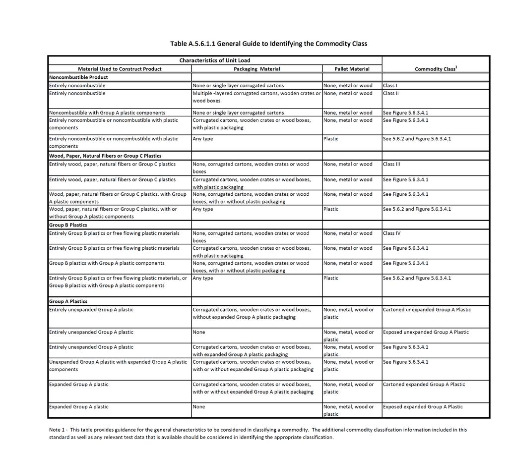
211
212 86 of /7/ :33 PM First Revision No. 292-NFPA [ Section No. A ] A The categories listed in , , and are based on unmodified plastic materials. The use of fire- or flame-retarding modifiers or the physical form of the material could change the classification. The addition of fire retardants to plastic should not be relied upon as the sole basis for a reduction in classification given the unknown performance of the fire retardant under a storage scenario. It is expected that full-scale or commodity classification type testing would be necessary to justify any such reduction in classification. No reduction in classification should be given for plastics simply because they contain a fire retardant. Plastic materials not specifically classified in should be protected as Group A plastics unless full-scale or commodity classification type testing demonstrates otherwise. It is not possible to classify full-scale fire performance of plastics by looking solely at heat of combustion. Plastic materials should not be categorized into a Group (A, B, or C) based upon comparing heat of combustion with values for plastics already classified in NFPA 13. Submitter Information Verification Submitter Full Name: Matthew Klaus Organization: National Fire Protection Assoc Street Address: City: State: Zip: Submittal Date: Tue Sep 17 17:38:54 EDT 2013 Committee Statement Committee Statement: Response Message: New annex material has been added to address the use of fire retardants as a means for reducing commodities. It is not the intent of the standard to permit derating of commodities based on the use of these products unless testing can validate the revised classification.
213 87 of /7/ :33 PM First Revision No. 67-NFPA [ New Section after A ] A Sprinklers should be permitted to be reinstalled when the sprinkler being removed from the system remains attached to the original fitting or welded outlet, provided care has been taken to ensure the sprinkler has not been damaged. Flexible hose connections are considered a fitting. In new installations, where sprinklers are installed on pendent drop nipples or sidewall sprinklers prior to final cut-back, protective caps and/or straps should remain in place until after the drop nipple has been cut to fit to the final ceiling elevation. Submitter Information Verification Submitter Full Name: [ Not Specified ] Organization: [ Not Specified ] Street Address: City: State: Zip: Submittal Date: Tue Aug 20 17:47:11 EDT 2013 Committee Statement Committee Statement: The concern of mechanical damage associated with removing sprinklers is applying torque on the sprinkler itself. Sprinklers that are removed by applying torque on a fitting can be reused. Special requirements addressing dry sprinklers have been added. Response Message: Public Input No. 477-NFPA [New Section after A.6.1.1]
214 88 of /7/ :33 PM First Revision No. 68-NFPA [ Section No. A ]
215 89 of /7/ :33 PM A.6.1.1
216 90 of /7/ :33 PM Included among items requiring listing are sprinklers, some pipe and some fittings, hangers, alarm devices, valves controlling flow of water to sprinklers, valve tamper supervisory switches, and electrically operated solenoid valves, and gauges. Products are typically investigated in accordance with published standards. Examples of standards used to investigate several products installed in sprinkler systems are referenced in Table A This table does not include a comprehensive list of all product standards used to investigate products installed in sprinkler systems. Table A Examples of Standards for Sprinkler System Products Category Sprinklers Valves Hangers Fittings Pressure Gages Standard ANSI/UL 199, Automatic Sprinklers for Fire Protection Service FM 2000, Automatic Control Mode Sprinklers for Fire Protection ANSI/UL 1626, Residential Sprinklers for Fire Protection Service FM 2030, Residential Automatic Sprinklers ANSI/UL 1767, Early-Suppression Fast-Response Sprinklers FM 2008, Suppression Mode ESFR Automatic Sprinklers FM 1632, Telescoping Sprinkler Assemblies for Use in Fire Protection Systems for Anechoic Chambers ANSI/UL 193, Alarm Valves for Fire Protection Service FM 1041, Alarm Check Valves ANSI/UL 260, Dry Pipe and Deluge Valves for Fire Protection Service FM 1021, Dry Pipe Valves FM 1020, Automatic Water Control Valves UL 262, Gate Valves for Fire Protection Service FM 1120, 1130, Fire Service Water Control Valves (OS & Y and NRS Type Gate Valves) ANSI/UL 312, Check Valves for Fire Protection Service FM 1210, Swing Check Valves UL 1091, Butterfly Valves for Fire Protection Service FM 1112, Indicating Valves (Butterfly or Ball Type) ANSI/UL 1468, Direct Acting Pressure Reducing and Pressure Restricting Valves ANSI/UL 1739, Pilot-Operated Pressure-Control Valves for Fire Protection Service FM 1362, Pressure Reducing Valves FM 1011/1012/1013, Deluge and Preaction Sprinkler Systems FM 1031, Quick Opening Devices (Accelerators and Exhausters) for Dry Pipe Valves FM 1042, Waterflow Alarm Indicators (Vane Type) FM 1045, Waterflow Detector Check Valves FM 1140, Quick Opening Valves 1 4 Inch Through 2 Inch Nominal Size ANSI/UL 203, Pipe Hanger Equipment for Fire Protection Service FM 1951, 1952, 1953, Pipe Hanger Components for Automatic Sprinkler Systems FM 1950, Seismic Sway Brace Components for Automatic Sprinkler Systems ANSI/UL 213, Rubber Gasketed Fittings for Fire Protection Service FM 1920, Pipe Couplings and Fittings for Fire Protection Systems UL 1474, Adjustable Drop Nipples for Sprinkler Systems FM 1631, Adjustable and Fixed Sprinkler Fittings 1 2 Inch through 1 Inch Nominal Size ANSI/UL 2443, Flexible Sprinkler Hose with Fittings for Fire Protection Service FM 1637, Flexible Sprinkler Hose with Fittings UL 393, Indicating Pressure Gauges for Fire Protection Service FM 2311, Pressure Gauges for Fire Protection Systems
217 91 of /7/ :33 PM Category Standard Submitter Information Verification Submitter Full Name: [ Not Specified ] Organization: [ Not Specified ] Street Address: City: State: Zip: Submittal Date: Tue Aug 20 17:55:50 EDT 2013 Committee Statement Committee Statement: Response Message: Guages are no longer required to be Listed. The reference to such should be removed. The term "valve tamper" was updated for consistency with the remainder of the task group. Public Input No. 338-NFPA [Section No. A.6.1.1]
218 92 of /7/ :33 PM First Revision No. 69-NFPA [ Section No. A ] A Extending the underground pipe such as ductile iron, C-900 PVC, and other pipe permitted by Chapter 10, into a building provides working room to transition to the appropriate aboveground piping. Environmental conditions should be considered as outlined in Submitter Information Verification Submitter Full Name: [ Not Specified ] Organization: [ Not Specified ] Street Address: City: State: Zip: Submittal Date: Tue Aug 20 18:02:56 EDT 2013 Committee Statement Committee Statement: During the previous revision cycle, the intent of Proposal and Comment was to clarify that it was acceptable to bring underground pipe into the building to specifically allow the transition above the floor, without having to make any special provisions. This clarification was lost however, when the TC amended the text that was offered, to address all piping and added the reference to These changes provide the clarification as it was originally intended. Additional language was provided to include additional piping materials permitted by ch 10. Response Message: Public Input No. 302-NFPA [Section No. A ]
219 93 of /7/ :33 PM First Revision No. 272-NFPA [ Sections A.6.3.7, A , A ] A CPVC is a plastic material, and consideration is necessary when other materials or chemicals come in contact with CPVC that can cause degradation of perfomance performance of the pipe due to interaction of materials. Other construction materials include but are not limited to materials used in fabrication of the sprinkler system, additives to water supplies, cable, and wiring, and certain insecticides and fungicides. Compliance with combined with following the manufacturer s guidance on installation and compatible materials will help prevent premature performance degradation of CPVC non-metallic piping. Excessive mechanical Mechanical stress caused by hanging methods or excessive bending on CPVC non-metallic piping beyond the manufacturers recommended limitations can cause stress failure over time and should be avoided. A When fabricating steel pipe for a combination (CPVC steel) system, the cutting oil and lubricants can cause performance degradation of the CPVC piping. Cutting oils and lubricants found to be compatible are available and should be used. A Other construction materials include but are not limited to materials used in fabrication of the sprinkler system, additives to water supplies, cable and wiring, and certain insecticides and fungicides. Submitter Information Verification Submitter Full Name: [ Not Specified ] Organization: [ Not Specified ] Street Address: City: State: Zip: Submittal Date: Tue Aug 27 12:48:30 EDT 2013 Committee Statement Committee Statement: CPVC is a plastic material and compatibility consideration is necessary when other materials or chemicals come in contact with CPVC that can cause degradation of performance of the pipe due to interaction of materials. The revised section and associated annex text have been reorganized for consistency with the language proposed for NFPA 13R. Test methods to determine material compatibility for certain products are being developed as part of a project to develop a new ANSI standard for this application. Therefore, using the compatibility information that is available at the time of system design is more meaningful. Response Message: Public Input No. 246-NFPA [Section No. A.6.3.7]
220 94 of /7/ :33 PM First Revision No. 273-NFPA [ Sections A , A ] A CPVC is a plastic material and consideration is necessary when other materials or chemicals come in contact with CPVC that can cause degradation of perfomance performance of the fitting due to interaction of materials. Compliance with combined with following manufacturer s guidance on installation and compatible materials will help prevent premature performance degradation of CPVC non-metallic fittings. Excessive mechanical Mechanical stress caused by hanging methods or excessive bending on CPVC non-metallic piping beyond the manufacturer's recommended limitations can cause stress failure over time and should be avoided. A When fabricating steel pipe for a combination (CPVC steel) system using non-metallic and steel pipe, the cutting oil and lubricants can cause performance degradation of the CPVC non-metallic fitting. Compatible cutting oils and lubricants are available and should be used. Submitter Information Verification Submitter Full Name: [ Not Specified ] Organization: [ Not Specified ] Street Address: City: State: Zip: Submittal Date: Tue Aug 27 12:58:52 EDT 2013 Committee Statement Committee Statement: Response Message: CPVC is a plastic material and compatibility consideration is necessary when other materials or chemicals come in contact with CPVC that can cause degradation of performance of the pipe due to interaction of materials. The revised section and associated annex text have been reorganized for consistency with the language proposed for NFPA 13R. Test methods to determine material compatibility for certain products are being developed as part of a project to develop a new ANSI standard for this application. Therefore, using the compatibility information that is available at the time of system design is more meaningful.
221 95 of /7/ :33 PM First Revision No. 71-NFPA [ Section No. A.6.6 ] A.6.6 See Section 9.1 for information pertaining to the type of hangers and hanger components acceptable for use on a sprinkler system. Submitter Information Verification Submitter Full Name: [ Not Specified ] Organization: [ Not Specified ] Street Address: City: State: Zip: Submittal Date: Tue Aug 20 18:07:39 EDT 2013 Committee Statement Committee Statement: Section 6.6 was deleted, therefore the annex needs to be removed as well. Response Message:
222 96 of /7/ :33 PM First Revision No. 70-NFPA [ Section No. A.6.10 ]
223 97 of /7/ :33 PM A.6.9
224 98 of /7/ :33 PM Table A.6.9 is a summary of the requirements for signs in NFPA 13. Table A.6.9 Sprinkler System Signage Summary Section Sign Location Sign Information/Requirements Control valves Identification sign Drain valves Test connection valves Sign must be made of weatherproof metal or rigid plastic and attached with corrosion-resistant wire or chain and Antifreeze system main valve Indicate the following: Circulating closed loop systems Antifreeze manufacturer Antifreeze type Antifreeze concentration All valves controlling sprinklers Sign worded as follows: Control valves Indicate valve function This valve controls fire protection equipment. Do not close until after fire has been extinguished. Use auxiliary valves when necessary to shut off supply to auxiliary equipment. Caution: Automatic alarm may be sounded if this valve is closed. Indicate system being controlled Dry valve Number of low point drains Preaction valve Fire department connections not serving the whole building All fire department connections Location of each drain Indicate portion of the building served by the fire department connection Indicate systems served by the fire department connection Indicate system pressure demand (for systems requiring more than 150 psi) Letters must be 1 in. in height Alarm valve Indicate the following: Dry pipe valve Location of the design area or areas Preaction valve Discharge densities over the design area or areas Deluge valve Required flow and residual pressure demand at the base of the riser Occupancy classification or commodity classification and maximum permitted storage height and configuration Hose stream allowance The installing contractor System control riser Indicate the following: Sign must be made of weatherproof metal or rigid plastic and attached with corrosion-resistant wire or chain Antifreeze loops Name and location of the facility Auxiliary systems Occupancy and commodity classification Control valves Flow test data
225 99 of /7/ :33 PM Section Sign Location Sign Information/Requirements Submitter Information Verification Submitter Full Name: [ Not Specified ] Organization: [ Not Specified ] Street Address: City: State: Zip: Submittal Date: Tue Aug 20 18:06:43 EDT 2013 Committee Statement Committee Statement: Response Message: corrected typo. Only 24.5 and 24.6 were modified but the program underlined all the existing text. Public Input No. 88-NFPA [Section No. A.6.10]
226 00 of /7/ :33 PM First Revision No. 285-NFPA [ Sections A.7.6.1, A.7.6.2, A ] A The definition of an antifreeze system states that water will discharge after the antifreeze leaves the pipes. Systems that are all antifreeze, including tanks of antifreeze solution that will not discharge plain water, are not true antifreeze systems. Such systems should not be used without consideration to issues such as the combustibility of the antifreeze solution and the friction loss in the piping during cold conditions. Any listing associated with an antifreeze sprinkler system should address the inability for the specific antifreeze solution tested to ignite when discharged from specific sprinklers.
227 01 of /7/ :33 PM A.7.6.2
228 02 of /7/ :33 PM Listed nonmetallic sprinkler pipe and fittings should be protected from freezing with compatible listed solutions only. In addition, due to antifreeze solution limitations, other methods of freeze protection such as electric heat tracing or insulated coverings, which are approved for use on nonmetallic piping, can be used to protect nonmetallic pipes from freezing. The following is a list of research reports that have been issued by the Fire Protection Research Foundation (FPRF) related to the use of antifreeze in sprinkler systems: (1) Antifreeze Systems in Home Fire Sprinkler Systems Literature Review and Research Plan, Fire Protection Research Foundation, June 2010 (2) Antifreeze Systems in Home Fire Sprinkler Systems Phase II Final Report, Fire Protection Research Foundation, December 2010 (3) Antifreeze Solutions Supplied through Spray Sprinklers Interim Report, Fire Protection Research Foundation, February 2012 Table A provides a summarized overview of the testing. Table A FPRF Antifreeze Testing Summary Topic Scope of sprinklers tested Antifreeze solution concentration Sprinkler inlet pressure Information The following sprinklers were used during the residential sprinkler research program described in the report dated December 2010: (1) Residential pendent style having nominal K-factors of 3.1, 4.9, and 7.4 gpm/psi 1/2 (2) Residential concealed pendent style having a nominal K-factor of 4.9 gpm/psi 1/2 (3) Residential sidewall style having nominal K-factors of 4.2 and 5.5 gpm/psi 1/2 The following sprinklers were used during the spray sprinkler research program described in the report dated February 2012: (1) Residential pendent style having a nominal K-factor of 3.1 gpm/psi 1/2 (2) Standard spray pendent style having nominal K-factors of 2.8, 4.2, 5.6, and 8.0 gpm/psi 1/2 (3) Standard spray concealed pendent style having a nominal K-factor of 5.6 gpm/psi 1/2 (4) Standard spray upright style having a nominal K-factor of 5.6 gpm/psi 1/2 (5) Standard spray extended coverage pendent style having a nominal K-factor of 5.6 gpm/psi 1/2 <50% glycerine and <40% propylene glycol antifreeze solutions: Solutions were not tested. 50% glycerine and 40% propylene glycol antifreeze solutions: Large-scale ignition of the sprinkler spray did not occur in tests with sprinkler discharge onto a fire having a nominal heat release rate (HRR) of 1.4 megawatts (MW). Large-scale ignition of sprinkler spray occurred in multiple tests with sprinkler discharge onto a fire having a nominal HRR of 3.0 MW. 55% glycerine and 45% propylene glycol antifreeze solutions: Large-scale ignition of the sprinkler spray occurred in tests with sprinkler discharge onto a fire having a nominal HRR of 1.4 MW. > 55% glycerine and > 45% propylene glycol antifreeze solutions: Large-scale ignition of the sprinkler spray occurred in tests with sprinkler discharge onto a fire having an HRR of less than 500 kw. 70% Glycerine and 60% propylene glycol antifreeze solutions: Maximum antifreeze solution concentrations tested. Large-scale ignition of the sprinkler discharge spray was not observed when the sprinkler inlet pressure was 50 psi or less for tests using 50% glycerine or 40% propylene glycol.
229 03 of /7/ :33 PM Topic Information A Where existing antifreeze systems have been analyzed and approved to remain in service, antifreeze solutions should be limited to premixed antifreeze solutions of glycerine (chemically pure or United States Pharmacopoeia 96.5 percent) at a maximum concentration of 48 percent by volume, or propylene glycol at a maximum concentration of 38 percent by volume. The use of antifreeze solutions in all new sprinkler systems should be restricted to listed antifreeze solutions only. Where existing antifreeze systems are in service, the solution concentration should be limited to those noted in A , and the system requires an analysis and approval of the AHJ to remain in service. Submitter Information Verification Submitter Full Name: [ Not Specified ] Organization: [ Not Specified ] Street Address: City: State: Zip: Submittal Date: Thu Sep 05 18:25:02 EDT 2013 Committee Statement Committee Note: This Proposal originates from Tentative Interim Amendment (TIA 1066) issued by the Statement: Standards Council on August 9, The information provided in the Fire Protection Research Foundation report Antifreeze Solutions Supplied through Spray Sprinklers: Interim Report illustrates that under certain conditions (pressure, fire size, k-factor, ceiling height, deflector design etc) a 50% glycerine solution is capable of igniting and causing a dramatic increase in heat release rate. As noted in the FPRF report, these results highlight the complicated interaction between sprinkler spray and the ignition source. As a result of this additional testing, there are more questions that need to be answered, and the testing shows that concentrations of anti-freeze that previous testing indicated were acceptable and would not support combustion actually do with a stronger ignition source. In addition, sprinklers with larger orifices that require lower pressure than typical residential sprinklers and potentially a lager droplet distribution also ignited. It is clear that further testing is need to fully understand under what conditions an anti-freeze solutions are safe, anti-freeze solutions can not be allowed in sprinkler systems. This TIA calls for the use of Listed Antifreeze Solutions. Using listed antifreeze solutions will ensure that the solution discharged from a sprinkler system will not ignite or cause a dramatic increase in heat release rate of a fire. The process for developing listed products will also allow for a continued improvement in fire and life safety in environments meeting the NFPA Codes and Standards. This TIA also calls for the continued acceptance of currently listed ESFR Antifreeze Systems. The listing process has already shown that, in some cases, it is possible to use current antifreeze solutions to provide the level of protection prescribed by NFPA 13. For this reason, it is proposed to allow the continued use of propylene-glycol solutions in systems and in protection scenarios that have been thoroughly tested to demonstrate such results. There are ESFR systems currently available that have been specifically tested and listed with a specific model of sprinkler and solution delivery method that provide an appropriate level of protection as to be considered Early Suppression. Emergency Nature: The latest testing from The Fire Protection Research Foundation titled Antifreeze Solutions Supplied through Spray Sprinklers Interim Report (dated February 2012) shows that anti-freeze concentrations currently allowed in new NFPA 13 sprinkler systems may support combustion and increase the size of the fire. This is a safety issue that requires changes in the standard. The following are two items which make this TIA of emergency nature. Only one is required for substantiation of an emergency nature. (d) The proposed TIA intends to offer to the public a benefit that would lessen a recognized (known) hazard or ameliorate a continuing dangerous condition or situation During the latest revision cycle the committee evaluated the test data that was present at the time of the cycle. The committee could not anticipate that additional data would change our justifications during the process. The new data demonstrates that variables utilized in the development of the 2013 edition may lead to changes in the fire involvement. Propylene glycol and glycerin antifreeze solutions discharged from sprinklers have the potential to ignite under certain conditions. Research testing has indicated that several variables may influence the potential for large scale
230 04 of /7/ :33 PM ignition of the antifreeze solution discharged from a sprinkler. These variables include, but are not limited to, the concentration of antifreeze solution, sprinkler discharge characteristics, inlet pressure at the sprinkler, location of fire relative to the sprinkler, and size of fire at the time of sprinkler discharge. (f ) The proposed TIA intends to correct a circumstance in which the revised document has resulted in an adverse impact on a product or method that was inadvertently overlooked in the total revision process, or was without adequate technical (safety) justification for the action. Antifreeze solutions have been subject to recent testing and the new data shows that the installations found within the standard do not account for the complete safety of the occupant. The data appears to provide additional questions and challenges the parameters of installation found in the standard. The use of propylene glycol and glycerin antifreeze solutions should only be considered when other sprinkler system design alternatives are not available or practical. If these solutions are used, all relevant data and information should be carefully reviewed and considered in the sprinkler system. Response Message: Public Input No. 35-NFPA [Sections A.7.6.1, A.7.6.2, A ]
231 05 of /7/ :33 PM First Revision No. 129-NFPA [ Section No. A ] A This standard contemplates full sprinkler protection for all areas including walk-in coolers, freezers, bank vaults, and similar areas. Other NFPA standards that mandate sprinkler installation might not require sprinklers in certain areas. Based upon experience and testing, sprinklers have been found to be effective and necessary at heights in excess of 50 ft (15.2 m). For a building to meet the intended level of protection afforded by NFPA 13, sprinklers must not be omitted from such high ceiling spaces. The requirements of this standard should be used insofar as they are applicable. The authority having jurisdiction should be consulted in each case. A building is considered sprinklered throughout when protected in accordance with the requirements of this standard. In situations such as computer rooms where a gas system is installed, the sprinkler protection should not be eliminated. Many gas systems do not have the same duration requirements of a fire sprinkler system, and if the fire is not extinguished with the initial discharge, the fire could grow large enough to overpower the sprinkler system. Submitter Information Verification Submitter Full Name: [ Not Specified ] Organization: [ Not Specified ] Street Address: City: State: Zip: Submittal Date: Wed Aug 21 18:01:42 EDT 2013 Committee Statement Committee Statement: The importance of protecting all area is the purpose of this annex section. Some building codes indicate that sprinklers can be eliminated from rooms with gas systems. If the committee is serious about their desire to sprinkler all areas, then this reference to gas systems and computer rooms is needed as this is the most common situation where sprinklers are omitted. Response Message: Public Input No. 146-NFPA [Section No. A.8.1.1]
232 06 of /7/ :33 PM First Revision No. 83-NFPA [ New Section after A ] A (1) Areas used for hot yoga facilities, steam rooms, saunas, indoor areas containing hot tubs, and similar heated areas should be evaluated to determine the potential maximum ambient temperature before selection of sprinkler temperature rating to be installed in the space. Submitter Information Verification Submitter Full Name: [ Not Specified ] Organization: [ Not Specified ] Street Address: City: State: Zip: Submittal Date: Wed Aug 21 11:17:44 EDT 2013 Committee Statement Committee Statement: Response Message: The proposed languages provides a list of areas where consideration is needed to ensure sprinklers of the appropriate temperature ratings are installed in hot room spaces. Public Input No. 203-NFPA [Section No ]
![07 of 474 11/7/2013 12:33 PM First Revision No. 130-NFPA 13-2013 [ Section No. A.8.5.5.1 ] A.8.5.5.1 See Figure A.8.5.5.1. for a representation of a typical spray sprinkler pattern.](/docs-images/74/69678083/images/233-0.jpg "NFPA 13 strives to minimize the effect of obstructions through the use of specific criteria in 8.5.5, 8.6.5, 8.7.5, 8.8.5, 8.9.5, 8.10.6, 8.10.7, 8.11.5, and 8.12.5. The obstruction criteria for storage sprinklers in 8.")
233 07 of /7/ :33 PM First Revision No. 130-NFPA [ Section No. A ] A See Figure A for a representation of a typical spray sprinkler pattern. NFPA 13 strives to minimize the effect of obstructions through the use of specific criteria in 8.5.5, 8.6.5, 8.7.5, 8.8.5, 8.9.5, , , , and The obstruction criteria for storage sprinklers in and is the most stringent. For other types of sprinklers, dry spaces caused be obstructions such as columns and wall configurations will occur and can comply with the standard. The general rules known as the "three-times rule" and the "four-times rule" define dry areas or "shadow areas" that are acceptable behind obstructions like columns and walls. Tests have shown that the larger the column, the larger the dry area behind the column will be and the longer it will take for sprinklers on the other side of the column to react to the fire behind the column. In a very large compartment, the delay could become unacceptable. The delay in sprinkler response can be minimized with smaller columns, with smaller compartments, or by putting sprinklers on the other side of the column. Where offset walls create shadowed areas, the sprinkler does not appear to be significantly delayed in activation. Tests have shown that once the sprinkler activates, water will not cover all areas behind the obstructions. Figure A Obstructions to Sprinkler Discharge Pattern Development for Standard Upright or Pendent Spray Sprinklers. Submitter Information Verification Submitter Full Name: [ Not Specified ] Organization: [ Not Specified ] Street Address: City: State: Zip: Submittal Date: Wed Aug 21 18:08:08 EDT 2013 Committee Statement Committee Statement: The revised text provides direction on the impact of obstructions and the creation of shadow areas.
234 08 of /7/ :33 PM Response Message: Public Input No. 410-NFPA [Section No. A ]
235 09 of /7/ :33 PM First Revision No. 131-NFPA [ Section No. A (5) ] A (5) For concrete joists spaced less than 3 ft (0.91 m) on center, the rules for obstructed construction shown in apply. For concrete tee construction with stems spaced less than 7 ft 6 in. (2.3 m) but more than 3 ft (0.91 m) on center, the sprinkler deflector can be located at or above a horizontal plane 1 in. (25.4 mm) below the bottom of the stems of the tees. This includes sprinklers located between the stems. [See Figure A (5).] Figure A (5) Typical Concrete Joist Construction. Supplemental Information File Name FR_131.docx Description Submitter Information Verification Submitter Full Name: [ Not Specified ] Organization: [ Not Specified ] Street Address: City: State: Zip: Submittal Date: Wed Aug 21 18:18:49 EDT 2013 Committee Statement Committee Statement: This figure does not supply a true graphic representation of a concrete tee. Response Message: Public Input No. 533-NFPA [Section No. A (5)]
236
237 10 of /7/ :33 PM First Revision No. 172-NFPA [ Section No. A ] A The intent of (3) is to apply to soffits that are located within the 18 in. (457 mm) plane from the sprinkler deflector. A soffit or other obstruction (i.e., shelf) located against a wall that is located entirely below the 18 in. (457 mm) plane from the sprinkler deflector should be in accordance with (See Figure A ) Figure A Soffit/Obstruction Against Wall Greater Than 18 in. (457 mm) Below Deflector. Submitter Information Verification Submitter Full Name: [ Not Specified ] Organization: [ Not Specified ] Street Address: City: State:
238 11 of /7/ :33 PM Zip: Submittal Date: Thu Aug 22 18:33:01 EDT 2013 Committee Statement Committee Statement: The annex cannot include requirements. Response Message:
239 12 of /7/ :33 PM First Revision No. 171-NFPA [ Section No. A ] A The intent of (3) is to apply to soffits that are located within the 18 in. (457 mm) plane from the sprinkler deflector. A soffit or other obstruction (i.e., shelf) located against a wall that is located entirely below the 18 in. (457 mm) plane from the sprinkler deflector should be in accordance with (See Figure A ) Figure A Soffit/Obstruction Against Wall Greater Than 18 in. (457 mm) Below Deflector. Submitter Information Verification Submitter Full Name: [ Not Specified ] Organization: [ Not Specified ] Street Address: City: State: Zip:
240 13 of /7/ :33 PM Submittal Date: Thu Aug 22 18:29:51 EDT 2013 Committee Statement Committee Statement: This revision correlates with A (c). Response Message:
241 14 of /7/ :33 PM First Revision No. 161-NFPA [ New Section after A (3) ] A The obstruction rules of have been primarily written to address horizontal obstructions like ducts and lights where the sprinkler needs to spray under the obstruction or get water both over and under the obstruction. For vertical obstruction situations like columns where the water needs to get to two sides of the obstruction, the guidance in to keep the sprinklers at least 12 in. (305 mm) from obstructions up to 12 in. (305 mm) wide and to keep the sprinkler 24 in. (610 mm) from obstructions over 12 in. (305 mm) to 24 in. (610 mm) wide can be used. For obstructions like columns that are more than 24 in. (610 mm) wide, a sprinkler should be placed on the opposite side of the obstruction while following the minimum and maximum spacing requirements of Submitter Information Verification Submitter Full Name: [ Not Specified ] Organization: [ Not Specified ] Street Address: City: State: Zip: Submittal Date: Thu Aug 22 15:33:43 EDT 2013 Committee Statement Committee Statement: Guidance is needed to deal with vertical obstructions like columns. Without fire testing or ADD testing, we have been reluctant to actually propose specific requirements for the body of the standard. But some mention of the situation deserves to be in the annex. Response Message: Public Input No. 391-NFPA [New Section after A (3)]
242 15 of /7/ :33 PM First Revision No. 162-NFPA [ New Section after A ] A For example, a 1 in. (25 mm) diameter conduit would need to be 3 in. (75 mm) from the nearest pipe or conduit to be considered as an individual obstruction. Otherwise, the pipes and/or conduits would be considered as a group when applying the obstruction criteria in Submitter Information Verification Submitter Full Name: [ Not Specified ] Organization: [ Not Specified ] Street Address: City: State: Zip: Submittal Date: Thu Aug 22 15:34:11 EDT 2013 Committee Statement Committee Statement: Response Message: This new annex section is related to the FR for a new Section This is the example for the what is required by Public Input No. 451-NFPA [New Section after A ]
243 16 of /7/ :33 PM First Revision No. 143-NFPA [ New Section after A ] A Utilities and other building services can be located within the concealed spaces. Submitter Information Verification Submitter Full Name: [ Not Specified ] Organization: [ Not Specified ] Street Address: City: State: Zip: Submittal Date: Thu Aug 22 11:35:30 EDT 2013 Committee Statement Committee Statement: Response Message: There are many variables that need to be taken into account when determing the density for any specific scenario. The document gives guidance for making this determination. Public Input No. 513-NFPA [New Section after ]
244 17 of /7/ :33 PM First Revision No. 163-NFPA [ Section No. A ] A Being eposed to the outside atmosphere is not necessarily a corrosive environment. Types of locations where corrosive conditions can exist include bleacheries, dye houses, metal plating processes, animal pens, and certain chemical plants. If corrosive conditions are not of great intensity and humidity is not abnormally high, good results can be obtained by a protective coating of red lead and varnish or by using a good grade of commercial acid-resisting paint. The paint manufacturer's instructions should be followed in the preparation of the surface and in the method of application. Where moisture conditions are severe but corrosive conditions are not of great intensity, copper tube or galvanized steel pipe, fittings, and hangers might be suitable. The exposed threads of steel pipe should be painted. In instances where the piping is not accessible and where the exposure to corrosive fumes is severe, either a protective coating of high quality can be employed or some form of corrosion-resistant material used. Submitter Information Verification Submitter Full Name: [ Not Specified ] Organization: [ Not Specified ] Street Address: City: State: Zip: Submittal Date: Thu Aug 22 15:40:58 EDT 2013 Committee Statement Committee Statement: Many AHJ's consder piping installed with exposure to the outside atmosphere to be installed in a corrosive environment. Inland installations should not be considered corrosive environments. Red lead and varnished are no longer used, so this was struck from the annex section. Response Message: Public Input No. 134-NFPA [Section No. A ]
245 18 of /7/ :33 PM First Revision No. 280-NFPA [ Section No. A ] A A manual or automatic air venting valve can be a reasonable approach on wet pipe sprinkler systems to reduce corrosion activity. The purpose of the air venting valve is to exhaust as much trapped air as possible from a single location every time the system is filled. The objective of venting is to reduce the amount of oxygen trapped in the system that will fuel corrosion and microbial activity. It is neither the intent nor practical to exhaust all trapped air from a single location on a wet pipe sprinkler system; however, more than one vent can be used on a system at the designer's discretion. Interconnection of branch line piping for venting purposes is not necessary. An inspector's test valve can serve this purpose. The air venting valve should be located where it will be most effective. System piping layout will guide the designer in choosing an effective location for venting. In order to effectively accomplish venting, it is necessary to choose a location where the greatest volume of trapped air is vented during the first fill and each subsequent drain and fill event. The vent connection to the system should be located off the top of horizontal piping at a high point in the system; however, the vent connection can also be effectively located off the side of a riser or riser nipple at a high point in the system. Manual air venting valves should be accessible. The manual air venting valve should be located at an accessible point and preferably not over 7 ft (2 m) above the floor. Automatic air valves are not required to comply with the accessibility requirement of manual air venting valves; however, it is recommended the designer locate automatic air vents over areas without ceilings, above a lay-in ceiling, or above an access panel. Each wet pipe sprinkler system should be vented every time the system is filled. Submitter Information Verification Submitter Full Name: [ Not Specified ] Organization: [ Not Specified ] Street Address: City: State: Zip: Submittal Date: Thu Sep 05 18:13:16 EDT 2013 Committee Statement Committee Statement: Annex section relocated to be linked to new requirement for system venting. Response Message:
246 19 of /7/ :33 PM First Revision No. 289-NFPA [ Section No. A ] A The purpose of this alarm test connection is to make sure the alarm device is sensitive enough to determine the flow from a single sprinkler and sound an alarm. The purpose of this test connection is not to ensure that water will flow through the entire system. When this test connection is installed on the upper story, and at the end of the most remote branch line, the user is able to tell that there is water flowing in one path through the system, but there is no assurance that water will flow to other branch lines. Putting the test connection at the most remote portion of the system causes the introduction of fresh oxygen into a large part of the system each time the alarm is tested and increases the corrosion that will occur in the piping. The discharge should be at a point where it can be readily observed. In locations where it is not practical to terminate the test connection outside the building, the test connection is permitted to terminate into a drain capable of accepting full flow under system pressure. In this event, the test connection should be made using an approved sight test connection containing a smooth bore corrosion-resistant orifice giving a flow equivalent to one sprinkler simulating the least flow from an individual sprinkler in the system. [See Figure A (a) and Figure A (b).] The test valve should be located at an accessible point and preferably not over 7 ft (2.1 m) above the floor. The control valve on the test connection should be located at a point not exposed to freezing. Figure A (a) System Test Connection on Wet Pipe System. Figure A (b) Floor Control Valve. System Test Connection on Wet Pipe System. Submitter Information Verification Submitter Full Name: [ Not Specified ]
247 20 of /7/ :33 PM Organization: [ Not Specified ] Street Address: City: State: Zip: Submittal Date: Thu Sep 05 19:28:36 EDT 2013 Committee Statement Committee Statement: Response Message: Section is on wet pipe system test connections. Changed Figure title to reflect the subject matter of this section. Public Input No. 573-NFPA [Section No. A ]
248 21 of /7/ :33 PM First Revision No. 38-NFPA [ New Section after A ] A Other standards equivalent to ASTM A307 grades A or B include SAE J429 Grades 1 or 2. Both fasteners are fabricated from low or medium carbon steel, and requirements have a minimum tensile strength of 60 ksi. Submitter Information Verification Submitter Full Name: [ Not Specified ] Organization: [ Not Specified ] Street Address: City: State: Zip: Submittal Date: Tue Aug 13 18:22:14 EDT 2013 Committee Statement Committee Statement: Response Message: The annex reference provides examples of equivalent materials equivalent to ASTM A307 fasteners.
249 22 of /7/ :33 PM First Revision No. 43-NFPA [ Section No. A ] A Examples include headers and horizontal runs of pipe that need support from the floor. Where applicable, the design of pipe stands should consider additional loading from other sources. Environmental impacts, including water accumulation at the base, corrosion, and wind should also be taken into account as appropriate. The performance of piping support systems should allow for expansion and contraction due to temperature change, expansion due to internal water pressure (thrust), restrained and/or unrestrained joints or pipe runs, heavy point loads (e.g., valves), and pipe deflection (span/support spacing). Manufacturer s installation instructions and engineering design guides should be consulted when available. Examples of common applications include headers and horizontal runs of pipe that need support from the floor. Submitter Information Verification Submitter Full Name: [ Not Specified ] Organization: [ Not Specified ] Street Address: City: State: Zip: Submittal Date: Tue Aug 13 21:05:47 EDT 2013 Committee Statement Committee Statement: Response Message: The Committee has agreed that pipe stand requirements should be specified as part of the other support requirements for water-based fire protection systems. The text for the first revision has been adapted from existing criteria in NFPA 15 as well as efforts from a task group on this subject. The following concepts that were sought to be incorporated were: an alternate requirement for professional engineers, material options for the pipe stand, addressing the slenderness ratio of pipe in a column, addressing thrust from system filling or dry applications, addressing the use of pipe saddles, interior versus exterior applications, addressing pipe stands when in areas subject to seismic requirements. Other standards and model codes reference NFPA 13 for requirements on hanging, supporting and bracing water based fire protection equipment. The Committee and task group recognize that additional information will be needed at the second revision. Items anticipated include base plate information, looped piping, and figures for clearer explanations.
250 23 of /7/ :33 PM First Revision No. 31-NFPA [ Section No. A ] A Sprinkler systems are protected against earthquake damage by means of the following: (1) Stresses that would develop in the piping due to differential building movement are minimized through the use of flexible joints or clearances. (2) Bracing is used to keep the piping fairly rigid when supported from a building component expected to move as a unit, such as a ceiling. Areas known to have a potential for earthquakes have been identified in building code and insurance maps. Displacement due to story drift is addressed in through Piping in racks needs to be treated like other sprinkler piping and protected in accordance with the proper rules. Piping to which in-rack sprinklers are directly attached should be treated as branch line piping. Piping that connects branch lines in the racks should be treated as mains. The bracing, restraint, flexibility, and requirements for flexible couplings are the same in the rack structures as at the ceiling. Submitter Information Verification Submitter Full Name: [ Not Specified ] Organization: [ Not Specified ] Street Address: City: State: Zip: Submittal Date: Tue Aug 13 14:44:07 EDT 2013 Committee Statement Committee Statement: The standard needs some clarification on how to address piping in the racks. many people believe that they can ignore the protection rules because they are far from the building structure. They do not realize that the rack becomes the structure. This simple annex note should get them pointed in the right direction Response Message: Public Input No. 357-NFPA [Section No. A.9.3.1]
251 24 of /7/ :33 PM First Revision No. 16-NFPA [ New Section after A ] A Figure A is an example of piping supported by structure where there is no clearance required at the point of contact between the piping and structure. Figure A Pipe with Zero Clearance. Supplemental Information File Name clearance.jpg Description Submitter Information Verification Submitter Full Name: [ Not Specified ] Organization: [ Not Specified ] Street Address: City: State: Zip: Submittal Date: Mon Aug 12 15:38:17 EDT 2013 Committee Statement Committee Statement: Response Message: The intent of this section is to not require clearance at the point of clearance. The proposed figure illustrates this point. Public Input No. 554-NFPA [Section No ]
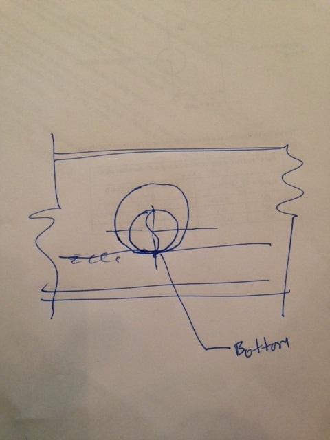
252
253 25 of /7/ :33 PM First Revision No. 32-NFPA [ Section No. A ]
254 26 of /7/ :33 PM A.9.3.5
 Seismic Bracing Calculation Form. Figure A.9.3.5(b) Sample Seismic Bracing Calculation Form.")
255 27 of /7/ :33 PM Figure A.9.3.5(a) and Figure A.9.3.5(b) are examples of forms used to aid in the preparation of bracing calculations. Figure A.9.3.5(a) Seismic Bracing Calculation Form. Figure A.9.3.5(b) Sample Seismic Bracing Calculation Form.

256 28 of /7/ :33 PM Supplemental Information File Name Figure_A.9.3.5_a_.G pdf Figure_A.9.3.5_b_.G pdf Description Submitter Information Verification Submitter Full Name: [ Not Specified ] Organization: [ Not Specified ] Street Address:
257 29 of /7/ :33 PM City: State: Zip: Submittal Date: Tue Aug 13 15:06:47 EDT 2013 Committee Statement Committee Statement: The Figures in the 2013 edition do not indicate what main size and pipe type is used when applying section and they don't have a place for the Structural Attachement Listed Load Rating and Adjusted Load Rating. Response Message: Public Input No. 482-NFPA [Section No. A.9.3.5]

258

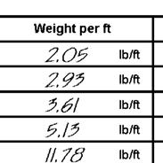
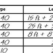
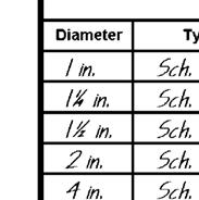

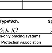
259
260 30 of /7/ :33 PM First Revision No. 33-NFPA [ Section No. A ]
261 31 of /7/ :33 PM A
262 32 of /7/ :33 PM Location of Sway Bracing. Two-way braces are either longitudinal or lateral, depending on their orientation with the axis of the piping. [See Figure A (a), Figure A (b), Figure A (c), and Figure A (d).] The simplest form of two-way brace is a piece of steel pipe or angle. Because the brace must act in both compression and tension, it is necessary to size the brace to prevent buckling. An important aspect of sway bracing is its location. In Building 1 of Figure A (a), the relatively heavy main will pull on the branch lines when shaking occurs. If the branch lines are held rigidly to the roof or floor above, the fittings can fracture due to the induced stresses. In selecting brace locations, one must consider both the design load on the brace, as well as the ability of the pipe to span between brace locations. Bracing should be on the main as indicated at Location B of Figure A (a). With shaking in the direction of the arrows, the light branch lines will be held at the fittings. Where necessary, a lateral brace or other restraint should be installed to prevent a branch line from striking against building components or equipment. A four-way brace is indicated at Location A of Figure A (a). This keeps the riser and main lined up and also prevents the main from shifting. In Building 1 of Figure A (a), the branch lines are flexible in a direction parallel to the main, regardless of building movement. The heavy main cannot shift under the roof or floor, and it also steadies the branch lines. While the main is braced, the flexible couplings on the riser allow the sprinkler system to move with the floor or roof above, relative to the floor below. Figure A (a) Typical Earthquake Protection for Sprinkler Main Piping. Figure A (b), Figure A (c), and Figure A (d) show typical locations of sway bracing. Figure A (b) Typical Location of Bracing on Mains on Tree System.
263 33 of /7/ :33 PM Figure A (c) Typical Location of Bracing on Mains on Gridded System. Figure A (d) Typical Location of Bracing on Mains on Looped System. For all threaded connections, sight holes or other means should be provided to permit indication that sufficient thread is engaged. To properly size and space braces, it is necessary to employ the following steps: (1) Determine the seismic coefficient, C, using the procedures in or This is p needed by the designer to verify that the piping can span between brace points. For the purposes of this example, assume that C = 0.5. p (2) Based on the distance of mains from the structural members that will support the braces, choose

264 34 of /7/ :33 PM brace shapes and sizes from Table (a), Table (b), and Table (c) such that the maximum slenderness ratios, l/r, do not exceed 300. The angle of the braces from the vertical should be at least 30 degrees and preferably 45 degrees or more. (3) Tentatively space lateral braces at 40 ft (12 m) maximum distances along mains, and tentatively space longitudinal braces at 80 ft (24 m) maximum distances along mains. Lateral braces should meet the piping at right angles, and longitudinal braces should be aligned with the piping. (4) Determine the total load tentatively applied to each brace in accordance with the examples shown in Figure A (e) and the following: (a) (b) (c) (d) For the loads on lateral braces on cross mains, add C times the weight of the branch to C p p times the weight of the portion of the cross main within the zone of influence of the brace. [See examples 1, 3, 6, and 7 in Figure A (e).] For the loads on longitudinal braces on cross mains, consider only C times the weight of the p cross mains and feed mains within the zone of influence. Branch lines need not be included. [See examples 2, 4, 5, 7, and 8 in Figure A (e).] For the four-way brace at the riser, add the longitudinal and lateral loads within the zone of influence of the brace [see examples 2, 3, and 5 in Figure A (e)]. For the four-way bracing at the top of the riser, C times the weight of the riser should be assigned to both the p lateral and longitudinal loads as they are separately considered. When a single brace has a combined load from both lateral and longitudinal forces (such as a lateral brace at the end of a main that turns 90 degrees), only the lateral should be considered for comparison with the load tables in (5) If the total expected loads are less than the maximums permitted in Table (a), Table (b), and Table (c) for the particular brace and orientation, and the maximum loads in the zone of influence of each lateral sway brace are less than the maximum values in Table (a) or Table (b), go on to step (6) A (6). If not, add additional braces to reduce the zones of influence of overloaded braces. (6) Check that fasteners connecting the braces to structural supporting members are adequate to support the expected loads on the braces in accordance with Figure If not, again add additional braces or additional means of support. Plates using multiple fasteners in seismic assemblies should follow the plate manufacturer guidelines regarding the applied loads. Use the information on weights of water-filled piping contained within Table A The factor of 1.15 is intended to approximate the additional weight of all the valves, fittings, and other devices attached to the system. Figure A (e) Examples of Load Distribution to Bracing. Table A Piping Weights for Determining Horizontal Load Nominal Dimensions Weight of Water-Filled Pipe in. mm lb/ft kg/m Schedule 40 Pipe
265 35 of /7/ :33 PM Nominal Dimensions Weight of Water-Filled Pipe in. mm lb/ft kg/m * Schedule 10 Pipe * Schedule 30. Submitter Information Verification Submitter Full Name: [ Not Specified ] Organization: [ Not Specified ] Street Address: City: State: Zip: Submittal Date: Tue Aug 13 15:42:10 EDT 2013 Committee Statement Committee Statement: Response Message: This revisions simply adds "or " to part (1) of the procedure. This is in keeping with the rules of NFPA 13 regarding the determination of Cp. Public Input No. 397-NFPA [Section No. A ]
266 36 of /7/ :33 PM First Revision No. 34-NFPA [ Section No. A ] A Where the C is 1.0 or greater, the calculation should be done for any length riser nipple. The loads in p this condition can rapidly exceed the yield strength. Where steel Schedule 10 and Schedule 40 pipe are used, the section modules modulus can be found in Table (b). Submitter Information Verification Submitter Full Name: [ Not Specified ] Organization: [ Not Specified ] Street Address: City: State: Zip: Submittal Date: Tue Aug 13 15:42:51 EDT 2013 Committee Statement Committee Statement: Typographic error to correct the term "modulus. A sentence clarifying that wherever CP is 1.0 or greater was added to correlate with the the 3 exceptions to performing the calculation that were added to Response Message: Public Input No. 428-NFPA [Section No. A ]
267 37 of /7/ :33 PM First Revision No. 35-NFPA [ New Section after A ] A Sway brace design and installation is critical to performance and requires attention to detail. Sway brace design parameters are dynamic and interdependent. Accordingly, seismic force is influenced by geography, brace location is impacted by system design, and brace geometry is relative to the building structure. To enhance system durability and performance, sway brace installation should show evidence of good craftsmanship in conformance to approved drawings, correctly assembled and mounted at proper angles on a plane that corresponds to the parallel and perpendicular axis of the system pipe. Submitter Information Verification Submitter Full Name: [ Not Specified ] Organization: [ Not Specified ] Street Address: City: State: Zip: Submittal Date: Tue Aug 13 15:48:38 EDT 2013 Committee Statement Committee Statement: AHJ s continue to request an appendix statement regarding sway brace installation Q.C. similar to the hanger installation statement at A.9.2. This section was relocated to A where it is more appropriate as it is a general discuss about sway bracing QC. Response Message: Public Input No. 553-NFPA [New Section after A ]
268 38 of /7/ :33 PM First Revision No. 174-NFPA [ Section No. A ] A Modern seismic codes require branch lines to be restrained, both to limit interaction of the pipe with other portions of the structure and to limit stresses in the pipes to permissible limits. The maximum spacing between restraints is dependent on the seismic coefficient, C p, as shown in Table (a). Table (a) has been limited to 2 in. (50 mm) lines and smaller, because branch lines in. (65 mm) or larger are required to be seismically braced. It is not the intent of this section to require restraint of piping associated with valve trim, water motor gong piping, air or nitrogen supply piping, or other piping that is not essential to the operation of the sprinkler system. Essential piping such as fire pump sensing lines and diesel fuel lines are some examples of small piping that should be restrained. Submitter Information Verification Submitter Full Name: [ Not Specified ] Organization: [ Not Specified ] Street Address: City: State: Zip: Submittal Date: Sat Aug 24 12:44:06 EDT 2013 Committee Statement Committee Statement: Response Message: This additional language was provided to highlight the difference between essential and non-essential piping requiring restraint.
269 39 of /7/ :33 PM First Revision No. 36-NFPA [ New Section after A ] A Concrete anchors included in current Evaluation Service Reports conforming to the requirements of acceptance criteria AC193 or AC308 as issued by ICC Evaluation Service, Inc. should be considered to meet ACI 355.2, Qualification of Post-Installed Mechanical Anchors in Concrete & Commentary. Submitter Information Verification Submitter Full Name: [ Not Specified ] Organization: [ Not Specified ] Street Address: City: State: Zip: Submittal Date: Tue Aug 13 15:50:49 EDT 2013 Committee Statement Committee Statement: The statement is taken from A It is true for both hangers and braces using concrete anchors. Response Message: Public Input No. 398-NFPA [New Section after A ]
270 40 of /7/ :33 PM First Revision No. 44-NFPA [ New Section after A ] A When using pipe stand to support the gravity load of a water-based fire protection system in an earthquake area, care should be taken in planning the seismic protection. This includes close attention to the differential movement between the system and the building or other components. Submitter Information Verification Submitter Full Name: [ Not Specified ] Organization: [ Not Specified ] Street Address: City: State: Zip: Submittal Date: Tue Aug 13 21:11:05 EDT 2013 Committee Statement Committee Statement: Response Message: The Committee has agreed that pipe stand requirements should be specified as part of the other support requirements for water-based fire protection systems. The text for the first revision has been adapted from existing criteria in NFPA 15 as well as efforts from a task group on this subject. The following concepts that were sought to be incorporated were: an alternate requirement for professional engineers, material options for the pipe stand, addressing the slenderness ratio of pipe in a column, addressing thrust from system filling or dry applications, addressing the use of pipe saddles, interior versus exterior applications, addressing pipe stands when in areas subject to seismic requirements. Other standards and model codes reference NFPA 13 for requirements on hanging, supporting and bracing water based fire protection equipment. The Committee and task group recognize that additional information will be needed at the second revision. Items anticipated include base plate information, looped piping, and figures for clearer explanations.
271 41 of /7/ :33 PM First Revision No. 232-NFPA [ Section No. A ] A The fire protection system design should consider the maximum storage height. For new sprinkler installations, maximum storage height is the usable height at which commodities can be stored above the floor while the minimum required unobstructed space below sprinklers is maintained. Where evaluating existing situations, maximum storage height is the maximum existing storage height if space between the sprinklers and storage is equal to or greater than that required. Building heights where baled cotton is stored should allow for proper clearance between the pile height and sprinkler deflectors. Fire tests of high-piled storage have shown that sprinklers are generally more effective if located ft to ft (0.45 m to 1.4 m) above the storage height. When the small higher hazard area is larger than the required minimum area dictated by the surrounding occupancy, even when separated by partitions capable of stopping heat, the size of the operating area is determined by the higher hazard storage. Submitter Information Verification Submitter Full Name: [ Not Specified ] Organization: [ Not Specified ] Street Address: City: State: Zip: Submittal Date: Sun Aug 25 17:22:06 EDT 2013 Committee Statement Committee Statement: The final paragraph of A was intended to be attached to A Response Message: Public Input No. 348-NFPA [Section No. A ]
272 42 of /7/ :33 PM First Revision No. 233-NFPA [ Section No. A.12.3 ] A.12.3 The situation frequently arises where a small area of a higher hazard is surrounded by a lesser hazard. For example, consider a 600 ft 2 (55.7 m 2 ) area consisting of 10 ft (3.05 m) high on-floor storage of cartoned unexpanded plastic commodities surrounded by a plastic extruding operation in a 15 ft (4.57 m) high building. In accordance with Chapter 12, the density required for the plastic storage must meet the requirements for extra hazard (Group 1) occupancies. The plastic extruding operation should be considered an ordinary hazard (Group 2) occupancy. In accordance with Chapter 11, the corresponding discharge densities should be 0.3 gpm/ft 2 (12.2 mm/min) over 2500 ft 2 (232 m 2 ) for the storage and 0.2 gpm/ft 2 (8.1 mm/min) over 1500 ft 2 (139 m 2 ) for the remainder of the area. (Also see Chapter 11 for the required minimum areas of operation.) If the storage area is not separated from the surrounding area by a wall or partition (see ), the size of the operating area is determined by the higher hazard storage. For example, the operating area is 2500 ft 2 (232 m 2 ). The system must be able to provide the 0.3 gpm/ft 2 (12.2 mm/min) density over the storage area and 15 ft (4.57 m) beyond. If part of the remote area is outside the 600 ft 2 (55.7 m 2 ) plus the 15 ft (4.57 m) overlap, only 0.2 gpm/ft 2 (8.1 mm/min) is needed for that portion. If the storage is separated from the surrounding area by a floor-to-ceiling/roof partition that is capable of preventing delaying heat from a fire on one side from fusing sprinklers on the other side, the size of the operating area is determined by the occupancy of the surrounding area. In this example, the design area is 1500 ft 2 (139 m 2 ). A 0.3 gpm/ft 2 (12.2 mm/min) density is needed within the separated area with 0.2 gpm/ft 2 (8.1 mm/min) in the remainder of the remote area. Where high temperature rated sprinklers are installed at the ceiling, high temperature rated sprinklers also should extend beyond storage in accordance with Table A When the small higher hazard area is larger than the required minimum area dictated by the surrounding occupancy, even when separated by partitions capable of stopping heat, the size of the operating area is determined by the higher hazard storage. When the small higher hazard area is larger than the required minimum area dictated by the surrounding occupancy, even when separated by draft curtains, barriers, or partitions capable of delaying heat, the size of the operating area is determined by the higher hazard storage. Table A.12.3 Extension of Installation of High-Temperature Sprinklers over Storage Design Area for High Temperature Rated Sprinklers Distance Beyond Perimeter of High Hazard Occupancy for High Temperature Rated Sprinklers ft 2 m 2 ft m Submitter Information Verification Submitter Full Name: [ Not Specified ] Organization: [ Not Specified ]
273 43 of /7/ :33 PM Street Address: City: State: Zip: Submittal Date: Sun Aug 25 17:22:32 EDT 2013 Committee Statement Committee Statement: The final paragraph of A was intended to be attached to A Response Message: Public Input No. 349-NFPA [Section No. A.12.3]
274 44 of /7/ :33 PM First Revision No. 234-NFPA [ Section No. A.15.2 ]
275 45 of /7/ :33 PM A.15.2 Global FR-177 Hide Deleted Global FR-177 Hide Deleted Global FR-177 Hide Deleted
276 46 of /7/ :33 PM The densities and area of application have been developed from fire test data. Most of these tests were conducted with K-8 orifice sprinklers and 80 ft 2 or 100 ft 2 (7.4 m 2 or 9.3 m 2 ) sprinkler spacing. These and other tests have indicated that, with densities of 0.4 gpm/ft 2 (16.3 mm/min) and higher, better results are obtained with K-8 orifice and 70 ft 2 to 100 ft 2 (7.4 m 2 to 9.3 m 2 ) sprinkler spacing than where using K-5.6 orifice sprinklers at 50 ft 2 (4.6 m 2 ) spacing. A discharge pressure of 100 psi (6.9 bar) was used as a starting point on one of the fire tests. It was successful, but has a ft (0.5 m) clearance between the top of storage and ceiling sprinklers. A clearance to ceiling of 10 ft (3 m) could have produced a different result due to the tendency of the higher pressure to atomize the water and the greater distance that the fine water droplets had to travel to the burning fuel. Table A.15.2 explains and provides an example of the method and procedure to follow in using this standard to determine proper protection for Group A plastics. The following are some examples for using the decision tree and density/area tables of Section 15.2 of this standard to determine proper protection for Group A plastics stored in solid pile, palletized, bin-box, or shelf storage arrays. Table A.15.2 Metric Conversion Factors for Examples Multiply To Convert from to by feet (ft) meters (m) square feet (ft 2 ) square meters (m 2 ) gallons/minute (gpm) liters/second (L/sec) gallons per minute per square foot millimeters per minute (same as liters per minute per (gpm/ft 2 ) square meter) (mm/min) Example 1. Storage is expanded, cartoned, stable, 15 ft (4.6 m) high in a 20 ft (6.1 m) building. Answer 1. Column E of Table (a)or Table (b) Design density is 0.45 gpm/ft 2 (18.3 mm/min). Example 2. Storage is nonexpanded unexpanded, unstable, 15 ft (4.6 m) high in a 20 ft (6.1 m) building. Answer 2. Column A of Table (a)or Table (b) Design density is listed as 0.25 gpm/ft 2 (10.2 mm/min); however, it is also possible that the storage can be 12 ft (3.66 m) in this 20 ft (6.1 m) building, which would require a design density of 0.3 gpm/ft 2 (12.2 mm/min). Unless the owner can guarantee that the storage will always be 15 ft (4.6 m), the design density = 0.3 gpm/ft 2 (12.2 mm/min). Example 3. Storage is a nonexpanded unexpanded, stable 15 ft (4.6 m) 13 ft (4.0 m) fixed-height solid unit load, one high, in an 18 ft (5.5 m) 15 ft (4.6 m) building. Answer 3. Column A of Table (a)or Table (b) - Design density is 0.25 gpm/ft 2 (10.2 mm/min). Note that this design density does not increase to 0.3 gpm/ft 2 (12.2 mm/min) as in the previous example because of the use of a fixed-height unit load. The storage height will never be 12 ft (3.66 m). It will always be 15 ft (4.6 m). for almost 15 ft (4.6 m) storage in the building would be 0.3 gpm/ft 2 (12.2 mm/min). Design density for 12 ft (3.6 m) storage in a 15 ft (4.6 m) building would be 0.2 gpm/ft 2 (8.2 mm/min). Subsection allows interpolation of the storage height between 12 ft (3.6 m) and 15 ft (4.6 m). So a final density of gpm/ft 2 (9.5 mm/min) is appropriate for 13 ft (4.0 m) storage in a 15 ft (4.6 m) high building. Example 4. Storage is expanded, exposed, unstable, 20 ft (6.1 m) high in a 27 ft (8.2 m) building. Answer 4. Column C of Table (a)or Table (b) Design density is 0.7 gpm/ft 2 (28.5 mm/min). Note that other lower storage heights should also be checked, but they reveal the same, or lower, densities [0.7 gpm/ft 2 and 0.6 gpm/ft 2 (28.5 mm/min and 24.5 mm/min)], so the design density remains at 0.7 gpm/ft 2 (28.5 mm/min). Example 5. Storage is expanded, cartoned, unstable, 17 ft (5.2 m) high in 32 ft (9.75 m) building. Answer 5. Column D of Table (a)or Table (b) 15 ft (4.6 m) storage in a 32 ft (9.75 m)
277 47 of /7/ :33 PM building would be 0.55 gpm/ft 2 (22.4 mm/min); 20 ft (6.1 m) storage in a 32 ft ( m) building would be 0.7 gpm/ft 2 (28.5 mm/min). Interpolation for 17 ft (5.2 m) storage is as follows: Design density = 0.61 gpm/ft 2 (24.9 mm/min) Example 6. Storage is expanded, exposed, stable, 22 ft (6.71 m) high in a ft (7.16 m) building. unexpanded, stable, exposed, ft (4.1 m) high in a 15 ft (4.6 m) building. Answer 6. Column B E of Table (a)or Table (b) Could interpolate between 0.6 gpm/ft 2 and 0.75 gpm/ft 2 (24.5 mm/min and 30.6 mm/min); however, this would be a moot point since the density for 15 ft (4.6 m) storage in this ft (7.16 m) building would be 0.8 gpm/ft 2 (32.6 mm/min). Unless the owner can guarantee 22 ft (6.71 m) storage, the design density is 0.8 gpm/ft 2 (32.6 mm/min). If the owner can, in a manner acceptable to the authority having jurisdiction, guarantee 22 ft (6.71 m) storage, the interpolation would yield a design density of 0.66 gpm/ft 2 (26.9 mm/min). 12 ft (3.66 m) storage in a 15 ft (4.6 m) building would be extra hazard, Group 2 [0.4 gpm/ft 2 over 2500 ft 2 (16.3 mm/min over 230 m 2 )]. For 15 ft (4.6 m) storage, the density would be 0.45 gpm/ft 2 (18.3 mm/min). Interpolation for ft (4.1 m) storage is as follows: Design density = gpm/ft 2 (17.4 mm/min) Example 7. Storage is nonexpanded, stable, exposed, ft (4.1 m) high in a 15 ft (4.6 m) building. Answer 7. Column E of Table (a) 12 ft (3.66 m) storage in a 15 ft (4.6 m) building would be extra hazard, Group 2 [0.4 gpm/ft 2 over 2500 ft 2 (16.3 mm/min over 230 m 2 )]. Storage 15 ft (4.6 m) high in a 15 ft (4.6 m) building would be 0.45 gpm/ft 2 (18.3 mm/min). Interpolation for ft (4.1 m) storage is as follows: Design density = gpm/ft 2 (17.4 mm/min) Submitter Information Verification Submitter Full Name: [ Not Specified ] Organization: [ Not Specified ] Street Address: City: State: Zip: Submittal Date: Sun Aug 25 17:25:18 EDT 2013 Committee Statement Committee Statement: This change cleans up a number of problems with the examples. First, the reference to the metric conversion table was incorrect and misleading as well as unnecessary. The examples can be done in both traditional ft-pound units and metric units without the need of a conversion table, so it has been eliminated. The exaples themselves have been fixed to match the values in Tables (a) and (b). These tables were modified a few years ago and the examples did not catch up with the modifications. Example 6 was eliminated because there were already sufficient interpolation examples and the issue it was highlighting is no longer relevent given the changes to the tables. Response Message: Public Input No. 363-NFPA [Section No. A.15.2]
278 48 of /7/ :33 PM First Revision No. 235-NFPA [ Section No. A ] A Two direct comparisons between ordinary temperature and high temperature rated sprinklers are possible, as follows: With nonexpanded polyethylene 1 gal (3.8 L) bottles in corrugated cartons, a 3 ft (0.9 m) clearance, and the same density, approximately the same number of sprinklers operated (nine at high temperature versus seven at ordinary temperature) With exposed, expanded polystyrene meat trays, a 9.5 ft (1.9 m) clearance, and the same density, three times as many ordinary temperature rated sprinklers operated as did high temperature rated sprinklers (11 at high temperature versus 33 at ordinary temperature) The cartoned plastics requirements of this standard are based to a great extent on test work that used a specific commodity : 16 oz (0.473 L) polystyrene plastic jars individually separated by thin carton stock within a large corrugated carton [3 1 2 ft 2 (0.32 m 2 )]. [See Figure A (a).] Figure A (a) Corrugated Carton Containing Individually Separated Plastic Jars. Other Group A plastic commodities can be arranged in cartons so that they are separated by multiple thicknesses of carton material. In such arrangements, less plastic becomes involved in the fire at any one time. This could result in a less vigorous fire that can be controlled by Class IV commodity protection. Other situations exist in which the plastics component is surrounded by several layers of less hazardous material and is therefore temporarily protected or insulated from a fire involving adjacent plastic products. Such conditions also could produce a less vigorous fire and be successfully handled by Class IV protection. [See Figure A (b).] Figure A (b) Corrugated Carton Containing Plastic Pieces Individually Separated by Carton Material. The decision to protect as a Class IV commodity, however, should be made only based on experienced judgment and only with an understanding of the consequences of underprotecting the storage segment. Submitter Information Verification Submitter Full Name: [ Not Specified ] Organization: [ Not Specified ] Street Address: City: State: Zip: Submittal Date: Sun Aug 25 17:30:55 EDT 2013 Committee Statement Committee Statement: Response Message: The first portion of A compares protection with ordinary temperature- and high temperature rated sprinklers, but Section does not touch on this subject. Therefore, that text should be moved to provide guidance to Section , which contains the requirements as to which temperature rated sprinklers are to be used.
279 49 of /7/ :33 PM Public Input No. 303-NFPA [Section No. A ]
280 50 of /7/ :33 PM First Revision No. 206-NFPA [ New Section after A ] A It is not the intent that an in-rack sprinkler be installed above the top-tier of storage when utilizing in-rack sprinklers in every tier. Submitter Information Verification Submitter Full Name: [ Not Specified ] Organization: [ Not Specified ] Street Address: City: State: Zip: Submittal Date: Sun Aug 25 15:53:05 EDT 2013 Committee Statement Committee Statement: Response Message: These FRs are consistent with the intent of PI 384. This FR clarifies that it is not the intent to install in-rack sprinkler above stored goods on the top tier of a rack. Public Input No. 382-NFPA [Sections , ] Public Input No. 384-NFPA [Section No ]
281 51 of /7/ :33 PM First Revision No. 236-NFPA [ Section No. A.20.2 ] A.20.2 Exposed, expanded Group A plastic dunnage, instrument panels, and plastic bumper facia were the automotive components with their related packaging that were utilized in the fire tests. This test commodity used in the large-scale sprinklered fire test proved to be the worst challenge per the large-scale calorimeter tests of available components. See Technical Report of Fire Testing of Automotive Parts in Portable Storage Racking, prepared by Underwriters Laboratories, Project 99NK29106, NC4004, January 5, 2001, and Commodity Hazard Comparison of Expanded Plastic in Portable Bins and Racking, Project 99NK29106, NC4004, September 8, Submitter Information Verification Submitter Full Name: [ Not Specified ] Organization: [ Not Specified ] Street Address: City: State: Zip: Submittal Date: Sun Aug 25 17:32:41 EDT 2013 Committee Statement Committee Statement: This FR corrects a typographical error in , and for clarity. As per , it is only Group A plastics that are subdivided into expanded or nonexpanded categories, but as written, the text of , 20.2 and A.20.2 appears to be referring to all plastic classes. Response Message: Public Input No. 282-NFPA [Section No. A.20.2]
282 52 of /7/ :33 PM First Revision No. 237-NFPA [ Section No. A.21.2 ]
283 53 of /7/ :33 PM A.21.2
284 54 of /7/ :33 PM The protection options offered in Section 21.2 are intended to be based on the results of full-scale fire tests conducted at a recognized testing laboratory using the standardized testing methods established by the testing laboratory and supplemented within this chapter. Protection options for this chapter can be based on storage arrangements other than palletized, solid piled, bin box, shelf storage, or back-to-back shelf storage, provided that the tested storage arrangement (such as rack storage) is deemed more hazardous than the storage arrangements outlined for this chapter. Ceiling-level sprinkler system designs for this chapter should include a series of tests to evaluate the ability of the sprinkler to control or suppress a fire under a range of test variables for the commodity to be protected when maintained in a storage arrangement applicable to Section The sprinkler standards referenced in Table A provide detailed information regarding representative test commodities, measurement of steel temperatures, and the construction of igniters used to initiate the fire. Test parameters to be held constant during the test series should include at least the following: (1) Minimum operating pressure of the sprinklers (2) Highest commodity hazard that will apply to the protection option (3) Storage arrangement type Test parameters that can vary during the test series should include at least the following: (1) Ignition locations relative to the overhead sprinklers including the following: (a) (b) (c) (d) Under one sprinkler Between two sprinklers on the same branch line Between four sprinklers ADD analysis can be used to choose either option (b) or (c) A.21.2(1)(b) or A.21.2(1)(c) (2) Maximum ceiling height (see Table A.21.2 for ceiling height variance); representative tests at each ceiling height limitation that has a discrete minimum operating pressure or number of sprinklers required to be included in the hydraulic calculation (3) Storage heights that are based on the following clearances between the deflector of the ceiling-level sprinkler and the top of storage: (a) Minimum clearance, which is typically 3 ft (0.9 m) (b) (c) Nominal 10 ft (3.1 m) clearance Nominal 20 ft (6.1 m) clearance for maximum ceiling heights of 40 ft (12.2 m) or higher (4) Minimum and maximum temperature ratings (5) Minimum and maximum sprinkler spacing (6) Maximum sprinkler distance below the ceiling when greater than 12 in. (305 mm). See Figure A.21.2 for an example of a nominal 25 ft (7.6 m) high palletized storage fire test arrangement. See Table A.21.2 for a typical large-scale fire test series to investigate the performance of a sprinkler covered by this chapter having a standard coverage area and a discrete minimum operating pressure for a 30 ft (9.1 m) ceiling height. In addition to determining the number of operated sprinklers, the maximum 1 minute average steel temperature measured above the fire should not exceed 1000 F (538 C), and there should be no sustained combustion at the far end of the main test array and at the outer edges of the target arrays during each test. In addition, no sprinklers should operate at the outer edges of the installed sprinkler system. The number of sprinklers to be used in the sprinkler system design will be based on the worst-case result obtained from the full-scale fire test series increased by a minimum 50 percent. Regardless of the number of sprinklers that operated during the worst-case full-scale fire test, the number in the sprinkler system demand will be no less than 12 sprinklers for standard coverage sprinklers or 6 six sprinklers for extended coverage sprinklers. Figure A.21.2 Typical Example of 15 ft (4.6 m) Palletized Storage Full-Scale Fire Test Arrangement.
285 55 of /7/ :33 PM Table A.21.2 Typical Example of 25 ft (7.6 m) Palletized Storage Under 30 ft (9.1 m) Ceiling Full-Scale Fire Test Series on Simulated Wet-Type Sprinkler System (considers ADD results) Parameter Test 1 Test 2 Test 3 Test 4 Storage type Palletized Palletized Palletized Palletized Nominal storage height, ft (m) Nominal ceiling height, ft (m) Sprinkler temperature rating Nominal deflector to ceiling distance, in (cm) Sprinkler spacing, 20 ft (6.1 m) Nominal discharge pressure, psig (kpa) Ignition location Test duration, minutes 20 (6.1) 25 (7.6) 20 (6.1) 20 (6.1) 30 (9.1) Minimum temperature rating Maximum specified by manufacturer Maximum permitted by NFPA 13 Minimum operating Under one Adjusted to achieve minimum sprinkler deflector to commodity clearance Maximum temperature rating Maximum specified by manufacturer Maximum permitted by NFPA 13 Minimum operating Between two on same branch line or between four 30 (9.1) 30 (9.1) Minimum temperature rating Maximum specified by manufacturer Minimum permitted by NFPA 13 Minimum operating Under one Minimum temperature rating Maximum specified by manufacturer Maximum permitted by NFPA 13 Minimum operating Between two on same branch line or Between four Submitter Information Verification
286 56 of /7/ :33 PM Submitter Full Name: [ Not Specified ] Organization: [ Not Specified ] Street Address: City: State: Zip: Submittal Date: Sun Aug 25 17:37:50 EDT 2013 Committee Statement Committee Statement: Deleted the references to dimensions in the rows where dimensions do not exist. Response Message:
287 57 of /7/ :33 PM First Revision No. 238-NFPA [ Section No. A.21.3 ]
288 58 of /7/ :33 PM A.21.3
289 59 of /7/ :33 PM The protection options offered in Section 21.3 are intended to be based on the results of full-scale fire tests conducted at a recognized testing laboratory using the standardized testing methods established by the testing laboratory and supplemented within this chapter. Ceiling-level sprinkler system designs for this chapter should include a series of tests to evaluate the ability of the sprinkler to control or suppress a fire under a range of test variables for the commodity to be protected when maintained in a storage arrangement applicable to Section The sprinkler standards referenced in Table A provide detailed information regarding representative test commodities, measurement of steel temperatures, and the construction of igniters used to initiate the fire. Test parameters to be held constant during the test series should include at least the following: (1) Minimum operating pressure of the ceiling-level sprinklers (2) Highest commodity hazard that will apply to the protection option (3) Storage arrangement type (4) Minimum aisle width Test parameters that can vary during the test series should include at least the following: (1) Ignition locations relative to the overhead sprinklers including the following: (a) (b) (c) (d) Under one sprinkler Between two sprinklers on the same branch line Between four sprinklers ADD analysis can be used to choose either option (b) or (c) A.21.3(1)(b) or A.21.3(1)(c) (2) Maximum ceiling height (see Table A.21.2 for ceiling height variance); representative tests at each ceiling height limitation that has a discrete minimum operating pressure or number of sprinklers required to be included in the hydraulic calculation (3) Storage heights that are based on the following clearances between the deflector of the ceiling-level sprinkler and the top of storage: (a) Minimum clearance, which is typically 3 ft (0.9 m) (b) (c) Nominal 10 ft (3.1 m) clearance Nominal 20 ft (6.1 m) clearance for maximum ceiling heights of 40 ft (12.2 m) or higher (4) Minimum and maximum temperature ratings (5) Minimum and maximum sprinkler spacing (6) Maximum sprinkler distance below the ceiling when greater than 12 in. (305 mm) Historical testing has indicated that a double-row rack storage arrangement is considered representative of single- and multiple-row rack storage. The ignition location relative to the sprinkler has been demonstrated to be a key variable associated with full-scale fire tests. The critical ignition scenarios include locating (1) one of the sprinklers directly above the center of the main storage array, (2) two of the sprinklers on the same branch line such that the midpoint between the two sprinklers is directly above the center of the storage array, and (3) four sprinklers (two each on adjacent branch lines) such that the geometric center point between the four sprinklers is located directly above the center of the main storage array. The igniters for this testing should be placed at the base of the storage array and offset from the center of the main array in the transverse flue space as illustrated in Figure A Previous testing has demonstrated that an offset ignition location represents a challenging test scenario. A double-rack storage array should be a nominal 32 ft (9.8 m) long with single-row target arrays located on each side of the main array. The sprinkler branch lines should be installed in a direction that is perpendicular to the longitudinal flue spacing of the storage arrangement, and the branch lines over the test array should be sized such that they represent the largest obstruction for upright-style sprinklers. See Figure A.21.3 for an example of a nominal 30 ft (9.1 m) high double-row rack storage fire test arrangement. See Table A.21.3(a) and Table A.21.3(b) for a typical full-scale fire test series to investigate the performance of a sprinkler covered by this chapter having a standard coverage area and a discrete minimum operating pressure for a 40 ft (12.2 m) ceiling height. In addition to determining the number of operated sprinklers, the maximum 1 minute average steel
290 60 of /7/ :33 PM temperature measured above the fire should not exceed 1000 F (538 C), and there should be no sustained combustion at the far end of the main test array and at the outer edges of the target arrays during each test. In addition, no sprinklers should operate at the outer edges of the installed sprinkler system. The number of sprinklers to be used in the sprinkler system design will be based on the worst-case result obtained from the full-scale fire test series increased by a minimum 50 percent. Regardless of the number of sprinklers that operated during the worst-case full-scale fire test, the number in the sprinkler system demand will be no less than 12 sprinklers for standard coverage sprinklers or 6 six sprinklers for extended coverage sprinklers. Once the number of sprinklers for a demand area has been established, the minimum operating area, based on the proposed sprinkler spacing, cannot be less than 768 ft 2 (71 m 2 ). Figure A.21.3 Typical Example of 30 ft (9.1 m) Double-Row Rack Storage Fire Test Arrangement. Table A.21.3(a) Typical Example of a 35 ft (10.7 m) Rack Storage Under a 40 ft (12.2 m) Ceiling Full-Scale Fire Test Series on a Simulated Wet-Type Sprinkler System (considers ADD results) Parameter Test 1 Test 2 Test 3 Test 4 Storage type Double-row rack Double-row rack Double-row rack Double-row rack
291 61 of /7/ :33 PM Parameter Test 1 Test 2 Test 3 Test 4 Nominal storage height, ft (m) Nominal ceiling height, ft (m) Sprinkler temperature rating Nominal deflector to ceiling distance, in. (cm) Sprinkler spacing, 20 ft (6.1 m) Nominal discharge pressure, psig (kpa) Ignition location 30 (9.1) 35 (10.7) 30 (9.1) 20 (6.1) 40 (12.2) Minimum temperature rating Maximum specified by manufacturer Maximum permitted by NFPA 13 Minimum operating Under one Adjusted to achieve minimum sprinkler deflector to commodity clearance Maximum temperature rating Maximum specified by manufacturer Maximum permitted by NFPA 13 Minimum operating Between two on same branch line or between four 40 (12.2) 40 (12.2) Minimum temperature rating Maximum specified by manufacturer Minimum permitted by NFPA 13 Minimum operating Under one Minimum temperature rating Maximum specified by manufacturer Maximum permitted by NFPA 13 Minimum operating Between two on same branch line or between four Test duration, minutes Table A.21.3(b) Typical Example of 35 ft (10.7 m) Rack Storage Under 40 ft (12.2 m) Ceiling Full-Scale Fire Test Series on a Simulated Wet-Type Sprinkler System Parameter Test 1 Test 2 Test 3 Test 4 Storage type Nominal storage height, ft (m) Nominal ceiling height, ft (m) Sprinkler temperature rating Nominal deflector to ceiling distance, in (cm) Sprinkler spacing, 20 ft (6.1 m) Double-row rack Double-row rack Double-row rack Double-row rack 30 (9.1) 35 (10.7) 30 (9.1) 20 (6.1) 40 (12.2) Minimum temperature rating Within 12 (30.5) ( ) Nominal discharge Minimum pressure, psig (kpa) operating Adjusted to achieve minimum sprinkler deflector to commodity clearance Maximum temperature rating Maximum specified by manufacturer 40 (12.2) 40 (12.2) Minimum temperature rating Maximum specified by manufacturer Minimum temperature rating Maximum specified by manufacturer ( ) ( ) ( ) Minimum operating Ignition location Under one Between four Test duration, minutes Minimum operating Minimum operating Between two on same branch line Between two on same branch line Submitter Information Verification Submitter Full Name: [ Not Specified ] Organization: [ Not Specified ]
292 62 of /7/ :33 PM Street Address: City: State: Zip: Submittal Date: Sun Aug 25 17:44:06 EDT 2013 Committee Statement Committee Statement: Dimensions were deleted from the rows where there are no values. Response Message:
293 63 of /7/ :33 PM First Revision No. 251-NFPA [ Section No. A ]
294 64 of /7/ :33 PM A
295 65 of /7/ :33 PM See Figure A (a) through Figure A (d). Figure A (a) Summary Sheet. Figure A (b) Hydraulic Calculation Example (Plan View and Elevation View). Figure A (c) Hydraulic Calculations.

 states that the tee at the bottom of the riser nipple shall be included in the riser nipple.")
296 66 of /7/ :33 PM Figure A (d) Hydraulic Graph. Node 4 includes tee at top and bottom of riser nipple included with branch line due to consistent pipe size from the pervious node. Submitter Information Verification Submitter Full Name: [ Not Specified ] Organization: [ Not Specified ] Street Address: City: State: Zip: Submittal Date: Mon Aug 26 12:05:00 EDT 2013 Committee Statement Committee Statement: In Step 4 Figure A (c), the tee at the top of the riser nipple and the tee at the bottom of riser nipple are both included in the branch line calculation. However, Paragraph (4) states that the tee at the bottom of the riser nipple shall be included in the riser nipple. In this instance, the calculation will remain the same but I the example should be consistent with the Standard. I have seen people base a calculation on this example and do it incorrectly. A new line should be added to
12 of 34 11/14/2016 9:30 AM. Committee Input No. 921-NFPA [ Section No ]
![12 of 34 11/14/2016 9:30 AM. Committee Input No. 921-NFPA [ Section No ]](/thumbs/91/107204515.jpg "12 of 34 11/14/2016 9:30 AM. Committee Input No. 921-NFPA [ Section No ]") 12 of 34 11/14/2016 9:30 AM Committee Input No. 921-NFPA 13-2016 [ Section No. 13.2.1 ] 13 of 34 11/14/2016 9:30 AM 13.2.1 14 of 34 11/14/2016 9:30 AM The protection criteria shall be selected from Table
12 of 34 11/14/2016 9:30 AM Committee Input No. 921-NFPA 13-2016 [ Section No. 13.2.1 ] 13 of 34 11/14/2016 9:30 AM 13.2.1 14 of 34 11/14/2016 9:30 AM The protection criteria shall be selected from Table
Second Correlating Revision No. 8-NFPA [ New Section after ] Supplemental Information. Submitter Information Verification
![Second Correlating Revision No. 8-NFPA [ New Section after ] Supplemental Information. Submitter Information Verification](/thumbs/90/103286756.jpg "Second Correlating Revision No. 8-NFPA [ New Section after ] Supplemental Information. Submitter Information Verification") Second Correlating Revision No. 8-NFPA 13-2014 [ New Section after 1.6.2 ] 1.6.3* Some dimensions used in this standard are exact and some are not. Nominal dimension are often used, such as the dimensions
Second Correlating Revision No. 8-NFPA 13-2014 [ New Section after 1.6.2 ] 1.6.3* Some dimensions used in this standard are exact and some are not. Nominal dimension are often used, such as the dimensions
High Piled Combustible Storage Guideline
 Moreno Valley High Piled Combustible Storage Approved and Authorized By: Adria Reinertson, Fire Marshal Issued: May 5, 2017 Rev: 7-28-16 City of Moreno Valley Fire Department Page 1 of 19 High Piled Storage
Changes to NFPA 13 from the 2013 Edition to the 2016 Edition. James Golinveaux
 Changes to NFPA 13 from the 2013 Edition to the 2016 Edition James Golinveaux Soft Metric Conversion 1.6.3* Some dimensions used in this standard are exact and some are not. Nominal dimension are often
NFPA 30-FLC-SWC Second Revisions Report
 of 44 9/6/2016 1:40 PM Second Revision No. 214-NFPA 30-2016 [ Global Comment ] See attached Word doc for changes to Sections 9.2, 12.2, and 16.2. Supplemental Information File Name 30-GLOBAL_SR_214-EDITED.docx
2. Maximum useable storage height for each storage area. Height to be measured from finished floor to the highest point of the commodity
 High-Piled storage plans are required for all high-pile storage buildings or arrangements within buildings when storage meets or exceeds 501 square feet of Class 1 through IV commodities and any quantity
HIGH PILED COMBUSTIBLE STORAGE CITY OF NOVI SUBMITTAL CHECKLIST In Accordance with Chapter 23 of the 2006 International Fire Code
 Project Name/Tenant: HIGH PILED COMBUSTIBLE STORAGE CITY OF NOVI SUBMITTAL CHECKLIST In Accordance with Chapter 23 of the 2006 International Fire Code Site Address: Applicant: Phone: Bldg/Unit/Suite: A
AEROSOLS CHAPTER 28. Level 3 aerosol products. Those with a total chemical heat
 CHAPTER 28 AEROSOLS SECTION 2801 GENERAL 2801.1 Scope. The provisions of this chapter, the construction code in effect at the time of construction and NFPA 30B shall apply to the manufacturing, storage
NFSA Seminar Information Sheet
 NFSA Seminar Information Sheet Seminar Title: Sprinkler Protection of Storage Seminar Description: Storage occupancies present unique challenges to sprinkler system design and installation. NFPA 13 has
AEROSOLS CHAPTER , ,600 13, ,000 3 TABLE CLASSIFICATION OF AEROSOL PRODUCTS
 CHAPTER 28 AEROSOLS SECTION 2801 GENERAL 2801.1 Scope. The provisions of this chapter, the International Building Code and, where specifically indicated, NFPA 30B shall apply to the manufacturing, storage
Extended Coverage Sprinklers
 Extended Coverage Sprinklers Agenda Why Extended Coverage History Extended Coverage Products Concept of Extended Coverage Sprinklers Summary 2 WHY EXTENDED COVERAGE? 3 Hazard / Occupancy Classification
First Revision No. 601-NFPA [ Global Input ] Supplemental Information. Submitter Information Verification. Committee Statement
![First Revision No. 601-NFPA [ Global Input ] Supplemental Information. Submitter Information Verification. Committee Statement](/thumbs/87/96010667.jpg "First Revision No. 601-NFPA [ Global Input ] Supplemental Information. Submitter Information Verification. Committee Statement") National Fire Protection Association Report of 398 http://submittals.nfpa.org/terraviewweb/contentfetcher?commentpara... 11/14/2016 10:55 AM First Revision No. 601-NFPA 13-2016 [ Global Input ] See attached
National Fire Protection Association Report of 398 http://submittals.nfpa.org/terraviewweb/contentfetcher?commentpara... 11/14/2016 10:55 AM First Revision No. 601-NFPA 13-2016 [ Global Input ] See attached
NEWS LETTER MARCH 27, 2009
 PLANNING, BUILDING & DEVELOPMENT SERVICES DEPARTMENT 580-1 Street S.E. Medicine Hat, Alberta T1A 8E6 Telephone: 529-8374 FAX 502-8038 1 NEWS LETTER MARCH 27, 2009 GENERAL As you are probably aware there
9/20/2016 4:01 PM. Second Revision No NFPA [ New Section after ] Submitter Information Verification. Committee Statement
![9/20/2016 4:01 PM. Second Revision No NFPA [ New Section after ] Submitter Information Verification. Committee Statement](/thumbs/79/79682106.jpg "9/20/2016 4:01 PM. Second Revision No NFPA [ New Section after ] Submitter Information Verification. Committee Statement") of 28 9/20/2016 4:01 PM Second Revision No. 5502-NFPA 101-2016 [ New Section after 36.2.1.5 ] 36.2.1.6 Grab Bars for Bathtubs, Bathtub-Shower Combinations, and Showers. 36.2.1.6.1 Where bathtubs, bathtub-shower
of 28 9/20/2016 4:01 PM Second Revision No. 5502-NFPA 101-2016 [ New Section after 36.2.1.5 ] 36.2.1.6 Grab Bars for Bathtubs, Bathtub-Shower Combinations, and Showers. 36.2.1.6.1 Where bathtubs, bathtub-shower
HIGH-PILED COMBUSTIBLE STORAGE
 CHAPTER 23 HIGH-PILED COMBUSTIBLE STORAGE SECTION 2301 GENERAL 2301.1 Scope. High-piled combustible storage shall be in accordance with this chapter. In addition to the requirements of this chapter, the
TO BE RESCINDED. Note: for copyright claim information, please see the notice on the last page of this rule.
 ACTION: Original DATE: 09/29/2017 1:12 PM TO BE RESCINDED 1301:7-7-28 Aerosols. (A) Section 2801 General (1) 2801.1 Scope. The provisions of this rule, the building code and NFPA 30B as listed in rule
TO BE RESCINDED. Note: for copyright claim information, please see the notice on the last page of this rule.
 ACTION: Final DATE: 12/04/2017 11:40 AM TO BE RESCINDED 1301:7-7-28 Aerosols. (A) Section 2801 General (1) 2801.1 Scope. The provisions of this rule, the building code and NFPA 30B as listed in rule 1301:7-7-47
40.09 V25, K4.2 FIRE PROTECTION PRODUCTS AUTOMATIC SPRINKLERS SPECIFIC APPLICATION V2502 UPRIGHT QUICK RESPONSE
 SEE VICTAULIC PUBLICATION 10.01 FOR DETAILS Victaulic Model V2502 Specific Application Sprinklers are quick-response, specific application sprinklers for horizontal, combustible interstitial (concealed)
HIGH-PILED COMBUSTIBLE STORAGE INFORMATION PACKET #3. Materials In Existing Buildings. Des Moines Fire Department Fire Prevention Bureau
 HIGH-PILED COMBUSTIBLE STORAGE INFORMATION PACKET #3 Materials In Existing Buildings Des Moines Fire Department September 2014 HIGH PILED COMBUSTIBLE STORAGE DOCUMENT SUMMARIES Document 1 Document 2 Document
First Revision No NFPA [ Section No ]
![First Revision No NFPA [ Section No ]](/thumbs/72/67132364.jpg "First Revision No NFPA [ Section No ]") National Fire Protection Association Report of 13 http://submittals.nfpa.org/terraviewweb/contentfetcher?commentpara... 10/28/2015 10:35 AM First Revision No. 5501-NFPA 5000-2015 [ Section No. 3.3.220.4
National Fire Protection Association Report of 13 http://submittals.nfpa.org/terraviewweb/contentfetcher?commentpara... 10/28/2015 10:35 AM First Revision No. 5501-NFPA 5000-2015 [ Section No. 3.3.220.4
HIGH PILE COMBUSTIBLE STORAGE DOCUMENT #1
 HIGH PILE COMBUSTIBLE STORAGE DOCUMENT #1 GENERAL INFORMATION ON THE REQUIREMENTS OF CHAPTER 23 OF THE 2009 COLORADO SPRINGS FIRE CODE 4/1999, Revised-2/2009, Updated 1/2012 COLORADO SPRINGS FIRE DEPARTMENT
Updated references to SEI/ASCE 7 to the 2016 edition once it is available.
 Committee Input No. 8008-NFPA 5000-2015 [ Global Input ] Updated references to SEI/ASCE 7 to the 2016 edition once it is available. Submitter Information Verification Submitter Full Name: Tracy Vecchiarelli
COIN QR UPRIGHT FUSIBLE ELEMENT SPRINKLER VK901 (SPECIFIC APPLICATION) TECHNICAL DATA
 TECHNICAL DATA") 1 of 9 1. DESCRIPTION Viking QR COIN Sprinklers are quick response specific application sprinklers for combustible interstitial (concealed) spaces (i.e., between floors, as well as low pitch attics that
1 of 9 1. DESCRIPTION Viking QR COIN Sprinklers are quick response specific application sprinklers for combustible interstitial (concealed) spaces (i.e., between floors, as well as low pitch attics that
TECHNICAL DATA COIN QUICK RESPONSE UPRIGHT SPRINKLER VK950 (SPECIFIC APPLICATION)
") 1 of 11 1. DESCRIPTION Viking QR COIN Sprinklers are quick response specific application sprinklers for combustible interstitial (concealed) spaces (i.e., between floors, as well as low pitch attics that
1 of 11 1. DESCRIPTION Viking QR COIN Sprinklers are quick response specific application sprinklers for combustible interstitial (concealed) spaces (i.e., between floors, as well as low pitch attics that
TECHNICAL DATA OBSOLETE
 October 14, 2005 Sprinkler 112 h For Light-Hazard Occupancies only. 1. PRODUCT NAME Viking Microfast QR COIN TM Combustible Interstitial Space Upright Fusible Element Sprinkler SIN VK901 (Specific Application)
COIN QUICK RESPONSE UPRIGHT SPRINKLER VK900 (SPECIFIC APPLICATION) TECHNICAL DATA
 TECHNICAL DATA") 1. DESCRIPTION Viking QR COIN Sprinklers are quick response specific application sprinklers for combustible interstitial (concealed) spaces (i.e., between floors, as well as low pitch attics that meet
1. DESCRIPTION Viking QR COIN Sprinklers are quick response specific application sprinklers for combustible interstitial (concealed) spaces (i.e., between floors, as well as low pitch attics that meet
SPECIFIC APPLICATION MODEL "IC" INTERSTITIAL COMBUSTIBLE CONCEALED SPACE UPRIGHT SPRINKLER GL5608
 4077 Airpark Dr. Standish, MI 48658 989-846-4583 www.globesprinkler.com Technical Support 989-414-2600 techservice@globesprinkler.com SPECIFIC APPLICATION MODEL "IC" INTERSTITIAL COMBUSTIBLE CONCEALED
SPECIFIC APPLICATION MODEL "IC" INTERSTITIAL COMBUSTIBLE CONCEALED SPACE UPRIGHT SPRINKLER GL5608
 SPECIFIC APPLICATION MODEL "IC" INTERSTITIAL COMBUSTIBLE CONCEALED SPACE UPRIGHT SPRINKLER GENERAL DESCRIPTION The Globe Series GL-SS/IC Interstitial Combustible Space Sprinkler is a quick response, upright,
First Revision No NFPA [ Section No ]
![First Revision No NFPA [ Section No ]](/thumbs/79/80122011.jpg "First Revision No NFPA [ Section No ]") National Fire Protection Association Report of 17 http://submittals.nfpa.org/terraviewweb/contentfetcher?commentpara... 10/21/2015 9:28 AM First Revision No. 4502-NFPA 101-2015 [ Section No. 3.3.92.4 ]
National Fire Protection Association Report of 17 http://submittals.nfpa.org/terraviewweb/contentfetcher?commentpara... 10/21/2015 9:28 AM First Revision No. 4502-NFPA 101-2015 [ Section No. 3.3.92.4 ]
AUTOMATIC SPRINKLER SYSTEM STORAGE PROTECTION
 FPASA BULLETIN FP 12 AUTOMATIC SPRINKLER SYSTEM STORAGE PROTECTION Sprinklers have a proven record in controlling fires in storage areas and yet reports are often received of sprinkler systems being overwhelmed
SPECIFIC APPLICATION ATTIC SPRINKLERS
 4077 Airpark Dr. Standish, MI 48658 989-846-4583 www.globesprinkler.com Technical Support 989-414-2600 techservice@globesprinkler.com SPECIFIC APPLICATION ATTIC SPRINKLERS GENERAL DESCRIPTION The Globe
HIGH-PILED COMBUSTIBLE STORAGE
 CHAPTER 23 HIGH-PILED COMBUSTIBLE STORAGE SECTION 2301 GENERAL 2301.1 Scope. High-piled combustible storage shall be in accordance with this chapter. In addition to the requirements of this chapter, the
Fire Sprinklers 302 Important Note to the Student: Clarification:
 Fire Sprinklers 302 Important Note to the Student: This program covers many specific references to particular sections, paragraphs or figures in the 2007 edition of NFPA 13, Standard for the Installation
HIGH-PILED COMBUSTIBLE STORAGE
 CHAPTER 23 HIGH-PILED COMBUSTIBLE STORAGE SECTION 2301 GENERAL 2301.1 Scope. High-piled combustible storage shall be in accordance with this chapter. In addition to the requirements of this chapter, the
Sprinkler Identification Numbers (SINs)
") Worldwide Contacts www.tyco-fire.com Model 2.8 K-factor Combustible Concealed Space Sprinklers Specific Application, Upright General Description The Model Combustible Concealed Sprinklers are fast response,
Worldwide Contacts www.tyco-fire.com Model 2.8 K-factor Combustible Concealed Space Sprinklers Specific Application, Upright General Description The Model Combustible Concealed Sprinklers are fast response,
Following contains common verbiage found in major model building codes and has been edited for the purpose of inclusion on this CD.
 Following contains common verbiage found in major model building codes and has been edited for the purpose of inclusion on this CD. Included are selected sections of codes taken directly from: 1997 Uniform
MICROFAST COIN TM QUICK RESPONSE UPRIGHT SPRINKLER SIN VK900 (SPECIFIC APPLICATION) TECHNICAL DATA
 TECHNICAL DATA") February 2, 2007 Sprinkler 112a Telephone: 269-945-9501 Technical Services 877-384-5464 Fax: 269-818-1680 Email: techsvcs@vikingcorp.com 1. DESCRIPTION Viking Microfast QR COIN TM Sprinklers are quick
February 2, 2007 Sprinkler 112a Telephone: 269-945-9501 Technical Services 877-384-5464 Fax: 269-818-1680 Email: techsvcs@vikingcorp.com 1. DESCRIPTION Viking Microfast QR COIN TM Sprinklers are quick
Design Criteria, CPVC Pipe
 Worldwide Contacts www.tyco-fire.com Model CC3 4.2 and 5.6 K-factor Combustible Concealed Space Sprinklers Specific Application, Upright General Description The Model CC3 Combustible Concealed Sprinklers
Report on First Revision June 2014 NFPA 5000
 5000 FR520 BLD-FUR (10.1 and 10.2) 10.1* General. 10.1.1 Application. Interior finish for buildings shall comply with this chapter. 10.1.2 Automatic Sprinkler Systems. Where another provision of this chapter
a difficult challenge when trying to achieve effective coverage within a shallow space. The Model CC1 Combustible
 Worldwide Contacts www.tyco-fire.com Model CC1 2.8 K-factor Combustible Concealed Space Sprinklers Specific Application, Upright General Description The Model CC1 Combustible Concealed Sprinklers are fast
SPECIFIC APPLICATION ATTIC SPRINKLERS
 4077 Airpark Dr. Standish, MI 48658 989-846-4583 www.globesprinkler.com Technical Support 989-414-2600 techservice@globesprinkler.com SPECIFIC APPLICATION ATTIC SPRINKLERS GENERAL DESCRIPTION The Globe
SPECIFIC APPLICATION ATTIC SPRINKLERS
 4077 Airpark Dr. Standish, MI 48658 989-846-4583 www.globesprinkler.com Technical Support 989-414-2600 techservice@globesprinkler.com SPECIFIC APPLICATION ATTIC SPRINKLERS GENERAL DESCRIPTION The Globe
SHELVING / RACKING PERMIT SUBMITTAL REQUIREMENTS
 SHELVING / RACKING PERMIT SUBMITTAL REQUIREMENTS 806 W Main St Monroe, WA 98272 Phone: (360) 863-4532 or (360) 863-4609 Fax: (360) 794-4007 Scope: Shelving / racking on which the top of storage height
WOOD USE IN NONCOMBUSTIBLE BUILDINGS
 INTRODUCTION The National Building Code of Canada (NBCC) 1 requires that some buildings be of noncombustible construction under its prescriptive requirements. Its use in certain types of buildings such
1. Frozen food warehouses used solely for storage of Class I and II commodities where protected by an approved automatic sprinkler system.
 Draft curtains are typically used in warehouses, aircraft hangars and large industrial plants to contain or channel smoke that rises to the ceiling in a fire. They can keep the smoke from rolling across
CHAPTER 6 TYPES OF CONSTRUCTION
 CHAPTER 6 TYPES OF CONSTRUCTION SECTION 61 GENERAL 61.1 Scope. The provisions of this chapter shall control the classification of buildings as to type of construction. SECTION 62 CONSTRUCTION CLASSIFICATION
Union County Vocational - Technical Schools Scotch Plains, New Jersey
 SECTION 092216 - NON-STRUCTURAL METAL FRAMING PART 1 - GENERAL 1.1 RELATED DOCUMENTS A. Drawings and general provisions of the Contract, including General and Supplementary Conditions and Division 01 Specification
F International Fire Code. Add new text as f ollows:
 F309-18 IFC: 5704.3.7 (New), 5704.3.7.1 (New), 5704.3.7.2 (New), 5704.3.7.3 (New), 5704.3.7.4 (New), 5704.3.7.5 (New), T ABLE 5704.3.7.1(1) (New), T able 5704.3.7.3(1) (New) Proponent: Leslie Townzen,
Introduction. This Part One will address; Type 1 Fire Resistive and Type 2 Noncombustible buildings.
 Introduction This Part One will address; Type 1 Fire Resistive and Type 2 Noncombustible buildings. The future presentations, will cover; Type 3 Ordinary Type 4 Heavy Timber and Type 5 Wood Frame buildings.
FIREBLOCK/DRAFTSTOPPING INFORMATION CODE INFORMATION FOR 1 & 2-FAMILY DWELLINGS FOR WOOD-FRAMED CONSTRUCTION FIREBLOCK
 Building Safety Department 400-2 nd Street South St. Cloud, MN 56301 (320) 255-7239 FIREBLOCK/DRAFTSTOPPING INFORMATION CODE INFORMATION FOR 1 & 2-FAMILY DWELLINGS FOR WOOD-FRAMED CONSTRUCTION FIREBLOCK
1. Non-load-bearing steel framing systems for interior gypsum board assemblies. 2. Suspension systems for interior gypsum ceilings and soffits.
 SECTION 09 2216 - PART 1 - GENERAL 1.1 SUMMARY A. Section Includes: 1. Non-load-bearing steel framing systems for interior gypsum board assemblies. 2. Suspension systems for interior gypsum ceilings and
RISER DETAIL NTS SHANNON FIRE PROTECTION, LLC SCALE: 3/32" = 1'-0"
 MAXIMUM DISTANCE BETWEEN HANGERS NOMINAL PIPE SIZE (in.) 3/4" 1" 1-1/4" 1-1/2" 2" 2-1/2" 3" 3-1/2" 4" 5" 6" 8" STEEL PIPE EXCEPT THREADED LIGHTWALL THREADED LIGHTWALL STEEL PIPE COPPER TUBE 10-0 10-0 CPVC
Only required in new home construction
 Fire Protection of Lightweight Floor Systems Options & questions to consider y p q August 9, 2011 1:00 PM Presented by Bryan Heitzmann Training & Education Development Specialist, PHRC Act 1 of 2011 /
Committee Input No NFPA [ New Section after ]
![Committee Input No NFPA [ New Section after ]](/thumbs/81/82797061.jpg "Committee Input No NFPA [ New Section after ]") of 2 http://submittals.nfpa.org/terraviewweb/formlaunch?id=/terraview/c... 10/26/2015 1:41 PM Committee Input No. 1006-NFPA 5000-2015 [ New Section after 37.1.4.2 ] Add new Sections as follows. 37.1.5
of 2 http://submittals.nfpa.org/terraviewweb/formlaunch?id=/terraview/c... 10/26/2015 1:41 PM Committee Input No. 1006-NFPA 5000-2015 [ New Section after 37.1.4.2 ] Add new Sections as follows. 37.1.5
UNIFIED FACILITIES GUIDE SPECIFICATIONS
 USACE / NAVFAC / AFCEC / NASA UFGS-07 84 00 (May 2010) Change 1-08/13 ------------------------ Preparing Activity: USACE Superseding UFGS-07 84 00 (October 2007) UNIFIED FACILITIES GUIDE SPECIFICATIONS
FIRE AND SMOKE PROTECTION FEATURES
 CHAPTER 7 FIRE AND SMOKE PROTECTION FEATURES SECTION 70 GENERAL 70. Scope. The provisions of this chapter shall govern the materials, systems and assemblies used for structural fire resistance and fire-resistance-rated
LANCASTER FIRE DEPARTMENT HIGH PILE STORAGE OPERATIONAL PERMIT
 LANCASTER FIRE DEPARTMENT HIGH PILE STORAGE OPERATIONAL PERMIT Annual Fee: $100 FOR OFFICE USE ONLY Occupancy ID: Invoice No.: Processed By: Date Paid: Payment Type : Account ID: NEW RENEW Any building
Centennial Hills Skilled Nursing Facility Fire Protection Report July 13, 2016 Revised September 15, 2016 JBA Project No
 We Bring Buildings to Life www.jbace.com Centennial Hills Skilled Nursing Facility Fire Protection Report July 13, 2016 Revised September 15, 2016 JBA Project No. 16.0667.000 At the request of Yihong Liu
SECTION NON-STRUCTURAL METAL FRAMING
 PART 1 - GENERAL 1.1 DESCRIPTION SECTION 09 22 16 1. Use this section only for NCA projects. 2. Delete between //----// if not applicable to project. Also delete any other item or paragraph not applicable
UNIVERSITY SERVICES ANNEX James Madison University Harrisonburg, Virginia State Project Code: Architect s Project Number:
 SECTION 092216 - COLD FORMED STEEL FRAMING - NON-STRUCTURAL (CFSF-NS) PART 1 - GENERAL 1.1 RELATED DOCUMENTS A. Provisions of the Contract and of the Contract Documents apply to this Section. 1.2 ACTION
First Revision No NFPA [ Section No ]
![First Revision No NFPA [ Section No ]](/thumbs/77/74742247.jpg "First Revision No NFPA [ Section No ]") First Revision No. 1001-NFPA 5000-2015 [ Section No. 7.2.5.6.8 ] Global FR-6108 7.2.5.6.8 Exterior Nonbearing Walls. Exterior nonbearing walls tested shall be permitted when tested in accordance with,
First Revision No. 1001-NFPA 5000-2015 [ Section No. 7.2.5.6.8 ] Global FR-6108 7.2.5.6.8 Exterior Nonbearing Walls. Exterior nonbearing walls tested shall be permitted when tested in accordance with,
International Code Council. ICC XX Public Input Agenda based on input received on Initial Draft
 International Code Council ICC 1100-20XX Public Input Agenda based on input received on Initial Draft For April 25 26 (revised), 2017 Public Meeting in Schiller Park, IL April 2017 - Copyright 2017 International
FIRE-RESISTANCE-RATED CONSTRUCTION
 CHAPTER 7 FIRE-RESISTANCE-RATED CONSTRUCTION SECTION BC 70 GENERAL 70. Scope. The provisions of this chapter shall govern the materials and assemblies used for structural fire resistance and fire-resistance-rated
2018 IBC Chapter 6 Types of Construction
 Study Session 3 2018 IBC Chapter 6 Types of Construction OBJECTIVE: REFERENCE: KEY POINTS: To gain an understanding of how a building is classified as a specific type of construction, based on the construction
National Fire Protection Association. 1 Batterymarch Park, Quincy, MA Phone: Fax:
 National Fire Protection Association 1 Batterymarch Park, Quincy, MA 02169-7471 Phone: 617-770-3000 Fax: 617-770-0700 www.nfpa.org M E M O R A N D U M TO: FROM: NFPA Technical Committee on Detention and
Bureau Policy for Tent Permit
 Bureau Policy for Tent Permit Introduction: Occasionally we receive applications for erecting temporary or permanent tents at schools or commercial establishments. This policy is generated to give a general
DIVISION 5 METALS SECTION COLD-FORMED METAL FRAMING
 DIVISION 5 METALS SECTION 05 40 00 PART 1 - GENERAL 1.1 RELATED DOCUMENTS A. Drawings and general provisions of the Contract, including General and Supplementary Conditions and Division 01 Specification
1301: High-piled combustible storage.
 ACTION: Original DATE: 09/29/2017 1:12 PM 1301:7-7-23 High-piled combustible storage. (A) Section 2301 General (1) 2301.1 Scope. High-piled combustible storage shall be in accordance with this rule. In
Update the metric conversions to Chapter 9 and the associated annex sections based on the work done by
 National Fire Protection Association Report of 303 http://submittals.nfpa.org/terraviewweb/contentfetcher?commentpara... 10/7/2014 12:51 PM Second Revision No. 4-NFPA 13-2014 [ Global Comment ] Update
First Revision No NFPA [ Section No ]
![First Revision No NFPA [ Section No ]](/thumbs/88/117234644.jpg "First Revision No NFPA [ Section No ]") 1 of 4 10/28/2015 9:29 AM First Revision No. 2003-NFPA 5000-2015 [ Section No. 12.33.1.2.2 ] 12.33.1.2.2* The criteria of ICC/ANSI A117.1, Section 1005, requirements for Type C dwellings, shall not apply
1 of 4 10/28/2015 9:29 AM First Revision No. 2003-NFPA 5000-2015 [ Section No. 12.33.1.2.2 ] 12.33.1.2.2* The criteria of ICC/ANSI A117.1, Section 1005, requirements for Type C dwellings, shall not apply
Code Compliance for Fire Resistance-Rated Assemblies in Light-Frame Buildings
 Code Compliance for Fire Resistance-Rated Assemblies in Light-Frame Buildings Michelle Kam-Biron, PE, SE, SECB Senior Director, Education American Wood Council Copyright This presentation is protected
Code Compliance for Fire Resistance-Rated Assemblies in Light-Frame Buildings
 Code Compliance for Fire Resistance-Rated Assemblies in Light-Frame Buildings Michelle Kam-Biron, PE, SE, SECB Senior Director, Education American Wood Council Copyright This presentation is protected
Construction Standards PAGE
 Construction Standards PAGE 072100-1 SECTION 072100 PART 1 - GENERAL 1.1 M.S.U. ISSUES A. It the intent of MSU that insulation of its projects will comply with LEED NC 3 Credit Requirements EA Prerequisite
&02.1. Level 3 Alterations. Level 3 Alterations shall comply with Sections & and &
 &01 GENERAL To be developed. All of the exceptions have to be coordinated. &02 SPECIAL USE AND OCCUPANCY &02.1. Level 3 Alterations. Level 3 Alterations shall comply with Sections &02.1.1 and &02.1.2.
Standard Practice for Architectural Application and Installation of Operable Partitions 1
 Designation: 93 Standard Practice for Architectural Application and Installation of Operable Partitions 1 This standard is issued under the fixed designation ; the number immediately following the designation
1301: (e) Aisle dimensions between each storage array. (f) Maximum pile volume for each storage array.
 Aisle dimensions between each storage array. (f) Maximum pile volume for each storage array.") ACTION: Original DATE: 11/23/2004 1:21 PM High-piled combustible storage. (A) Section 2301 General (1) 2301.1 Scope. High-pile combustible storage shall be in accordance with this rule. In addition to
ACTION: Original DATE: 11/23/2004 1:21 PM High-piled combustible storage. (A) Section 2301 General (1) 2301.1 Scope. High-pile combustible storage shall be in accordance with this rule. In addition to
E?? , , , , , , , , , , , , Table ,
 CTC to BCAC Unenclosed Exits 2015 Group A Code Change Cycle Copyright 2014 International Code Council, Inc. IBC 10-31 E?? 15 202, 1005.3.2, 1009.3, 1009.4, 1019.3, 1029.6, 1029.6.3, 1029.7, 1029.8, 1029.8.1,
ICC-ES Evaluation Report Reissued May 1, 2010 This report is subject to re-examination in two years.
 ICC-ES Evaluation Report ESR-1255 Reissued May 1, 2010 This report is subject to re-examination in two years. www.icc-es.org (800) 423-6587 (562) 699-0543 A Subsidiary of the International Code Council
M E M O R A N D U M. NFPA Technical Committee on Structures, Construction and Materials (BLD-SCM) Tracy L. (Golinveaux) Vecchiarelli, Staff Liaison
 Tracy L. (Golinveaux) Vecchiarelli, Staff Liaison") National Fire Protection Association 1 Batterymarch Park, Quincy, MA 02169 7471 Phone: 617 770 3000 Fax: 617 770 0700 www.nfpa.org M E M O R A N D U M TO: FROM: NFPA Technical Committee on Structures,
National Fire Protection Association 1 Batterymarch Park, Quincy, MA 02169 7471 Phone: 617 770 3000 Fax: 617 770 0700 www.nfpa.org M E M O R A N D U M TO: FROM: NFPA Technical Committee on Structures,
SECTION 702 DEFINITIONS
 ACTION: Final DATE: 05/6/017 :17 PM 4101:1-7-01 Fire and smoke protection features. [Comment: When a reference is made within this rule to a federal statutory provision, an industry consensus standard,
Code Compliance for Fire Resistance-Rated Assemblies in Light-Frame Buildings. John Buddy Showalter, PE VP, Technology Transfer American Wood Council
 Code Compliance for Fire Resistance-Rated Assemblies in Light-Frame Buildings John Buddy Showalter, PE VP, Technology Transfer American Wood Council Copyright This presentation is protected by US and International
DIVISION: THERMAL AND MOISTURE PROTECTION SECTION: THERMAL INSULATION REPORT HOLDER: DEMILEC (USA) INC.
 INC.") 0 Most Widely Accepted and Trusted ICC ES Evaluation Report ICC ES 000 (800) 423 6587 (562) 699 0543 www.icc es.org ESR 4073 Issued 08/2017 This report is subject to renewal 08/2018. DIVISION: 07 00 00
0 Most Widely Accepted and Trusted ICC ES Evaluation Report ICC ES 000 (800) 423 6587 (562) 699 0543 www.icc es.org ESR 4073 Issued 08/2017 This report is subject to renewal 08/2018. DIVISION: 07 00 00
BUILDING CODE COMMISSION
 Ruling No. 02-22-877 Application No. 2002-19 BUILDING CODE COMMISSION IN THE MATTER OF Subsection 24(1) of the Building Code Act, S.O. 1992, c. 23, as amended. AND IN THE MATTER OF Sentences 3.3.1.2.(3),
Signage Code. H101.2 Signs exempt from permits. The following signs are exempt from the requirements to obtain a permit before erection:
 Signage Code ICC Code: Appendix H: Signs SECTION H101 GENERAL H101.1 General. A sign shall not be erected in a manner that would confuse or obstruct the view of or interfere with exit signs required by
BUILDING CODE VARIANCE
 BUILDING CODE VARIANCE April 2009 06-BCV-011-R1 Page 1 of 8 DISCUSSION MULTI-LEVEL STORAGE RACKING SYSTEMS The Alberta Building Code 2006 contains no specific requirements for multi-level storage racking
Code Change No: FS43-06/07
 CODE CHANGES RESOURCE COLLECTION INTERNATIONAL MECHANICAL CODE PART III IBC MEANS OF EGRESS Approved as Submitted Committee Reason: The revised language in Sections 1021.3 and 1022.2. would provide consistency
Choosing Between Fire Retardant and Standard Core Metal Composite Material (MCM)
") WHITE PAPER Choosing Between Fire Retardant and Standard Core Metal Composite Material (MCM) WHITE PAPER UPDATE 7/18 As a proactive response to the events involving MCM assemblies around the world, the
WHITE PAPER Choosing Between Fire Retardant and Standard Core Metal Composite Material (MCM) WHITE PAPER UPDATE 7/18 As a proactive response to the events involving MCM assemblies around the world, the
VERTICAL OPENINGS STUDY GROUP REPORT TO CTC MEETNG CHICAGO, IL - OCTOBER 13-14, 2011 CODE CHANGES
 VERTICAL OPENINGS STUDY GROUP REPORT TO CTC MEETNG CHICAGO, IL - OCTOBER 13-14, 2011 CODE CHANGES The following is the Study Group report that was considered by the CTC at its October 13-14, 2011 meeting.
Originally Issued: 03/28/2014 Revised: 05/25/2017 Valid Through: 03/31/2018
 EVALUATION SUBJECT: FOAMSULATE 50-NIB SPRAY-APPLIED POLYURETHANE FOAM PLASTIC INSULATION REPORT HOLDER: Accella Polyurethane Systems 100 Enterprise Drive Cartersville, GA 30120 (770) 607-0755 CSI Division:
Excerpts from the Uniform Building Code. (UBC) For The US
 For The US") Excerpts from the Uniform Building Code (UBC) For The US Index 4301 FIRE-RESISTIVE STANDARDS 1. Section 4301(a) Standards of Quality 2. Section 4301(b) Definitions 4304 WALLS AND PARTITIONS 1. Sec.4304(a)
Excerpts from the Uniform Building Code (UBC) For The US Index 4301 FIRE-RESISTIVE STANDARDS 1. Section 4301(a) Standards of Quality 2. Section 4301(b) Definitions 4304 WALLS AND PARTITIONS 1. Sec.4304(a)
1 Exam Prep Application and Finishing of Gypsum Board GA Tabs and Highlights
 1 Exam Prep Application and Finishing of Gypsum Board GA-216-2013 Tabs and s These 1 Exam Prep Tabs are based on the Gypsum Association GA-216-2013 Application and Finishing of Gypsum Panel Products. Each
Storage Racks, Display Cases, and Shelving
 Permit Requirements: Storage Racks, Display Cases, and Shelving Height of Highest Shelf: Requirement: Up to 5 9 above the floor No permit required 5 9 to 8 above the floor Anchors and bracing. Building
SECTION R327.3 STANDARDS OF QUALITY
 California Residential Code Section R327 Conformance Checklist Per CRC R327.1.4 The local building official shall, prior to construction, provide the owner or applicant a certification that the building
SECTION : FIRE WALL AND FIRE SUPPRESSION REGULATIONS FOR R1-Z, R-2, R-3 ZONING AND PDD CATEGORIES
 SECTION 500.110: FIRE WALL AND FIRE SUPPRESSION REGULATIONS FOR R1-Z, R-2, R-3 ZONING AND PDD CATEGORIES A. Purpose. The intent of this regulation is to amend the current adopted edition of the International
A. Source Limitations: Obtain each type of building insulation through one source.
 SECTION 07210 - BUILDING INSULATION PART 1 - GENERAL 1.1 RELATED DOCUMENTS A. Drawings and general provisions of the Contract, including General and Supplementary Conditions and Division 1 Specification
SECTION THERMAL INSULATION
 PART 1 - GENERAL 1.1 DESCRIPTION SECTION 07 21 13 1. Use this section only for NCA projects. 2. Delete between // // if not applicable to project. Also delete any other item or paragraph not applicable
1 Exam Prep Application and Finishing of Gypsum Board GA Tabs and Highlights
 1 Exam Prep Application and Finishing of Gypsum Board GA-216-2016 Tabs and s These 1 Exam Prep Tabs are based on the Gypsum Association GA-216-2016 Application and Finishing of Gypsum Panel Products. Each
Nortrax Section David Manchester Road, Ottawa NON-STRUCTURAL METAL FRAMING 16 May 2014 Page 1
 16 May 2014 Page 1 PART 1 GENERAL 1.1 DESCRIPTION This section specifies steel studs wall systems, shaft wall systems, ceiling or soffit suspended or furred framing, wall furring, fasteners, and accessories
Report on Proposals May 2005 NFPA 230
 230- Log #1 (3.3.9 Catwalk (New) ) Submitter: Warde Comeaux, Global Fire Protection Consulting, Inc. Add a new section and renumber definition as follows: Catwalk. A catwalk is a walkway used to access
Butte County Fire Department Fire Prevention Bureau 176 Nelson Avenue Oroville, CA Office (530)
") 2016 CBC Chapter 7A and CRC Section R337 (The use of paints, coatings, stains, or other surface treatments are not an approved method of protection as required in this chapter.) The Wildland Urban Interface
2016 CBC Chapter 7A and CRC Section R337 (The use of paints, coatings, stains, or other surface treatments are not an approved method of protection as required in this chapter.) The Wildland Urban Interface