Port of San Francisco. Dry Dock #2 Structural Assessment Report
|
|
|
- Stephen Beasley
- 6 years ago
- Views:
Transcription

1 Port of San Francisco Dry Dock #2 Structural Assessment Report August 2017
2 Table of Contents 1. Executive Summary Introduction Scope of Work Description Basis of Condition Assessment Timeline of Dry Dock # Dry Dock Visual Observations Pontoon Exterior Observations Interior Compartment Conditions Hull Condition Structural Assessment Structural Assessment Summary Load Cases Structural System Summary Maximum Differential Pressure Maximum Vessel Load Overall Structural Condition Structural Repair Recommendations Corrosion Evaluation Original Design Corrosion Protection Corrosion Zones and Average Loss Calculation Corrosion Protection Recommendations Recommended Repairs Repair Description Recommended Inspection and Maintenance Program Cost Estimates for Recommended Repairs Conclusions and Recommendations Figure Index Figure 1: View from Pontoon Deck... 5 Figure 2: Dry Dock #2 Plan... 7 GHD-Telamon Engineering Consultants, Inc Port of San Francisco Dry Dock #2 Structural Assessment Report i
3 Figure 3: Typical Floating Dry Dock Section... 7 Figure 4: Isometric Cross Section View... 8 Figure 5: Section of Drydock Figure 6: Typical Pontoon Deck Corrosion Figure 7: Deck Plan of Repairs and Holes Figure 8: Typical condition of pontoon ballast tanks (Heger Dry Dock Inc.) Figure 9: Mud and sediment in the ballast tanks (Heger Dry Dock Inc.) Figure 10: Looking up at the wing wall. Note extensive corrosion on maintenance platform (Heger Dry Dock Inc.) Figure 11: Typical condition of a buoyancy chamber. Paint failure and rust film beginning in lower 10 feet of tank with paint 70% intact in upper 10 feet (Heger Dry Dock Inc.) Figure 12: Dry Dock #2 Plan for Underwater Inspection Figure 13: Max Load Cases (Figure from Heger Dockmaster s Training Manual Fig. 5.14) Figure 14: Typical relationship between head pressure and ballast level generated from nearcapacity vessel Figure 15: Transverse Bending Moment Diagram Figure 16: Pontoon Deck Framing Transverse and Longitudinally Stiffened Panels Figure 17: Partial Load with Max Hydrostatic Head Figure 18: Dry Dock #2 vessel load and ballast conditions that generate a differential pressure of 28 feet Figure 19: SAP2000 Model of Pontoon Frame Figure 20: Map of Elevation and Transverse Zones Table Index Table 1: Dry Dock #2 Displacement... 9 Table 2: Summary of Condition and Ratings Table 3: Dry Dock #2 maximum differential pressure for capacity vessels Table 4: Average Section Loss by Structural Member/Elevation Zone GHD-Telamon Engineering Consultants, Inc Port of San Francisco Dry Dock #2 Structural Assessment Report ii
4 Appendix Index Appendix A: Preliminary Estimate of Probable Repair Costs Report Appendix B: Underwater Inspection Report Appendix C: Photos Appendix D: Pontoon Deck Inspection Field Notes GHD-Telamon Engineering Consultants, Inc Port of San Francisco Dry Dock #2 Structural Assessment Report iii
5 1. Executive Summary In its current condition, Dry Dock #2 cannot be rated to safely lift the design capacity vessel load of 55,800 LT. At numerous locations, the pontoon deck plate and wing wall shell plates exhibit significant section loss due to corrosion and general use, along with cracks and through holes in plates. Because of the holes, the dock cannot hold draft without periodic ballast pumping. The thinned shell plating limits the dock s ability to resist differential head pressure between the external water level and ballast during submergence. Our finding is in general agreement with conclusions stated in the 2016 Control Inspection conducted by Heger Dry Dock, Inc. (Ref. 1) 2. Introduction 2.1 Scope of Work GHD-Telamon Engineering Consultants, Inc (TECI) Joint Venture was retained by the Port of San Francisco (Port) to perform an independent inspection and analysis of Dry Dock #2 to estimate its lifting capacity and confirm necessary repairs. The inspection and analysis would consist of a limited visual review of the above-water dock areas, confirmation of ultrasonic thickness (UT) meter readings at selected locations on the pontoon deck, a dive team for underwater assessments, and structural engineers analyzing the structure using finite element modelling. Additionally, GHD-TECI was tasked to review and summarize the previous reports and certifications. The Port owns two floating dry docks at Pier 68/70 that are included in long term lease agreements with ship repair contractors (tenant). Dry Dock #2 is an 800-foot by 186-foot by 69-foot steel floating dry dock originally designed by Earl and Wright Consulting Engineers and built by Bethlehem Steel in It was most recently certified to MIL-STD-1625D (SH) for a 54,800 long ton capacity. This certification is based on a 2014 technical audit by the US Navy Sea Systems Command (NAVSEA) and subsequent ultrasonic (UT) gauging and finite element analysis work performed in 2016 and reviewed by NAVSEA. The NAVSEA certification expired July 31st, Currently the Port is soliciting proposals for a new shipyard operator. As part of the Port s negotiations with the new operator for a long term operating agreement, the Port requested an independent evaluation of the short term and long term maintenance needs of Dry Dock #2, and associated estimated costs. The independent evaluation relied upon the extensive inspection work previously performed by the shipyard and accepted by NAVSEA, but independently evaluated maintenance needs and repair costs. The Port s main goals / needs for the task order work are the following: 1. Verification of repair scope and estimated cost for immediate repairs required for dock certification. 2. Recommendations for coatings and cathodic protection (CP) systems needed to extend the service life of dock. 3. Identify potential structural issues and concerns beyond immediate repair needs. GHD-Telamon Engineering Consultants, Inc Port of San Francisco Dry Dock #2 Structural Assessment Report 4

6 Figure 1: View from Pontoon Deck 2.2 Description Dry Dock #2 is a single section steel floating dry dock. The structural analysis and design of the dry dock was performed by Earl and Wright, Consulting Engineers of San Francisco and was constructed by the Bethlehem Steel Corporation at their San Francisco Yard in 1970.This dry dock can best be described as a rigid unit type dock with continuous pontoon and wing walls. An 18-foot wide buoyancy chamber runs full length down the centerline of the pontoon, and a safety deck is located port and starboard at a height of 58'-6 in each wingwall. At 40-foot intervals down the length of the dock are located watertight transverse bulkheads, running from buoyancy chamber to safety deck. These subdivide the pontoon and wingwall into forty (40) ballast compartments, twenty (20) on each side. The comparatively close spacing of transverse watertight bulkheads allows for a close correlation between ship-load and dry dock lift, with consequent reduced bending in both dock and ship. At 10-foot intervals between watertight bulkheads are non-watertight transverse bulkheads. The combination of pontoon deck and bottom plating plus pairs of transverse bulkheads spaced 10 feet apart from what is in effect a series of box girders. These girders distribute the concentrated centerline load of the ship transversely so that the lift of the entire pontoon can be utilized. The plate-girder design was chosen over the more conventional open truss design because of considerations of both weight and cost. The open truss would have required massive members with difficult end connections. Bulkheads are cross stiffened, with vertical stiffeners on one side and horizontal or sloping stiffening on the other, in order to keep the bulkhead plating as flat as possible. In addition to the longitudinal bulkheads forming the buoyancy chamber and the wing walls, an additional non-watertight longitudinal bulkhead running full length, is located 42 feet off the centerline. GHD-Telamon Engineering Consultants, Inc Port of San Francisco Dry Dock #2 Structural Assessment Report 5
7 Longitudinal framing is used throughout the bottom, decks and wing walls with continuity maintained through the transverse bulkheads. Bottom longitudinals are serrated from longitudinals being cut from a single channel in order to ensure good drainage. The watertight bulkhead stiffeners are constructed of flanged plate, with the end brackets made integral with the stiffeners. Non-tight bulkheads and watertight bulkheads in the wingwall spaces have "T" bar and flat bar stiffening. The entire pontoon deck, plus certain highly stressed areas of the transverse bulkheads are constructed of Mayari R steel. This steel has a yield of 50,000psi and tensile strength of 70,000psi. The remainder of the drydock is A-36 steel. In 2008 Dry Dock #2 was modified to allow several classes of large cruise ships to be docked. Six sponsons were added to provide additional transverse stability required due to the cruise ships relatively high center of gravity. Pockets were built into the interior wing walls to accommodate maintenance on fin stabilizers utilized by these cruise ships. A significant amount of ½ doubler plate was added to the entire length of the pontoon deck and slot welded to the original deck plating along stiffener lines. Dry Dock #2 is moored to four dolphins at the Pier 70 Shipyard owned by the Port of San Francisco. Mooring dolphins are located on the west face of the dock. Access between the dock and the shipyard s piers is provided by an articulating ramp at the south end of the dock. Dry Dock #2 is one of two floating dry docks owned by the Port of San Francisco and located at the San Francisco Shipyard at Pier 70. Both dry docks are included in long-term lease agreements with ship repair contractors (tenant). In the past, the operator-tenants have been responsible for the maintenance and upkeep of the dry docks, along with bi-annual inspection and certification. The most recent inspection took place in January through February The recommended repair work was not completed prior to the closure of the shipyard in May 2017 and the dock s certification has expired. Principal Characteristics of Dry Dock #2: Length Overall: Length of Pontoon: Breadth overall: Width Between Wing Walls: Height Overall: 86'-0" Height of Wing Deck above Pontoon Deck: 66-0 Height of Pontoon Deck at Centerline: 20-0 Design Draft over Pontoon Deck: 41-9 Maximum Submergence Draft 1 : 59-6 Current Maximum Draft over Pontoon Deck 1 : 39-6 Most Recent Certification Loads: 68 long tons (LT 2 ) per foot or 55,800 LT total Note 1: The shipyard noted that the maximum achievable submergence draft of the dock has decreased to about 39.5ft over the pontoon deck due to sediment accumulation in the submergence pit. Note 2: Long Ton (LT) represents 2,240 lbs. GHD-Telamon Engineering Consultants, Inc Port of San Francisco Dry Dock #2 Structural Assessment Report 6
8 A plan of the deck and compartments is shown below as Figure 2. Watertight bulkheads are shown as red dashed lines. West Wingwall Sponson (typ) South Apron North Apron East Wingwall Figure 2: Dry Dock #2 Plan Buoyancy Tank (centerline) Ballast Tank (typ) A typical floating dry dock is shown in section as Figure 3 below. Figure 3: Typical Floating Dry Dock Section An isometric cross section of Dry Dock #2 with key components labelled is shown in Figure 4. GHD-Telamon Engineering Consultants, Inc Port of San Francisco Dry Dock #2 Structural Assessment Report 7

9 Safety Deck Wing Wall Inner Shell Outer Shell Pontoon Deck Non-Watertight Transverse Bulkhead Stiffeners Watertight Transverse Bulkhead Truss Stiffeners Longitudinal Bulkheads Bottom Plating (hull) Keel Girder Figure 4: Isometric Cross Section View Floating Dry Dock Displacement Displacement of a floating vessel is equivalent to the weight of the water it displaces; therefore, displacement is another way of expressing the weight of the vessel itself. The displacement of a floating dry dock without a ship in dock equals the gross weight of the dock. The displacement of a loaded dock equals the gross weight of the dock plus the weight of the ship. Table 1 below indicates the displacement of Dry Dock #2 at various pontoon freeboards and corresponding drafts (pontoon freeboard is measured at the lowest point of pontoon deck, which occurs at the sidewall. Dry Dock #2 would have a current buoyant lift capacity of approximately 57,700 LT with an 18 pontoon deck freeboard based on Table 1 below. GHD-Telamon Engineering Consultants, Inc Port of San Francisco Dry Dock #2 Structural Assessment Report 8
10 Table 1: Dry Dock #2 Displacement Pontoon Freeboard Dock Draft Displacement (long tons) , , , , , , , , , , , , , , , , , , , , , , , , , ,650 GHD-Telamon Engineering Consultants, Inc Port of San Francisco Dry Dock #2 Structural Assessment Report 9
11 , ,115 Source: Elliott Bay Design Group Basis of Condition Assessment The following documents were referenced in the condition assessment of Dry Dock #2. References: Drawings 1. Structural Design of 68,000 L.T. Floating Drydcok for Bethlehem Steel San Francisco Yard, Earl and Wright consulting Engineers, June Facility Certification Report (FCR) for Drydock No. 2, Southwest Marine, revisions 1986 to Dockmaster Training Manual, Heger Dry Dock, June Global Strength Analysis for Lifting Princess Class Cruise Ships, Elliott Bay Design Group, July 31, Finite Element Analysis, Bruce S. Rosenblatt and Associates, November Ultrasonic Gauging Survey, International Inspection, January Dry Dock 2 Ultra Sonic Thickness Gauging, DRS Marine, July Structural and Mechanical/Electrical Control Inspection Report, Heger Dry Dock, Inc, August Dry Dock 2 UT Readings Inspection Report, C&W Underwater, August Finite Element Analysis, Bruce S. Rosenblatt and Associates, August Letter 16-87L Request for HEGER Certification of Dry Dock No. 2 located in BAE San Francisco, CA, Heger Dry Dock, December Analysis of Wingwall Shell Plate as Surveyed Thicknesses, Bruce S. Rosenblatt and Associates, December Structural Steel, Earl and Wright, Pontoon Deck Doubler Plate for Princess Cruises Vessels, Elliott Bay Design Group, August 1, Commercial Certification of Floating Dry Dock #2, Heger Dry Dock, December Repair Drawings, San Francisco Ship Repair / Puglia Engineering, May 3, 2017 GHD-Telamon Engineering Consultants, Inc Port of San Francisco Dry Dock #2 Structural Assessment Report 10
12 3. Timeline of Dry Dock #2 Table 2: Summary of Condition and Ratings Year Condition Rating Notes New 65,000 to 68,000 LT Designed by Earl and Wright Consulting Engineers and constructed by Bethlehem Steel. Design capacity was 68,000 LT at zero freeboard. Operating capacity was 65,000 LT at 12 freeboard. (Ref. 1) Satisfactory 59,600 LT Southwest Marine s 1988 revision of the Facility Certification Report describes the certified capacity as 59,600 LT at 18 pontoon deck freeboard. Per the report: the reduction in capacity is largely due to the change from 12 to 18 freeboard and the accumulation of residue. (Ref. 2) Various Pontoon deck requires repairs Doubler plates installed on pontoon deck. 56,690 LT Upgrades for Princess Cruise Ships: Additional doubler plates installed on pontoon deck and sponsons added for transverse stability. (Ref. 4) 2012 Corrosion reduces capacity 54,800 LT FEA analysis considering measured corrosion is performed by Bruce S. Rosenblatt and Associates. A capacity downgrade is recommended and accepted by NAVSEA. (Ref. 5) ,800 LT NAVSEA audit is passed and certification issued, expires Jan. 31, ,800 LT NAVSEA certification is extended to July 31, Repairs recommended Heger Letter 16-87L recommends replacement of wing wall and pontoon deck plate Outer shell and pontoon deck panel replacements by Shipyard 4. Dry Dock Visual Observations Previous inspections and condition assessment of Dry Dock #2 observed that the dry dock has extensive deterioration in the pontoon deck and wingwall plates due to corrosion and heavy use. Steel hulled dry docks typically deteriorate at varying rates throughout the hull. Many times badly corroded steel will be found near steel with little to no corrosion. GHD-Telamon Engineering Consultants, Inc Port of San Francisco Dry Dock #2 Structural Assessment Report 11

13 In general, certain areas of the dock generally corrode faster than other locations. These areas of greater corrosion rates typically found on a steel floating dock include: 1. Pontoon deck, usually one of the first areas to show heavy corrosion. 2. Intersection of the inboard wing wall and the pontoon deck. 3. Intersection of the safety deck and the wing wall side shell plate and/or vertical frames (from the safety deck up about 6 inches) 4. Internal portion of the wing wall from the pontoon deck level up to about 10 feet below the safety deck. 3 4 Safety Deck 2 1 Figure 5: Section of Drydock 4.1 Pontoon Exterior Observations GHD-TECI engineers observed that the top surface of the pontoon deck exhibits numerous locations of failed coating and loss of steel. A typical photo is shown as Figure 6 below. Figure 6: Typical Pontoon Deck Corrosion GHD-TECI surveyed the pontoon deck surface on June 13, 2017 along with RES Engineers to perform spot UT readings, available in Appendix D. Generally, the surface is divided into three distinct conditions: original steel, doubler plates, and new steel panels. GHD-Telamon Engineering Consultants, Inc Port of San Francisco Dry Dock #2 Structural Assessment Report 12

14 The original steel exhibits the worst condition with regions of significant steel loss and pockmarks of through-holes. Many holes have been patched with epoxy or thin steel plates, but much of those have already deteriorated. Additionally, the deck plate has permanently deflected between stiffeners, creating a grid-like pattern of deflections that pond water and accelerate corrosion. UT readings at the middle of the deflected steel show steel plates thinner than the minimum allowable thickness. To strengthen the pontoon deck, 1/2 inch doubler plates have been welded to the top of the deck at two times over the dock s history over the majority of the pontoon deck. The doubler is attached in most cases using slot welds at the transverse and longitudinal stiffener locations. Generally, the top surface of the doubler plates is in good condition with spot UT readings showing very little corrosion. However, the original coating system has flaked off and is no longer adequately protecting the steel. UT readings at the top deck show the doubler plates have not deteriorated much. The International Inspection UT readings were collected from the inside of the tank and thus show the original plate thickness, not the doubler plate. At regions outside of the doubler plates, the Shipyard operator has been periodically replacing 10- foot x 40-foot panels of stiffened plates. Generally, these panels are at the pontoon deck closest to the inner wall of the wing walls. The replacement panels and doubler plates are shown on Figure 7 along with an approximate map of through-holes. Frame Doubler Plates New Panels (typ) Through-Holes Figure 7: Deck Plan of Repairs and Holes 4.2 Interior Compartment Conditions GHD-TECI engineers were not able to enter the dock internal compartments to conduct a condition assessment or to take confirmation UT readings. All observations and recommendations made are based on previous reports. Photos below are obtained from the structural inspection by Heger Dry Dock dated August 2016 and the UT survey data was is obtained from International Inspection s report dated January Typically, the Heger Dry Dock report notes that the interior ballast tanks contain up to 18 inches of mud and sediment. Per the design documentation, the bottom 10 feet was not coated and depended on sacrificial anodes and 10 feet of water in the ballast tanks. GHD-Telamon Engineering Consultants, Inc Port of San Francisco Dry Dock #2 Structural Assessment Report 13


15 Figure 8: Typical condition of pontoon ballast tanks (Heger Dry Dock Inc.) Figure 9: Mud and sediment in the ballast tanks (Heger Dry Dock Inc.) GHD-Telamon Engineering Consultants, Inc Port of San Francisco Dry Dock #2 Structural Assessment Report 14
 GHD-Telamon Engineering Consultants, Inc Port of San Francisco Dry Dock #2 Structural Assessment Report 15")
16 Figure 10: Looking up at the wing wall. Note extensive corrosion on maintenance platform (Heger Dry Dock Inc.) GHD-Telamon Engineering Consultants, Inc Port of San Francisco Dry Dock #2 Structural Assessment Report 15

17 Figure 11: Typical condition of a buoyancy chamber. Paint failure and rust film beginning in lower 10 feet of tank with paint 70% intact in upper 10 feet (Heger Dry Dock Inc.) GHD-Telamon Engineering Consultants, Inc Port of San Francisco Dry Dock #2 Structural Assessment Report 16
18 4.3 Hull Condition An underwater condition assessment of Dry Dock #2 was conducted from June 12 to June 15, 2017 to evaluate the condition of the hull. The assessment was performed by four engineer-divers from Collins Engineers. Overall, the hull was estimated to be in satisfactory to fair condition with minor deterioration consisting of section loss as ascertained by ultrasonic thickness (UT) gauge measurement. The complete underwater condition assessment report along with photographs is included in Appendix B. The underwater inspection consisted of Level I, II and III level investigation. A Level I visual-tactile inspection was performed on the entire hull. Level II cleanings to gather Level III UT gauge readings were taken along belt lines as shown in Figure 12 below. Figure 12: Dry Dock #2 Plan for Underwater Inspection Overall, the submerged portion of the hull of Dry Dock #2 was deemed to be in satisfactory to fair condition, based on the established rating criteria presented in the ASCE Manual for Underwater Investigations, and there were no deterioration levels or other conditions observed during the underwater inspection of the hull that would warrant immediate concern. In general, the submerged surfaces of the hull exhibited 100% coverage of a dense layer of marine growth, which consisted of a 1 to 2 in. thick layer of harder shell growth directly on the steel, overlaid by a 3 to 4 in. thick layer of softer sponge and anemone growth. Based on original design drawings the dock was constructed with 1/2 in. thick plate along a 32-foot wide strip down (north/south) the center of the hull and the remaining hull constructed of 7/16 in. Readings from the UT survey were compared to original design thicknesses and tabulated in Appendix C. The 1/2 in. thick mid-portion of the dry dock hull has an average remaining thickness in the range of in., which suggests on average that approximately 9% of original steel thickness has been lost to corrosion-related deterioration. The 7/16 in. thick plate has an average remaining thickness in the range of in., indicating an approximate 8% of original steel thickness has been lost to corrosion related deterioration. At various locations UT readings indicated that 1/2 in. plate was used at locations where 7/16 in. plate was specified. This plate was located outside the 32-foot wide centerline strip, but measured thicker than 7/16 in. and thinner than 1/2 in. Assuming this plate was originally 1/2 in., the percent thickness loss is consistent with the rest of the UT survey. During this survey, the range of steel loss observed can be estimated that 10% and 20% of the original steel thickness has been lost to corrosion-related deterioration over a timeframe of around 48 years. This in turn equates to between in. (1 mil) and in. (2 mil) of steel thickness GHD-Telamon Engineering Consultants, Inc Port of San Francisco Dry Dock #2 Structural Assessment Report 17
19 loss per year. These values tend to be on the low side of what could be expected based on the recently published ASCE Waterfront Facilities Inspection and Assessment Standard Practice Manual. However, the values do tend to be in the neighborhood of suggested values for steel with adequate cathodic protection, such as the impressed current system installed at Dry Dock #2. Using a linear regression for future corrosion rates and assuming that future corrosion influences and deterrents will be same as to what has been present throughout the past, it can be suggested that another 40 years or so could transpire before remaining underwater steel thicknesses begin to pose concerns, provided cathodic protection system is maintained. 5. Structural Assessment 5.1 Structural Assessment Summary The inability to recertify Dry Dock No. 2 is primarily related to corrosion of external plating at the wing walls and pontoon deck, and loss of strength to resist the differential pressure during submergence and ship lifting. While there has been significant corrosion throughout the dock, repairing these external plate elements is critical to regaining certification. A maximum external differential pressure of 28 ft head will enable to dock to lift vessels of the draft, length and weight near its maximum capacity. Exterior ballast tank plate thicker than 0.35 in. has sufficient strength to resist 28 ft head. Exterior plate thinner than 0.35 in. is recommended to be replaced in order to restore the dock to its rated capacity without tank-by-tank pressure restrictions. 5.2 Load Cases The certified capacity of a floating dry dock represents only one of several load cases that should be checked to ensure the dock has the strength and stability required for certification. This assessment does not seek to evaluate the dock for all relevant design load cases, but instead evaluates the two load cases most affected by observed damage to the dock: maximum differential pressure in ballast tanks and maximum vessel load / maximum rated load. These two cases occur at different phases of the docking operation, as shown in Figure 13. GHD-Telamon Engineering Consultants, Inc Port of San Francisco Dry Dock #2 Structural Assessment Report 18
20 Figure 13: Max Load Cases (Figure from Heger Dockmaster s Training Manual Fig. 5.14, red annotations added for clarification) Case 1: Maximum differential pressure During the first phase of docking, the dock is filled with ballast and sunk in order for the vessel to move into position. The ballast is pumped out and the dock rises until it makes contact with the floating vessel s keel. Most of the dock is still underwater at this point, especially if the vessel has a deep draft. As ballast continues to be pumped out the dock and vessel keep moving up, but at a slower rate than the ballast levels in the wing walls are moving down. As the ballast levels move further down relative to the external waterline the external walls of the dock must resist the increasing difference in hydraulic head. If difference in water levels becomes too large, the pressure will deform the wall plates inward and could eventually cause a failure in the ballast tank bulkhead. Once ballast levels fall below the pontoon deck there is a much larger ballast compartment and the volume of water in every 1 ft. increment of ballast dramatically increases. The dock and vessel will start to move upward at a faster rate than the ballast is drawn down. Further de-ballasting will decrease the differential pressure. Figure 14 shows the typical trend of ballast level vs differential pressure. Dry Dock #2 has a 20 ft. tall pontoon, so the maximum differential pressure occurs when the ballast level is at 20 ft. GHD-Telamon Engineering Consultants, Inc Port of San Francisco Dry Dock #2 Structural Assessment Report 19
21 Ballast Level (ft) Trend of Differential Pressure vs Ballast Level Vessel touchdown (in this example) Ballast Level at Base of Wing walls Differential Pressure in Wingwall at Ballast Level Max. Differential Pressure Figure 14: Typical relationship between head pressure and ballast level generated from near-capacity vessel Case 2: Maximum vessel load The capacity of a floating dry dock is normally described by a total load rating and a maximum load per foot. These are the values stated on the dock s certification paperwork. Dry Dock #2 was most recently certified for a total load rating of 54,800 LT and a maximum keel load per foot of 68 LT/ft. The maximum vessel loading case occurs when the vessel is fully lifted out of the water and its weight is fully supported by the buoyancy of the dry dock. The vessel load is typically concentrated along the centerline of the dock while the buoyancy force is distributed evenly across the entire hull bottom. This results in transverse bending of the dock with is resisted by transverse bulkheads and top and bottom deck plating acting together as a beam member. The top plating is in compression and the bottom plating is in tension. The thickness of the top plating in compression and its resistance to buckling tend to govern the overall transverse strength of the dock. Figure 15 shows the maximum bending moment diagram in the transverse direction. GHD-Telamon Engineering Consultants, Inc Port of San Francisco Dry Dock #2 Structural Assessment Report 20
22 Figure 15: Transverse Bending Moment Diagram 5.3 Structural System Summary Dry Dock #2 was originally designed in 1969 based on a capacity of 68,000 long tons (LT) total capacity with a design keel load of 84 LT per foot. See Figure 4 for a cross section of the dock and its construction in combination with discussion below. Over time, the total rated capacity has been reduced due to a variety of effects such as corrosion of metal plate and increases in the dock s own self weight. Increases in weight have resulted from the addition of doubler plating, addition of sponsons, changes in equipment such as cranes, and sedimentation within the pontoon internal compartments resulting in always-present ballast. The NAVSEA requirement for an 18 minimum pontoon deck freeboard also reduces the rated capacity. Most recently, Dry Dock #2 had a NAVSEA certification of 54,800 LT which expired July 31, A keel load of 68 LT per foot is used to represent this capacity. Based on calculations by Heger Dry Dock, using best estimates of the current lightship weight, Dry Dock #2 has a buoyant capacity of 55,800 LT with 18 freeboard. Since constructed circa 1970, there has been a significant amount of corrosion, varying in degree, to most parts of the dock. A summary is discussed within this report in the Corrosion Evaluation section. Corrosion reduces the vessel lifting capacity of the dock requiring repair in order to continue achieving commercial or NAVSEA certifications. The dry dock is built of transverse and longitudinal bulkheads that divide the pontoon into chambers and tanks. Transverse bulkheads are typically spaced at 10 feet on center, which span across the 186 foot pontoon width. The 79 transverse bulkheads combined with the top deck plating and hull bottom plating provide the transverse girders which possess strength required to lift vessels from the water. Six longitudinal bulkheads and girders divide the dock lengthwise and serve to distribute load longitudinally when keel load varies along the length of the ship. Every fourth transverse bulkhead, at 40 feet on center, is sealed top and bottom to form separate tanks that can be emptied at different rates to keep the keel trimmed during vessel lifting. There are a total of forty tanks, twenty on each side of the dock. There are two watertight bulkheads longitudinally offset from the vessel centerline 9 feet. This creates a buoyant chamber the full GHD-Telamon Engineering Consultants, Inc Port of San Francisco Dry Dock #2 Structural Assessment Report 21

23 length of the dock that is never filled with water. This chamber divides the 20 ballast tanks on each side of the dock. The pontoon top deck plate and bottom hull plate and support stiffeners are significant structural elements resisting both hydrostatic pressure when submerged and high compressive and tensile stresses in the plane of the plates when a vessel is lifted, as shown in Figure 16. Shell plates forming the inside and external surfaces of the wing walls are also significate structural elements required to resist hydrostatic pressures when submerging and lifting vessels. Figure 16: Pontoon Deck Framing Transverse and Longitudinally Stiffened Panels 5.4 Maximum Differential Pressure The reduced capacity of thinned external ballast tank plating to resist differential pressure was flagged as an issue by Heger s December 2016 letter and was the subject of a finite element analysis by Bruce S Rosenblatt and Associates, also in December This known issue was independently evaluated by GHD-TECI Determining the Maximum Differential Pressure There are several factors that affect the maximum differential pressure experienced by the dock, including vessel weight, vessel hydrostatic properties, and keel block configuration. These factors are discussed more in Section As a result it is difficult to propose a limit on maximum differential pressure without a detailed study of the larger vessels the operator wishes to dock at Dry Dock #2. Instead of performing such a study, past calculations and evaluations of Dry Dock #2 were reviewed. The maximum differential pressure from the capacity vessel assumed by these studies is tabulated in Table 3 below. GHD-Telamon Engineering Consultants, Inc Port of San Francisco Dry Dock #2 Structural Assessment Report 22
24 Table 3: Dry Dock #2 maximum differential pressure for capacity vessels Source Document Year Max. Differential Pressure (ft, head) Structural Design of 68,000 LT Floating Drydock for Bethlehem Steel Earl and Wright Consulting Engineers Dry Dock #2 Global Strength Analysis for Lifting Princess Class Cruise Ships Rev A Elliott Bay Design Group feet feet Dry Dock No. 2 Finite Element Analysis Bruce S. Rosenblatt and Associates 2012 & feet Request for HEGER Certification of Dry Dock No. 2 located in BAE San Francisco, CA Heger Dry Dock Inc About 28 feet Because the maximum pressure was fairly consistent, especially for recent studies, it was decided to use 28 feet of head as the maximum allowable differential pressure. Plate was checked to see if it had sufficient thickness to resist 28 feet of head Determining the Maximum Plate Thickness The capacity of the top deck plate and wing wall plate, where significantly reduced by corrosion, to resist submerged hydrostatic pressures remains the limiting factor preventing certification of the dock. Plate loading used in the analysis is shown in Figure 17. Typically the design head pressure for deck plating above ballast tanks and wind wall plating is based a maximum differential water height of 28 feet (12.44 psi). GHD-TECI analysis indicates that areas where less than 0.33 inch plate remains cannot support this required pressure. Some areas of the deck and wing walls considerably thinner than this and must be replaced. Typical evaluation of plate for head pressure loading is done by checking plate bending stresses using a standard formula for a beam element spanning between supports. In this case, stiffeners are typically spaced at about 25 inches on center in most locations. A closer spacing is used near the vessel centerline where plate was designed to support head pressure over buoyancy chambers. GHD-Telamon Engineering Consultants, Inc Port of San Francisco Dry Dock #2 Structural Assessment Report 23
25 Figure 17: Partial Load with Max Hydrostatic Head The calculation for maximum allowable head pressure given reduced plate thickness is as shown below. MM cccccccccccccccc = 36000pppppp xx 1iiii(0.332 ) = 653 iiii llllll 6 12(653iiii llllll) PPPPPPPPPPPPPPPP AAAAAAAAAAAAAAAAAA = (25.0) 2 = 12.5 pppppp 12.5 pppppp xx (144 ssssssss) EEEEEEEEEEEEEEEEEEtt HHHHHHHH = = 28.0 ffff heeeeee 64pppppp GHD-TECI also evaluated the section modulus required for typical stiffeners used to support deck plating and wing wall plating. A section loss of up to 38% is typically acceptable for angle stiffeners assuming essentially no allowance for future corrosion. Stiffeners are used for wing walls are 7 x4 angles welded to the hull plate. Stiffeners for pontoon top deck are 9 x4 angles welded to the deck plate. Both were originally 1/2 plates. Considering the allowed reduction, sections with a remaining thickness of inches (5/16 ) are acceptable. Stiffeners with less thickness should be considered for replacement prior to certification. Stiffeners in the pontoon deck with reduced section and remaining deck plating that meets the 0.35 thickness requirement must be limited for vehicle carrying capacity. GHD-TECI calculations indicate that a vehicle with a wheel load up to 12,000 pounds may be acceptable for dual tire axles and half that for single tire axles. This equates approximately to a 15 ton truck with duals on a single rear axle or a truck of about 7.5 tons max with a single tire on a single rear axle. It should be noted that the difference in thickness of plate needed to resist 26 feet of head vs 28 feet is only about 1/100 of an inch. The difference between the three recent studies was deemed to be insignificant in determining what plate should be replaced. An even larger change in the GHD-Telamon Engineering Consultants, Inc Port of San Francisco Dry Dock #2 Structural Assessment Report 24

26 maximum allowable head pressure, say 18 feet vs. 28 feet only changes the thickness requirements by about 5/100 of an inch. As a result, it was decided that having a second, more restrictive head pressure limitation would still not significantly reduce the scope of plate replacement work, and would impose onerous limitations on the dock s future operator. Partial repairs, described as 1 st Priority by Heger Dry Dock, Inc. in their letter dated December 7, 2016, will only allow limited use of the dock by limiting the external differential water level on a tankby-tank basis and restricting the lift capacity to 60% of the dock s rated capacity unless additional analysis is performed for each docking. At the request of the Port, the recommendations contained herein are based on providing repairs that will allow the vessel to be certified for 28 feet of differential water pressure. Plate thicknesses less than 0.35 inch remaining in thickness will need to be replaced on both the wing walls and pontoon deck in light of these recommendations Implications of 28 foot differential head limit The 28 foot differential head limit appears to have been adequate for past operators and allowed docking of large ships near the dock s rated capacity. However, a new operator should have a clear understanding of this limit. There may be vessels lighter than dock s rated lift capacity that exceed 28 foot external differential pressure during a docking sequence. The maximum differential pressure for a U-shaped floating dry dock always occurs when the ballast level is at the base of the wing walls. For Dry Dock #2 the maximum allowable differential pressure of 28 foot head will occur when the dock is at 48 feet draft and the pontoon ballast level is at 20 feet. At 48 foot draft, the dock displaces approximately 109,000 LT of sea water. 20 feet of seawater ballast weighs approximately 77,000 LT. The dock s lightweight was most recently estimated at approximately 19,000 LT. The remaining dock displacement capable of supporting keel blocks and vessel loads is 109,000 LT 77,000 LT 19,000 LT = ±13,000 LT. All illustration of the load and ballast conditions that generate a differential pressure of 28 foot head is shown in Figure 18. Figure 18: Dry Dock #2 vessel load and ballast conditions that generate a differential pressure of 28 feet If combined keel block and vessel loading is 13,000 LT at < 48 foot draft the dock will continue to move upward before reaching equilibrium and differential pressure will be less than 28 foot head. If combined keel block and vessel loading is 13,000 LT at > 48 foot draft the dock will reach hydrostatic equilibrium below 48 foot draft, and the differential pressure will exceed the 28 foot head limit. GHD-Telamon Engineering Consultants, Inc Port of San Francisco Dry Dock #2 Structural Assessment Report 25
27 For each planned docking the weight and height of keel blocks and the vessel s hydrostatic properties should be checked to confirm that the ±13,000 LT limit is not exceeded at 48 foot dock draft. Prospective operators are advised to obtain or estimate the hydrostatic properties of potential vessels to be docked at Dry Dock #2 to confirm that the 28 foot differential head limit is not exceeded. Section 10.2 of the Heger Drydock Inc. Dockmaster s Training Manual (Reference 1) outlines the procedure for performing this check with known or approximated vessel hydrostatic properties. As a general rule, the Heger Manual states that the deeper the draft and wider the beam of the vessel being docked, the higher the maximum hydrostatic head will be. It should be noted that this simplified analysis assumes the same ballast level in all tanks (i.e. a relatively uniform load over the entire dock length). It also does not consider trim in the dock or the upward camber of Dry Dock #2 s pontoon. A more detailed analysis considering these factors could be performed by a naval architect if desired by a future operator. 5.5 Maximum Vessel Load Although it was not specifically flagged as a problem by recent evaluations, the transverse bending case under maximum vessel load was evaluated by GHD-TECI due to concerns about the pontoon decks ability to resist compressive loads under this load case. The transverse strength of the dry dock is provided by the transverse bulkheads (watertight and non-watertight) in the pontoon. The pontoon structure must distribute the concentrated load of the ship along the dock s centerline to the buoyant support of the water over its entire width by its transverse strength. As described in Section 5.2 the maximum positive transverse bending moment occurs at the point when the exterior water is at the top of the keel blocks. At this time, there is 100% of the vessel weight on the floating dock while the pontoon and the submerged section of the wing walls provide lift. GHD-TECI structural evaluation and recommendations primarily rely on previous reports prepared by Bruce S. Rosenblatt and Associates, Heger Dry Dock, and Elliott Bay Design Group. Rosenblatt and Elliott Bay each prepared comprehensive finite element analysis models of the entire dry dock. They typically included all parts of the dock including plate, stiffeners, and girders. They each considered multiple loading phases during the evolution of a dry dock lift. GHD-TECI prepared a simplified analysis model using SAP2000 structural analysis software to evaluate transverse dock loading due to lifting keel-supported vessels where the entire load is assumed placed at the centerline of the dock as shown in Figure 15. GHD-Telamon Engineering Consultants, Inc Port of San Francisco Dry Dock #2 Structural Assessment Report 26

28 Figure 19: SAP2000 Model of Pontoon Frame A vessel keel loading of 68 LT per foot was placed on a representative longitudinal section modelled in three dimensions as shown in Figure 19. A reduction of plate thickness of about 38%, to model the effects of corrosion, was used in our analysis to compute compression and plate bending stresses. GHD-TECI did not build analysis models as comprehensive as the previous firms had done. This is intended as a verification of results by Rosenblatt and Elliott Bay Design Group. Since the original plate thickness for the pontoon deck was 0.5 (1/2 ) we used a remaining thickness of (5/16 ) for our estimates of stress. Areas of the bottom plate within sixteen feet either side of the centerline were built using 0.5 plate and were also modelled with plate. Remaining areas of bottom hull plate were built with (7/16 ) plate. These areas were modelled as (3/8 ) plate for verification purposes. GHD-TECI also only considered one representative loading phase as part of the verification process in order to compare stresses to previous reports. The loading used consisted of a load of 55,200 LT placed as a continuous line load along keel girders of 69 LT per foot in order to cover the full desired lift capacity of 55,000 LT. The bottom hull plate was loaded with a pressure of 1,095 psf representing a draft of about 17 feet which balances the 69 LT per foot load. Compressive and tensile stresses in the top and bottom pontoon plates as a result were in the 30,000 psi range at peak stress locations near the center of the dock. This stress is similar in magnitude to those reported by Rosenblatt. Stresses of this magnitude are considered acceptable for the current condition of the dock. Additional corrosion of the pontoon deck plate, both the original plating and the double plate, may change this evaluation. 5.6 Overall Structural Condition The exterior vessel hull on the inside and outside of both wing walls has corroded significantly over time. The original 7/16 inch thick plate has been reduced significantly in many places reducing the capacity to resist hull water pressures when submerged and during ship lifting. This is the primary issue affecting lifting capacity and submergence of the dry dock. As described in Section 5.4, repairs are recommended to allow the dock to resist the pressure of a 28 foot differential between the external water level and the internal ballast. Plate thicknesses less than 0.35 remaining in GHD-Telamon Engineering Consultants, Inc Port of San Francisco Dry Dock #2 Structural Assessment Report 27
29 thickness will need to be replaced on both the wing walls and pontoon deck in light of these recommendations. There has been considerable loss of the original pontoon deck thickness over time. The original deck plate thickness was 1/2 inch. Much of the deck has been plated over using a new 1/2 inch doubler plate welded down to the existing deck. New deck plating has some corrosion loss but for the most part is still nearly full thickness. Some parts of the original deck top plate, where no doubler plate exists, must be replaced to maintain adequate resistance to external differential pressure during submergence and to provide a safe work surface with capacity for work vehicles, equipment and keel or side blocks. Overall the combination of original deck plate and newer doubler plate together provides enough resistance to compressive stresses in the top plate caused by the desired 68 LT per foot ship keel loading of the transverse frame members. Neither the original plate alone nor doubler plate alone should be relied on to resist compressive stresses due to transvers loading. The original deck plate is the weak link in this arrangement since it is already thin, and because it provides the load path between the doubler plate above and the stiffeners below. Future operators are advised to closely monitor the original deck plate for corrosion from inside the ballast tanks and implement a coating program to protect this plate from additional section loss. Preventing corrosion in the void between the original deck and the doubler plate is also essential, and requires that all seal welds at the edges of doubler plates and at manways are carefully inspected and maintained. The original pontoon bottom hull plate has not experienced as much corrosion as the top deck plate. Overall the bottom plate can resist tensile stresses caused by the desired 68 LT per foot keel loading including some margin for future corrosion loss. Plate stiffeners are typically 7x4 angles at wing walls, 9x4 angles at the pontoon top deck, and 8 inch deep serrated channels for the bottom plate. Typically where these members have less than 25% thickness loss they are acceptable for the current 28 foot head pressure targeted. Members exceeding 25% loss may become maintenance issues in future cycles of recertification. Many stiffeners will be replaced with hull plate replacement currently being proposed. Where steel plate remains thicker than 0.35 inches and is not currently recommended for replacement, and the attached stiffener thickness loss is 38% or more (remaining stiffener thickness of 0.31 inches), consideration should be given to replacing stiffeners or adding plates to strengthen stiffeners in those locations. A pair of 6 foot deep keel support girders runs down the center of the dock along the top of the buoyancy chamber. These girders were originally designed for a very high load of 2 times the original design load of 84 LT per foot to account for potential skipped loading where a section of keel blocks might be left out. The result is that substantial section loss is acceptable for current reduced loading of 68 LT per foot. Losses of up to 50% of girder flange thickness and girder web thickness is tolerable. Operational limits should be placed on keel girder loading without case by case evaluation. Keel loading at 68 LT per foot should be continuous without skipping or leaving out sections of keel support. If it is necessary to leave out keel support for vessel maintenance, the dock should be evaluated for that vessel at those specific locations where loads will exceed 68 LT per foot. GHD-Telamon Engineering Consultants, Inc Port of San Francisco Dry Dock #2 Structural Assessment Report 28
30 5.7 Structural Repair Recommendations The structural evaluations above indicate that Dry Dock #2 that steel plating on the wing walls and pontoon deck with thickness less than 0.35 inches should be replaced with new plating. Panels should be replaced in sections between bulkheads with all new stiffeners attached to match the original. Gussets used to connect existing stiffeners to bulkheads should be replaced at the same time. Stiffeners with more than 38% thickness loss should be replaced or repaired by adding plate or angles to reinforce the section. With limited repairs to the plating the dock should be able to re-gain certification, and maintain a certified lift capacity of 55,000 LT vessel loading. 6. Corrosion Evaluation 6.1 Original Design Corrosion Protection Dry Dock #2 s original design for corrosion protection incorporated impressed current, sacrificial anodes, and coating systems as described in the dock s original design documentation from 1970: The ballast compartments of the drydock normally will contain some salt water, since these compartments will be drained only to make a maximum lift or for maintenance. The usual water depth will be 10 feet. This internal area, from the 10-foot waterline down, will be cathodically protected, using a total of (2,080) 90-lb. aluminum-sacrificial anodes. Design life of the anodes is ten (10) years. Above the 10-foot waterline the interior steel surfaces will be protected by a coating of polar oil, initially sprayed on, and re-applied by floating on the surface of the water. Openings are provided in the pontoon deck to allow the addition of the oil close to the area to be recoated. Permanently installed catwalks under the safety deck provide access to areas which are otherwise difficult to coat. The pontoon deck of a floating drydock is subject to a great deal of mechanical abuse from wheeled vehicles, anchor chains being ranged and sandblast sand; with phosphoric-acid washes, as well as salt water contributing to chemical corrosion. For this reason the entire pontoon deck has been constructed of Mayari-R steel. This is a low-alloy, high-tensile steel which meets the requirements of the ASTM A-242 specification for its physical characteristics. It has from 4 to 6 times the atmospheric corrosion resistance e of carbon steel. No protective coating will be applied to this deck except in the deck scupper area and under the keel blocks. The exterior below the 17 -foot water line will be cathodically protected, using an impressed current system. Sixteen (16) platinized niobium, 3/8 diameter by 8 feet long anode assemblies will be hung from the outboard sides of the wingwall. Four (4) reference cells will be installed at intervals down the centerline to monitor the output of the system. The design current density is 9.5 rna/sq. ft. Current is supplied by four (4) 450-ampere saturable reactor rectifiers. Above the 1 7-foot waterline, the entire structure with the exception of the pontoon deck will be sandblasted and coated with two coats of a coal-tar epoxy to a thickness of 16 Mils. Buoyancy chamber and safety deck areas will receive one prime and one finish coat of paint. GHD-Telamon Engineering Consultants, Inc Port of San Francisco Dry Dock #2 Structural Assessment Report 29
31 In general, the original corrosion protection systems in Dry Dock #2 appear to have been properly designed for its era of construction. The impressed and sacrificial cathodic protection systems appear to have functioned successfully over the dock s lifetime, although GHD-TECI did not verify their current effectiveness. The coating systems have not been maintained and corrosion has occurred as a result. It should be noted that modern environmental, health and safety regulations do not allow the types of coatings that were originally specified. 6.2 Corrosion Zones and Average Loss Calculation GHD-TECI reviewed available historical Ultrasonic Thickness (UT) reports, various inspection reports, and documentation related to assessment of various structural steel components of the Dry Dock #2. Based on review of the available historical documentation, GHD-TECI designated several zones and averaged the total section loss for selected steel components within these zones. The primary source data for the developed estimates is presented in International Inspection, Inc. s report BAE DD #2 Ultrasonic Gauging Survey dated January The source of data noted as external measurement: 2017 dive inspection is Port of San Francisco Dry Dock 2 Underwater Condition Assessment prepared by Collins Engineers, Inc., dated July 25, Corrosion of steel is not typically linear. A significant factor affecting the rate of corrosion include time to corrosion initiation; which is likewise a function of the time to partial or total loss of dielectric coating system integrity. Environmental corrosivity, and dielectric coating efficiency, adherence, and integrity are factors which effect time to corrosion initiation due to degradation of coating integrity. Additionally, the corrosion rate during periods of time where cathodic protection was achieved per NACE criteria on submerged elements should be considered as effectively 0%, suggesting that an overall average of corrosion rate which includes such unknown periods of time is not as high as it would be in the absence of application of cathodic protection. However; the substantial service life of Dry Dock #2, along with the majority of data and analysis of exposure zones not subject to continuous submerged service, enables estimation of corrosion rate based on 2016 and 2017 measured data in consideration of reported nominal element thickness. Because GHD-TECI was not able to perform independent UT readings inside the tanks, all estimated corrosion rates were analyzed from the January 2016 International Inspection readings. All the data points were assigned into zones as depicted in Figure 20 and summarized in Table 4. GHD-Telamon Engineering Consultants, Inc Port of San Francisco Dry Dock #2 Structural Assessment Report 30
32 Elevation Zone Safety Deck Centerline of Pontoon Above Pontoon Deck Pontoon Deck Mid-Depth Pontoon Hull Outboard Centerline Transverse Zone Figure 20: Map of Elevation and Transverse Zones Table 4: Average Section Loss by Structural Member/Elevation Zone Structural Member Elevation Zone Average Loss Since Original Construction Girder Pontoon Deck 9.6% Plate Hull 9.7% Plate Mid-depth Pontoon Deck 12.0% Plate Pontoon Deck 20.2% Plate Above Pontoon Deck 17.9% Plate Safety Deck 6.6% Stiffener Hull 8.5% Stiffener Mid-depth Pontoon Deck 9.7% Stiffener Pontoon Deck 12.3% GHD-Telamon Engineering Consultants, Inc Port of San Francisco Dry Dock #2 Structural Assessment Report 31
33 Stiffener Above Pontoon Deck 17.3% Stiffener Safety Deck 16.4% Truss Hull 9.0% Truss Mid-depth Pontoon Deck 11.0% Truss Pontoon Deck 12.6% Truss Above Pontoon Deck 12.7% Truss Safety Deck 15.7% The five (5) structural member types, of those listed, exhibiting the highest average cross sectional losses (greater than 15%) correspond to Elevation Zones of the Pontoon Deck and above: namely Pontoon Deck, Above Pontoon Deck and Safety Deck. This is consistent with the corrosive nature of the exposure zone and the use of protective dielectric coatings as the sole means of corrosion control. Structural members located within the Elevation Zone designated as Hull exhibited an average cross sectional loss of less than 10%, which suggests that the corrosion related degradation of some of the structural members assessed within the Hull zone may have been reduced by application of cathodic protection. 6.3 Corrosion Protection Recommendations External Hull Cathodic Protection Impressed current cathodic protection will serve as the primary mechanism for corrosion control of continuously submerged external hull surfaces. Impressed current cathodic protection refers to the sourcing of DC current, converted from AC to DC current by cathodic protection rectifier units, through impressed current anodes located by hanging mechanisms around the dry dock hull. Continuously submerged portions of the external dry dock hull shall be cathodically protected in accordance with cathodic protection criteria per NACE SP0-176: namely a negative (cathodic) voltage of V or more negative measured between the structure surface in the submerged zone and a silver/silver chloride/seawater reference electrode (Ag/AgCl) contacting the seawater. The original external cathodic protection system consisted of sixteen (16) platinized/niobium 3/8 diameter by 8 foot long anodes powered by four (4) 450 Ampere rectifiers. The current integrity and functionality of the cathodic protection is unknown, as is the status of interim supplementations, modifications or replacements. If existing and determined viable, the original cathodic protection facilities may continue to be used, supplemented, repurposed or abandoned. Means and methods for achieving and maintaining cathodic protection of external submerged hull surfaces shall be the sole responsibility of the lease holder. Cathodic protection shall be demonstrated to achieve conformance with NACE SP0-176 criteria based on testing to be commissioned and performed by a certified NACE Cathodic Protection Specialist. Ongoing conformance with NACE criteria for cathodic protection shall be demonstrated GHD-Telamon Engineering Consultants, Inc Port of San Francisco Dry Dock #2 Structural Assessment Report 32
34 by testing and reporting, to be commissioned and performed by a NACE Cathodic Protection Specialist, on an annual basis Internal Ballast Tank Cathodic Protection Galvanic cathodic protection will serve as the primary mechanism for corrosion control of continuously submerged external hull surfaces. Galvanic cathodic protection refers to the sourcing of DC current provided through consumption of a galvanic anode, typically zinc or aluminum for use in seawater. Continuously submerged portions of the internal compartments, shall be cathodically protected using galvanic anodes in accordance with cathodic protection criteria per NACE SP0-176: namely a negative (cathodic) voltage of V or more negative measured between the structure surface in the submerged zone and a silver/silver chloride/seawater reference electrode (Ag/AgCl) contacting the water within each tank. The original ballast tank cathodic protection system consisted of 2080 (total) 90-lb aluminum galvanic anodes. The current integrity and functionality of the existing cathodic protection system, if any, is unknown, as is the status of interim supplementations, modifications or replacements. Means and methods for achieving and maintaining cathodic protection of internal submerged ballast tank surfaces shall be the sole responsibility of the lease holder. Cathodic protection shall be demonstrated to achieve conformance with NACE SP0-176 criteria based on testing to be commissioned and performed by a certified NACE Cathodic Protection Specialist. Ongoing conformance with NACE criteria for cathodic protection shall be demonstrated by testing and reporting, to be commissioned and performed by a NACE Cathodic Protection Specialist, on an annual basis Dielectric Coating Systems Dielectric coating references an applied protective coating which serves as an insulator to the flow of electricity. As corrosion is an electrochemical phenomena, use of dielectric coating systems will be the primary means of corrosion control for steel and metallic elements in splash zone and atmospheric exposure zones; and used in combination with cathodic protection for continually submerged exposure zones. Recommended coating systems, to be used on any new steel elements, steel repairs, or areas designated for re-coating, include ultra-high (98%+) solids epoxy coatings applied to a minimum dry film thickness (DFT) of 45 mils. Minor coating repairs shall be conducted using high build brush grade epoxy repair coatings, identical to, or compatible with, the primary epoxy coating used per the coating manufacturer s recommendations. Surface preparation; coating mixing and preparation; application processes, procedures and protocols; and product storage shall be in strict accordance with the coating manufacturer s recommendations. 7. Recommended Repairs GHD-TECI reviewed repairs required for Dry Dock #2. The recommend repairs for the dry dock are presented below. 7.1 Repair Description Recommended primary repairs include replacing and patching steel plating with thickness less than 0.35 inches at wing wall external shell and pontoon deck locations in order to allow submergence of GHD-Telamon Engineering Consultants, Inc Port of San Francisco Dry Dock #2 Structural Assessment Report 33
35 the dry dock and withstand differential hydrostatic pressures during vessel lifting phases. These repairs will restore the structure s watertight integrity and also allow safe traffic and personnel use of the pontoon deck. With properly completed repairs, the Dry Dock #2 can be certified for lifting vessels in the 55,000 LT displacement range. Quantities of steel plate replacement were estimated from the following: Available UT readings from International Inspection, January 2016 (Reference 6) Visual observations of pontoon deck surface on July 2017, with particular attention to through-holes Scope of repairs that the shipyard has completed, per drawings (Drawing Reference 4) and visual confirmation Corrosion is an ongoing nonlinear process and it is recommended that an updated detailed investigation be performed prior to any work. Note that the UT readings from International Inspection are taken along one belt line per 40-foot tank. 7.2 Recommended Inspection and Maintenance Program GHD-TECI recommends the following items be conducted as part of a regular inspection and maintenance program Steel Inspection Visual inspection and UT gauging of steel plate and primary structural framing elements should be conducted at 12 month intervals. The thickness gauging should occur at consistent, marked and documented locations. The pontoon deck doubler plate should be inspection using visual observations and UT gauging of original deck plate and supporting stiffeners from within the internal compartments. Inspection of the slot welds attaching the doubler plate to the original plate is also important as this connection strengthens the plate against buckling due to compressive stresses Cathodic Protection Cathodic protection systems should be assessed on an annual basis for conformance with NACE SP0-176 by a certified NACE Cathodic Protection Specialist. Adjustment of rectifier tap settings, controlling DC current output of impressed current cathodic protection systems, may be necessary as a part of the annual survey. Rectifiers should be assessed on a monthly basis to confirm that the rectifier is powered and DC voltage and current output should be read from the rectifier gauges. The Cathodic Protection Specialist should be notified if monthly gauge reading deviate by more than 10% from the readings of the previous month or more than 20% from the readings recorded per the most recent annual survey. Periodic anode replacement, of both impressed current and galvanic anodes, may be required based on the results of the annual surveys and per the recommendations of the Cathodic Protection Specialist Dielectric Coating Systems Dielectric coating systems should be assessed on an annual basis for indications of failure including cracking, delamination, blistering or other visible mechanisms of degradation. Field coating repairs should be conducted as a part of the annual assessments using high build brush grade epoxy GHD-Telamon Engineering Consultants, Inc Port of San Francisco Dry Dock #2 Structural Assessment Report 34
36 repair coatings, identical to, or compatible with, the primary epoxy coating used per the coating manufacturer s recommendations. Surface preparation for areas to be field repair shall be in accordance with the coating manufacturer s recommendations. 8. Cost Estimates for Recommended Repairs The cost estimates developed for the recommended repairs assume that all work will be selfperformed by the Shipyard s labor force. The steel plating replacement and repairs described in Section 7 is estimated to cost approximately $5,205,774 for materials, labor and equipment. In addition, a range of estimated unit costs were developed coating of the dry dock internal compartments and external surfaces. The high and low end of the unit cost range reflects smaller and larger surface areas for preparation and recoating, respectively. The regular replacement of sacrificial aluminum anodes will also be a maintenance expense necessary to maintain the dock. A cost estimate to replace all anodes in one ballast tank is provided. Replacement of anodes should be prioritized based on the findings of regular recommended inspections. A 30% contingency factor for design development and estimating was used for the cost estimate. Preliminary cost estimates for the repair concepts were developed by GHD-TECI s subconsultant, M. Lee Corporation and the report is included in Appendix A. 9. Conclusions and Recommendations It is GHD-TECI s recommendation that steel plating with thickness less than 0.35 inches at the wing walls, pontoon deck and other locations be repaired or replaced. Plate elements with holes and other damage should also be replaced or patched. Repair of this damage at the locations noted will allow certification of the dry dock for lifting vessels in the 55,000 LT displacement range. Replacement of the deficient deck and shell plating will allow up to 28 foot differential head pressure. Based on the UT readings in the 2016 International Inspection report, GHD-TECI has estimated approximately 25,000 square feet of wing wall plate replacement and 5,600 square feet of deck plate replacement. Typical replacements are performed in 10 ft. x 40 ft. sections of plate. These quantities are the basis of the cost estimate. It should be noted that the recommendation to replace one 10 ft. x 40 ft. section typically relies on a single UT reading. Future operators should strongly consider performing additional UT inspection at replacement locations to determine a more representative thickness of the plate. Similar additional inspection recommended by Rosenblatt in 2016 found that some plates were thicker on average than the initial UT reading suggested (Ref 12). Implementation of the recommended structural repairs will allow certification for lifting of vessels with displacement of up to 55,000 LT. GHD-Telamon Engineering Consultants, Inc Port of San Francisco Dry Dock #2 Structural Assessment Report 35
37 Following replacement and repair of the damaged plating, appropriate coating should be applied to external and internal surfaces as noted in a previous section. It is also important that a regular inspection and monitoring program be established by the shipyard operator with specific attention paid to the following critical items: Pontoon deck and hull near the centerline of the dock, including stiffeners welded to plate. Wing wall external shell with stiffeners welded to plate. Transverse bulkhead plate, especially near the centerline of the dock and especially near the top and bottom of the bulkheads. Wing wall plate near interface with pontoon deck, including the stiffeners welded to this plate. Two keel girders at the dock centerline. GHD-Telamon Engineering Consultants, Inc Port of San Francisco Dry Dock #2 Structural Assessment Report 36
38 Appendix A Preliminary Estimate of Probable Repair Costs Report GHD-Telamon Engineering Consultants, Inc Port of San Francisco Dry Dock #2 Structural Assessment Report 36
39 M Lee Corp PORT OF SAN FRANCISCO DRY DOCK #2 REPAIR PRELIMINARY ESTIMATE OF PROBABLE REPAIR COSTS BASED ON CONCEPTUAL DESIGN INFORMATION Owner: PORT OF SAN FRANCISCO Prepared for GHD 655 Montgomery Street, Suite 1010 San Francisco, CA Contact: Craig Lewis, SE, Sr Project Manager (415) Craig. Prepared by M LEE CORPORATION Construction Management & Consulting Cost Estimating and Project Scheduling 311 California Street, Suite 610 San Francisco, CA Contact: Franklin Lee, PE, LEED AP, CEP Certified Estimating Professional (415) flee@mleecorp.com Date: 7/31/2017 R Dry Dock 2 Repair Estimate r1 Prepared for: GHD Prepared by: M Lee Corporation Page 1 of 30
40 M Lee Corp PORT OF SAN FRANCISCO DRY DOCK #2 REPAIR PRELIMINARY ESTIMATE OF PROBABLE REPAIR COSTS BASED ON CONCEPTUAL DESIGN INFORMATION Table of Contents: Page Nos. 1) Basis of Estimate ) Estimate Summary - Steel Replacement 6 2.2) Estimate Summary - Range of Unit Cost for Coating 7 2.3) Estimate Summary - Sacrificial Anode Replacement 8 3.1) Estimate Details - Steel Replacement ) Estimate Details - Unit Cost for Coating ) Estimate Details - Anodes ) Queries & Responses Date: 7/31/2017 R Dry Dock 2 Repair Estimate r1 Prepared for: GHD Prepared by: M Lee Corporation Page 2 of 30
41 M. Lee Corporation Port of San Francisco, Dry Dock #2 Repairs Preliminary Estimate of Probable Repair Costs Based on Conceptual Design Information 1) Basis of Estimate Date: 7/31/2017 R1 1 Purpose of the Estimate This estimate has been prepared for the purpose of establishing a preliminary estimate of probable cost of construction for steel plate replacement and marine coatings in Dry Dock #2. The quantity of marine coatings is TBD; as such a range of probable construction unit cost in $/SF is provided for coatings. A cost to replace all sacrificial anodes in one of the dock's 40 ballast tanks is provided, which should be considered an ongoing maintenance expense. 2 Content of the Estimate This construction cost estimate, which represents our opinion of probable construction cost, consists of the following integral sections: a Preamble (Basis of Estimate) b Estimate Summary c Estimate Details Basis of Estimate 3 The scope of estimate is based on the following: a Dry Dock #2 - Cost Estimating Scope, dated 7/18/17, file name: 1266 Dry Dock #2 Repair Mtg Handout b Discussion per meeting with Port of San Francisco, GHD, and M Lee Corp on 7/18/17 c Quantities from GHD, received 7/26/17, file name: Quantity Takeoff d Commercial Certification of Floating Dry Dock #2 Drawings, by Heger Dry Dock, dated December 2016, a total of 13 pages, file name: Heger December 2016 drawings, for reference only e Bulkhead and Stiffener Arrangement: Typical Segment, by Earl and Wright, undated, file name: DD2 Typical Section, for reference only f Drydock Pontoon Deck Repairs, by the Port of San Francisco, dated 5/3/17, file name: Repair Drawings for Port Rev , for reference only g Structural and Mechanical/Electrical Control Inspection Report for Floating Dry Dock No. 2, by Heger Dry Dock, dated August 2016, file name: Control Inspection - Heger August 2016, for reference only h Dry Dock #2 Design Summary and Schematics, dated 1970, file name: DD2 Design Summary and Schematics (1970), for reference only i clarifications from designers j Verbal clarifications with designers j Incorporation of relevant comments from designer and Port on draft estimate 4 Scope of Estimate The estimate includes the following general scope of work: a Replace the pontoon deck. Deck plate will be removed in sections and replaced with new prefabricated 10'x40' units, which include new deck plates and stiffeners. b Replace external wall plates with 10'x40' prefabricated units. c Install large plates using existing crane to rotate them into place. d Install small plates, assumed to be 2'x2', as needed on the pontoon deck and wing walls. e Install bent insert plates at corners where the pontoon deck and wing walls join. f Cathodic protection, 90 lb aluminum anodes within ballast tanks g Coat wing walls to prevent corrosion. h Coat top deck with protective wearing surface to prevent future corrosion. i Coat the interior of compartments (floor, wall, and ceiling). Prepared for: GHD/Port of SF Prepared by: M Lee Corp Page 3 of 30
42 M. Lee Corporation Port of San Francisco, Dry Dock #2 Repairs Preliminary Estimate of Probable Repair Costs Based on Conceptual Design Information 1) Basis of Estimate Date: 7/31/2017 R1 5 Exclusions The estimate specifically excludes the following items: a Legal fees and finance costs b Permit & plan check fees c Utility connection fees d Owner's administration costs e Design services f Other soft costs g Survey services, materials lab h Project/Construction management i Change orders during construction j Cost escalation beyond the date of this estimate k Abatement of lead-based paint per Port; there is no LBP in sections of dock that are being replaced It is assumed that the above items, if needed, are included elsewhere in the owner's overall project budget. 6 Construction Schedule All work to be performed during regular working hours. No overtime work allowed in the estimate. Actual durations may vary depending on labor and crew availability and sequencing. 7 Procurement Method The estimate reflects probable construction costs obtainable in the project locality on the date of this estimate assuming that work will be performed by shipyard's own labor forces. 8 Bid Conditions - N/A 9 Basis of Quantities Quantities used in this estimate are provided by GHD. 10 Basis of Direct Cost Pricing a The unit prices used in the direct cost estimate section are composite unit prices which include costs for material, labor, equipment and subcontractor's/supplier's mark-ups. b c Subcontractor s overhead and profit is included in each line item unit cost. Labor costs are based on labor rates provided by the Shipyard. Based on the above cost sources, our analysis of the project specific requirements and our judgment of the current market conditions, we have determined the unit costs specifically for this project. 11 Markups Markups are added to the direct estimated cost to cover the following markups based on a self-performed contract: General Contractor's general conditions and general requirements - N/A General contractor's overhead and profit, bonds and insurance - N/A Design phase and estimating contingency 12 Cost Escalation The estimate is based on current July 2017 dollars. No cost escalation is included. Prepared for: GHD/Port of SF Prepared by: M Lee Corp Page 4 of 30
43 M. Lee Corporation Port of San Francisco, Dry Dock #2 Repairs Preliminary Estimate of Probable Repair Costs Based on Conceptual Design Information 1) Basis of Estimate Date: 7/31/2017 R1 Based on current market conditions, we recommend an allowance for cost escalation at 6% per year for the next two years, compounded annually from today to the mid-point of construction. 13 Items Impacting Costs The following is a list of some items that may affect the cost estimate: a Modifications to the scope of work or assumptions included in this estimate b Special phasing requirements c Restrictive technical specifications or excessive contract conditions d Any specified item of equipment, material, or product that cannot be obtained from at least three different sources e Any other non-competitive bid situations. 14 Limitations a Client acknowledges that our estimating service is consistent with and limited to the standard of care applicable to such services, which is that we provide our services consistent with the professional skill and care ordinarily provided by consultants practicing in the same or similar locality under the same or similar circumstances. The estimate is intended to be a determination of fair market value for the project construction. Since we have no control over market conditions, costs of labor, materials, equipment and other factors which may affect the bid prices, we cannot and do not warrant or guarantee that bids or ultimate construction costs will not vary from the cost estimate. We make no other warranties, either expressed or implied, and are not responsible for the interpretation by others of the contents herein the cost estimate. b c It should be noted that the cost estimate is a "snapshot in time" and that the reliability of this opinion of probable construction cost will inherently degrade over time. The estimate should be updated as design progresses or when market condition has been changed. Please note that the estimate has been prepared based on very preliminary information and design assumptions which are subject to verifications and changes as the design progresses. An updated estimate should be prepared when more specific and detailed design information is available. 15 Abbreviations used in the estimate: CY = cubic yard EA= each GSF = gross square foot LB = pound LBP = lead-based paint LF = linear foot LOC=location LS = lump sum SF = square foot ROM = rough order of magnitude Prepared for: GHD/Port of SF Prepared by: M Lee Corp Page 5 of 30
44 M Lee Corp Port of San Francisco, Dry Dock #2 Repairs Preliminary Estimate of Probable Repair Costs Based on Conceptual Design Information 2.1) Estimate Summary - Steel Replacement Date: 7/31/2017 R1 Items Steel Replacement From attached details: Repair Estimated Amount Material Cost $3,611,252 Labor Cost $1,559,698 Equipment Cost $34,824 Estimated Total Construction Cost (Hard Cost) $5,205,774 All in 2017 dollars, no cost escalation included above Hard cost includes design development and estimating contingency at 30%. Based on shipyard self-performing all work and based on labor rates provided by Shipyard on 4/25/2017. Please read the attached "Basis of Estimate" and 'Estimate Details" for assumptions, exclusions, qualifications and scope of work. Prepared for: GHD/Port of SF Prepared by: M Lee Corp 2.1 Est Summary Replace Steel Page 6 of 30
45 M Lee Corp Port of San Francisco, Dry Dock #2 Repairs Preliminary Estimate of Probable Repair Costs Based on Conceptual Design Information 2.2) Estimate Summary - Range of Unit Cost for Coating Date: 7/31/2017 R1 Items From attached details: Estimated Unit Cost $/SF Item Item Description Low End High End B Interior marine coating work B.1 Under pontoon deck and stiffeners $19 $23 B.2 Ballast tank with bulkheads, stiffeners, bulkhead $23 $26 plate, and bulkhead stiffener B.3 Buoyancy tank with girders, columns, frame webs, $23 $26 bulkheads, and stiffeners B.4 Outer shell with plates and stiffeners $35 $51 B.5 Inner shell with plates and stiffeners $35 $51 B.6 Wing wall truss & under safety deck with bulkheads and stiffeners $19 $23 C Exterior marine coating work C.1 Horizontal decking including the pontoon, safety, $13 $15 and wing wall decks C.2 Exterior hull and exterior outer shell $15 $21 C.3 Exterior inner shell $13 $15 All in 2017 dollars, no cost escalation included above Low End is based on 1,100 SF interior section and 20'x800' exterior section to be coated. High End is based on 10'x30' interior section and 20'x40' exterior section to be coated. Based on shipyard self-performing all work and based on labor rates provided by Shipyard on 4/25/2017. Please read the attached "Basis of Estimate" and 'Estimate Details" for assumptions, exclusions, qualifications and scope of work. Prepared for: GHD/Port of SF Prepared by: M Lee Corp 2.2 Est Summary Coating UC Page 7 of 30
46 M Lee Corp Port of San Francisco, Dry Dock #2 Repairs Preliminary Estimate of Probable Repair Costs Based on Conceptual Design Information 2.3) Estimate Summary - Sacrificial Anode Replacement Date: 7/31/2017 R1 Items Sacrificial Anode Replacement at One Ballast Tank From attached details: Repair Estimated Amount Material Cost $23,838 Labor Cost $148,342 Equipment Cost $3,380 Estimated Total Construction Cost (Hard Cost) $175,560 Sacrificial Anode Replacement at all Ballast Tanks 40 $7,022,400 All in 2017 dollars, no cost escalation included above Hard cost includes design development and estimating contingency at 30% lb aluminum anodes per ballast tank, 2,080 total over 40 ballast tanks Sacrificial anode design life is approximately 10 years, replacement should be prioritized based on inspection and testing of existing anodes. Based on shipyard self-performing all work and based on labor rates provided by Shipyard on 4/25/2017. Please read the attached "Basis of Estimate" and 'Estimate Details" for assumptions, exclusions, qualifications and scope of work. Prepared for: GHD/Port of SF Prepared by: M Lee Corp 2.3 Est Summary Anode Page 8 of 30
47 Port of San Francisco, Dry Dock #2 Repairs Preliminary Estimate of Probable Repair Costs Based on Conceptual Design Information 3.1) Estimate Details - Steel Replacement Date: 7/31/2017 R1 LINE ITEM QUANTITY MATERIAL $ MH TOTAL LABOR $ EQUIPMENT $ TOTAL TOTAL REF. NO. DESCRIPTION UNIT U.C. TOTAL PER UNIT MH U.C. TOTAL U.C. TOTAL UNIT COST ESTIMATE $ 1 A Steel panel replacement 2 A.1 Outer shell steel panel replacement 3 Key quantities 4 Replace corroded outer shell with pre-fabricated panels and stiffeners 5 Each pre-fab unit is a 7/16" plate having 10'Wx40'L, with L7x4x1/2 ~25" spacing, 10,840 lb/each, 50 ksi 6 13,700 sf 35 ea 7 Estimate per pre-fab unit in outer shell 8 Cut and remove corroded deck plate and attached stiffeners 1 EA , , , ,744 9 Pre-fabricated plate, 7/16" thick with L7x4x1/2 25" 1 EA 27, ,100 27, ,100 spacing, FOB jobsite, 10,840 lb, 50 ksi 10 Shop coating for pre-fabricated plate assembly 400 SF , , Crane operator 1 EA Crane rigger 1 EA Weld pre-fabricated section to existing stiffeners & deck 100 LF , , Field coating of joints after completion of welding 100 LF , , Total per one typical location 1 EA 28, , , A.1 Total repair outer shell assuming 35 units, 14,000 SF 35 EA 28, , , , ,260 42, ,478, A.2 Inner shell steel panel replacement 21 Replace corroded inner shell with pre-fabricated panels and stiffeners 22 Each pre-fab unit is a 7/16" plate having 10'Wx40'L, with L7x4x1/2 ~25" spacing, 10,840 lb/each, 50 ksi 23 10,980 sf 28 ea 24 Estimate per pre-fab unit in inner shell 25 Cut and remove fractured corroded deck plate and attached stiffeners 26 Pre-fabricated plate, 7/16" thick with L7x4x1/2 25" spacing, FOB jobsite, 10,840 lb, 50 ksi 1 EA , , , ,744 1 EA 27, ,100 27, ,100 Prepared for: GHD/Port of SF Prepared by: M Lee Corp Page 9 of 30
48 Port of San Francisco, Dry Dock #2 Repairs Preliminary Estimate of Probable Repair Costs Based on Conceptual Design Information 3.1) Estimate Details - Steel Replacement Date: 7/31/2017 R1 LINE ITEM QUANTITY MATERIAL $ MH TOTAL LABOR $ EQUIPMENT $ TOTAL TOTAL REF. NO. DESCRIPTION UNIT U.C. TOTAL PER UNIT MH U.C. TOTAL U.C. TOTAL UNIT COST ESTIMATE $ 27 Shop coating for pre-fabricated plate assembly 400 SF , , Crane operator 1 EA Crane rigger 1 EA Weld pre-fabricated section to existing stiffeners & deck 100 LF , , Field coating of joints after completion of welding 100 LF , , Total per one typical location 1 EA 28, , , A.2 Total repair inner shell assuming 28 units, 11,200 SF 28 EA 28, , , , ,608 41, ,154, A.3 Pontoon deck steel panel replacement 38 Replace corroded pontoon deck with pre-fabricated panels and 5,600 sf stiffeners 39 Each pre-fab unit is a 1/2" plate having 10'Wx40'L, with 14 ea L9x4x1/2 ~25" spacing, 12,560 lb/each, 50 ksi 40 Use 20 ea 41 Estimate per pre-fab unit in pontoon deck 42 Cut and remove corroded deck plate and attached stiffeners 1 EA , , , , Pre-fabricated plate, 1/2" thick with L9x4x1/2 25" 1 EA 31, ,400 31, ,400 spacing, FOB jobsite, 12,560 lb, 50 ksi steel 44 Shop coating for pre-fabricated deck assembly 400 SF , , Crane operator 1 EA Crane rigger 1 EA Weld pre-fabricated section to existing stiffeners & deck 100 LF , , Field coating of joints after completion of welding 100 LF , , Total per one typical location 1 EA 32, , , A.3 Total repair pontoon deck assuming 20 units, 8,000 SF 20 EA 32, , , , ,720 38, ,360 Prepared for: GHD/Port of SF Prepared by: M Lee Corp Page 10 of 30
49 Port of San Francisco, Dry Dock #2 Repairs Preliminary Estimate of Probable Repair Costs Based on Conceptual Design Information 3.1) Estimate Details - Steel Replacement Date: 7/31/2017 R1 LINE ITEM QUANTITY MATERIAL $ MH TOTAL LABOR $ EQUIPMENT $ TOTAL TOTAL REF. NO. DESCRIPTION UNIT U.C. TOTAL PER UNIT MH U.C. TOTAL U.C. TOTAL UNIT COST ESTIMATE $ A.4 Kick plate replacement where the pontoon deck and wing walls join 55 Replace corroded inner shell at pontoon deck with pre-fabricated 800 lf panels, assume 50% of total 56 Each kick plate is 1'x1'x6' L x 7/16" thick 134 ea Estimate per pre-fab panel in inner shell at pontoon deck 59 Cut and remove corroded deck plate and attached stiffeners 1 EA Pre-fabricated 7/16" thick kick plate, 1'x1'x6' L 1 EA Weld kick plate to existing steel plate 16 LF Field coating of kick plate 12 SF Total per one typical location 1 EA , , A.4 Total kick plate replacement 134 EA , , , ,700 2, , A.5 Pontoon deck patches 69 Cut out old plate and weld in new 2'x2' insert plate at miscellaneous locations on the corroded pontoon deck 50 ea 70 Use 50 ea 71 Estimate per patch location in pontoon deck 72 Cut and remove corroded deck plate 1 EA 'x2' deck patch 1 EA Shop coating for pre-fabricated deck assembly 4 SF Weld to deck 8 LF Field coating of joints after completion of welding 4 SF Total per one typical location 1 EA , Prepared for: GHD/Port of SF Prepared by: M Lee Corp Page 11 of 30
50 Port of San Francisco, Dry Dock #2 Repairs Preliminary Estimate of Probable Repair Costs Based on Conceptual Design Information 3.1) Estimate Details - Steel Replacement Date: 7/31/2017 R1 LINE ITEM QUANTITY MATERIAL $ MH TOTAL LABOR $ EQUIPMENT $ TOTAL TOTAL REF. NO. DESCRIPTION UNIT U.C. TOTAL PER UNIT MH U.C. TOTAL U.C. TOTAL UNIT COST ESTIMATE $ 80 A.5 Total repair pontoon deck assuming 50 patches 50 EA , , , , Subtotal Direct Cost 2,560,264 16,793 1,199,768 26,788 3,786, Sales 8.50% 217, , Subtotal 2,777,886 1,199,768 26,788 4,004, Design Development And Estimating 30% 833, ,930 8,036 1,201, Subtotal - Estimated Repair Costs Self-Perform by Shipyard Crews 3,611,252 1,559,698 34,824 5,205, General Conditions/Requirements N/A Subtotal 93 Bonds & 2% N/A Subtotal 96 General Contractor's Overhead And 10% N/A Total Estimated Repair Costs base on Self-Performed work by Shipyard Crews 3,611,252 1,559,698 34,824 5,205,774 Prepared for: GHD/Port of SF Prepared by: M Lee Corp Page 12 of 30
51 Port of San Francisco, Dry Dock #2 Repairs Preliminary Estimate of Probable Repair Costs Based on Conceptual Design Information 3.2) Estimate Details - Unit Cost for Coating Date: 7/31/2017 R1 LINE ITEM QUANTITY MATERIAL $ LABOR $ EQUIPMENT $ TOTAL TOTAL REF. NO. DESCRIPTION UNIT U.C. TOTAL U.C. TOTAL U.C. TOTAL UNIT COST ESTIMATE $ 1 B Interior marine coating work 2 B.1A Under pontoon deck and stiffeners 3 Key quantities 4 Assume coating in 1,100 SF sections 1,100 sf Watchman for confined space work 1 LS 3, ,763 3, ,763 7 Fixed platform, setup and demob 1 EA 1, , , ,537 8 Prepare surface to receive new coating 1,100 SF , ,860 9 Coating at surface 1,100 SF , , , ,100 SF 3,750 11, , Sales 8.50% Subtotal 4,069 11, , Design Development And Estimating 30% 1,221 3, , Subtotal - Estimated Repair Costs Self-Perform by Shipyard Crews 1,100 SF 5,290 15, , USE B.1B Under pontoon deck and stiffeners 21 Key quantities 22 10'Wx30'L 300 sf 23 Prepared for: GHD/Port of SF Prepared by: M Lee Corp Page 13 of 30
52 Port of San Francisco, Dry Dock #2 Repairs Preliminary Estimate of Probable Repair Costs Based on Conceptual Design Information 3.2) Estimate Details - Unit Cost for Coating Date: 7/31/2017 R1 LINE ITEM QUANTITY MATERIAL $ LABOR $ EQUIPMENT $ TOTAL TOTAL REF. NO. DESCRIPTION UNIT U.C. TOTAL U.C. TOTAL U.C. TOTAL UNIT COST ESTIMATE $ 24 Watchman for confined space work 1 LS 1, ,254 1, , Fixed platform, setup and demob 1 EA , , Prepare surface to receive new coating 300 SF Coating at surface 300 SF , , SF 1,250 3, , Sales 8.50% Subtotal 1,356 3, , Design Development And Estimating 30% 407 1, , Subtotal - Estimated Repair Costs Self-Perform by Shipyard Crews 300 SF 1,763 4, , USE B.2A Ballast tank with bulkheads, stiffeners, bulkhead plate, and bulkhead stiffener 39 Key quantities 40 Upper 10 ft of a 10'Wx30'Lx20'H ballast compartment will be coated in 1,100 SF sections 41 1,100 sf 42 Watchman for confined space work 1 LS 4, ,626 4, , Fixed platform, setup and demob 1 EA 1, , , , Prepare surface to receive new coating 1,100 SF , , Coating at surface 1,100 SF , , ,360 Prepared for: GHD/Port of SF Prepared by: M Lee Corp Page 14 of 30
53 Port of San Francisco, Dry Dock #2 Repairs Preliminary Estimate of Probable Repair Costs Based on Conceptual Design Information 3.2) Estimate Details - Unit Cost for Coating Date: 7/31/2017 R1 LINE ITEM QUANTITY MATERIAL $ LABOR $ EQUIPMENT $ TOTAL TOTAL REF. NO. DESCRIPTION UNIT U.C. TOTAL U.C. TOTAL U.C. TOTAL UNIT COST ESTIMATE $ ,100 SF 3,750 14, , Sales 8.50% Subtotal 4,069 14, , Design Development And Estimating 30% 1,221 4, , Subtotal - Estimated Repair Costs Self-Perform by Shipyard Crews 1,100 SF 5,290 18, , USE B.2B Ballast tank with bulkheads, stiffeners, bulkhead plate, and bulkhead stiffener 57 Key quantities 58 10'Wx30'L 300 sf Watchman for confined space work 1 LS 1, ,490 1, , Fixed platform, setup and demob 1 EA , , Prepare surface to receive new coating 300 SF , , Coating at surface 300 SF , , SF 1,250 4, , Sales 8.50% Subtotal 1,356 4, ,963 Prepared for: GHD/Port of SF Prepared by: M Lee Corp Page 15 of 30
54 Port of San Francisco, Dry Dock #2 Repairs Preliminary Estimate of Probable Repair Costs Based on Conceptual Design Information 3.2) Estimate Details - Unit Cost for Coating Date: 7/31/2017 R1 LINE ITEM QUANTITY MATERIAL $ LABOR $ EQUIPMENT $ TOTAL TOTAL REF. NO. DESCRIPTION UNIT U.C. TOTAL U.C. TOTAL U.C. TOTAL UNIT COST ESTIMATE $ 69 Design Development And Estimating 30% 407 1, , Subtotal - Estimated Repair Costs Self-Perform by Shipyard Crews 300 SF 1,763 5, , USE B.3A Buoyancy tank with girders, columns, frame webs, bulkheads, and stiffeners 75 Key quantities 76 Assume coating in 1,100 SF sections 1,100 sf Watchman for confined space work 1 LS 4, ,626 4, , Fixed platform, setup and demob 1 EA 1, , , , Prepare surface to receive new coating 1,100 SF , , Coating at surface 1,100 SF , , , ,100 SF 3,750 14, , Sales 8.50% Subtotal 4,069 14, , Design Development And Estimating 30% 1,221 4, , Subtotal - Estimated Repair Costs Self-Perform by Shipyard Crews 1,100 SF 5,290 18, , USE B.3B Buoyancy tank with girders, columns, frame webs, bulkheads, and stiffeners Prepared for: GHD/Port of SF Prepared by: M Lee Corp Page 16 of 30
55 Port of San Francisco, Dry Dock #2 Repairs Preliminary Estimate of Probable Repair Costs Based on Conceptual Design Information 3.2) Estimate Details - Unit Cost for Coating Date: 7/31/2017 R1 LINE ITEM QUANTITY MATERIAL $ LABOR $ EQUIPMENT $ TOTAL TOTAL REF. NO. DESCRIPTION UNIT U.C. TOTAL U.C. TOTAL U.C. TOTAL UNIT COST ESTIMATE $ 92 Key quantities 93 10'Wx30'L 300 sf Watchman for confined space work 1 LS 1, ,490 1, , Fixed platform, setup and demob 1 EA , , Prepare surface to receive new coating 300 SF , , Coating at surface 300 SF , , SF 1,250 4, , Sales 8.50% Subtotal 1,356 4, , Design Development And Estimating 30% 407 1, , Subtotal - Estimated Repair Costs Self-Perform by Shipyard Crews 300 SF 1,763 5, , USE B.4A Outer shell with plates and stiffeners 110 Key quantities 111 Assume coating in 1,100 SF sections 1,100 sf Watchman for confined space work 1 LS 6, ,899 6, , Scaffolding, setup and demob 1,100 SF , , ,000 Prepared for: GHD/Port of SF Prepared by: M Lee Corp Page 17 of 30
56 Port of San Francisco, Dry Dock #2 Repairs Preliminary Estimate of Probable Repair Costs Based on Conceptual Design Information 3.2) Estimate Details - Unit Cost for Coating Date: 7/31/2017 R1 LINE ITEM QUANTITY MATERIAL $ LABOR $ EQUIPMENT $ TOTAL TOTAL REF. NO. DESCRIPTION UNIT U.C. TOTAL U.C. TOTAL U.C. TOTAL UNIT COST ESTIMATE $ 115 Prepare surface to receive new coating 1,100 SF , , Coating at surface 1,100 SF , , , ,100 SF 8,250 19, , Sales 8.50% Subtotal 8,951 19, , Design Development And Estimating 30% 2,685 5, , Subtotal - Estimated Repair Costs Self-Perform by Shipyard Crews 1,100 SF 11,636 25, , USE B.4B Outer shell with plates and stiffeners 127 Key quantities 'Wx30'L 300 sf Watchman for confined space work 1 LS 3, ,293 3, , Scaffolding, setup and demob 300 SF , , , Prepare surface to receive new coating 300 SF Coating at surface 300 SF , , SF 2,250 9, , Sales 8.50% Prepared for: GHD/Port of SF Prepared by: M Lee Corp Page 18 of 30
57 Port of San Francisco, Dry Dock #2 Repairs Preliminary Estimate of Probable Repair Costs Based on Conceptual Design Information 3.2) Estimate Details - Unit Cost for Coating Date: 7/31/2017 R1 LINE ITEM QUANTITY MATERIAL $ LABOR $ EQUIPMENT $ TOTAL TOTAL REF. NO. DESCRIPTION UNIT U.C. TOTAL U.C. TOTAL U.C. TOTAL UNIT COST ESTIMATE $ 138 Subtotal 2,441 9, , Design Development And Estimating 30% 732 2, , Subtotal - Estimated Repair Costs Self-Perform by Shipyard Crews 300 SF 3,173 11, , USE B.5A Inner shell with plates and stiffeners 145 Key quantities 146 Assume coating in 1,100 SF sections 1,100 sf Watchman for confined space work 1 LS 6, ,899 6, , Scaffolding, setup and demob 1,100 SF , , , Prepare surface to receive new coating 1,100 SF , , Coating at surface 1,100 SF , , , ,100 SF 8,250 19, , Sales 8.50% Subtotal 8,951 19, , Design Development And Estimating 30% 2,685 5, , Subtotal - Estimated Repair Costs Self-Perform by Shipyard Crews 1,100 SF 11,636 25, , USE Prepared for: GHD/Port of SF Prepared by: M Lee Corp Page 19 of 30
58 Port of San Francisco, Dry Dock #2 Repairs Preliminary Estimate of Probable Repair Costs Based on Conceptual Design Information 3.2) Estimate Details - Unit Cost for Coating Date: 7/31/2017 R1 LINE ITEM QUANTITY MATERIAL $ LABOR $ EQUIPMENT $ TOTAL TOTAL REF. NO. DESCRIPTION UNIT U.C. TOTAL U.C. TOTAL U.C. TOTAL UNIT COST ESTIMATE $ 161 B.5B Inner shell with plates and stiffeners 162 Key quantities 'Wx30'L 300 sf Watchman for confined space work 1 LS 3, ,293 3, , Scaffolding, setup and demob 300 SF , , , Prepare surface to receive new coating 300 SF Coating at surface 300 SF , , SF 2,250 9, , Sales 8.50% Subtotal 2,441 9, , Design Development And Estimating 30% 732 2, , Subtotal - Estimated Repair Costs Self-Perform by Shipyard Crews 300 SF 3,173 11, , USE B.6A Wing wall truss & under safety deck with bulkheads and stiffeners 180 Key quantities 181 Assume coating in 1,100 SF sections 1,100 sf Watchman for confined space work 1 LS 3, ,763 3, ,763 Prepared for: GHD/Port of SF Prepared by: M Lee Corp Page 20 of 30
59 Port of San Francisco, Dry Dock #2 Repairs Preliminary Estimate of Probable Repair Costs Based on Conceptual Design Information 3.2) Estimate Details - Unit Cost for Coating Date: 7/31/2017 R1 LINE ITEM QUANTITY MATERIAL $ LABOR $ EQUIPMENT $ TOTAL TOTAL REF. NO. DESCRIPTION UNIT U.C. TOTAL U.C. TOTAL U.C. TOTAL UNIT COST ESTIMATE $ 184 Fixed platform, setup and demob 1 EA 1, , , , Prepare surface to receive new coating 1,100 SF , , Coating at surface 1,100 SF , , , ,100 SF 3,750 11, , Sales 8.50% Subtotal 4,069 11, , Design Development And Estimating 30% 1,221 3, , Subtotal - Estimated Repair Costs Self-Perform by Shipyard Crews 1,100 SF 5,290 15, , USE B.6B Wing wall truss & under safety deck with bulkheads and stiffeners 197 Key quantities 'Wx30'L 300 sf Watchman for confined space work 1 LS 1, ,254 1, , Fixed platform, setup and demob 1 EA , , Prepare surface to receive new coating 300 SF Coating at surface 300 SF , , SF 1,250 3, ,081 Prepared for: GHD/Port of SF Prepared by: M Lee Corp Page 21 of 30
60 Port of San Francisco, Dry Dock #2 Repairs Preliminary Estimate of Probable Repair Costs Based on Conceptual Design Information 3.2) Estimate Details - Unit Cost for Coating Date: 7/31/2017 R1 LINE ITEM QUANTITY MATERIAL $ LABOR $ EQUIPMENT $ TOTAL TOTAL REF. NO. DESCRIPTION UNIT U.C. TOTAL U.C. TOTAL U.C. TOTAL UNIT COST ESTIMATE $ 206 Sales 8.50% Subtotal 1,356 3, , Design Development And Estimating 30% 407 1, , Subtotal - Estimated Repair Costs Self-Perform by Shipyard Crews 300 SF 1,763 4, , USE C Exterior marine coating work 215 C.1A Horizontal decking including the pontoon, safety, and wing wall decks 216 Key quantities 'Wx800'L 16,000 sf Prepare surface to receive new coating 16,000 SF , , , Coating at surface 16,000 SF , , , ,000 SF 40, ,200 1, , Sales 8.50% 3,400 3, Subtotal 43, ,200 1, , Design Development And Estimating 30% 13,020 32, , Subtotal - Estimated Repair Costs Self-Perform by Shipyard Crews 16,000 SF 56, ,360 2, ,860 Prepared for: GHD/Port of SF Prepared by: M Lee Corp Page 22 of 30
61 Port of San Francisco, Dry Dock #2 Repairs Preliminary Estimate of Probable Repair Costs Based on Conceptual Design Information 3.2) Estimate Details - Unit Cost for Coating Date: 7/31/2017 R1 LINE ITEM QUANTITY MATERIAL $ LABOR $ EQUIPMENT $ TOTAL TOTAL REF. NO. DESCRIPTION UNIT U.C. TOTAL U.C. TOTAL U.C. TOTAL UNIT COST ESTIMATE $ 229 USE C.1B Exterior horizontal surfaces including pontoon deck, safety deck, and wing wall decks 231 Key quantities 'Wx40'L 800 sf Prepare surface to receive new coating 800 SF , , Coating at surface 800 SF , , , SF 2,000 6, , Sales 8.50% Subtotal 2,170 6, , Design Development And Estimating 30% 651 2, , Subtotal - Estimated Repair Costs Self-Perform by Shipyard Crews 800 SF 2,821 8, , USE C.2A Exterior hull and exterior outer shell 247 Key quantities 'Wx800'L 16,000 sf Setup and demob exterior work platform 1 EA 1, , , , Prepare surface to receive new coating 16,000 SF , , ,000 Prepared for: GHD/Port of SF Prepared by: M Lee Corp Page 23 of 30
62 Port of San Francisco, Dry Dock #2 Repairs Preliminary Estimate of Probable Repair Costs Based on Conceptual Design Information 3.2) Estimate Details - Unit Cost for Coating Date: 7/31/2017 R1 LINE ITEM QUANTITY MATERIAL $ LABOR $ EQUIPMENT $ TOTAL TOTAL REF. NO. DESCRIPTION UNIT U.C. TOTAL U.C. TOTAL U.C. TOTAL UNIT COST ESTIMATE $ 252 Coating at surface 16,000 SF , , , ,000 SF 41, ,537 1, , Sales 8.50% 3,528 3, Subtotal 45, ,537 1, , Design Development And Estimating 30% 13,508 40, , Subtotal - Estimated Repair Costs Self-Perform by Shipyard Crews 16,000 SF 58, ,498 2, , USE C.2B Exterior hull and exterior outer shell 263 Key quantities 'Wx40'L 800 sf Setup and demob exterior work platform 1 EA 1, , , , Prepare surface to receive new coating 800 SF , , Coating at surface 800 SF , , , SF 3,500 8, , Sales 8.50% Subtotal 3,798 8, , Design Development And Estimating 30% 1,139 2, ,748 Prepared for: GHD/Port of SF Prepared by: M Lee Corp Page 24 of 30
63 Port of San Francisco, Dry Dock #2 Repairs Preliminary Estimate of Probable Repair Costs Based on Conceptual Design Information 3.2) Estimate Details - Unit Cost for Coating Date: 7/31/2017 R1 LINE ITEM QUANTITY MATERIAL $ LABOR $ EQUIPMENT $ TOTAL TOTAL REF. NO. DESCRIPTION UNIT U.C. TOTAL U.C. TOTAL U.C. TOTAL UNIT COST ESTIMATE $ Subtotal - Estimated Repair Costs Self-Perform by Shipyard Crews 800 SF 4,937 11, , USE C.3A Exterior inner shell 280 Key quantities 'Wx800'L 16,000 sf Fixed platform, setup and demob 1 EA 1, , , , Prepare surface to receive new coating 16,000 SF , , , Coating at surface 16,000 SF , , , ,000 SF 41, ,737 1, , Sales 8.50% 3,485 3, Subtotal 44, ,737 1, , Design Development And Estimating 30% 13,346 32, , Subtotal - Estimated Repair Costs Self-Perform by Shipyard Crews 16,000 SF 57, ,058 2, , USE C.3B Exterior inner shell 296 Key quantities 'Wx40'L 800 sf Prepared for: GHD/Port of SF Prepared by: M Lee Corp Page 25 of 30
64 Port of San Francisco, Dry Dock #2 Repairs Preliminary Estimate of Probable Repair Costs Based on Conceptual Design Information 3.2) Estimate Details - Unit Cost for Coating Date: 7/31/2017 R1 LINE ITEM QUANTITY MATERIAL $ LABOR $ EQUIPMENT $ TOTAL TOTAL REF. NO. DESCRIPTION UNIT U.C. TOTAL U.C. TOTAL U.C. TOTAL UNIT COST ESTIMATE $ Fixed platform, setup and demob 1 EA , , Prepare surface to receive new coating 800 SF , , Coating at surface 800 SF , , , SF 2,500 5, , Sales 8.50% Subtotal 2,713 5, , Design Development And Estimating 30% 814 1, , Subtotal - Estimated Repair Costs Self-Perform by Shipyard Crews 800 SF 3,527 7, , USE Prepared for: GHD/Port of SF Prepared by: M Lee Corp Page 26 of 30
65 Port of San Francisco, Dry Dock #2 Repairs Preliminary Estimate of Probable Repair Costs Based on Conceptual Design Information 3.3) Estimate Details - Anodes Date: 7/31/2017 R1 LINE ITEM QUANTITY MATERIAL $ MH TOTAL LABOR $ EQUIPMENT $ TOTAL TOTAL REF. NO. DESCRIPTION UNIT U.C. TOTAL PER UNIT MH U.C. TOTAL U.C. TOTAL UNIT COST ESTIMATE $ 1 D Cathodic Protection - Anodes 2 D.1 Cathodic protection - 90 lb aluminum anodes at ballast tank 3 Key quantities 4 Anodes for one ballast tank 52 ea 5 Ballast Tanks 40 ea Cathodic protection for one tank 8 Watchman for confined space work 1 EA , ,461 24, ,461 9 Cathodic protection - 90 lb aluminum anodes 52 EA , , , ,600 2, , Total per one typical tank 1 EA 16, ,109 2, , D.1 Cathodic protection - 90 lb aluminum anodes at ballast tank 1 EA 16, , , ,109 2, , , , Subtotal Direct Cost 16, ,109 2, , Sales 8.50% 1,437 1, Subtotal 18, ,109 2, , Design Development And Estimating 30% 5,501 34, , Subtotal - Estimated Repair Costs Self-Perform by Shipyard Crews 23, ,342 3, , General Conditions/Requirements N/A Subtotal 26 Bonds & 2% N/A Prepared for: GHD/Port of SF Prepared by: M Lee Corp Page 27 of 30
66 Port of San Francisco, Dry Dock #2 Repairs Preliminary Estimate of Probable Repair Costs Based on Conceptual Design Information 3.3) Estimate Details - Anodes Date: 7/31/2017 R1 LINE ITEM QUANTITY MATERIAL $ MH TOTAL LABOR $ EQUIPMENT $ TOTAL TOTAL REF. NO. DESCRIPTION UNIT U.C. TOTAL PER UNIT MH U.C. TOTAL U.C. TOTAL UNIT COST ESTIMATE $ 28 Subtotal 29 General Contractor's Overhead And 10% N/A Total Estimated Repair Costs base on Self-Performed work by Shipyard Crews 23, ,342 3, ,560 Prepared for: GHD/Port of SF Prepared by: M Lee Corp Page 28 of 30
67 M Lee Corporation Project Query Sheet TO: Craig Lewis of GHD FROM: Franklin Lee of M Lee Corp MLC Job No Sheet No. Job Name: Dry Dock 2 Repair Date: 7/26/2017 Item Drwg/Spec Queries Answers 1 Coating - what areas should we assume for large and small areas to be coated? 10'x30' for large areas, 5'x15' for small areas; MBell - I think these are both too small and unit costs are too high as a result. Interior: Small should be 10'x30' (one overhead or transverse panel in one ballast compartment). Large should be 1,100 SF (do all surfaces in upper 10 ft of a 10' W x 30' L x 20' H ballast compartment). Exterior: Small exterior should be 20' x 40' (painting lower 20' of one tank) Large exterior could be 20' x 800' (paint the lower half of one interior wing wall) or even more. 2 Cathodic protection - will zinc and magnesium anodes be needed to provided additional cathodic protection? 3 Timing - will the repairs be 4 Repair - how many 2'x2' sections need to be patched up? No added anodes are required; current coating is enough; MBell - Assume that 1,000 anodes will be replaced for cost estimate. No, these distinctions are not necessary; divided into short-term and longterm time periods? Assume 50 sections for now. MBell - Seems about right considering wing walls and pontoon deck. Cost is not high. Leave as is unless GHD wants to change. 5 Scope - how many bent insert plates (kick plates) will be installed? CLewis - assume 50% of 1600 LF, 6'L per section Prepared for: GHD/Port of SF Prepared by: M Lee Corp Page 29 of 30
68 M Lee Corporation Project Query Sheet TO: Craig Lewis of GHD FROM: Franklin Lee of M Lee Corp MLC Job No Sheet No. Job Name: Dry Dock 2 Repair Date: 7/26/2017 Item Drwg/Spec Queries Answers 6 Kick plates - what are the dimensions of the kick plates? 7 Kick plates - will the kick plates be coated in the shop or in the field? CLewis - Assume 6' sections each, 7/16" thick, 1' per leg kick plates will be coated in the field after being welded in place Prepared for: GHD/Port of SF Prepared by: M Lee Corp Page 30 of 30
69 Appendix B Underwater Inspection Report GHD-Telamon Engineering Consultants, Inc Port of San Francisco Dry Dock #2 Structural Assessment Report 37


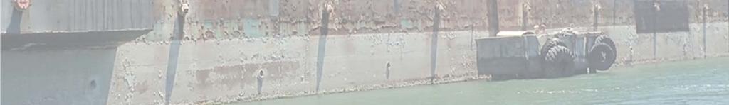


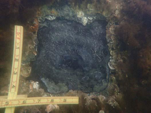

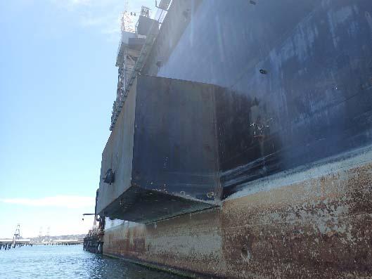
70 GHD, Inc. Port of San Francisco Dry Dock 2 Underwater Condition Assessment FINAL REPORT San Francisco, CA June 2017 Safeco Plaza, 1001 Fourth Avenue, Suite 4305 Seattle, Washington


71 July 25, 2017 Collins Job No Mr. Craig Lewis Facilities Service Line Leader GHD, Inc. 655 Montgomery Street, Suite 1010 San Francisco, CA RE: Port of San Francisco Dry Dock 2 Underwater Condition Assessment Dear Mr. Lewis, Collins Engineers, Inc. (Collins) is pleased to submit this FINAL document: Dry Dock 2 Underwater Condition Assessment FINAL Report. This document is in accordance with the scope of services contained in the Agreement for Professional Services with GHD, Inc., dated April 26, This report includes: condition assessment for the underwater hull components of Dry Dock 2, project drawings, ultrasonic thickness gauge measurement results, typical photographs, and definitions. Thank you for the opportunity to participate in the execution of this important project. Very truly yours, COLLINS ENGINEERS, INC. Daniel Stromberg, P.E. Engineer of Record I hereby certify that this engineering document was prepared by me or under my direct supervision and that I am duly Licensed Professional Engineer under the laws of the State of California. Daniel G. Stromberg, P.E. #C75133 My license renewal date is 12/31/2017 Pages or sheets covered by this seal: Entire Report
72 Table of Contents Page Executive Summary 1 Section 1 Introduction Project Personnel Inspection Procedures 3 Section 2 Underwater Condition Assessment Dry Dock 2 Hull Mooring Dolphins 5 Section 3 Repair Recommendations 6 APPENDICES Appendix A Inspection Drawings 7 Appendix B Photographs 11 Appendix C Ultrasonic Thickness Measurements 18 Appendix E Definitions 23 GHD, Inc. i Dry Dock 2
73 Underwater Conidtion Assessment EXECUTIVE SUMMARY INSPECTION DATA Date June 12-15, 2017 Total Dive Time hours Daily Start Time 07:30 Number of Dives 11 Daily Finish Time 17:00 Water Temp. 60 F Total Site Time 40 hours Ambient Temp. 73 F Water Velocity 1 fps Dive Mode Surface Supplied Air Maximum Depth 50 Dolphin 4 Underwater Visibility Location Latitude: Longitude: Substructure Units Inspected Inspection Personnel 3 ft N W Dry Dock Hull and Mooring Dolphin Piles Dive Supervisor: Daniel Stromberg/Richard Hunt Diver/Tender: Adam Cox Diver/Tender: John Strub Diver/Tender: Michael Spencer CRITICAL FINDINGS None SIGNIFICANT OBSERVATIONS Dry Dock 2 hull, below water, average section loss of 9% and a maximum section loss of approximately 16% for the steel plates originally 1/2 in. thick. Dry Dock 2 hull, below water, average section loss of 8% and a maximum section loss of approximately 15% for the steel plates originally 7/16 in. thick. MAINTENANCE WORK RECOMMENDATIONS Monitor the steel section loss below water for the hull of Dry Dock 2 and the mooring dolphin piles. GHD - TECI Dry Dock 2 Page 1

74 Underwater Condition Assessment 1.0 INTRODUCTION An Underwater Condition Assessment of Dry Dock 2 was conducted from June 12th to June 15th, 2017 at the Port of San Francisco Pier 70 to evaluate the current underwater condition of the Dry Dock 2 hull. Overall, the Dry Dock 2 hull was found to be in SATISFACTORY to FAIR condition with primarily just minor corrosion-related deterioration that consisted of section loss as ascertained by ultrasonic thickness gauge measurements. The inspection was performed in accordance with the ASCE Manual for Underwater Investigations, including the associated rating guidelines and definitions, which are located in Appendix D. Currently, Dry Dock 2 is positioned and held in place by four mooring dolphins (labeled D1 through D4 from south to north) with an access platform to the dry dock at the Puglia Shipyard (Pier 70) at the Port of San Francisco. The dry dock is orientated with its longitudinal axis from south to north with an apron for access at the south end of the dry dock. Refer to Photographs 1 through 3 in Appendix B for overall views of Dry Dock 2 and to Photographs 4 through 7 in Appendix B for views of the four mooring dolphins. A map with an approximate location of the limits of inspection is shown below in Figure Figure Facility Vicinity Map Dry Dock 2 Source: Google Earth GHD - TECI Dry Dock 2 Page 2
75 Underwater Condition Assessment 1.1 PROJECT PERSONNEL The underwater inspection was performed by a four-person team consisting of four engineer-divers, two of whom were registered California Professional Engineers (P.E.). At any given time during the inspection process, the team makeup consisted of a dive supervisor, an inspection diver, a backup (safety) diver, and a tender. The primary points of contact for the project are presented in Table Project Representatives. Table Project Representatives Entity Name Contact Information Port of San Francisco GHD - TECI Collins Engineers, Inc. Collins Engineers, Inc. Source: Collins Engineers, Inc. Matthew Bell, P.E., S.E. Civil Engineer Engineering Division Craig Lewis, P.E., S.E. Senior Project Manager Daniel Stromberg, P.E. Team Leader and Project Manger Adam Cox Assistant Project Manager Pier 1, The Embarcadero San Francisco, CA matthew.n.bell@sfport.com (415) Montgomery Street, Suite 1010 San Francisco, CA craig.lewis@ghd.com (415) Fourth Ave, Suite 4305 Seattle, WA dstromberg@collinsengr.com (312) Fourth Ave, Suite 4305 Seattle, WA acox@collinsengr.com (206) INSPECTION PROCEDURES The underwater inspection consisted of Level I, II and III level inspection intensities, as defined by the ASCE Manual for Underwater Investigations and included in Appendix D. At the time of the inspection, the dry dock ballast tanks were emptied of water such that Dry Dock 2 had a vertical draft of approximately 7 ft. Level II cleanings to gather Level III ultrasonic thickness (UT) gauge readings (measurements) of remaining steel thickness were taken along belt lines spaced every 100 ft along the longitudinal (north/south) axis of the dry dock as shown in Appendix A, Sheet S-01. A fixed line was placed along each belt line to guide the engineer-diver while taking UT readings and to ensure that UT readings could be gathered along the same line during future inspections for comparison purposes. Level I visual/tactile inspection for the entire submerged portion of the hull was performed by using a tether line linking the engineer-diver to each of the belt lines to the guide line to facilitate sweeping of the hull for 50 ft in both directions away from the belt line parallel to the longitudinal (north/south) axis of the hull. Engineer-divers were deployed from the D/V James Eads which was moored to the starboard (west) side of the dry dock at each belt line. 2.0 UNDERWATER CONDITION ASSESSMENT GHD - TECI Dry Dock 2 Page 3
76 Underwater Condition Assessment 2.1 DRY DOCK 2 HULL Overall, the submerged portion of the hull of Dry Dock 2 was deemed to be in satisfactory to fair condition, based on the established rating criteria presented in the ASCE Manual for Underwater Investigations, and there were no deterioration levels or other conditions observed during the underwater inspection of the hull that would warrant immediate concern. In general, the submerged surfaces of the hull exhibited 100% coverage of a dense layer of marine growth, which consisted of a 1 to 2 in. thick layer of harder shell growth directly on the steel, overlaid by a 3 to 4 in. thick layer of softer sponge and anemone growth. On the underside of the hull, the extent and thickness of the marine growth was fairly consistent throughout, and the Level I underwater inspection of the hull did not reveal any inconsistencies in the growth uniformity that would suggest any deformation or other localized damage in the underlying steel hull surface. As for the submerged sides of the hull (generally 6 to 7 ft of vertical surface based on the dry dock draft), the marine growth tailed off to mostly just include the harder shell growth layer, which was again generally uniform with no evidence of any localized hull damage. As previously indicated, the layer of marine growth was quite dense overall, and typically was difficult to remove during the Level II and III inspection efforts, with the shell growth anchorage membranes strongly adhered to the steel surfaces. Between the marine growth and the remaining competent steel of the hull, there was typically between 1/16 and 1/4 in. of dark grey corrosion by-product that was also strongly adhered and added to the marine growth removal difficulty. Removal of the marine growth and corrosion by-product to the extent typically possible revealed steel hull surfaces that were at times rather smooth, although the majority of the time, the removal process revealed steel surfaces that were rough due to pitting of the steel. In general, the coverage of the pitting ranged between 25% and 100% of the cleaned steel surface, and the pitting was mostly light in extent with typical penetrations up to 1/32 in. and some 1/16 in. deep pits in rare instances. Refer to Photographs 8 and 9 in Appendix B for some typical views of the submerged Dry Dock 2 hull conditions. During the underwater inspection of the submerged Dry Dock 2 hull surfaces, a large number of ultrasonic remaining steel thickness measurements were taken as part of the Level II and III inspections. These included measurements taken along transverse (east/west) belt lines at specific locations along the dry dock, to provide a consistent sampling set of measurements for assessing the average and range of remaining steel thicknesses, as well as taken at many arbitrary locations during the overall Level I inspection process, for comparison purposes with the specific data set and to possibly identify any out-of-range measurements (lower than typical) that could warrant further investigation. Overall, the specific thickness measurements taken, as well as the arbitrary measurements for that matter, were fairly consistent throughout with regard to the amount of steel section loss that has occurred due to corrosion-related deterioration. Based on available original design plans and other information for Dry Dock 2 provided by the Port of San Francisco, the dry dock hull is believed to have been originally constructed with a mix of 1/2 and 7/16 in. thick steel plate, with design plans and/or other information indicating 1/2 in. thick plate along a 32 ft wide strip down (north/south) the center of the hull and the remaining hull constructed of 7/16 in. thick steel. Based on this presumed hull plate thickness layout, where the original thickness was purported to have been 1/2 in. thick, the remaining steel thicknesses generally ranged between in., suggesting no appreciable loss of original section to date, and in., indicating an approximate 16% loss of original steel section. Overall, for the 1/2 in. thick mid-portion of the dry dock hull, the average remaining thickness was in the range of in., which suggests on average that approximately 9% of original steel thickness has been lost to corrosion-related deterioration. As for the portions of hull that were purported to have been originally 7/16 in. thick, similar corrosionrelated loss measurement results were obtained, although there were also some measurements gathered that were larger than the believed original, suggesting that 1/2 in. thick steel plate may have used instead. Where measurements were consistent with a 7/16 in. original thickness, the remaining steel thicknesses generally ranged between in., again suggesting no appreciable loss of original section to date, and in., indicating an approximate 15% loss of original steel section. Overall, GHD - TECI Dry Dock 2 Page 4
77 Underwater Condition Assessment for the 7/16 in. thick portions of the dry dock hull, the average remaining thickness was in the range of in., indicating an approximate 8% of original steel thickness has been lost to corrosionrelated deterioration. Regarding the portions of hull that were purported to have been originally constructed with 7/16 in. thick plate, it should again be mentioned that some measurements were obtained in excess of 7/16 in., which could be an indication that thicker plate was used as part of the actual as-built condition. In particular, many of the larger-than-expected were very consistent with the measurements obtained from known 1/2 in. thick plate; that is, those measurements from the centerline of the dry dock, suggesting that 1/2 in. thick plate may have ultimately been used in lieu of 7/16 in. thick plate. Assuming this to be the case, where 1/2 in. thick plate may have been used, the overall amount of section loss percentages was very similar to what was derived for the 1/2 in. thick center portion of the dry dock hull, with maximum losses of approximately 16% and on average losses of approximately 9%. The exact locations and thickness measurements of the assumed thicker than expected plates are tabulated in Appendix C. Regarding the current measured amounts of section loss for the underwater dry dock hull steel, it can be taken that a range of between approximately 10% and 20% of the original steel thickness has been lost to corrosion-related deterioration over a timeframe of around 48 years. This in turn equates to between in. (I mil) and in. (2 mil) of steel thickness loss per year. These values tend to be on the low side of what could be expected based on the recently published ASCE Waterfront Facilities Inspection & Assessment Standard Practice Manual. However, the values do tend to be in the neighborhood of suggested values for steel with adequate cathodic protection, which it is believed could be the case for Dry Dock 2 (port representatives indicated that an impressed current cathodic protection system is in place and operational for Dry Dock 2). Nonetheless, using a linear regression for future corrosion rates and assuming that future corrosion influences and deterrents will be same as to what has been present throughout the past, it can be suggested that another 40 years or so could transpire before remaining underwater steel thicknesses begin to pose concerns. 2.2 MOORING DOLPHINS The mooring dolphin piles were found to be in mostly satisfactory condition with no notable defects observed at the time of the inspection and minor to isolated areas of moderate section loss measured. The mooring dolphins along the west side of Dry Dock 2 are labeled D1 through D4 from south to north. It should be noted that the the inspection of the underwater condition of the steel piles at the mooring dolphins was not outlined in the scope of services agreed upon prior to dive operations; however, the inspection of the submerged portions of the mooring dolphin piles was added to the original scope during an on-site pre-inspection meeting with representatives from the Port of San Francisco. Each mooring dolphins consists between 14 or in. diameter plumb and 24 in. battered steel pipe piles that are located under a concrete cap. The dolphins are position south to north along the west side of the dry dock at approximately 200 ft intervals. Refer to Appendix A, Sheets S1 and S2 for details on the locations and pile layouts of the mooring dolphins. Typically, the steel piles had 100% marine growth coverage that consisted of a 2 in. thick layer of hard marine growth, overlaid with 1 in. of soft marine growth from top of the pile down 15 ft. The marine growth from 15 ft below the top of pile to the channel bottom consisted of a 1 in. thick layer of hard marine growth and a sporadic 1/2 in. thick layer of soft growth over the top of the hard growth. Also similar to the dry dock hull, the layer of marine growth was difficult to remove during the Level II and III inspection efforts, with the shell growth anchorage membranes strongly adhered to the steel surfaces. Between the marine growth and the remaining competent steel of the shell piles, there was typically between 1/16 and 1/4 in. of dark grey corrosion by-product that was also strongly adhered and added to the marine growth removal difficulty. Removal of the marine growth and corrosion by-product to the extent typically possible revealed the steel surfaces of the shell piles to be mostly rough due to varying degrees of pitting of the steel. In general, the coverage of the pitting ranged between 25% and 100% of the cleaned steel surface, and the pitting was generally light to GHD - TECI Dry Dock 2 Page 5
78 Underwater Condition Assessment moderate in extent with typical penetrations of up to 1/32 in. and maximum penetrations of 1/16 in. Refer to Photographs 10 and 11 in Appendix B for some typical views of the submerged mooring shell pile conditions During the underwater inspection of the submerged portions of the mooring dolphin shell piles, ultrasonic remaining steel thickness measurements were taken as part of the Level II and III inspections. These included measurements taken at representative piles at each of the dolphins at three specific elevations including within in the tidal zone, at mid water column depth, and near the channel bottom. Overall, it should be noted that the specific thickness measurements taken were fairly consistent throughout with regard to the amount of steel section loss that has occurred due to corrosion-related deterioration. From the mooring dolphin design information available, it is believed that originally the shell piles supporting the dolphins had a 1/2 in. pile wall thickness. Based on this presumed pile wall thickness, the remaining steel thicknesses measured for the submerged portion of the piles generally ranged between in., suggesting no appreciable loss of original section to date, and in., indicating an approximate 30% loss of original steel section. It should be noted that one measurement of lesser thickness; that is, in., was recorded; however, it was deemed to be an abnormality and highly inconsistent with all of the other measurements. Overall, given the 1/2 in. wall thickness of the mooring dolphin piles, the average remaining thickness was in the range of in., which suggests on average that approximately 13% of original steel thickness has been lost to corrosion-related deterioration. 3.0 REPAIR RECOMENDATIONS As previously indicated, for the submerged portions of the hull of Dry Dock 2, as well as for the submerged portions of the piles of the mooring dolphins, the estimated amount of loss of the original steel sections is to the lower side of what could be expected, given the time in service, and therefore, based on the results of the underwater inspection, these elements are considered to be in satisfactory to fair condition at this time. There were no indications of any excessive general or localized section loss identified for the hull steel, and therefore, there are no concerns or need for repairs for the below water dry dock hull or dolphin pile steel at this time. The only recommendation would be to establish an acceptable schedule for future hull and pile inspections to monitor the rate of corrosion-related section loss. In that regard, the industry standard for underwater inspection at 6 year intervals would be reasonable, unless there is a drastic change in prevailing environmental conditions, including a loss or reduction in cathodic protection capacity, or if significant damage is suspected. It is also recommended that during future inspections the remaining thickness of the steel hull and piles be measured with the use of an ultrasonic thickness measuring device as a means of providing a fairly accurate and reliable way of comparing remaining thickness values and assessing corrosion-related section loss rates. GHD - TECI Dry Dock 2 Page 6
79 Underwater Condition Assessment Appendix A Inspection Drawings GHD - TECI Dry Dock 2 Page 7
80 Page 8
81 Page 9

82 Page 10
83 Underwater Condition Assessment Appendix B Photographs GHD - TECI Dry Dock 2 Page 11


84 Underwater Condition Assessment Photograph 1 : Overall View of Dry Dock 2, Looking East. Photograph 2 : Overall View of the West Wingwall of Dry Dock 2, Looking Southeast. GHD - TECI Dry Dock 2 Page 12


85 Underwater Condition Assessment Photograph 3 : Overall View of the East Wingwall of Dry Dock 2, Looking Southwest. Photograph 4 : Overall View of Mooring Dolphin 1, Looking East. GHD - TECI Dry Dock 2 Page 13


86 Underwater Condition Assessment Photograph 5 : Overall View of Mooring Dolphin 2, Looking East. Photograph 6 : Overall View of Mooring Dolphin 3, Looking East. GHD - TECI Dry Dock 2 Page 14


87 Underwater Condition Assessment Photograph 7 : Overall View of Mooring Dolphin 4, Looking Southeast. Photograph 8 : Underwater View of the Typical Marine Growth on the Bottom of the Hull. GHD - TECI Dry Dock 2 Page 15
.")
88 Underwater Condition Assessment Photograph 9 : Underwater View of the Typical Steel Conidtion on the Hull. Photograph 10 : Underwater View of the Typical Marine Growth on the Steel Pipe Piles (Southeast Pile at Dolphn 4 Shown). GHD - TECI Dry Dock 2 Page 16
.")
89 Underwater Condition Assessment Photograph 11 : Underwater View of the Typical Steel Condition on the Steel Pipe Piles (Southeast Pile at Dolphn 4 Shown). GHD - TECI Dry Dock 2 Page 17
90 Underwater Condition Assessment Appendix C Ultrasonic Thickness Measurements GHD - TECI Dry Dock 2 Page 18
91 Underwater Condition Assessment Table 1 C 01 Steel Hull Thickness Measurements Steel Hull Thickness Measurements Belt Line Location Design Thickness (in.) Measured Thickness (in.) Difference ( ) Percent Loss (%) A % B % C % D % E % F % G % H % I % A % B % C % D % E % F % G % H % I % A % B % C % D % E % F % G % H % I % A % B * % (8%) C * % (7%) D * % (8%) E % F % G % GHD - TECI Dry Dock 2 Page 19
92 Underwater Condition Assessment Table 1 C 01 Steel Hull Thickness Measurements Belt Line Location Design Thickness (in.) Measured Thickness (in.) Difference ( ) Percent Loss (%) H % I % A % B % C % D % E % F % G % H % I % A % B % C % D % E % F * % (12%) G * % (11%) H * % (10%) I * % ( 4%) A * % (12%) B * % (7%) C * % (10%) D * % (9%) E % F * % (10%) G * % (10%) H * % (12%) I * % (10%) A * % (12%) B * % ( 3%) C * % (4%) D * % (3%) E % F % G % GHD - TECI Dry Dock 2 Page 20
93 Underwater Condition Assessment Table 1 C 01 Steel Hull Thickness Measurements Belt Line Location Design Thickness (in.) Measured Thickness (in.) Difference ( ) Percent Loss (%) 8 H % I % A % B % C % D % 9 E % F % G % H % I % *Measurement Value suggested that 1/2 in. thick plate may have originally used in lieu of 7/16 in. plate Values in the () represents the percentage of section loss assuming a 1/2 in. plate. GHD - TECI Dry Dock 2 Page 21
94 Underwater Condition Assessment Dolphin Pile Design Thickness (in.) Table 2 C 02 Mooring Dolphin Pile Thickness Measurements Measurement (in.) Steel Pipe Pile Thickness Measurements Mudline Mid Height Waterline Difference ( ) Percent Loss (%) Measurement (in.) Difference ( ) Percent Loss (%) Measurement (in.) Difference ( ) Percent Loss (%) SE % % % NW % % % SW % % % NE % % % SE % % % NW % % % SE % % % NW % % % GHD - TECI Dry Dock 2 Page 22
95 Underwater Condition Assessment Appendix D Definitions GHD - TECI Dry Dock 2 Page 23

96 Underwater Condition Assessment DEFINITIONS Exposure Zones the five zones along a pile s length as shown in Figure D-1: Atmospheric, Splash, Tidal, Submerged, and Mud. Figure C-1 - Exposure Zones USPL-GMS Figure 5 GHD - TECI Dry Dock 2 Page 24

97 Underwater Condition Assessment Table D-1 ASCE 130 Waterfront Facilities Inspection & Assessment Table GHD - TECI Dry Dock 2 Page 25
98 Underwater Condition Assessment Figure D-2 ASCE 130 Waterfront Facilities Inspection & Assessment Figure GHD - TECI Dry Dock 2 Page 26
99 Underwater Condition Assessment Figure D-2 ASCE 130 Waterfront Facilities Inspection & Assessment Figure Inspection Level Scope of Work Overview Detectable Defects in Steel Level I Visual or tactile inspection of underwater components without removal of marine growth Level II Partial marine growth removal of a statistically representative sample typically 10% of all components. Level III Nondestructive testing (NDT) or partially destructive testing (PDT) of a statistically sample typically 5% of all components. May consist of PDT of wood and remaining thickness measurements of steel components. Extensive corrosion and holes Severe mechanical damage Moderate mechanical damage Corrosion pitting and loss of section Thickness of material Electrical potentials for cathodic protection Source: ASCE Manual, Underwater Investigations Standard Practice Manual, GHD - TECI Dry Dock 2 Page 27


100
101 Appendix C Photos GHD-Telamon Engineering Consultants, Inc Port of San Francisco Dry Dock #2 Structural Assessment Report 38


102 Pontoon Deck Photos 1. On pontoon deck, looking north 2. Pontoon deck and keel blocks 3. Close up of deflection and pitting 4. Numerous through holes 5. Failed epoxy repair of sheared plate at stiffeners 6. Failed coating at doubler plates


103 Wingwall Photos 7. East wingwall 8. Inner shell at pontoon level with through hole 9. Inner shell with repaired kick plates 10. South end of west wingwall 11. Sponson at west wingwall 12. Recently replaced outer shell panels


104 13. Outer shell panels note recently replaced plates and corroding existing plates Apron Photos 14. Outer shell panels ready for installation 15. South apron, above 16. South apron, level 17. South apron, below 18. South apron, below


105 19. North apron 20. North apron, below
106 Appendix D Pontoon Deck Inspection Field Notes GHD-Telamon Engineering Consultants, Inc Port of San Francisco Dry Dock #2 Structural Assessment Report 39
107
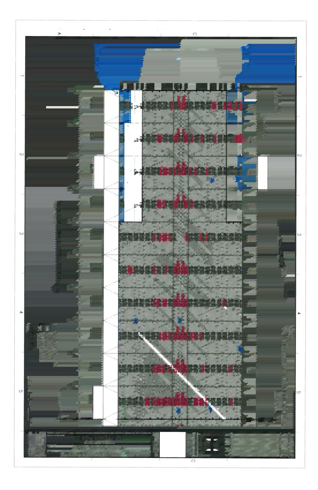
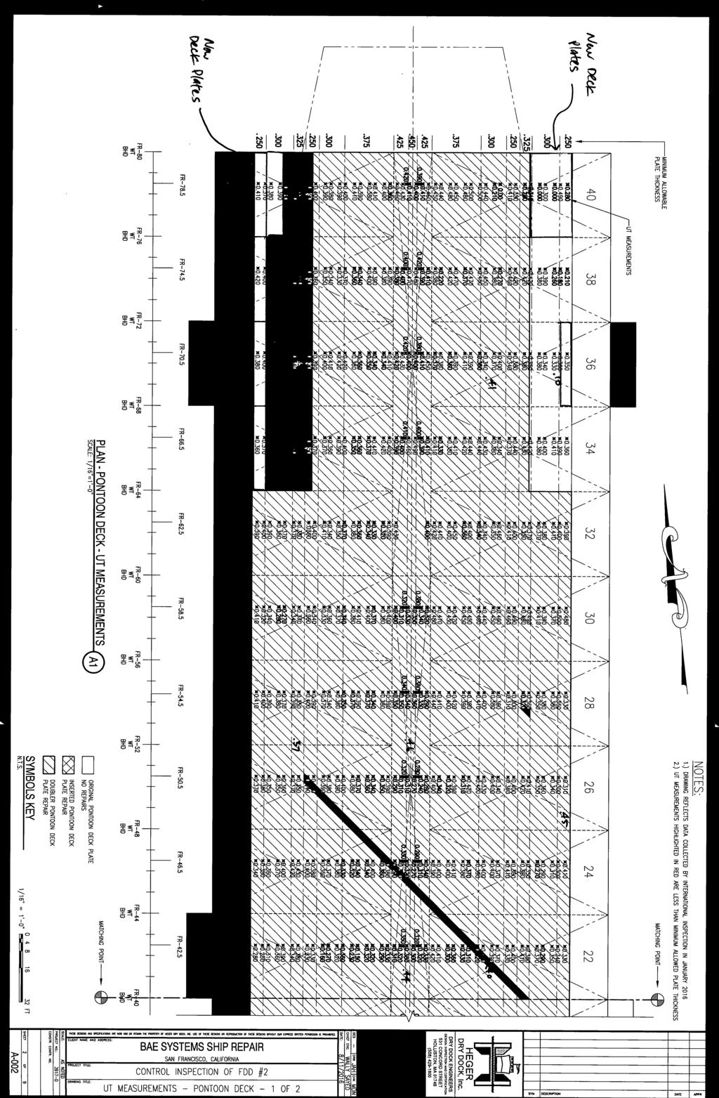


108
HEGER DRY DOCK, INC Structural/Marine Engineers 531 Concord Street Holliston, MA Tel Fax
 HEGER DRY DOCK, INC Structural/Marine Engineers 531 Concord Street Holliston, MA 01746 Tel 508-429-1800 Fax 508-429-1811 16 87L December 7, 2016 Attention: Eddie Goldman, Senior Dockmaster (eddie.goldman@baesystems.com)
DRY DOCK NO. 2 ANALYSIS OF WINGWALL SHELL PLATE AS SURVEYED THICKNESSES
 DRY DOCK NO. 2 ANALYSIS OF WINGWALL SHELL PLATE AS SURVEYED THICKNESSES Prepared for BAE SYSTEMS SAN FRANCISCO SHIP REPAIR Foot of 20 th Street San Francisco, CA 94107-3005 Prepared by Bruce S. Rosenblatt
Hull Surveys for Liquefied Gas Carriers
 (May 2007) (Rev.1 Nov 2007) (Rev.2 Mar 2009) (Rev.3 July 2011) Hull Surveys for Liquefied Gas Carriers CONTENTS 1. General 1.1 Application 1.2 Definitions 1.3 Repairs 1.4 Thickness measurements and close-up
Hull Surveys for General Dry Cargo Ships
 (June 2002) Hull Surveys for General Dry Cargo Ships CONTENTS 1. General 1.1 Application 1.2 Definitions 1.3 Repairs 2. Special Survey 2.1 Schedule 2.2 Scope 2.2.1 General 2.2.2 Dry Dock Survey 2.2.3 Tank
Modjeski and Masters, Inc. Consulting Engineers 04/18/06 St. Croix River Bridge 3D Analysis Report Introduction
 Introduction This memo presents a summary of a three dimensional (3D) analysis of the Organic concept for the proposed St. Croix River bridge project. The Organic concept has several attributes that are
Ore Carriers Part 4, Chapter 11
 Section 1 Section 1 General 2 Materials and protection 3 Longitudinal strength 1.2 Structural configuration and ship arrangement 1.2.1 The requirements contained in the Chapter apply to single deck ships
Ship Structure Committee Case Study
 Member Agencies: American Bureau of Shipping Defence Research and Development Canada Maritime Administration Military Sealift Command Naval Sea Systems Command Society of Naval Architects & Marine Engineers
3. INSPECTION FINDINGS
 3. INSPECTION FINDINGS Pier 40 is in overall Poor condition with 22% of the H-piles rated Major and 35% of the H-piles rated Severe, primarily due to severe corrosion within the splash zone at the top
RULES FOR CLASSIFICATION OF FLOATING DOCKS
 CHINA CLASSIFICATION SOCIETY RULES FOR CLASSIFICATION OF FLOATING DOCKS 2009 Effective from July 1 2009 Beijing CONTENTS CHAPTER 1 GENERAL...1 Section 1 GENERAL PROVISIONS...1 Section 2 SCOPE AND CONDITIONS
Corrigenda 1. Rule Editorials
 COMMON STRUCTURAL RULES FOR BULK CARRIERS JULY 2012 Corrigenda 1 Rule Editorials Notes: (1) These Rule Corrigenda enter into force on 1st July 2012. (2) These Rule Corrigenda should be read in conjunction
Rules for the Classification of. Dredgers
 017 Rules for the Classification of Dredgers KR 017 Rules for the Classification of Dredgers RB-04-E KR APPLICATION OF "RULES FOR THE CLASSIFICATION OF DREDGERS" 1. Unless expressly specified otherwise,
It is recommended that repairs be undertaken to bring these steel connections back to original design strength on a priority basis.
 August 30, 2016 REF: 16LET019 Address: Attention: Subject: BAE Systems, San Francisco Ship Repair Foot of 20 th Street San Francisco, CA 94107 Mr. Justin Gleaton, Dockmaster Dry Dock No. 2 Dolphin & Stair
Kodathoor Gangadharan Midhun
 Kodathoor Gangadharan Midhun 7 th EMship cycle: September 2016 February 2018 Master Thesis Structural Design and Stability of a 6,000 ton Capacity Floating Dock as per DNVGL Rules Supervisor: Dr. Zbigniew
STEEL BARGES 1991 RULES FOR BUILDING AND CLASSING. NOTICE NO. 8 September The following Rule Changes are EFFECTIVE AS OF 1 JANUARY 2003.
 RULES FOR BUILDING AND CLASSING STEEL BARGES 1991 NOTICE NO. 8 September 2002 The following Rule Changes are EFFECTIVE AS OF 1 JANUARY 2003. SECTION 7 PART B MAIN FRAMING TANK BARGES 7B.3 Double Skin Tank
Office Building-G. Thesis Proposal. Carl Hubben. Structural Option. Advisor: Dr. Ali Memari
 Office Building-G Thesis Proposal Structural Option December 10, 2010 Table of Contents Executive Summary... 3 Introduction... 4 Gravity System...4 Lateral System:...6 Foundation System:...6 Problem Statement...
INSPECTION GRADING CRITERIA FOR THE ABS HULL INSPECTION AND MAINTENANCE PROGRAM (HIMP)
") INSPECTION GRADING CRITERIA FOR THE ABS HULL INSPECTION AND MAINTENANCE PROGRAM (HIMP) OUR MISSION The mission of ABS is to serve the public interest as well as the needs of our members and clients by
INSPECTION GRADING CRITERIA FOR THE ABS HULL INSPECTION AND MAINTENANCE PROGRAM (HIMP) OUR MISSION The mission of ABS is to serve the public interest as well as the needs of our members and clients by
1.15 Chemical Tanker Longitudinal corrugated bulkhead (vertical type).
.") Table A.1 corrugated bulkhead s Case Ship Type Damage Location 1.1 Chemical Tanker Longitudinal corrugated bulkheads (horizontal type) in way of mid cargo area. 1.2 Product Tanker Transverse corrugated
Table A.1 corrugated bulkhead s Case Ship Type Damage Location 1.1 Chemical Tanker Longitudinal corrugated bulkheads (horizontal type) in way of mid cargo area. 1.2 Product Tanker Transverse corrugated
Not Repeating the Past - A Case Study of Fatigue Fracture in Midship Cargo Tanks
 Not Repeating the Past - A Case Study of Fatigue Fracture in Midship Cargo Tanks Ryan Salamati ABS, Hamburg Germany Dr. Michael B. Kennedy Hellespont Ship Management GmbH & Co. KG, Hamburg Germany Abstract
Design of Catamaran Ship Main Deck and Bulkhead to Withstand the Crane Load
 International Journal of Engineering Research and Development e-issn: 78-067X, p-issn: 78-800X, www.ijerd.com Volume 8, Issue 3 (August 013), PP. 31-41 Design of Catamaran Ship Main Deck and Bulkhead to
Load capacity rating of an existing curved steel box girder bridge through field test
 109 Dongzhou Huang Senior Engineer IV TS Transportation Design South Florida Atkins North America Load capacity rating of an existing curved steel box girder bridge through field test Abstract This paper
Part 7 Ships of Special Service
 2017 Rules for the Classification of Steel Ships Part 7 Ships of Special Service 2017 Guidance Relating to the Rules for the Classification of Steel ships Part 7 Ships of Special Service Rules Guidance
Stress-Laminated / Steel T-Beam Bridge System
 Stress-Laminated / Steel T-Beam Bridge System David A. Apple and Clinton Woodward, New Mexico State University Abstract The stress-laminated timber bridge deck has been successfully used for short span
FMB15678 Steel Deck Cargo Barge
 FMB15678 Steel Deck Cargo Barge 2 Barges, originally built in 2012 to the specification below are now available for purchase. Section 1 General 1.1 Intent & Definition This specification together with
Third Avenue New York, NY. Structural Concepts/ Structural Existing Conditions Report September 30, Michelle L.
 Executive Summary The structural design of 554-556 Third Avenue is composed of two way concrete slabs supported by a system of columns spanning an average of twenty feet. Lateral loads are resisted by
SPECIFICATIONS FOR THE CONSTRUCTION OF NEW PASSENGER EQUIPMENT CARS PREFACE
 SPECIFICATIONS FOR THE CONSTRUCTION OF NEW PASSENGER EQUIPMENT CARS Standard ADOPTED 1939; ADVANCED TO STANDARD, 1945. PREFACE The specifications have been prepared on the basis that they will be used
GUIDANCE FOR CHECKING THE STRUCTURE OF BULK CARRIERS
 INTERNATIONAL MARITIME ORGANIZATION 4 ALBERT EMBANKMENT LONDON SE1 7SR Telephone: 020 7735 7611 Fax: 020 7587 3210 IMO E Ref. T1/2.01 MSC/Circ.1117 24 June 2004 GUIDANCE FOR CHECKING THE STRUCTURE OF BULK
Technical Information
 Subject Format Revision of Condition Evaluation Report (CER) To whom it may concern Technical Information No. TEC-1092 Date 17 November 2016 When Special is carried out for ships applying Enhanced Program(ESP),
Information Paper on Cargo Tank Corrugated Bulkhead Damages of Double Hull Tankers
 Tanker Structure Co-operative Forum Information Paper on Cargo Tank Corrugated Bulkhead Damages of Double Hull Tankers SUMMARY The paper reviews current corrugated bulkhead design practise and provides
VARIOUS TYPES OF SLABS
 VARIOUS TYPES OF SLABS 1 CHOICE OF TYPE OF SLAB FLOOR The choice of type of slab for a particular floor depends on many factors. Economy of construction is obviously an important consideration, but this
research report The Strength of Stiffened CFS Floor Joist Assemblies with Offset Loading RESEARCH REPORT RP REVISION 2006
 research report The Strength of Stiffened CFS Floor Joist Assemblies with Offset Loading RESEARCH REPORT RP03-6 2003 REVISION 2006 American Iron and Steel Institute The Strength of Stiffened CFS Floor
PRESENT STATUS AND FUTURE DEVELOPMENT FOR THE DESIGN AND CONSTRUCTION OF DOUBLE HULLS TANKERS
 PRESENT STATUS AND FUTURE DEVELOPMENT FOR THE DESIGN AND CONSTRUCTION OF DOUBLE HULLS TANKERS PRESENTED BY: MITSUBISHI HEAVY INDUSTRIES, LTD. AT TANKER STRUCTURAL CO-OPERATIVE FORUM 2000 SHIPBUILDERS MEETING
ASSESSING THE EFFECTS OF CORROSION ON THE MECHANICAL INTEGRITY OF A PIPELINE SUSPENSION BRIDGE
 ASSESSING THE EFFECTS OF CORROSION ON THE MECHANICAL INTEGRITY OF A PIPELINE SUSPENSION BRIDGE Chris Alexander Stress Engineering Services, Inc. Houston, Texas Henry Cartaya, P.E. Energistix, Inc. The
Steel Design Guide Series. Steel and Composite Beams with. Web Openings
 Steel Design Guide Series Steel and Composite Beams with Web Openings Steel Design Guide Series Steel and Composite Beams with Web Openings Design of Steel and Composite Beams with Web Openings David Darwin
Structural Design of a Containership Approximately 3100 TEU According to the Concept of General Ship Design B-178
 Structural Design of a Containership Approximately 3100 TEU According to the Concept of General Ship Design B-178 W.Souadji, Zbigniew Sekulski, B.Hamoudi 1 Abstract The design developed in this work is
Jonathan R. Torch Technical Report 2 Columbia University. Technical Report 2. Pro-Con Structural Study of Alternate Floor Systems
 Technical Report 2 Pro-Con Structural Study of Alternate Floor Systems Columbia University Broadway & 120 th Street, New York, NY Jonathan R. Torch Pennsylvania State University Architectural Engineering
THE FORENSIC MEDICAL CENTER
 THE FORENSIC MEDICAL CENTER Image courtesy of Gaudreau, Inc. TECHNICAL REPORT #2 OCTOBER 26, 2007 KEENAN YOHE STRUCTURAL OPTION DR. MEMARI FACULTY ADVISOR EXECUTIVE SUMMARY Image courtesy of Gaudreau,
RULES PUBLICATION NO. 62/P HULL SURVEYS OF GENERAL DRY CARGO SHIPS July
 RULES PUBLICATION NO. 62/P HULL SURVEYS OF GENERAL DRY CARGO SHIPS 2017 July Publications P (Additional Rule Requirements) issued by Polski Rejestr Statków complete or extend the Rules and are mandatory
Damage Stability of Inland Towboats
 University of New Orleans ScholarWorks@UNO Senior Honors Theses Undergraduate Showcase 5-2014 Damage Stability of Inland Towboats Kyle Stephen Tyson University of New Orleans Follow this and additional
THE FORENSIC MEDICAL CENTER
 THE FORENSIC MEDICAL CENTER Image courtesy of Gaudreau, Inc. TECHNICAL REPORT #1 OCTOBER 5, 2007 KEENAN YOHE STRUCTURAL OPTION DR. MEMARI FACULTY ADVISOR EXECUTIVE SUMMARY Image courtesy of Gaudreau, Inc.
RULES FOR CLASSIFICATION Inland navigation vessels. Part 5 Ship types Chapter 1 Cargo vessels. Edition December 2015 DNV GL AS
 RULES FOR CLASSIFICATION Inland navigation vessels Edition December 2015 Part 5 Ship types Chapter 1 The content of this service document is the subject of intellectual property rights reserved by ("DNV
5. CONCLUSIONS, RECOMMENDATIONS, COST ESTIMATES
 5. CONCLUSIONS, RECOMMENDATIONS, COST ESTIMATES 5.1 CONCLUSIONS In general, Pier 40 is in overall Poor condition. The allowable uniform live load rating for the pier has been significantly reduced from
Influence of corrosion-related degradation of mechanical properties of shipbuilding steel on collapse strength of plates and stiffened panels
 Towards Green Marine Technology and Transport Guedes Soares, Dejhalla & Pavleti (Eds) 2015 Taylor & Francis Group, London, ISBN 978-1-138-02887-6 Influence of corrosion-related degradation of mechanical
Executive Summary RPT-SPE December 21. Old Spences Bridge No Inspection Report
 Executive Summary The Old Spences Bridge was constructed in 1931 and crosses the Thompson River providing a link between Highway 8 and Highway 1 in the Community of Spences Bridge, BC. In 1962, a new bridge
Safety Documents > Safety Manual > Scaffolds
 Safety Documents > Safety Manual > Scaffolds D. Scaffolds 1. General Requirements for All Scaffolds a. Scaffolds shall be furnished and erected in accordance with this standard for persons engaged in work
MSC Guidelines for Review of Structural Plans for Wooden Vessels
 K. B. Ferrie, CDR, Chief, Hull Division References: a. Lloyd s Register Rules and Regulations for the Classification of Yachts and Small Craft (Amended to 1983) b. 1943 ABS Rules for Building and Classing
Flotation Docking Systems, Inc.
 GENERAL SPECIFICATIONS The following data outlines the design calculations and specifications around which Flotation Docking Systems, Inc. products are constructed. The use of such information for contract
Downloaded from MILITARY STANDARD
 INCH-POUND MIL-STD-2189 (SH) 22 JANUARY 1988 MILITARY STANDARD DESIGN METHODS FOR NAVAL SHIPBOARD SYSTEMS REINFORCEMENT OF OPENINGS IN STRUCTURE OF SURFACE SHIPS OTHER THAN IN PROTECTIVE PLATING AMSC N/A
National Maritime Center
 National Maritime Center Providing Credentials to Mariners (Sample Examination) Page 1 of 12 Choose the best answer to the following Multiple Choice Questions. 1. To have the ultimate authority for a mobile
Structural Design of 38m Special Purpose Vessel in Aluminium Alloy By Murat Tosun
 Structural Design of 38m Special Purpose Vessel in Aluminium Alloy By Murat Tosun Supervisor: Prof. Dario Boote, University of Genoa Reviewer: Prof. André Hage, University of Liege Intermarine & Rodriquez
Ministry of Forests & Range
 Ministry of Forests & Range DRAWING SCHEDULE DRAWING No. / MODEL TYPE STD-EC-040-01 STD-EC-040-02 STD-EC-040-03 STD-EC-040-04 STD-EC-040-05 STD-EC-040-06 STD-EC-040-07 STD-EC-040-08 DESCRIPTION REV. DATE
IMO ANY OTHER BUSINESS. Verification of technical standards for ship construction. Submitted by the United Kingdom
 INTERNATIONAL MARITIME ORGANIZATION E IMO SUB-COMMITTEE ON SHIP DESIGN AND EQUIPMENT 48th session Agenda item 24 DE 48/INF.6 17 December 2004 ENGLISH ONLY ANY OTHER BUSINESS Verification of technical standards
STEEL REACTION FRAME
 STEEL REACTION FRAME Kyle Coleman, CEE Laboratory Manager Andrew Myers, Assistant Professor Jerome F. Hajjar, Professor and Chair, Director, STReSS Laboratory Department of Civil and Environmental Engineering,
Franklin Square Hospital Center Patient Tower
 Thomas Weaver Structural Option Franklin Square Hospital Center Patient Tower Baltimore, MD Thomas Weaver Structural Option AE 481W Senior Thesis Consultant: Professor M. Kevin Parfitt 12/14/2009 Page
Appendix D.1. Redundancy Analysis of Composite Spread Box Girder Superstructures under Vertical Loads
 Appendix D.1 Redundancy Analysis of Composite Spread Box Girder Superstructures under Vertical Loads By Jian Yang, Feng Miao and Michel Ghosn Contents 1. Introduction...1 2. Structural Modeling...3 2.1
Structural Design Engineers 120 Montgomery Street, Suite 1410 San Francisco, California / Fax 415/
 120 Montgomery Street, Suite 1410 San Francisco, California 94104 415/781-1505 Fax 415/781-2718 sde@sdesf.com Rajendra Sahai, SE Principal John W. Laws, SE Principal Steven Lepisto, SE Principal STRUCTURAL
Technical Assignment 1 10/8/03
 Executive Summary Technical Assignment 1 10/8/03 The is 55 story high-rise condominium being built off the northern Miami coast. The structural design presented in this building is a direct result of its
SAMPLE TC6K Elevator Design Summary. Order No PO-47201
 SAMPLE TC6K Elevator Design Summary 900 RR 620 S., Ste C206 Austin TX 78734 (512) 266-6200 voice (512) 266-6210 fax SAMPLE CCR TC6K Elevator Design Summary - Elevator System Design Parameters Nominal Height
Brent Ellmann Structural Option 200 Minuteman Park, Andover, MA Structural Consultant: Dr. Hanagan
 Brief Building Overview: 200 Minuteman Park stands as a 200,000 square foot Class A office building in Andover, Massachusetts, worth roughly $15,000,000. Although the building has a large square footage,
ROOFING APPLICATION STANDARD (TAS) No. 102(A)-95
 No. 102(A)-95") ROOFING APPLICATION STANDARD (TAS) No. 102(A)-95 TEST PROCEDURE FOR STATIC UPLIFT RESISTANCE OF MECHANICALLY ATTACHED, CLIPPED, RIGID, ROOF SYSTEMS (For Methods of Mechanical Attachment Excluding Clips,
ROOFING APPLICATION STANDARD (TAS) No. 102(A)-95 TEST PROCEDURE FOR STATIC UPLIFT RESISTANCE OF MECHANICALLY ATTACHED, CLIPPED, RIGID, ROOF SYSTEMS (For Methods of Mechanical Attachment Excluding Clips,
Investigation for the Removal of Steel Tie Rods in a Historic Segmental Arch Floor
 Investigation for the Removal of Steel Tie Rods in a Historic Segmental Arch Floor J. Lan 1, R. Gilsanz 2, and M. Lo 3 1 Gilsanz Murray Steficek, LLP, 129 West 27 th St., 5 th Floor, New York, NY 10001
CHAPTER III DYNAMIC BEHAVIOR OF A LABORATORY SPECIMEN
 CHAPTER III DYNAMIC BEHAVIOR OF A LABORATORY SPECIMEN To address the vibration response of a long span deck floor system, an experiment using a specimen that resembles the conditions found in the in-situ
OCTAGONAL SHAPE REDUCES AIRPLANE HANGAR COSTS
 OCTAGONAL SHAPE REDUCES AIRPLANE HANGAR COSTS While a square hangar would have been simpler to design, an octagonal building substantially reduced life cycle costs By Charles Sacre, P.E. THE PROGRAM FOR
(4) Production inspection is the inspection that must initially be conducted on each newly manufactured IBC.
 Production inspection is the inspection that must initially be conducted on each newly manufactured IBC.") Subpart O Testing of IBCs 178.800 Purpose and scope. This subpart prescribes certain testing requirements for IBCs identified in subpart N of this part. [Amdt. 178 103, 59 FR 38074, July 26, 1994, as amended
Subpart O Testing of IBCs 178.800 Purpose and scope. This subpart prescribes certain testing requirements for IBCs identified in subpart N of this part. [Amdt. 178 103, 59 FR 38074, July 26, 1994, as amended
Introduction to Structural Analysis TYPES OF STRUCTURES LOADS AND
 AND Introduction to Structural Analysis TYPES OF STRUCTURES LOADS INTRODUCTION What is the role of structural analysis in structural engineering projects? Structural engineering is the science and art
Chlorine Contact Basin at Keegan s Bayou WWTP, Houston, TX
 Glass Steel, InC. 1 FIBERGLASS BAFFLE WALL SYSTEMS Chlorine Contact Basin at Keegan s Bayou WWTP, Houston, TX Glass Steel, Inc. PO Box 7155 The Woodlands, TX 77387-7155 18468 FM 1314 Conroe, TX 77302 (281)
Dead Loads (psf): Concrete Floor Slab on Metal Deck 45 psf Mechanical and Ceiling 7 psf Miscellaneous 5 psf Exterior Wall 80 psf
: Concrete Floor Slab on Metal Deck 45 psf Mechanical and Ceiling 7 psf Miscellaneous 5 psf Exterior Wall 80 psf") CODES AND REQUIREMENTS The structural design of Northbrook Corporate Center was based on the International Building Code 2003, which incorporates many of the provisions of ASCE 7. The lateral load design
CODES AND REQUIREMENTS The structural design of Northbrook Corporate Center was based on the International Building Code 2003, which incorporates many of the provisions of ASCE 7. The lateral load design
USE OF SALE CHARTS IN DETERMINING MOMENT AND SHEAR
 APPENDIX C USE OF SALE CHARTS IN DETERMINING MOMENT AND SHEAR FM 5-277 When a simple horizontal beam is loaded, it deflects, or bends downward, and the horizontal fibers in the lower part of the beam are
OTC Abstract. Introduction
 OTC 15315 An Innovative "No Hot Work" Approach to Hull Repair on In-Service FPSOs Using Sandwich Plate System Overlay Stephen J. Kennedy, James Bond, and Dale Braun, Intelligent Engineering Limited; Peter
SECTION 415 REINFORCING FOR CONCRETE
 SECTION 415 REINFORCING FOR CONCRETE Module 5 August 2018 Release 10, Module 5 1 Release 10, August 2018 5-1 415 1 Description Furnish and place steel and fiber reinforced polymer (FRP) reinforcing of
IACS Common Structural Rules for Double Hull Oil Tankers, January Background Document
 IACS Common Structural Rules for Double Hull Oil Tankers, January 2006 Background Document SECTION 9/2 DESIGN VERIFICATION STRENGTH ASSESSMENT (FEM) NOTE: - This TB is published to improve the transparency
THE COMMON STRUCTURAL RULES INITIAL DESIGNS AND FUTURE DEVELOPMENTS
 THE COMMON STRUCTURAL RULES INITIAL DESIGNS AND FUTURE DEVELOPMENTS Gary Horn, ABS, USA Dan Cronin, ABS, Singapore Abstract This paper will discuss the design of oil tankers built to the IACS Common Structural
M. C. Yaksh, Ph.D., PE NAC International T. Chung SAIC
 Evaluation of the Paducah Tiger Overpack for Accident Conditions Abstract M. C. Yaksh, Ph.D., PE NAC International T. Chung SAIC An evaluation of the accident conditions for the Paducah Tiger Overpack
Right Additional Design Procedures
 ShipRight Design and construction Additional Design Procedures Assessment of Steel Hatch Covers Using Finite Element Analysis July 2007 ABCD Lloyd s Register Marine Business Stream 71 Fenchurch Street
RESOLUTION MSC.158(78) (adopted on 20 May 2004) AMENDMENTS TO THE TECHNICAL PROVISIONS FOR MEANS OF ACCESS FOR INSPECTIONS
 (adopted on 20 May 2004) AMENDMENTS TO THE TECHNICAL PROVISIONS FOR MEANS OF ACCESS FOR INSPECTIONS") RESOLUTION MSC.158(78) MSC.lS8(78) (adopted on 20 May 2004) AMENDMENTS TO THE TECHNICAL PROVISIONS FOR MEANS OF ACCESS FOR INSPECTIONS THE MARITIME SAFETY COMMITTEE, RECALLING Article 28(b) of the Convention
RESOLUTION MSC.158(78) MSC.lS8(78) (adopted on 20 May 2004) AMENDMENTS TO THE TECHNICAL PROVISIONS FOR MEANS OF ACCESS FOR INSPECTIONS THE MARITIME SAFETY COMMITTEE, RECALLING Article 28(b) of the Convention
Brent Ellmann Structural Option 200 Minuteman Park, Andover, MA Structural Consultant: Dr. Hanagan
 Structural Design: Goals: The original design of 200 Minuteman Drive was dictated largely by Brickstone Properties, the building s owner. The new design of 200 Minuteman Drive, with additional floors,
Euro NCAP Mobile Progressive Deformable Barrier Face Specification Draft Version December 2017 TB 022
 Technical Bulletin Euro NCAP Mobile Progressive Deformable Barrier Face Specification Draft Version 1.0.1 TB 022 Title Euro NCAP MPDB Specification Version v1.0.1 Draft Document Number TB022 Author J Ellway
Hull damage experience in CSR tankers
 MARITIME Hull damage experience in CSR tankers TSCF SBM, Busan October 2016 Ivar Håberg Senior Principle Surveyor, DNV GL SAFER, SMARTER, GREENER Using data to identify improvement opportunities for the
Scope. resistance expressed as a moment
 ROOFING APPLICATION STANDARD (TAS) No. 102-95 TEST PROCEDURE FOR STATIC UPLIFT RESISTANCE OF MECHANICALLY ATTACHED, RIGID ROOF SYSTEMS [For Mechanically Attached, Rigid Roof Systems Accompanied by a Clip,
GUIDELINES FOR THE INFORMATION TO BE INCLUDED IN A SHIP CONSTRUCTION FILE
 E 4 ALBERT EMBANKMENT LONDON SE1 7SR Telephone: +44 (0)20 7735 7611 Fax: +44 (0)20 7587 3210 Ref. T4/3.01 MSC.1/Circ.1343 2 June 2010 GUIDELINES FOR THE INFORMATION TO BE INCLUDED IN A SHIP CONSTRUCTION
Analysis of Paved Shoulder Width Requirements
 Analysis of Paved Shoulder Width Requirements Research Report RR-14-02 Prepared for Texas Department of Transportation Maintenance Division Prepared by Texas A&M Transportation Institute Emmanuel Fernando
Rules for the Classification of. Steel Barges
 2017 Rules for the Classification of Steel Barges KR 2017 Rules for the Classification of Steel Barges Rules 2017 Guidance Relating to the Rules for the Classification of Steel Barges Guidance 2017 Rules
ShipRight Design and Construction
 ShipRight Design and Construction Additional Design Procedures Assessment of Steel Hatch Covers Using Finite Element Analysis January 2018 Working together for a safer world Document History Document Date:
IACS Common Structural Rules for Bulk Carriers and Oil Tankers Complying with IMO GBS. Gang Wang, IACS HP member Busan,Korea, October 2016
 TSCF 2016 Shipbuilders Meeting IACS Common Structural Rules for Bulk Carriers and Oil Tankers Complying with IMO GBS Gang Wang, IACS HP member Busan,Korea, 26 27 October 2016 1 Content 1 Introduction 2
SECTION PLATE CONNECTED WOOD TRUSSES
 SECTION 06173 PLATE CONNECTED WOOD TRUSSES PART 1 GENERAL 1.01 SUMMARY A. Section Includes: 1. Shop fabricated wood trusses for roof and floor framing. 2. Bridging, bracing, and anchorage. B. Related Sections:
SHIP & OFFSHORE STRUCTURES
 SHIP & OFFSHORE STRUCTURES 1 Module Description and Goals The Engineering module offers students an opportunity to: Examine the fundamental principles of engineering behind structure design of ships and
Inner Harbor Navigational Canal Lock Replacement Shallow Draft GRR. Annex 5: Sector Gate versus Miter Gate Analysis
 Inner Harbor Navigational Canal Lock Replacement Shallow Draft GRR Annex 5: Sector Gate versus Miter Gate Analysis February 1st, 2016 Prepared by MVN ED Structures Branch Page 1 of 9 1.0 BACKGROUND 1.1
181 Fremont San Francisco, CA. Tech Report 3 10/17/2014. PSUAE Structural Option Advisor: Dr. Thomas Boothby
 181 Fremont San Francisco, CA Tech Report 3 10/17/2014 PSUAE Structural Option Advisor: Dr. Thomas Boothby Caroline Klatman cjk5258@psu.edu October 17, 2014 Dr. Thomas Boothby The Pennsylvania State University
Ship Design and Construction Training Module
 Ship Design and Construction Training Module NSRP Joint Panel Meeting September 11, 2012 Steve Scholler and T.D. Huang Ingalls Shipbuilding Outline Introduction Thin Steel Design and Construction Difficulties
OUR COMPANY OUR WARRANTY OUR GUARANTEE
 DESIGN MANUAL-USA FRAMED BY QUALITY BUILT WITH SUCCESS OUR COMPANY At International Beams Inc. we take pride in providing our customers with premium quality products and services. Our full range of engineered
Structural Performance of 8-inch NRG Concrete Masonry Units. Report Compiled for: Niagara Regional Group. Date: January 28, 2013
 Structural Performance of 8-inch NRG Concrete Masonry Units Report Compiled for: Niagara Regional Group Date: January 28, 2013 Report Prepared by: Dr. Shawn Gross, Associate Professor Dr. David Dinehart,
Floating Bridges. Corps of Engineers Field Manual. Military Pontoon Bridge
 Floating Bridges Corps of Engineers Field Manual War Department 1909 Military Pontoon Bridge Hood Canal Transverse Pontoon Option Bersoysund Floating Bridge Nordhordland Floating Bridge Continuous Pontoon
16. Design of Pipeline Structures.
 16. Design of Pipeline Structures. a. General. 1) The following guidelines are for the design of structures for water and sewer pipelines including structural concrete and miscellaneous metals design.
E-Beam HD. Cold-Formed Insulated Composite Structural Elements. Engineering/Analysis Report
 E-Beam HD Cold-Formed Insulated Composite Structural Elements Engineering/Analysis Report February 2012 Engineering/Analysis Report February 2012 Prepared for: 309 Noble Cliff Langley, WA 98260 Prepared
INSTALLATION MANUAL FOR MODULAR EXPANSION JOINT (LG SYSTEM)
") INSTALLATION MANUAL FOR MODULAR EXPANSION JOINT (LG SYSTEM) TABLE OF CONTENTS 1. INTRODUCTION TO THE MODULAR EXPANSION JOINT 1.1 Purpose 1.2 How They Work 1.3 Movement Capacity 1.3.1 Longitudinal Direction
INSTALLATION MANUAL FOR MODULAR EXPANSION JOINT (LG SYSTEM) TABLE OF CONTENTS 1. INTRODUCTION TO THE MODULAR EXPANSION JOINT 1.1 Purpose 1.2 How They Work 1.3 Movement Capacity 1.3.1 Longitudinal Direction
Marina Coast Water District Marina, CA Steel Reservoir #2
 WATER TANK INSPECTION REPORT Prepared for the Marina Coast Water District Marina, CA Steel Reservoir #2 October 26, 2005 490 Industrial Park Road Deep River, CT 06417 Tel: (860) 526-2610 Fax:(860) 526-5018)
Interior Hangers. Application
 Application Interior bridge deck hangers are typically fabricated using two heavy duty sheet metal end clips that have been electrically resistance welded to an appropriate sized wire or formed metal connecting
Design Development of Corrugated Bulkheads
 Design Development of Corrugated Bulkheads Hayato Suga Tatsuya Hayashi Shinichiro Ishimaru Koki Hirano Tsubasa
TEST AND ANALYSIS OF A SHORT-SPAN RAILWAY BRIDGE
 Proceedings of the 6th International Conference on Mechanics and Materials in Design, Editors: J.F. Silva Gomes & S.A. Meguid, P.Delgada/Azores, 26-30 July 2015 PAPER REF: 5756 TEST AND ANALYSIS OF A SHORT-SPAN
Metal to the metal. by W. Lee Shoemaker, Ph.D., P.E. and Vincent E. Sagan, P.E. and Dale Nelson
 Metal to the metal Re-covering existing metal roof systems requires diligence by W. Lee Shoemaker, Ph.D., P.E. and Vincent E. Sagan, P.E. and Dale Nelson Metal roof systems always have been known to have
Thesis Proposal 12/13/06
 Photo courtesy of OTO Development, http://www.otodevelopment.com/ Dr. Memari Thesis Advisor Thesis Proposal 12/13/06 Executive Summary Structural System The in, is an eleven story hotel complex which reaches