ME Computer Integrated Manufacturing Mechanical Engineering UNIT IV PART-A
|
|
|
- Hubert Cook
- 6 years ago
- Views:
Transcription
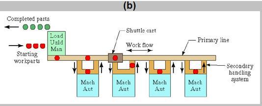
1 ME Computer Integrated Manufacturing Mechanical Engineering UNIT IV Flexible Manufacturing System (FMS) Automated Guided vehicle system (AGVS) PART-A 1. Define FMS. A Flexible Manufacturing System is an integrated approach to automating a production system with a view to accommodate fast response to product changes. It is designed to be flexible so that it can manufacture a variety of products at relatively low volumes, with minimum lead-time between product changes. 2. Define FMC (Nov/ Dec 2015) The simplest, hence most flexible type of FMS is a flexible manufacturing cell. It consists of one or more CNC machine tools, general purpose or of special design interfaced with automated material handling and tool changers. FMC s are capable of automatically machining a wide range of different work piece. They are usually employed in one off and small batch production as independent machining centers, but are frequently the starting point for FMS. 3. List the benefits of FMS. (Nov/ Dec 2015) (Nov/Dec 2016) Reduced cycle times; Lower work-in-process (WIP) inventory; Low direct labour costs; Ability to change over to different parts quickly; Improved quality of product (due to consistency); Higher utilization of equipment and resources (Utilization better than standalone CNC machines); Quicker response to market changes; Reduced space requirements; Ability to optimize loading and throughput of machines. 4. List down the major elements of FMS Production systems, Support systems; materials handling systems; automated storage and retrieval systems, buffer storing of parts; chip removal and washing systems; computer control systems. 5. List the function of FMS computer control system. Workstation control, Material Handling system control, Work piece Monitoring, Tool control, Failure Diagnosis & Safety Monitoring, Production control, Reporting etc., 6. List the types of data associated with the FMC A typical FMC system handles four different types of data: Master data, control data, status data and general management data. These data are generated from CAD, CAP and CAM functions. 7. Write any two applications of FMS. Gantry (Robot) for Loading and Unloading (Automatic Part Changing); Automatic Tool Change Systems; automated storage and retrieval systems; Tool Condition Monitoring System 8. List the typical FMS layout subsystems. a)automatic storage and retrieval system; b) CNC machines; c) Work piece carriers (AGV s); d) Palletizing station; e) Washing station; f) Tool presetting station; g) Computer control system. 9. What are the types of FMS layout? In-line layout; Loop layout; Ladder layout; Open field layout; Robot centered layout.
2 10. List some MHS system. Materials handling includes parts transfer from conveyors and palletization. Robots perform well in these applications as well as handling fragile components and heavy ones and parts that are very hot or very cold. The tasks can be simple or complex involving tracking in one or two axes or a moving conveyor. Some robots equipped with multiple tooling can handle more than one part at a time. A variety of end effectors have been used including mechanical grippers, magnets and vacuum cups, conveyor, cranes, industrial trucks, monorails automated guided vehicle, industrial robots. 11. State the purpose of primary and secondary material handling system. Primary handling system - establishes the basic layout of the FMS and is responsible for moving work parts between stations in the system. Secondary handling system - consists of transfer devices, automatic pallet changers, and similar mechanisms located at the workstations in the FMS. 12. Differentiate between FMS and FMC. a)a FMC has two or three machine, while an FMS has four or more machine. b) FMS generally include non-processing workstations. However, FMC does not any non-processing workstations. c) The computer control systems of an FMS are generally larger and more sophisticated than that of a FMC. 13. What are the different types of flexibility? a)machine flexibility b) Production flexibility c) Mix flexibility d) Volume flexibility e) Expansion flexibility f) Routing flexibility g) Product flexibility. 14. Write the different components of FMS? (1) Workstations, (2) material handling and storage system, and (3) computer control system. In addition, even though an FMS is highly automated, (4) people are required to manage and operate the system.

 Flexible")
3 PART B 1. Explain the component of FMS and FMS layout configuration. (Nov/Dec 2016) Flexible Manufacturing System Layout Configurations
4
 A buffer storage system for queues of workpieces at the machines (e.g., pallets) A transfer system to load and unload the machines (e.")
5 2.Write notes on various materials handling equipment that are commonly used in a FMS A FMS typically needs several materials handling systems to service the machines. A transport system to move workpieces into and out of the FMS (e.g. overhead conveyors, gantry systems, AGV s, RGV s) A buffer storage system for queues of workpieces at the machines (e.g., pallets) A transfer system to load and unload the machines (e.g. robots, transfer fixtures) For these systems to work effectively, they must be synchronized with the machine operations. The location and movement of workpieces must be tracked automatically. This is done by using sensors on the materials handling system and workstations. They may be either contact devices (e.g. switches) or non-contact devices (e.g. optical, tags or proximity devices). Automatic Guided Vehicles (AGV) AGV is one of the widely used types of material handling device in an FMS. These are battery-powered vehicles that can move and transfer materials by following prescribed paths around the shop floor. They are neither physically tied to the production line nor 90 driven by an operator like forklift. Such vehicles have on-board controllers that can be programmed for complicated and varying routes as well as load and unload operations. The computer for the materials handling system or the central computer provides overall control functions, such as dispatching, routing and traffic control and collision avoidance. AGV s usually complementing an automated production line consisting of conveyor or transfer systems by providing the flexibility of complex and programmable movement around the manufacturing shop. Advantages of using AGV systems in FMS (i) Flexibility: The route of the AGV s can be easily altered, expanded and modified, simply by changing the guide path of the vehicles. This is more cost effective than modifying fixed conveyor lines or
6 rail guided vehicles. It provides direct access materials handling system for loading and unloading FMS cells and accessing the automated storage and retrieval system. (ii) Real time monitoring and control: Because of computer control, AGV s can be monitored in real time. If the FMS control system decides to change the schedule, the vehicles can be re-routed and urgent requests can be served. AGV s are usually controlled through wires implanted on the factory floor. The control is effected using a variable frequency approach. Radio control, an alternative to in-floor mounted communication lines, permits two way communications between the on-board computer and a remote computer, independent of where the vehicle is i.e. whether it is in the parking place or whether it is in motion. To issue a command to a vehicle, the central computer sends a bit stream via its transmitter using frequency shift keying methods to address a specific vehicle. The signal transmitted from the base station is, therefore, read by the appropriate vehicle only. The vehicle is also capable of sending signals back to the remote controller, to report the status of the vehicle, vehicle malfunction, battery status, and so on. (iii) Safety: AGV s can travel at a slow speed but typically operate in the range 10 to 70 m/min. They have on-board microprocessor control to communicate with local zone controllers which direct the traffic and prevent collisions between vehicles as well as the vehicle and other objects. A bumper is attached to some designs of AGV s to prevent collision. AGV s may also incorporate warning lights, fire safety interlocks and controls 91 for safety in shops. During design, the use of simulation can help detect whether there are enough vehicles to perform the necessary load, unload and transportation tasks and thus optimize the utilization of the AGV system. Because these vehicles have to work in a tandem with highly organized FMS cells as well as with automated warehouses under computer control, their level of performance will affect the entire efficiency of the FMS. Automated Storage and Retrieval Systems A key part of any materials handling system is storage. Major advances have been made in recent years to automate the storage and retrieval of product and materials by employing sophisticated materials handling machines, high-density storage techniques and computer control. Such systems come in a variety of forms and sizes depending on the materials handling and storage job that has to be done. They often take the form of automated warehouses which use automatic storage and retrieval systems, conveyors and computers to control the materials handling machines and to track and control the inventory. The characteristics of such warehouses include: (i) (ii) (iii) High density storage (in some cases, large, high-rise rack structures) Automated handling systems (such as elevators, storage and retrieval carousels and conveyors). ( Materials tracking systems (using optical or magnetic sensors) In such a storage system, the computer can keep track of a large number of different parts, products and materials and can assign bin locations to optimize the use of storage space. When such a system is tied into the production control system, parts and materials can be replenished as they are consumed on the factory floor, keeping the work in process (WIP) to a minimum.
7 3.Explain about FMS workstation. List the applications of FMS. (Nov/ Dec 2015) FMS workstation types Workstation Load/Unload Machining Other Assembly Description Physical interface between the FMS and the rest of the factory, it is where raw parts enter the system, and completely-processed parts exit the system. Loading and unloading can be performed manually by personnel, or it can be automated as part of the material handling system. Should be designed to permit the safe movement of parts, and may be supported by various mechanical devices (e.g. cranes, forklifts). The station includes a data entry unit and monitor for communication between the operator and computer system, regarding parts to enter the system, and parts to exit the system. In some FMSs, various pallet fixtures to accommodate different pallet sizes may have to be put in place at load/unload stations. The most common FMS application occurs at machining stations. These are usually CNC machine tools with appropriate automatic tool changing and tool storage features to facilitate quick physical changeover, as necessary. Machining centres can be ordered with automatic pallet changers that can be readily interfaced with the FMS part handling system. Machining centres used for non-rotational parts; for rotational parts turning centres are used. Milling centres may also be used where there are requirements for multi-tooth rotational cutters. Other possible stations may be found in specific industries, such as for example sheet metal fabrication, which has stations for press-working operations, such as punching, shearing, and certain bending and forming processes. Forging is another labour intensive operation which may be broken into specific station categories, such as heating furnace, forging press, and trimming station. Associated with assembly FMSs, the assembly operation usually consists of a number of workstations with industrial robots that sequentially assemble components to the base part to create the overall assembly.
8 Supporting They can be programmed to perform tasks with variations in sequence and motion pattern to accommodate the different product styles assembled in the system. Supporting stations may include inspection stations where various inspection tasks may be carried out. Co-ordinate measuring machines, special inspection probes, and machine vision may all be used here. Other supporting stations may include pallet and part washing stations for particularly dirty or oily FMSs, and temporary storage stations for both parts and pallets. Applications of FMS The applications of FMS are realized in the following areas: 1.Machining, 2. Assembly, 3. Sheet-metal press working 4. Forging, 5. Plastic injection molding, 6. Welding, 7. Textile machinery manufacture, and 8.Semiconductor component manufacture
9 4.Explain the functions of FMS Computer control system. Computer Control System The third major component of FMS is the computer control system.in flexible manufacturing systems, computers are required to control theautomated and semi-automated equipment and to participate in the overallcoordination and management of the manufacturing system. A typical FMS computer control system consists of a central computer and microcomputers controlling the individual machines and other components. The centralcomputer coordinates the activities of the components to achieve smooth overalloperation of the system. Functions of a FMS Computer Control System The functions that are performed by the FMS computer control 1. Workstation/processing station control. Computer control system controls the operations of the individual processing or assembly stations in the factory. For controlling the machining centres, CNC is used. 2. Distribution of control instructions to workstations. A direct numerical control (DNC) is used in a machining FMS to download the part programs to the machines. The DNC computer control system also stores the programs, allows entering and editing of programs, and performs the other DNC functions. 3. Production control. Computer control system, based on data entered into the computer, helps to take decisions on part mix and rate of input of the various parts onto the system. As a part of the production control, computer control system communicates instructions to the operators for performing different tasks on different work units. Also certain production scheduling functions are accomplished atihe manufacturing site by the computer control system. Structure of FMS Application Software Systems Fig.4.14 illustrates the modular structure of the FMS application software for system control, presented by Human Resources The fourth and final component in the FMS is human labour. Like in any other manufacturing approaches, the operations of the FMS are also managed by human labours. In FMS, human labors are needed to perform the following functions: 1. To load raw work parts into the system. 2. To unload finished work parts from the system. 3. For tool changing and tool setting. 4. For equipment maintenance and repair. 5. To furnish NC part programming in a machining system. 6. To program and operate the computer system. 7. To accomplish overall-management of the system. 5. write short notes on the following. 1) Quantitative Analysis of Flexible Manufacturing Systems
10 2) Benefits of FMS Flexible manufacturing system 3) Advantages of Flexible Manufacturing Systems 4)Disadvantages of Flexible Manufacturing Systems Quantitative Analysis of Flexible Manufacturing Systems FMSs can be analysed under four different approaches; these are: Deterministic models that is, models that are used to gain starting estimations of system performance, but not for complex phenomena, such as the build-up of queues and other dynamics that can impair system performance. Queuing models these attend to issues of queuing not examined in deterministic models, and they examine various simple system configurations. Discrete event simulation often used in the latter parts of system design to determine the most accurate methods for modelling specific attributes of the FMS. Characteristics handled here include layout configuration, number of pallets in the system, and production scheduling rules. Other techniques this is a hold-all title that includes various approaches, from mathematical programming, heuristic approaches, and a number of operational research techniques. Benefits of FMS Flexible manufacturing system benefits are listed as follows: Reduction of inventories throughout the complete chain of manufacturing including work-in-progress Reduction of lead time by 40% Improved machine utilization by 30% Reduction of labour times by 30% Reduction of direct and indirect labour costs Increased management control over the entire manufacturing process Substantially reduced scrap levels. The ability to adapt quickly to new work pieces. Advantages n Faster, lower-cost changes from one part to another which will improve capital utilization n Lower direct labor cost, due to the reduction in number of workers FMS Introduction and Description 11 n Reduced inventory, due to the planning and programming precision n Consistent and better quality, due to the automated control n Lower cost/unit of output, due to the greater productivity using the same number of workers n Savings from the indirect labor, from reduced errors, rework, repairs and rejects Disadvantages n Limited ability to adapt to changes in product or product mix (ex. machines are of limited capacity and the tooling necessary for products, even of the same family, is not always feasible in a given FMS) n Substantial pre-planning activity n Expensive, costing millions of dollars n Technological problems of exact component positioning and precise timing necessary to process a component n Sophisticated manufacturing systems

11 6. With neat schematic layout explain an example offmsimplemented manufacturing system.
12 7.What are the bottleneck model and the extended bottleneck model? Major issues of planning for the creation of FMSs include: part family considerations; processing requirements; physical characteristics of the workparts; and production volume. Major issues of design for the creation of FMSs include: workstation type; consideration of the variations in process routings and FMS layout; choice of material handling system; work-in-process and storage capacity decisions; tooling choices; and pallet fixture considerations. FMSs are generally analysed under deterministic and queuing methodologies in the early stage of system; while, in later stages, discrete event simulation is used to handling general system characteristics. Other techniques, including mathematical programming, heuristics, and operational research techniques, are used to capture various realties within the FMS, as necessary. In deterministic modelling, the bottleneck model is a model that examines the production system s upper limit, given that the product mix flowing through the FMS is fixed. The bottleneck model allows us to determine initial values for the average workload of individual stations in the FMS, the average number of transports in the system, and the average workload of the material handling system. The extended bottleneck model assumes a closed queuing network in which there are always a certain number of workparts in the FMS. There are two cases considered in the extended bottleneck model, where the number of parts in the system is the critical determinant. 8. What is AGV? Explain its Components? An AGVS is a system consisting of an unmanned, battery-powered vehicle, a guidance system, and other associated components. The vehicle can be programmed to pick up a load at one location and take it to another location automatically. Unlike a conveyor, AGVs are actual vehicles that can take materials/products from one location to another using a variety of different paths based on traffic in the area and programming that is done that will direct the AGV down the path that will get it to its location the quickest. Since AGVs are unmanned, they can run 24 hours a day, 7 days a week, and 365 days a year. AGVSs can use a PLC to set its course and to stop the AGV when it has an object in close proximity that it might hit. Several types of AGVSs can be used to do the necessary work and various components on the AGVS help it perform its functions and keep it and the objects/people around it safe.
13 AGVS Components AGVSs use many different components to assist it in getting a load from point A to point B. These components range from sensors on the vehicle used to detect objects or people in the near vicinity to the control system that is used to control the actions of the vehicle as well as interface it with the server that receives the work requests. See Appendix A for pictures of a magnet scanner and a laser scanner. Controller The controller typically consists of a microprocessor that is used to gather data and make decisions based on a program. The controller tells the vehicle how fast to go, where to go, where to turn, and when to stop. The controller gathers information from its guidance system about its location and about routes that are available. Information is also collected from the sensors to stop the vehicle, sound warnings, and maneuver if obstructions are in the vehicles path. New programs can be loaded into the controller to tell the vehicle of new routes that must be taken due to new obstructions such as construction areas. See Figure 1 for an example of a controller configuration. A controller will maintain communication with another PC/workstation that supervises all of the AGV controllers. The supervisor controls traffic, tells the AGV where the load is to be picked up and where to take it. When the routing of the vehicles must change, a user can install the program on the supervisor, and the supervisor can download it to the individual AGV controllers. Wireless Steering Motor Steering Motor Driver Modem Command and Diagnosis Termination Running Motor Running Motor Driver Barrier Detector Off-track and Guided Signal Detector AGV Controller Cruising Antenna Manual Control Device Signpost Identifying Sensor SENSORS Control Configuration (Zhan 426) Sensors come in all shapes and sizes and have a variety of different uses from temperature sensors to proximity sensors. A temperature sensor on an AGV can monitor battery temperature to prevent the battery from being damaged. Proximity sensors can be used to determine if there are objects in the path of the AGV such as inanimate obstructions or personnel. Although guidance systems will be discussed later, it is important to note that guidance systems use sensors to determine position by sensing targets on the wall, chemicals on the floor, magnets in the floor, etc.
14 RF Modem Since AGVs are not wired directly to a supervisor, and the AGV must know where loads are and where to drop them off, an RF modem is typically used for communication between the controller on the AGV and the supervisor computer. Without this modem, the AGV would have to be controlled manually, which defeats a large portion of the purpose (reduction in manning) behind using AGVS. Another possible scenario that doesn t involve an RF modem requires information be transmitted through a wire in the floor. This requires a wire-guided guidance system, which, as will be discussed later, limits the flexibility of the system. AGVS Vehicles Many different vehicles can be used to move loads. These vehicles differ in functionality and capacity. When choosing which vehicle is best for the application, consult with the system designers and analyze the process and vehicles available to determine which will work best. These vehicles include but are not limited to forklifts; tow trucks, conveyor decks, and scissor lift transporters. See Appendix A for pictures of some of the vehicles. 9.How the issue of Routing of AGVSis managed? Guidance systems are used to get an AGV from point A to point B. However, once the guidance system is chosen, how does one determine the path the guidance system uses to get the AGV from point A to point B? The routing of an AGVS defines the path the guidance system will take based on a number of design factors from the number of vehicles to be used to the amount of space available to run the AGV. Number of Vehicles The number of vehicles that are used in an AGVS depend on several factors. To determine the number of vehicles that are required in a system, the following analysis by Singh can be used. Dd = total average loaded travel distance De = total average empty travel distance Ndr = number of deliveries required per hour Th = loading and unloading time Tt = traffic factor that accounts for blocking of vehicles and waiting of vehicles in line and at intersections. If there is no congestion (that means there is only one vehicle in the system), the traffic factor is one. However, when more vehicles are involved, the traffic factor value will certainly be less than one. Normally, Tf lies between 0.85 and 1. v = vehicle speed Tdv = total time per delivery vehicle Nd = number of deliveries per vehicle per hour
15 T dv D v d De Th v N 60T d T dv f Number of Automated guided vehicles = Ndr/Nd (Singh ) Floor Space The amount of floor space that is available restricts the number of vehicles that can pass through an area at the same time. There might be areas that only one vehicle can pass through, or there may be areas where all the vehicles could pass each other at the same time if required. Floor space availability will affect the guide path due to some areas having more obstructions or foot traffic than others will. Although there is no equation that determines the amount of floor space required for a certain number of vehicles, common sense must be exercised when determining if there is enough floor space available for the system that is being designed. Guide Path Determination Two types of guide paths can be set up for an AGV to use. An AGV can use either a static path, which remains constant or a dynamic path, which will be different to some degree nearly every time. Vehicle use and application will play a large part in determining if the path should be static or dynamic. Static Path Static guide paths are used when every possible pick-up or drop-off point is known. If these points are known, there will be a finite number of routes that can be taken to get from one to the other. Static guide paths typically use guidance systems similar to the ones discussed above. However, if a static guide path is used, the designer must also decide whether to use a unidirectional system in which the vehicles travel only one direction or a bi-directional system in which the vehicles can travel either forwards or backwards. Unidirectional Systems In this type of system, the vehicles are only allowed to travel in one direction. The vehicles are given a single lane, and they travel in somewhat of a loop to and from the destinations. For example, on a oneway street, a car is only permitted to travel in one direction. If the driver decides they would like to go back to their original location, they must find another series of one-way streets that will lead them back to their original location. Even though AGVs are only allowed to travel a certain direction in a given lane, if a particular aisle can support more than one lane, it can still be unidirectional as long as each lane only has traffic proceeding in one direction. An exception to this occurs when short bi-directional segments are used at load/unload stations (Peters 5). Bi-directional Systems A bi-directional system allows vehicles to use the same lane to travel in either direction. functionality can be accomplished by providing turnaround points for vehicles or by using bi-directional vehicles Egbelu and Tanchoco (1986) have shown a marked improvement in productivity and a This
16 reduction in the number of vehicles required in bi-directional systems (Peters 5). Bi-directional systems do increase the complexity of dispatching due to multiple vehicles going two directions on the same path, but as previously noted, there are some benefits to it. Dynamic Path A dynamic path system is not typically used in the industrial environment. In this type of system, the vehicle must have a map of the area. Once it receives its next location, it plots its own course, and uses ultrasonics or other sensors to avoid collisions. For the industrial application, this system is not feasible due to the cost of the components and the overall system, and it provides more capability than is needed in a manufacturing type application. As the components decrease in price and the knowledge of dynamic path systems increases, this system may become more prevalent. This is an extremely flexible system because there are no beacons to set, not target to hit, and no wires to follow. If there are changes in machine locations or obstacles on the floor, the AGVS control system is just updated with the new machines and the new locations relative to its coordinate system (Peters 5). Source and Delivery Points Source and delivery points are critical in route planning. One must know the number of source and delivery points there will be as well as the approximate number of times the AGV will visit these points in a period of time. There are three basic source delivery options. The first is one source point and many delivery points. The AGV may go to a single area to pick up parts for ten different machines. In this case, the AGV would make one pickup and ten deliveries. The second possibility is one source point and one delivery point. In this situation, the AGV might pick several parts up in one area for deliver to a single machine/area. The third possibility is many source points and one delivery point. This is common in factories that have several machines making different parts for assembly at another location with one machine/person assembling the parts. Routing Efficiencies Throughput requirements for the AGVS must also be examined closely when determining the route the vehicles must travel. If a company can minimize the time spent moving between two locations and the time it takes to load vehicles, the number of vehicles will decrease, and the number of paths for the vehicles will decrease in quantity. A carefully planned route can lead to an efficient, cost effective implementation of an AGVS. 10. Discuss in detail the three technologies used in vehicle guidance. A guidance system is what directs the vehicle on the path it will take to get from point A to point B. The decision about the type of guidance system that will be used is one of the most crucial that will be made. Some guidance systems have a high reliability and very rarely fail, but these same guidance systems restrict the flexibility of the factory. Other systems are slightly less reliable, but, if the factory
17 decides to expand or change the layout of an AGV area, components can easily be moved and added to accommodate the changes. Wire guidance, optical guidance, laser guidance, inertial guidance, dead reckoning guidance, and beacon guidance are the most common guidance systems. WIRE GUIDANCE Wire guidance is the most common type of guidance system. It is known to be reliable, but not very flexible. The wire that carries an electric current is embedded in concrete along the pre-determined path. The groove that carries the guidance wire can also be used to carry communication cables so messages can be transmitted to the AGV without the use of an RF modem. Technical Details Wire guidance is based on the fact that an electrical conductor through which an AC current is flowing will create an electromagnetic field around itself (Wire Guidance 1). See Figure 2. Since the field is stronger closer to the wire, the AGV is able to steer itself using an antenna that detects the strength of the field. More than one AGV can be located on a single wire, and different guide wires can carry electricity at different frequencies, which enables a single system to control AGVs on different paths. The guiding antenna consists of two coils that straddle the guide wire. The difference in electric voltage between the two coils will create the steering signal (Wire Guidance 1). The steering signal indicates to the steering motor which direction to turn. As long as the antenna coils are centered over the guide wire, there is no difference in voltage, and the steering signal will be zero. If the vehicle begins to wander off center, the voltage will rise in one coil on the antenna and drop in the other coil which will change the steering signal and cause the vehicle to steer in one direction or the other (Wire Guidance 1). FIELD AROUND WIRE (WIRE GUIDANCE 1)
18 Even though the vehicle may be on path, it must also know where it is with respect to its target, pick up point, or drop off point. Guide wires are used for indicating position relative to these points as well. The vehicle position is updated using a cross antenna that detects guide wires that are perpendicular to the guide path. From these perpendicular guide wires, the controller or supervisor can deduce where the AGV is. Advantages/Disadvantages The most obvious disadvantage to using the guide wire is its inflexibility. Systems that are frequently changed should not use the wire guidance system. Changing an AGV to a route that has not been used before requires the company to cut new grooves in the concrete and lay new guide wire. This can be costly and disruptive to the manufacturing process. Another disadvantage to the wire guided system is the fact that, over time, the wires will become brittle and break. When this happens, the wire will have to be dug out and new wire will have to be lain. Finally, in order to use this guidance system, one must have an environment that will allow the wire to be embedded in concrete. If the vehicles have to range across a dirt floor, the wire system would be difficult to use. Even though the disadvantages may be difficult to overlook, there are several strong advantages. Wire guidance is one of oldest AGV guidance technologies and has been proven to work repeatedly with many different companies. Some companies offer safety features that stop all vehicles when a control wire or guide wire is disconnected (Wire Guidance 1). Another advantage is that the wire-guided system can handle a dirty environment with heavy traffic since the wire is set in the concrete floor. In addition, the system does not have difficulty with interference from outside signals since it is not relying on lasers or lights for operation. OPTICAL GUIDANCE There are two basic types of optical guidance systems. The first is spot guidance system that uses spots of reflective material on the ground to guide the vehicle. The second system is the painted line guidance system that uses a paint or chemical path for guidance. Spot Guidance A spot guidance system uses lights on the bottom of the vehicle such as halogen lamps. This light is reflected off reflective spots on the floor such as a small glass beads to a camera or other sensor on the bottom of the vehicle. Different shapes of glass bead can have different meanings to the vehicle such as: Stop, turn left, turn right, etc. Paint/Chemical Guidance This type of system uses a line of fluorescent particles or dye to indicate the path for the vehicle to follow. Once again, sensors on the vehicle are used to detect reflected light to indicate to the vehicle its position in relation to the specified path. Information codes can also be set on the path and the sensor will read the codes and perform the action instructed by the code such as: Stop, turn left, slow down, etc.
19 Advantages/Disadvantages The optical systems have advantages over the wire systems since they are so easily moved. A new path can be laid out or painted with very little expense. It is also easy to repair a path if it is damaged. The disadvantages to the optical systems include the necessity of a clean environment. These optical systems must have a clean environment, and the path must remain clear of all obstructions including a piece of paper. The optical systems are also easily damaged. Paint/chemicals/glass beads will wear rapidly in a high traffic area. Finally, the networks must be kept fairly simple, since junctions are not as easy to manage as in the wire-guided case (Henlich 1). 11. Write in detail the three types of AGVS vehicles. AGVS Vehicles Many different vehicles can be used to move loads. These vehicles differ in functionality and capacity. When choosing which vehicle is best for the application, consult with the system designers and analyze the process and vehicles available to determine which will work best. These vehicles include but are not limited to forklifts; tow trucks, conveyor decks, and scissor lift transporters. See Appendix A for pictures of some of the vehicles. Forklift Forklifts can be used to pick up loads at varying heights. The forks of the vehicle are raised or lowered to the height of the load, and they are, equipped with sensors at the fork end, so it can handle high-level stacking on its own (Singh 265). A forklift can be used to pick a pallet off the floor and transport it from one place to another. It can be used to place loads on racks, load automatic storage and retrieval systems, or unload truck trailers. Fork trucks come with varying capacities, and the FMC SGV2000 has capacities up to 4000 lbs. Tow Truck Tow trucks are used to pull carriers around a facility. Products are loaded onto a trailer and the tow truck hooks up to the trailer and pulls it to its destination. Tow trucks can tow trailers, ranging from 8,000 to 50,000 lbs (Singh 261). Conveyor Deck A conveyor deck has a series of rollers on its load surface to assist in the loading and unloading of the vehicle. Pallets or bins can be loaded onto the conveyor surface without the vehicle changing deck height, which simplifies the vehicle and decreases the cost. Scissor Lift Transporter A scissor lift is used to transport unit loads such as pallets and bins similar to the conveyor deck. However, a scissor lift s deck changes height to easy the loading and unloading, but it is not equipped with a conveyor deck. This means that a lift of some sort or a person must place the load on the AGV instead of pushing it onto the deck over the rollers.
20 12. Write the factors influencing FMS planning issues. Planning issues for FMSs Issue Part family considerations Description A choice has to be made regarding group technology, and the part family to be produced on the FMS. The FMS cannot be completely flexible, and so cannot handle any part whatsoever; there must be some consideration on the creation of a composite part, with all possible physical attributes of the parts that may be processed in the FMS. Processing requirements Once the entire range of possible parts to be processed are known, we must use this information to help choose associated processing requirements for each part, and thus the type of equipment that should be used to process the parts. Physical characteristics of the workparts Size and weight of workparts determine size of the machines required to process the parts. It also determines the size of the material handling system needed. Production volume Production quantities must be determined, as these tell us how many machines of each type will be required. 13. Explain the Vehicle guidance technology of AGVs (Nov /Dec 2016) A guidance system is what directs the vehicle on the path it will take to get from point A to point B. The decision about the type of guidance system that will be used is one of the most crucial that will be made. Some guidance systems have a high reliability and very rarely fail, but these same guidance systems restrict the flexibility of the factory. Other systems are slightly less reliable, but, if the factory decides to expand or change the layout of an AGV area, components can easily be moved and added to


21 accommodate the changes. Wire guidance, optical guidance, laser guidance, inertial guidance, dead reckoning guidance, and beacon guidance are the most common guidance systems. WIRE GUIDANCE Wire guidance is the most common type of guidance system. It is known to be reliable, but not very flexible. The wire that carries an electric current is embedded in concrete along the pre-determined path. The groove that carries the guidance wire can also be used to carry communication cables so messages can be transmitted to the AGV without the use of an RF modem. Technical Details Wire guidance is based on the fact that an electrical conductor through which an AC current is flowing will create an electromagnetic field around itself (Wire Guidance 1). See Figure 2. Since the field is stronger closer to the wire, the AGV is able to steer itself using an antenna that detects the strength of the field. More than one AGV can be located on a single wire, and different guide wires can carry electricity at different frequencies, which enables a single system to control AGVs on different paths. The guiding antenna consists of two coils that straddle the guide wire. The difference in electric voltage between the two coils will create the steering signal (Wire Guidance 1). The steering signal indicates to the steering motor which direction to turn. As long as the antenna coils are centered over the guide wire, there is no difference in voltage, and the steering signal will be zero. If the vehicle begins to wander off center, the voltage will rise in one coil on the antenna and drop in the other coil which will change the steering signal and cause the vehicle to steer in one direction or the other (Wire Guidance 1). FIELD AROUND WIRE (WIRE GUIDANCE 1) Even though the vehicle may be on path, it must also know where it is with respect to its target, pick up point, or drop off point. Guide wires are used for indicating position relative to these points as well. The vehicle position is updated using a cross antenna that detects guide wires that are perpendicular to the
22 guide path. From these perpendicular guide wires, the controller or supervisor can deduce where the AGV is. Advantages/Disadvantages The most obvious disadvantage to using the guide wire is its inflexibility. Systems that are frequently changed should not use the wire guidance system. Changing an AGV to a route that has not been used before requires the company to cut new grooves in the concrete and lay new guide wire. This can be costly and disruptive to the manufacturing process. Another disadvantage to the wire guided system is the fact that, over time, the wires will become brittle and break. When this happens, the wire will have to be dug out and new wire will have to be lain. Finally, in order to use this guidance system, one must have an environment that will allow the wire to be embedded in concrete. If the vehicles have to range across a dirt floor, the wire system would be difficult to use. Even though the disadvantages may be difficult to overlook, there are several strong advantages. Wire guidance is one of oldest AGV guidance technologies and has been proven to work repeatedly with many different companies. Some companies offer safety features that stop all vehicles when a control wire or guide wire is disconnected (Wire Guidance 1). Another advantage is that the wire-guided system can handle a dirty environment with heavy traffic since the wire is set in the concrete floor. In addition, the system does not have difficulty with interference from outside signals since it is not relying on lasers or lights for operation. OPTICAL GUIDANCE There are two basic types of optical guidance systems. The first is spot guidance system that uses spots of reflective material on the ground to guide the vehicle. The second system is the painted line guidance system that uses a paint or chemical path for guidance. Spot Guidance A spot guidance system uses lights on the bottom of the vehicle such as halogen lamps. This light is reflected off reflective spots on the floor such as a small glass beads to a camera or other sensor on the bottom of the vehicle. Different shapes of glass bead can have different meanings to the vehicle such as: Stop, turn left, turn right, etc. Paint/Chemical Guidance This type of system uses a line of fluorescent particles or dye to indicate the path for the vehicle to follow. Once again, sensors on the vehicle are used to detect reflected light to indicate to the vehicle its position in relation to the specified path. Information codes can also be set on the path and the sensor will read the codes and perform the action instructed by the code such as: Stop, turn left, slow down, etc. Advantages/Disadvantages The optical systems have advantages over the wire systems since they are so easily moved. A new path can be laid out or painted with very little expense. It is also easy to repair a path if it is damaged.
23 The disadvantages to the optical systems include the necessity of a clean environment. These optical systems must have a clean environment, and the path must remain clear of all obstructions including a piece of paper. The optical systems are also easily damaged. Paint/chemicals/glass beads will wear rapidly in a high traffic area. Finally, the networks must be kept fairly simple, since junctions are not as easy to manage as in the wire-guided case (Henlich 1). LASER GUIDANCE Laser guidance, as with many of the systems that will be described later allow a vehicle to be guided off line. Using reflective targets and a laser scanner, the exact location of the AGV can be calculated. For an understanding of laser guidance system, see Figure 3. Unlike the wire guided and optical systems, a laser guidance system does not rely on floor-based reference points (Forger 2). The targets are mounted on the wall and are scanned by the scanner on the AGV. Two or three targets are used to pinpoint the location of the AGV, and the on board controller or the supervisor can make adjustments based on expected location and traffic. LASER GUIDANCE SYSTEM CONFIGURATION LASER GUIDANCE SYSTEM CONFIGURATION (NDC 1)
24 Scanner Details In this type of system, the information gathered from the laser scanner is used to guide the vehicle, but how does the scanner work? The laser scanner measures distance and angle to each target and gives out X and Y coordinates (Laser Guidance 1). Since the locations of these targets are preprogrammed into the controller of the AGV, the AGV can pinpoint its exact location based on its distance and angle from the reflective targets. Important Facts The lasers can be hazardous to the eyes depending on the class of the laser and the duration of exposure. For this reason, care must be taken when choosing the laser scanner and the location of the reflective targets. AGVs come equipped with a mast that can have a laser scanner mounted on it, which will move the location of the reflective targets to a height that will be above typical foot or vehicle traffic. The targets for the vehicles can be up to 30 meters away (Laser Guidance 1). There should also be a minimum of three targets in sight of the vehicle, but five targets are preferred to get a good bearing on location. Advantages/Disadvantages Although the system is easy to install, it does require additional setup time over the wire guided system and optical system. More programming is required and the AGV must be taught where the reflective targets are in relation to pick up and drop off points as well as obstacles that may be permanent fixtures on the factory/warehouse floor. Another disadvantage is the cost of the laser system compared with that of the wire system. The price difference comes from the, higher cost for the onboard navigation. It is (a) 15 to 30 percent increase in vehicle price (Laser Guidance 1). Furthermore, the accuracy of the laserguided vehicles is slightly less than the wire guided or optical systems. The laser guidance system does offer a great deal of flexibility as compared to a wire guided system or optical system. Reflective targets can easily be moved with minimal disruption to the process, or new targets can be added to the system for expansion without much difficulty. The laser system can also be used in areas that are not conducive to wires being run in the ground or lines being painted on the floor; however, there must be places to mount the targets so that they have good visibility of the scanner. INERTIAL GUIDANCE The inertial guidance system is different from any of the other guidance systems previously discussed. The inertial guidance system uses a gyroscope to determine the direction the AGV is moving. The vehicle can be programmed to take a variety of courses without additional costs due to moving wire or setting up new targets. The Gyroscope

25 A gyroscope operates on the principle of acceleration. Accelerations cause forces in different directions that are detected by the gyroscope. The axis of the gyroscope must be setup so that it is parallel to the motion of the AGV. When the AGV deviates from the path, acceleration forces will be perpendicular to the axis of the gyroscope. Integrating this acceleration twice gives the position deviation from the path, which can then be corrected (Henlich 3). See Figure 4. FIGURE 4. GYROSCOPE SYSTEM (FORGER 1) The information from the gyroscope is sent to the controller so that location and direction can be calculated. If the AGV begins to turn prematurely, the controller can turn on the servos that operate the steering in order to steer the AGV back on course. Proprietary Changes Some companies have made positive changes to the inertial guidance system. Companies use different technologies, but the concepts are similar. Companies have begun to install small devices, such as magnets, in the floor along the guide path. These devices contain unique position codes to communicate to the AGV its location in comparison to its expected location. Some might suggest that if things must be placed in the floor a wire guidance system should be used, but AGV Electronics uses magnets in its system and suggests that a pair of magnets should be placed in the floor every five to ten meters. Since the magnets are so spaced out and are easy to install, they can be used as a feasible alternative to wire. Advantages/Disadvantages Flexibility is one key advantage to this system even if magnets are installed in the floor. Magnets can be installed at a relatively low cost compared to the installation of wire (Magnet-Gyro Guidance 1). However, it is not as flexible as a laser guidance system that could be moved ten feet off its original path without any trouble. As with any mechanical system, the parts will wear over time. The gyroscope is a high precision device, and a small amount of wear can cause an AGV to be steered off course. Furthermore, path deviation at constant velocity cannot be corrected (Henlich 3). For these reasons, it would be essential to have the additional guidance devices placed in the floor if the system is to be expected to have a fair amount of accuracy over time.
26 DEAD-RECKONING GUIDANCE SYSTEM Dead-reckoning refers to another non-wire system. This system uses an optical encoder on the drive wheels to measure rotation and steer angle. A controller is used to calculate the position of the AGV based on the starting position, the internal map, and the information that is provided by the optical encoder. Wheel slippage is the biggest cause for AGVs using dead-reckoning to get off track. Since the optical encoder acts more or less as an odometer, when the wheels are turning, the controller thinks the AGV is moving. Heavy loads can also cause problems due to a deformed wheel. For these reasons, it is very important that the surface the vehicle is being used on is smooth. The dead-reckoning guidance system adds flexibility over the wire guided system or optical systems, but they require smooth surfaces to run on. Debris and foreign material in the path or on the wheels of the AGV will cause serious errors. This system is less expensive than the laser system since its controller is not as high priced; however, the system is not as reliable since it does not have absolute reference points that don t change. BEACON GUIDANCE The beacon guidance system operates on a concept similar to that of the laser guidance system. In the beacon system, beacons are placed in strategic locations around the plant. The AGV is programmed with the exact location of these beacons. As the AGV traverses through the plant, it receives signals from the various beacons and is able to use that information to determine where it is and how it needs to get to its destination. As with all of the other non-wire guidance systems, the beacon system offers higher flexibility as compared to the wire guidance system or optical systems. Typically, depending on the scope of the change, the route of an AGV with a beacon system can be changed with software. There are drawbacks to the beacon system. The first is the required mounting of at least three transmitting beacons so that the AGV will be able to pinpoint its location. There is also additional programming that must be made during installation so that the AGV knows the exact location of all of the beacons. Finally, there is also an increased cost involved with this system over the wire-guided system due to the more complex controller, the beacon transmitters, and the vehicles tracing device (Henlich 2). THE FUTURE Where are guidance systems going and how are they advancing? As with all technological advances, one can only speculate as to what the future is of guidance systems. There are systems that will be in use for a long time such as wire guidance systems. There are also systems such, as laser guidance that are currently not in great demand but the industry is beginning to realize the benefit of them. Speculation might lead one to believe that the systems will eventually be equipped with on board navigational systems with a Global Positioning System, GPS, for positioning. If this were the case, coordinates of obstacles could be loaded into the system. The source and delivery points could be sent to the system by the supervisor as well as the location of any other AGVs in the area. With this information, the AGV could direct itself to the source/delivery point using the information gained from the supervisor and it could pinpoint its current position using GPS. This may be many years down the road, but this is one possibility of where guidance systems may be going.

27 14. Explain the LASERVehicle guidance technology of AGVs. LASER GUIDANCE Laser guidance, as with many of the systems that will be described later allow a vehicle to be guided off line. Using reflective targets and a laser scanner, the exact location of the AGV can be calculated. For an understanding of laser guidance system, see Figure 3. Unlike the wire guided and optical systems, a laser guidance system does not rely on floor-based reference points (Forger 2). The targets are mounted on the wall and are scanned by the scanner on the AGV. Two or three targets are used to pinpoint the location of the AGV, and the on board controller or the supervisor can make adjustments based on expected location and traffic. LASER GUIDANCE SYSTEM CONFIGURATION Scanner Details LASER GUIDANCE SYSTEM CONFIGURATION (NDC 1) In this type of system, the information gathered from the laser scanner is used to guide the vehicle, but how does the scanner work? The laser scanner measures distance and angle to each target and gives out X and Y coordinates (Laser Guidance 1). Since the locations of these targets are preprogrammed
Part III MATERIAL HANDLING AND IDENTIFICATION TECHNOLOGIES
 Part III MATERIAL HANDLING AND IDENTIFICATION TECHNOLOGIES Chapters: 10.Material Transport Systems 11.Storage Systems 12.Automatic Identification and Data Capture Material Handling Technologies in the
Ch 19 Flexible Manufacturing Systems
 Ch 19 Flexible Manufacturing Systems Sections: 1. What is a Flexible Manufacturing System? 2. FMS Components 3. FMS Applications and Benefits 4. FMS Planning and Implementation Issues 5. Quantitative Analysis
Flexible Manufacturing Systems
 Flexible Manufacturing Systems FMS is: Machine Cell used to implement the Group Technology Composed of Multiple automated stations Capable of Variable Routings (Type IIA) Integrate CNC, Computer Control,
UNIT III GROUP TECHNOLOGY AND FMS
 UNIT III GROUP TECHNOLOGY AND FMS GROUP TECHNOLOGY Group technology is a manufacturing technique and philosophy to increase production efficiency by exploiting the underlying sameness of component shape,
UNIT V. Prepared by Dr.K.S.Badrinathan 2 IMPLEMENTATION AND ROBOT ECONOMICS
 UNIT V Prepared by Dr.K.S.Badrinathan 1 IMPLEMENTATION AND ROBOT ECONOMICS Automated Guided Vehicle System (AGVS), RGV Implementation of Robots in Industries Safety Considerations for Robot Operations
Flexible Manufacturing Systems (FMS)
") Computers in Manufacturing Enterprises Flexible ManufacturingSystems: Automation, ProductionSystemsand CIM bym.p. Groover August 27, 2015 Vandana Srivastava Flexible Manufacturing Systems (FMS) one of
Computers in Manufacturing Enterprises Flexible ManufacturingSystems: Automation, ProductionSystemsand CIM bym.p. Groover August 27, 2015 Vandana Srivastava Flexible Manufacturing Systems (FMS) one of
CHAPTER 1 INTRODUCTION
 1 CHAPTER 1 INTRODUCTION 1.1 MANUFACTURING SYSTEM Manufacturing, a branch of industry, is the application of tools and processes for the transformation of raw materials into finished products. The manufacturing
Computer-Integrated Manufacturing
 Supplement F Supplement F Computer-Integrated Manufacturing Computer-Integrated Manufacturing TRUE/FALSE 1. Computer-integrated manufacturing (CIM) is an umbrella term for the total integration of product
PESIT Bangalore South Campus Hosur road,1km before Electronic City, Bengaluru100 Department of Mechanical Engineering
 USN 1 P E PESIT Bangalore South Campus Hosur road,1km before Electronic City, Bengaluru100 Department of Mechanical Engineering INTERNAL ASSESSMENT TEST 2 Date : 30-3-2015 Max Marks : 50 Subject &Code
Flexible Manufacturing System (FMS) IE447
 IE447") Flexible Manufacturing System (FMS) A Closer Look IE447 Spring2011 At the turn of the century FMS did not exist. There was not a big enough need for efficiency because the markets were national and there
Flexible Manufacturing System (FMS) A Closer Look IE447 Spring2011 At the turn of the century FMS did not exist. There was not a big enough need for efficiency because the markets were national and there
Material Handling Systems
 Material Handling Systems Vehicle Based Systems Mehmet Güray Güler, ph.d. IE2732 Yıldız Technical University 1 Analysis of Material Handling Systems Charting techniques are helpful for visualizing the
BITO LEO LOCATIVE READY, STEADY, GO! This driverless transport system is immediately.
 solutions BITO LEO LOCATIVE This driverless transport system is immediately READY, STEADY, GO! www.leo-locative.com » BITO LEO LOCATIVE There is no easier way to move your bins from one workstation to
ARCHITECTURE OF FMS. Typical Elements of FMS. Two Kind of Integration. Typical Sequence of Operation
 Typical Elements of FMS ARCHITECTURE OF FMS Versatile NC machines equipped with automatic tool changing and inprocess gauging, with capability to carry out a variety of operations An automated Material
Suzhou AGV Robot Co,.Ltd
 Suzhou AGV Robot Co,.Ltd Suzhou AGV Robot Co,.Ltd www.agvsz.com We always supply AGVs meeting our customers' needs. Suzhou AGV Robot Co,.Ltd Cost-effective & versatile AGVs Robot Ltd, (simplified as AGV
Why would I want an AGV?
 On-Line Training Program Module 3 Why would I want an AGV? AGVS Product Section of MHI 2012 MHI. All rights reserved. AGV market The automatic guided vehicle (AGV) market is one of the fastest growing
UNIT IV FLEXIBLE MANUFACTURING SYSTEM (FMS) AND AUTOMATED GUIDED VEHICLE SYSTEM (AGVS)
 AND AUTOMATED GUIDED VEHICLE SYSTEM (AGVS)") UNIT IV FLEXIBLE MANUFACTURING SYSTEM (FMS) AND AUTOMATED GUIDED VEHICLE SYSTEM (AGVS) Types of Flexibility Many people are unaware of the fact that there are different types of flexibility. These different
UNIT IV FLEXIBLE MANUFACTURING SYSTEM (FMS) AND AUTOMATED GUIDED VEHICLE SYSTEM (AGVS) Types of Flexibility Many people are unaware of the fact that there are different types of flexibility. These different
Ch 14 Single-Station Manufacturing Cells
 Ch 14 Single-Station Manufacturing Cells Sections: 1. Single-Station Manned Workstations 2. Single-Station Automated Cells 3. Applications of Single-Station Cells 4. Analysis of Single-Station Cells Classification
Automated Aluminum & Steel Stacking. Solutions
 Automated Aluminum & Steel Stacking Solutions Overview Atlas Technologies blank stacking systems reduce manual handling, improve surface finish quality and increase production of cut-to length operations
How the AGV System Works
 How the AGV System Works Although every automatic guided vehicle system is unique, typical operation is as follows. 1) Requests to move material can be initiated in one or more of the following ways: Manually
Introduction to Automatic Guided Vehicles
 Introduction to Automatic Guided Vehicles What is an AGV? A Computer-Controlled, Non-manned, Electric Powered Vehicle Capable of Handling Material March 16, 2004 Developed by Abbey Solomon and Joe Wilck,
Automated Store Management For Drum Storage Facility
 Automated Store Management For Drum Storage Facility - 8078 Wolfgang KOLLER, Roland LANG Siempelkamp Nukleartechnik GmbH Siempelkampstrasse 45 D-47803 Krefeld, Germany ABSTRACT This paper describes advanced
STUDY NO 5 INTRODUCTION TO FLEXIBLE MANUFACTURING SYSTEM
 STUDY NO 5 INTRODUCTION TO FLEXIBLE MANUFACTURING SYSTEM A flexible manufacturing system (FMS) is in which there is some amount of flexibility that allows the system to react in case of changes, whether
Flexible Manufacturing systems. Lec 4. Dr. Mirza Jahanzaib
 Flexible Manufacturing systems AB A. Bottleneck kmdl Model Lec 4 Dr. Mirza Jahanzaib Where to Apply FMS Technology The plant presently either: Produces parts in batches or Uses manned GT cells and management
MOBILE ROBOTS - A NEW GENERATION OF PRODUCTION TASKS FOR ROBOTS. Emil - Figge - Stral 3e 75 D-4600 Dortmund 50 West Germany ABSTRACT
 MOBILE ROBOTS - A NEW GENERATION OF PRODUCTION TASKS FOR ROBOTS Detlef Spee, Head of Department of Handling Systems Fraunhofer Institute for Transport Engineering and Physical Distribution Emil - Figge
Material Handling. Chapter 5
 Material Handling Chapter 5 Designing material handling systems Overview of material handling equipment Unit load design Material handling equipment selection Material Handling Definitions Material handling
Evolution of AGVs What s Available and What s to Come?
 Evolution of AGVs What s Available and What s to Come? Session Abstract AGV systems have quickly become a disruptive force leading the way to Intralogistics 4.0. Industry estimates forecast near double
CAD/CAM CHAPTER ONE INTRODUCTION. Dr. Ibrahim Naimi
 CAD/CAM CHAPTER ONE INTRODUCTION Dr. Ibrahim Naimi Production System Facilities The facilities in the production system are the factory, production machines and tooling, material handling equipment,
Manufacturing Systems & Single Station Manufacturing. Lecture 2
 Manufacturing Systems & Single Station Manufacturing Lecture 2 Manufacturing Systems in Production Sstem System Manufacturing System Defined A collection o of integrated equipment e and human resources,
7/8/2017 CAD/CAM. Dr. Ibrahim Al-Naimi. Chapter one. Introduction
 CAD/CAM Dr. Ibrahim Al-Naimi Chapter one Introduction 1 2 3 Production System Facilities The facilities in the production system are the factory, production machines and tooling, material handling equipment,
Automatic Guided Vehicle System Overview
 Automatic Guided Vehicle System Overview How the AGV 1 2 Material Movement Request Initiated in the following ways: a. Customer host computer sends message through Factory LAN to SGV Manager Server. b.
Optimized Efficiency and Performance - automated unit load warehousing. The Hi-Racker Automated VNA
 Optimized Efficiency and Performance - automated unit load warehousing The Hi-Racker Automated VNA The multi-talented order picking stacker " H I R a c k e r ". Storage and retrieval or order picking?
NILESH PANCHOLI B.E. (Mech.), M.E. (CAD/CAM) Indus Institute of Technology & Engineering Ahmedabad
, M.E. (CAD/CAM) Indus Institute of Technology & Engineering Ahmedabad") NILESH PANCHOLI B.E. (Mech.), M.E. (CAD/CAM) Indus Institute of Technology & Engineering Ahmedabad 1 Introduction and Concept 2 Material handling is the function of moving the right material to the right
NILESH PANCHOLI B.E. (Mech.), M.E. (CAD/CAM) Indus Institute of Technology & Engineering Ahmedabad 1 Introduction and Concept 2 Material handling is the function of moving the right material to the right
Fully Automated Replenishment with Automated Guided Vehicles (AGV) in Production & Warehouse Logistics. Application for IFOY Award 2017 (Category 7)
 in Production & Warehouse Logistics. Application for IFOY Award 2017 (Category 7)") Fully Automated Replenishment with Automated Guided Vehicles (AGV) in Production & Warehouse Logistics Application for IFOY Award 2017 (Category 7) IFOY Award 2017 Application by SSI Schaefer Page: 1 /
Fully Automated Replenishment with Automated Guided Vehicles (AGV) in Production & Warehouse Logistics Application for IFOY Award 2017 (Category 7) IFOY Award 2017 Application by SSI Schaefer Page: 1 /
Interesting New AGV Applications: Where to Start
 Interesting New AGV Applications: Where to Start Presented by: Sponsored by: Mark Longacre, Marketing Manager - JBT Corporation Brian Keiger- Grenzebach Corporation 2014 MHI Copyright claimed as to audiovisual
Comparison of automated material handling system with human labour in FMS environment: Identification of core attributes
 Comparison of automated material handling system with human labour in FMS environment: Identification of core attributes ABSTRACT Vimlesh Kumar Ojha*, Sandhya Dixit**, Sanjeev Goyal** (*M.TECH Scholar,
MB0044 Production and Operations Management. Assignment Set - 1
 Production and Operations Management Assignment Set - 1 Q1. Explain briefly the Computer Integrated Manufacturing. Answer: Computer Integrated Manufacturing Integration occurs when a broad range of manufacturing
DEVELOPMENT OF AUTOMATIC CONVEYOR SYSTEM AT CONSTRUCTION SITES
 355 DEVELOPMENT OF AUTOMATIC CONVEYOR SYSTEM AT CONSTRUCTION SITES Hiroshi Nojima, Yoshimi Nakata, Masakazu Kakuyama, Seiichi Shibayama, Wataru Isomura, Taro Okamoto Technical Research Institute Fujita
SYSTEM CONCEPT & PRICING DATA FORM
 AGV AGC System SYSTEM CONCEPT & PRICING DATA FORM Copyright 2015 Savant Automation, Inc. INSTRUCTIONS: Date: 8/19/2015 1. Complete relevant portions of this form. 2. Please return along with a preliminary
Facility Layout. Facilities Planning. Facility Layout. Facility Layout. INEN 416 Facility Location, Layout, and Material Handling 9/1/2004
 Facility Location, Layout, and 1 3 Facilities Planning Facilities Location Location wrt customers, suppliers, and other facilities Structural Design Building and Services Facilities Planning Facilities
P11 Handling and Storage E212 - Facilities Planning and Design
 P11 Handling and Storage E212 - Facilities Planning and Design Material Handling Is the art and science of moving, storing, protecting and controlling material. Means providing the: Right amount of Material
The commercialization of a low-cost, high-speed pick-andplace
 The commercialization of a low-cost, high-speed pick-andplace casepacker S. DICKERSON 1 *, S. COLEMAN 1, G.V. MCMURRAY 2, W. HOLCOMBE 2 and J. PRINCE 3 1 CAMotion, Inc. 75 Fifth Street, Suite 216, Atlanta,
UNIVERSITY OF CINCINNATI
 UNIVERSITY OF CINCINNATI Date: I,, hereby submit this work as part of the requirements for the degree of: in: It is entitled: This work and its defense approved by: Chair: Flow Path Design and Reliability
Using Proven Material Handling Automation and Emerging Bot Technologies to Optimize DTC Order Fulfillment.
 Using Proven Material Handling Automation and Emerging Bot Technologies to Optimize DTC Order Fulfillment. Presented by: Matthews Automation Solutions 2 2 Presenters Gary Cash Vice President of Solution
Flow and Pull Systems
 Online Student Guide Flow and Pull Systems OpusWorks 2016, All Rights Reserved 1 Table of Contents LEARNING OBJECTIVES... 4 INTRODUCTION... 4 BENEFITS OF FLOW AND PULL... 5 CLEARING ROADBLOCKS... 5 APPROACH
Ch 16 Automated Production Lines
 Ch 16 Automated Production Lines Sections: 1. Fundamentals of Automated Production Lines 2. Applications of Automated Production Lines 3. Analysis of Transfer Lines Automation, Production Systems, and
Machine Monitoring and Indication Solutions
 Machine Monitoring and Indication s s for Machine Monitoring & Status Indication Wireless monitoring and indication products from Banner Engineering can increase productivity, reduce downtime, and provide
Intelligent Robot Solutions for Logistics
 Intelligent Robot Solutions for Logistics Beijing Geekplus Technology Co., Ltd. ROBOTICS FO About Geek+: Driven by Artificial Intelligence ("AI") and robotic technologies, Geek+ provides one-stop robotic
Yale Lift Trucks Driven by Balyo
 Yale Lift Trucks Driven by Balyo Transform into an efficiency machine with robotic lift trucks. You experience the pain every day, increasing demand and the desire for faster delivery times. As these issues
MET-FAB FABRICATION & MACHINE, INC. P.O. Box 363, Batavia, Ohio Ph. (513) Fax (513)
 Fax (513)") 1 2 MET-FAB FABRICATION & MACHINE, INC. P.O. Box 363, Batavia, Ohio 45103 Ph. (513) 724-3715 Fax (513) 724-1336 The people who can help you with your material handling needs Fact! A note about our references.
1 2 MET-FAB FABRICATION & MACHINE, INC. P.O. Box 363, Batavia, Ohio 45103 Ph. (513) 724-3715 Fax (513) 724-1336 The people who can help you with your material handling needs Fact! A note about our references.
Where to Use Automated Production Lines. Automated Production Lines. Benefits of Automated Production Lines. Automated Production Line - Defined
 High production of parts requiring multiple processing operations Fixed automation Applications: Transfer lines used for machining Robotic spot welding lines in automotive final assembly Sheet metal stamping
PLUS VALUE STREAM MAPPING
 LEAN PRINCIPLES PLUS VALUE STREAM MAPPING Lean Principles for the Job Shop (v. Aug 06) 1 Lean Principles for the Job Shop (v. Aug 06) 2 Lean Principles for the Job Shop (v. Aug 06) 3 Lean Principles for
Dematic Automated Guided Vehicles
 Dematic Automated Guided Vehicles We Optimise your Supply Chain Delivered with Excellence Less cost and more efficiency with AGVs AGV - The Automated Transport & Storage Solution Cost-effective & versatile
INTRODUCTION TO FMS. Type of Automation. 1. Fixed automation 2. Programmable automation 3. Flexible automation Fixed Automation
 Type of Automation 1. Fixed automation 2. Programmable automation 3. Flexible automation Fixed Automation INTRODUCTION TO FMS Sequence of processing (or assembly) operations is fixed by the equipment configuration
Investigating the Influences of Automated Guided Vehicles (AGVs) as Material Transportation for Automotive Assembly Process
 as Material Transportation for Automotive Assembly Process") Journal of Mechanical Engineering Vol SI 4 (1), 47-60, 2017 Investigating the Influences of Automated Guided Vehicles (AGVs) as Material Transportation for Automotive Assembly Process Seha Saffar * Centre
Journal of Mechanical Engineering Vol SI 4 (1), 47-60, 2017 Investigating the Influences of Automated Guided Vehicles (AGVs) as Material Transportation for Automotive Assembly Process Seha Saffar * Centre
Smart Autonomous Mobile Robot
 Smart Autonomous Mobile Robot Automating Intralogistics Eliminate Labor Costs Material movement does not add value to your manufacturing processes. Eliminating or reassigning the labor associated with
VTU NOTES QUESTION PAPERS NEWS RESULTS FORUMS
 2 AUTOMATED FLOW LINES An automated flow line consists of several machines or workstations which are linked together by work handling devices that transfer parts between the stations. The transfer of workparts
Main Page The Company The Technology Safety Locks Electric Lifts. Air Lifts
 Incorporated date: 1985 Location: Walled Lake, Michigan Lot size: Approximately 3 acres Building: Approximately 33,000 square feet Military Application Employees: 40 Strengths: ISO certified Long Term
Top 5 Ways AGVs Drive Lean Efficiency and Reduce Costs in Manufacturing
 Top 5 Ways AGVs Drive Lean Efficiency and Reduce Costs in Manufacturing Sponsored by: Presented by: Sarah Carlson, Daifuku North America Brian Keiger, Grenzebach 2015 MHI Copyright claimed for audiovisual
How AGVs Improve Safety and Flexibility at Minimal Cost in Warehouses and DCs
 How AGVs Improve Safety and Flexibility at Minimal Cost in Warehouses and DCs Sponsored by: Presented by: Bryan Knott, Dematic Brad Moore, Swisslog 2015 MHI Copyright claimed for audiovisual works and
AUTOMATION & NUMERICAL CONTROL MACHINES 1.0 AUTOMATION IN MANUFACTURING MODULE-I
 AUTOMATION & NUMERICAL CONTROL MACHINES 1.0 AUTOMATION IN MANUFACTURING MODULE-I Automation is the technology by which a process or procedure is accomplished without human assistance. It is implemented
TÜNKERS AGVs. Ratingen 2017
 TÜNKERS AGVs Ratingen 2017 2017 History of Automated Guided Vehicles Automated Guided Vehicles (AGV) have been used in the automotive industry since the 1980s. While this technology has become established
AGVS of MHI Presents Navigating the Mobile Automation Landscape
 AGVS of MHI Presents Navigating the Mobile Automation Landscape John Clark, Dematic Bruce Buscher, Diafuku Presented by: 2018 MHI Copyright claimed for audiovisual works and sound recordings of seminar
Embedded EWM S/4HANA Basic vs. Advanced 1709FP1
 Embedded EWM S/4HANA Basic vs. Advanced 1709FP1 March 2018 Basic Principles - Pricing of EWM S/4HANA Price EWM in S/4 only when customer uses advanced features List of advanced features Material Flow System
MATERIAL HANDLING CHAPTER OUTLINE
 3 MATERIAL HANDLING CHAPTER OUTLINE 3.1 Introduction and Meaning 3.2 Objectives of Material Handling 3.3 Principles of Material Handling 3.4 Selection of Material Handling Equipments 3.5 Evaluation of
Examples of plant layout and design
 Examples of plant layout and design Principles of plant layout and design will apply to most industrial situations. The following layout examples encompass a wide variety of facility characteristics, and
ETR 340/345/335d Pantograph Reach Truck. 3,500-4,500 lbs. capacity
 ETR 340/345/335d Pantograph Reach Truck 3,500-4,500 lbs. capacity What Do You Expect From Your Reach Truck? Energy Efficiency Precision Stability Excellent Visibility 2 Our new ETR 340, 345 and 335d series
ETR 230/235/ 340/345/335d Pantograph Reach Truck. 3,000-4,500 lbs. capacity
 ETR 230/235/ 340/345/335d Pantograph Reach Truck 3,000-4,500 lbs. capacity What Do You Expect From Your Reach Truck? Energy Efficiency Precision Stability Excellent Visibility Our new ETR 230, 235, 340,
1 Jungheinrich Auto Pallet Mover
 1 Jungheinrich Auto Pallet Mover The newest generation of the automated guided vehicle system, the portfolio of the Jungheinrich Auto Pallet Mover, has been submitted for the 'Automated Guided Vehicles'
Introduction to Computer Integrated Manufacturing Environment
 Introduction to Computer Integrated Manufacturing Environment I. What are the problems facing manufacturing industries today? External pressures: *Technological advancements *Increased cost, quality, and
Chapter 9 Storage & Warehouse Systems
 FACILITIES PLANNING & DESIGN Alberto Garcia-Diaz J. MacGregor Smith Chapter 9 Storage & Warehouse Systems 1. Warehouse Layout Model 2. Storage Equipment 3. Automated Storage & Retrieval System 1 Dedicated
Process Selection and Facility Layout. Chapter 6
 Process Selection and Facility Layout Chapter 6 Introduction Process selection and capacity planning influence system design Capital intensity Process flexibility 2 Technology Refers to applications of
Discrete Event simulation
 Discrete Event simulation David James Raistrick Shrink Wrap Conveyor Line Submitted in partial fulfilment of the requirements of Leeds Metropolitan University for the Degree of Advanced Engineering Management
RFID Technologies. By Francisco J. Carabez
 RFID Technologies By Francisco J. Carabez franciscojavier@carabez.com Index 1 What is RFID? RFID History Working principle of RFID Technology? 4 RFID System Basics 5 Why RFID? 2 RFID Components RFID Readers
BAY INDUSTRIAL GROUP INNOVATIVE TECHNOLOGY FOR INDUSTRY. Bay Design, Inc. Engineered Material Handling Solutions
 Bay Automation, Inc. Products & Services Bay Design, Inc System Integration Mechanical and Electrical Engineering Controls and Programming Custom Industrial Equipment Ergonomic Devices Custom Tooling &
 PRODUCTION PLANNING ANDCONTROL AND COMPUTER AIDED PRODUCTION PLANNING Production is a process whereby raw material is converted into semi-finished products and thereby adds to the value of utility of products,
AGV System for Paper Rolls
 Transportation System for Paper Rolls Kazuyoshi Itabashi Keywords, Paper rolls, Side fork, Laser-guided, Replace Abstract The Automatic Guided () is used as part of a production in many industrial fields.
Finished goods available to meet Takt time when variations in customer demand exist.
 Delaware Valley Industrial Resource Center 2905 Southampton Road Philadelphia, PA 19154 Tel: (215) 464-8550 Fax: (215) 464-8570 www.dvirc.org Term Batch-and-Queue Processing Buffer Stock Catchball Cell
MM 323 MANUFACTURING SYSTEMS PRODUCTION AND LAYOUT TYPES
 MM 323 MANUFACTURING SYSTEMS PRODUCTION AND LAYOUT TYPES THERE ARE TWO INDUSTRY TYPES THAT FACTORIES ARE LOCATED IN 1) Process industries, e.g., chemicals, petroleum, basic metals, foods and beverages,
MANUFACTURING SYSTEM BETP 3814 INTRODUCTION TO MANUFACTURING SYSTEM
 MANUFACTURING SYSTEM BETP 3814 INTRODUCTION TO MANUFACTURING SYSTEM Tan Hauw Sen Rimo 1, Engr. Mohd Soufhwee bin Abd Rahman 2, 1 tanhauwsr@utem.edu.my, 2 soufhwee@utem.edu.my LESSON OUTCOMES At the end
Work Envelope. Work Envelope 2. Spindle 3. Fast & Efficient Machining 4 Table & Pallet Changer Rigid Guideways Dual Ballscrews Center Trough
 Contents Work Envelope 2 Spindle 3 Fast & Efficient Machining 4 Table & Pallet Changer Rigid Guideways Dual Ballscrews Center Trough Flexible Configuration 5 Tool Storage (ATC) GE Fanuc 31i Control Pallet
Beverage Storage Systems
 Beverage Storage Systems Distribution Property Solutions Established in 1999, Distribution Property Solutions, Inc. (DPSI) has helped beverage distribution and bottling companies do more with less. DPSI
Automated Materials Handling and Picking Solutions
 Automated Materials Handling and Picking Solutions Company profile Who is Diamond Phoenix Automation? With over 50 years of experience Diamond Phoenix Automation is one of the leaders in the design, integration
Planning manufacturing systems
 Planning manufacturing systems When planning manufacturing systems, the degree of automation that can economically be justified must be considered. Experience has shown that the most successful ones are
The Bend The Combi The Laser The Punch The System The Software. Shear Brilliance outstanding productivity
 The Bend The Combi The Laser The Punch The System The Software Shear Brilliance outstanding productivity Shear Brilliance outstanding productivity The integrated punching-shearing concept has been championed
EKX 410/412/514/516k/516
 Ergonomics: efficient operating concept for more freedom of movement, with electrically adjustable control panel Intelligence: truck tracking and behavior control via RFID technology for simple system
Mobile Racking Systems Storage systems for more products on less surface area
 Mobile Racking Systems Storage systems for more products on less surface area INTRODUCTION HISTORY MOBILE RACKING SYSTEMS IN THE SSI SCHÄFER GROUP 1950 THE BEGINNING THE DEVELOPMENT OUR VISION 1960 1956
Subject: Apparel Production Management. Unit 3: Manufacturing Systems. Quadrant 1 e-text. Describe the various types of production systems.
 Subject: Apparel Production Management Unit 3: Manufacturing Systems Quadrant 1 e-text Learning Objectives The learning objectives of this unit are: Describe the various types of production systems. Identify
COMAU S FIRST AGV: A FLEXIBLE SOLUTION FOR THE SMART FACTORY
 COMAU S FIRST AGV: A FLEXIBLE SOLUTION FOR THE SMART FACTORY The Turin-based giant chooses the motion control specialist as its AGV solution provider The result of this collaboration is AGILE1500 Comau
Process Line Control Solutions. Rockwell Automation Drive Systems
 Process Line Control Solutions Rockwell Automation Drive Systems Global Technical Services No matter where in the world you need technical, service and parts support, you can count on the Rockwell Automation
MRSI-175Ag Epoxy Dispenser
 MRSI-175Ag Epoxy Dispenser Applications: Microwave & RF Modules MEMS Semiconductor Packaging Multi-Chip Modules Hybrid Circuits Optical Modules Overview The MRSI-175Ag Conductive Epoxy Dispenser handles
PRODUCT DESIGNER Hourly
 PRODUCT DESIGNER Hourly Ability to work 40+ hours per week and overtime when required Ability to be self-directed and get the job done Create or modify new or existing designs to meet specific design requirements
Dispen-SI-matic and Mobile-matic Easton, Pennsylvania
 Dispensing Technologies Dispen-SI-matic and Mobile-matic e x t e n s i v e e x p e r i e n c e i n s o lv i n g m at e r i a l f l o w c h a l l e n g e s 800-523-9464 www.sihs.com Easton, Pennsylvania
Pressroom. Solutions
 Pressroom Solutions The Worlds Best Die Change Automation Die Handling Automation Robotic Integration Sheet Metal Handling Tri-Axis Transfers Systems Integration Atlas self-powered die change systems are
Examples of plant layout and design
 Examples of plant layout and design Principles of plant layout and design will apply to most industrial situations. The following layout examples encompass a wide variety of facility characteristics, and
Chain Driven Live Roller Conveyor (CDLR) Activated Roller Belt. Ball Transfer Tables. Chain Transfers. Continuous and Reciprocating Vertical Conveyor
 Activated Roller Belt. Ball Transfer Tables. Chain Transfers. Continuous and Reciprocating Vertical Conveyor") Activated Roller Belt Ball Transfer Tables Belt Conveyor Quickly rotates multiple package types using stationary or retractable bump turn Aligns packages quickly and positively for applications like print
Activated Roller Belt Ball Transfer Tables Belt Conveyor Quickly rotates multiple package types using stationary or retractable bump turn Aligns packages quickly and positively for applications like print
Top-class automation.
 TruBend Cell: Top-class automation. Machine Tools / Power Tools Laser Technology / Electronics Medical Technology The automatic route to success. Contents The automatic route to success. 2 Reasons for
FULLY AUTOMATED MOBILE RACKING SYSTEMS. with laser-guided VNA truck
 FULLY AUTOMATED MOBILE RACKING SYSTEMS with laser-guided VNA truck SCHEMATIC GRAPHIC Automated mobile racking system components The thoroughly planned layout of an automated mobile racking system gives
What Do You Need to Know About Pallet Rack?
 What Do You Need to Know About Pallet Rack? What are some of the major considerations when planning to implement a Pallet Rack System? If you are thinking about a new distribution facility or reconfiguring
Unit WorkBook 1 Level 5 ENG U48 Manufacturing Systems Engineering UniCourse Ltd. All Rights Reserved. Sample
 Pearson BTEC Levels 5 Higher Nationals in Engineering (RQF) Unit 48: Manufacturing Systems Engineering Unit Workbook 1 in a series of 1 for this unit Learning Outcome LO1 to LO4 Manufacturing Systems Engineering
standard component library
 standard component library manual standard component library /21 standard component library manual 2/21 Table of Contents layouts Airport Baggage Handling High Volume Consumer Goods (HVCG) Packing Line