DRAINAGE REPORT FOR. Creeks Crossing
|
|
|
- Deborah McKenzie
- 6 years ago
- Views:
Transcription
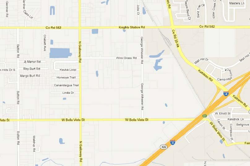
1 DRAINAGE REPORT FOR Creeks Crossing LOCATED AT: Galloway Road North Lakeland, Florida PREPARED FOR: Southern Homes/LM Properties OWNER: Heritage Investments of Polk, LLC PREPARED BY: SUBMITTED TO: Polk County SWFWMD PRINTED COPIES OF THIS DOCUMENT ARE NOT CONSIDERED SIGNED AND SEALED AND THE SHA-1 AUTHENTICATION CODE MUST BE VERIFIED ON ANY ELECTRONIC COPIES. THIS ITEM HAS BEEN ELECTRONICALLY SIGNED AND SEALED BY SANTOS MEDINA III, PE ON 06/30/16 USING A SHA-1 AUTHENTICATION CODE. Submitted: June 30, 2016 Santos Medina III, P.E. FL Reg #74539 FL CA #26247 Date
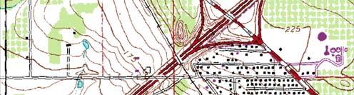
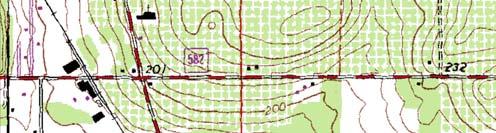
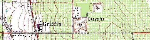
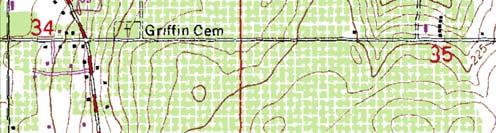
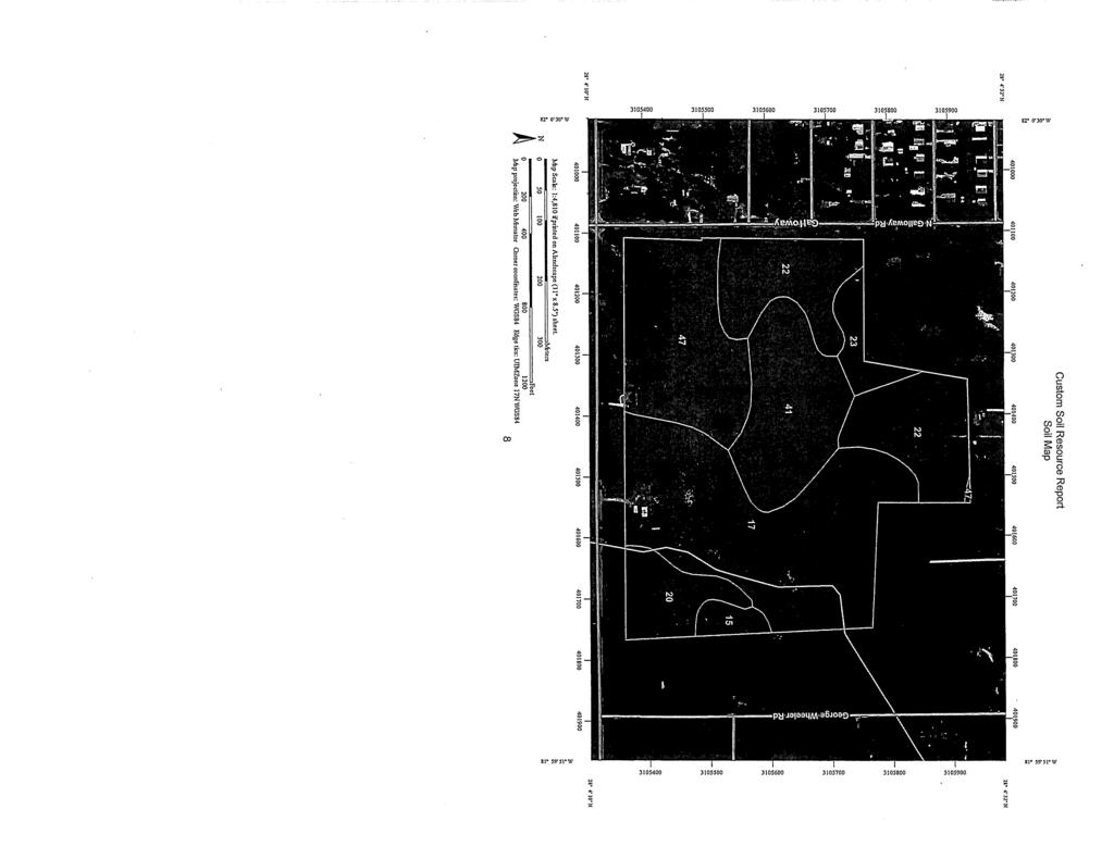
2 TABLE OF CONTENTS STORMWATER MANAGEMENT DESIGN SUMMARY...Chapter 1 Narrative References and Resources Floodplain Model Input Parameters Drainage Design Methodology Erosion Control Measures Operation and Maintenance Utilities EXHIBITS...Chapter 2 Map A Vicinity Map B USGS Quad Map C Site Map D Soils Map E Aerial Map F FEMA FIRM Map G Pre Development Basin Map Map H Post Development Basin Map SCS Data...Chapter 3 Curve Numbers WATER QUALITY...Chapter 4 Pond 100 WATER QUANTITY & FLOOD ROUTING...Chapter 5 ICPR Flood Routing STORM SEWER DESIGN...Chapter 6 SWALE DESIGN...Chapter 7 GEOTECH REPORT... Appendix A
3 CHAPTER 1 Stormwater Management Design Summary
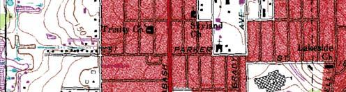
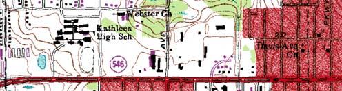
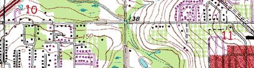
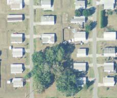
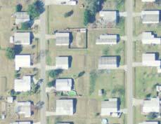
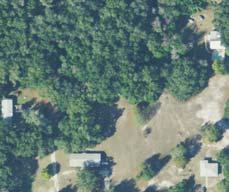
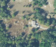
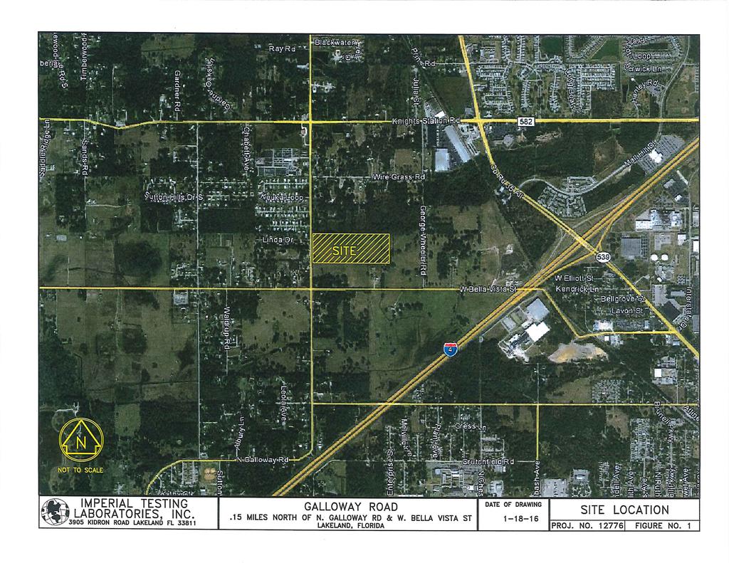
4 Narrative Southern Homes is proposing a 45 lot residential development with stormwater improvements in Polk County, FL in Section 03, Township 28 S, Range 23 E. The project s parcel id numbers are & Pickett Engineering, Inc. (PEI) has been retained to obtain a Level 2 Construction Permit from Polk County and a SWFWMD ERP for construction of a Stormwater Management system. This report contains the drainage design that supports the proposed improvements associated with the project. The system is designed to meet the rules and regulations concerning water quality and quantity as set forth by Polk County and the SWFWMD. The site is not part of an existing permit. The enclosed report provides detailed engineering calculations to aid the construction plans. Stormwater runoff of the impervious and pervious areas will be conveyed to one wet detention pond (Pond 100) for water quality and attenuation. References and Resources The following references and resources were used for this design: SWFWMD Applicant Handbook, Part III & IV State of Florida Department of Transportation Drainage Manual Polk County Land Development Code TR-55 Urban Hydrology for Small Watersheds Interconnected Channel and Pond Routing (ICPR) v3.10 with Perc Pack Floodplain According to the new FEMA Flood Zone Maps produced by Fema & Polk County, the site is not located within a 100-year flood zone.
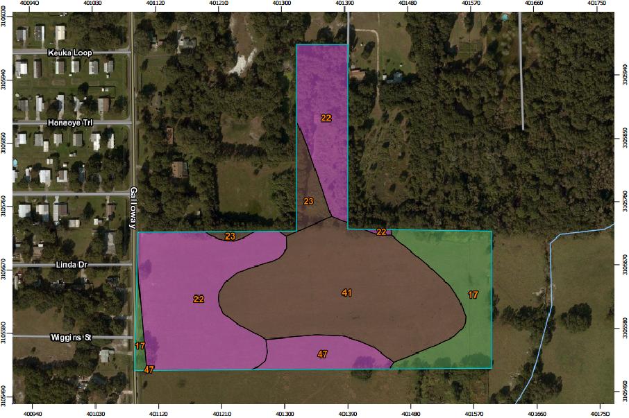
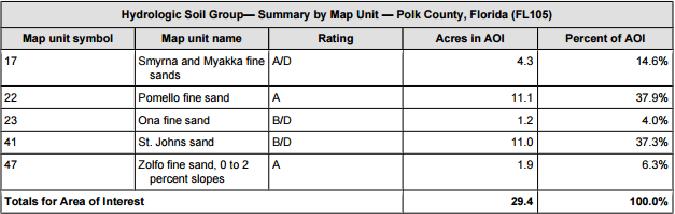
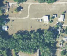
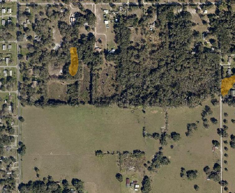
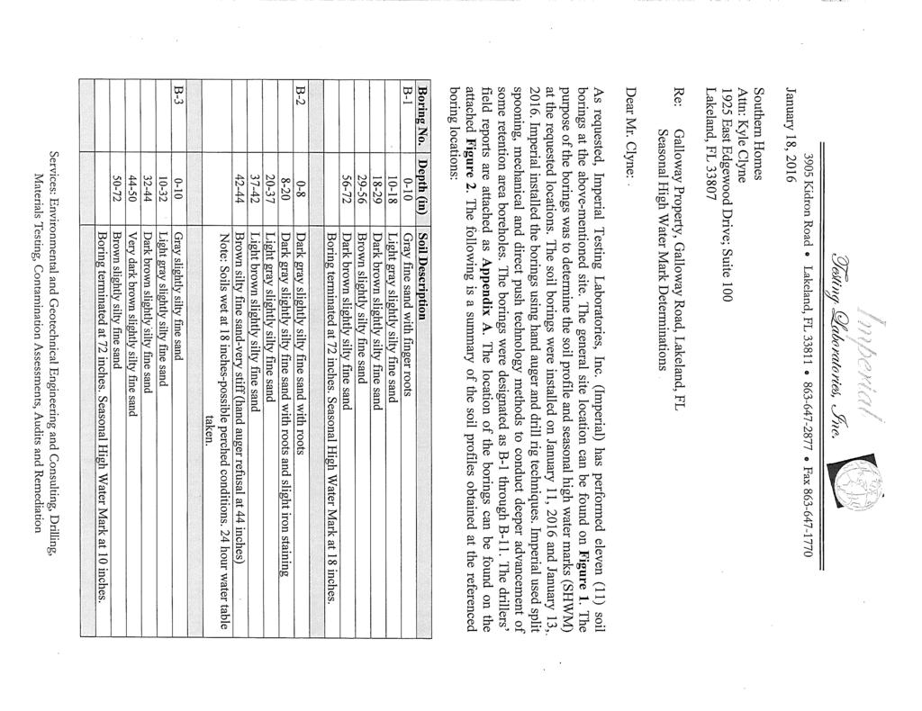
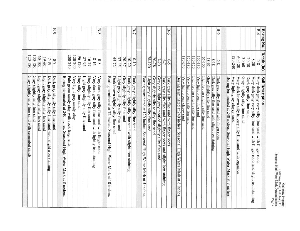
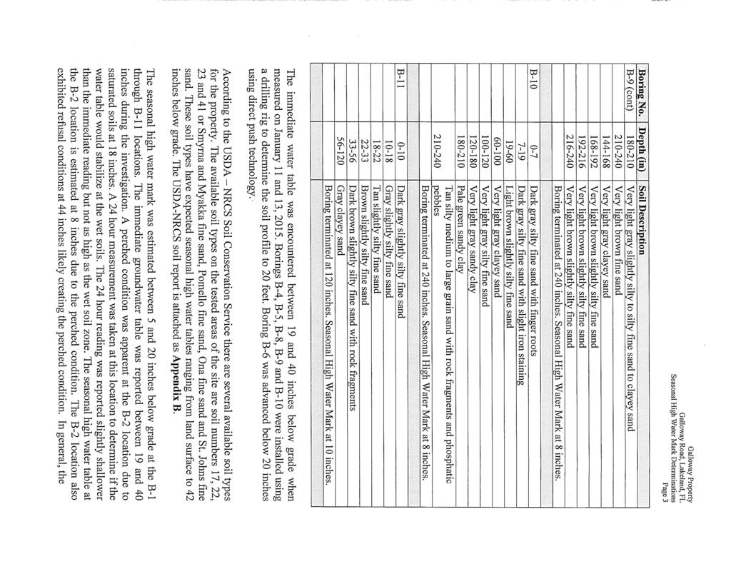
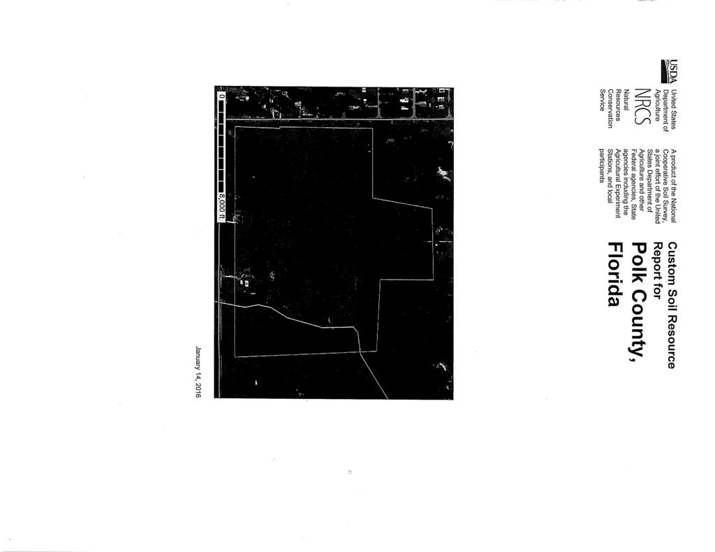
5 Model Input Parameters Groundwater Conditions The seasonal high water table elevations used in the storm water calculations were determined from soil boring data performed on site by Imperial Testing Laboratories, INC, located in Appendix A. The SHWT over the site was found to range from 5.0 inches to 18 inches below existing grade. Time of Concentration/Curve Numbers Composite curve numbers were created using procedures set forth in the TR-55 manual. Soil conditions were analyzed using the included Geotechnical Report, site observations, and the USDA web soil survey. Per the FDOT Drainage Manual, a minimum time of concentration of 10 minutes was used for either post development or pre development. See Chapter 3 for detailed Curve Number and Time of Concentration calculations. Drainage Basins The post-development drainage basins for the site were determined using the proposed grading and drainage plan. Pre-development basins were determined using 1-foot topographic survey information for the subject property. See Chapter 2 for detailed Basin Maps. Drainage Design Methodology Water Quality One hundred percent of all post development storm water runoff will be captured and treated in the wet retention Pond 100. A water treatment analysis was performed for the proposed impervious areas. See Chapter 4 for the water quality treatment volume model and more details. Water Quantity The 100 year/24 hour and the 25 year/24 hour design storm events were used to model the flood routing in accordance with SWFWMD and Polk County requirements. The post-development discharge rates and volume rates will be less than that of the pre-development; therefore, no off-site impacts will occur due to the proposed development. The project is located within an open basin. See Chapter 5 for the water quantity and flood routing model.
6 Storm Sewer The storm sewer system was designed utilizing a minimum diameter of 15 inches and a maximum diameter of 30 inches while setting pipe slopes at minimum grades to maintain reasonable velocities. The inlets and pipes will capture all storm water runoff on our site. The pipe capacity at minimum slopes exceeds the maximum inflows of the design storm. Please see Chapter 6 for more details. Erosion Control Measures All vegetative cover will be placed as soon as possible on all exposed land. These areas will be stabilized before any pause of construction. Silt fences will be installed along the perimeter of the project area to protect against adverse water quality impact during construction. Operation and Maintenance The developer will operate and maintain the stormwater management facilities as designed by the engineer. They will have the grassed areas mowed as necessary. Any debris or trash accumulated in the pond will be collected and disposed of properly. All SWM structures will be routinely inspected for accumulation of trash and sediments and be cleaned as required. Erosion in the ponds will be restored to the original condition promptly. Utilities Potable water will be provided by the City of Lakeland Water Department. No centralized sanitary sewer is located adjacent to the project; therefore, the proposed lots will use a septic tank and drain field.
7 CHAPTER 2 Exhibits
8


9
10
11

12
13
14
15
16
17 LEGEND GREEN TEXT BLUE TEXT RED TEXT NODE NAME BASIN NAME LINK NAME NODE LINE BASIN LINE LINK LINE 0' NORTH SCALE: 1" = 150' 75' 150' DESIGNED BY: CB DRAWN BY: DH CHECKED BY: SM NO. DATE APPROVED DESCRIPTION S-106 P-104 S-100 S-100 S-102 S-106 S-112 P-116 S-107 P-114 S-113 S-106 P-117 P-115 S-110 S-110 S-108 S-108 P-112 P-113 Pickett 150 SOUTH WOODLAWN AVENUE, BARTOW, FL PHONE: (863) FAX: (863) FLORIDA CERTIFICATE OF AUTHORIZATION (FLCA) #26247 S-101 P-105 S-101 S-103 S-103 P-105(1) P-109 P-110 P-111 S-104 S-104 S-105 POND 200 BASIN 200 S-109 P-107 S-111 SOUTHERN HOLDINGS OF POLK COUNTY, LLC CLIENT: S-109 CREEKS CROSSING PROJECT: BASIN 100 POND 100 PROJECT NO. POST DEVELOPMENT 1BASIN MAP SHEET 0 N GALLOWAY RD, LAKELAND FLORIDA OF 1
18 CHAPTER 3 SCS DATA
19 Curve Number Calculation Creeks Crossing, PEI Job #1422 A. Basin: A B. Total Area (ac): C. Curve Number: Cover Type Condition Soil Group CN Area Product Pervious Areas OpenSpace Good A OpenSpace Good D Impervious Areas Impervious Stormwater TOB A Impervious Building/Misc. A Impervious Pavement/Conc. A Total impervious area (excluding pond TOB) = Total contributing area (excluding pond TOB) = % DCIA for contributing area = 0.00% Sum: Weighted Curve Number: = Notes: * All information is referenced from TR-55, Urban Hydrology for Small Watersheds, Second Edition, June Poor condition (cover <50% or heavily grazed) 2 Fair condition (cover 50% to 75% or not heavily grazed) 3 Good condition (cover >75% or lightly grazed) 4 Roadway cover types include right-of-way 5 Open Space cover types include lawns, parks, golf courses, etc. 6 Pasture cover types include grasslands or ranges
20 Curve Number Calculation Creeks Crossing, PEI Job #1422 A. Basin: 100 (Overall) B. Total Area (ac): C. Curve Number: Cover Type Condition Soil Group CN Area Product Pervious Areas OpenSpace Good A OpenSpace Good D Impervious Areas Impervious Stormwater TOB A Impervious Building/Misc. A Impervious Pavement/Conc. A Total impervious area (excluding pond TOB) = Total contributing area (excluding pond TOB) = % DCIA for contributing area = 28.65% Sum: Weighted Curve Number: = Notes: * All information is referenced from TR-55, Urban Hydrology for Small Watersheds, Second Edition, June Poor condition (cover <50% or heavily grazed) 2 Fair condition (cover 50% to 75% or not heavily grazed) 3 Good condition (cover >75% or lightly grazed) 4 Roadway cover types include right-of-way 5 Open Space cover types include lawns, parks, golf courses, etc. 6 Pasture cover types include grasslands or ranges
21 CHAPTER 4 Water Quality
22 POND 100
23 Treatment Volumes - SWFWMD Creeks Crossing, PEI Job #1422 Basin Treatment Type Basin Area (ac) Treatment Volume (ac-ft) per Nutrient Loading WMD Basin Criteria OFW? Req'd Vol (ac-ft) Req'd Vol (cf) 100 (Overall) Wet Detention ,229 SWFWMD Basin Criteria Wet Detention Effluent Filtration Exfiltration On-line Retention Off-line Retention 1 " over basin 0.5 " over basin 0.5 " over basin 0.5 " over basin 0.5 " over basin Discharge to Outstanding Florida Waters: Treat 50% more than WMD basin criteria.
24 Retention Stage-Storage & Treatment Elevation Creeks Crossing, PEI Job #1422 Pond: 100 (Overall) Elevation Area (ft 2 ) Area (ac) Top , Control , STAGE DEPTH VOLUME VOLUME (ft) (ft) (ft 3 ) (ac-ft) , , , , , , , , , , , , , , , , , , , , , , , , , , , , ft 3 ac-ft Req. Treatment Vol: 95, Min Req. Treatment Elev: ft ft 3 ac-ft Provided Treatment Vol: 238, Weir Design Elev: ft Notes:
25 Pond: 100 A: Pool Volume Required Drainage area (A): ac Runoff coef (C): 0.59 Wet season rainfall depth (D): 31 in Length of wet season (WS): 121 days Residence time (R): 14 days PPV req = (A)(C)(D)(R) (WS)(12 in/ft) PPV req = ac-ft B: Pool Volume Provided Control elevation: control elevation: ft ac Littoral shelf elevation: littoral shelf: ft ac Stage 1: Bottom elevation: bottom: ac ft ac PPV provided = ac-ft Perm Pool Vol
26 A. SITE INFORMATION Site Ac. = Acres 22,220 = the minimum littoral shelf DER Elev. = Feet DER Area = 157,377 Sq. Ft. area in square feet. NWL = Feet NWL Area = 151,121 Sq. Ft. Runoff = 1.0 Inches (OFW?) 96,251 Cu.Ft. of treatent volume Head (h) = 0.49 Feet h = DER Elev. - (NWL + ½d) Required Volume = 95,229 Cu.Ft. or 2.19 Ac.Ft. B. VERTICAL CIRCULAR ORIFICE FLOW Q = C a (2 g h) ½ Diameter (d) = Orifice Area (a) = C Value = ½ Vol.Time = Total Time = 3.25 Inches Sq.Ft Coefficient of discharge Hours Hours Head Increm. Total Flow Delta Delta Cum. Elevation h (Ft.) h (Ft.) Q Q Avg. Volume Hours Hours sqrt(2 g h) , , , , , , , , , , , , , , , ,
27 , , , , , , , , , , , , , , , , , , , , , , , , ,400 C. 36 HOUR BLEEDDOWN CALCULATIONS Side Slopes = 4.0 TO 1 Centerline Surface Area DER = 157,377 SQ. FT. Orifice Treatment Surface Area NWL = 151,121 SQ. FT. Elevation Volume ,251
28 CHAPTER 5 Water Quantity & Flood Routing
29 Nodes A Stage/Area V Stage/Volume T Time/Stage M Manhole Basins O Overland Flow U SCS Unit CN S SBUH CN Y SCS Unit GA Z SBUH GA Links P Pipe W Weir C Channel D Drop Structure B Bridge R Rating Curve H Breach E Percolation F Filter X Exfil Trench T:A U:A A:100 U:100 W:O-100 W:W-100 T:OFFSITE Interconnected Channel and Pond Routing Model (ICPR) 2002 Streamline Technologies, Inc.
30 Max Warning Max Delta Max Surf Max Max Name Simulation Stage Stage Stage Area Inflow Outflow ft ft ft ft2 cfs cfs yr24hr yr24hr A 25yr24hr OFFSITE 25yr24hr Interconnected Channel and Pond Routing Model (ICPR) 2002 Streamline Technologies, Inc. Page 1 of 1
31 Simulation Node Group Time Stage Warning Surface Total Total Total Total Stage Area Inflow Outflow Vol In Vol Out hrs ft ft ft2 cfs cfs af af 25yr24hr A BASE yr24hr A BASE yr24hr A BASE yr24hr A BASE yr24hr A BASE yr24hr A BASE yr24hr A BASE yr24hr A BASE yr24hr A BASE yr24hr A BASE yr24hr A BASE yr24hr A BASE yr24hr A BASE yr24hr A BASE yr24hr A BASE yr24hr A BASE yr24hr A BASE yr24hr A BASE yr24hr A BASE yr24hr A BASE yr24hr A BASE yr24hr A BASE yr24hr A BASE yr24hr A BASE yr24hr A BASE yr24hr A BASE yr24hr A BASE yr24hr A BASE yr24hr A BASE yr24hr A BASE yr24hr A BASE yr24hr A BASE yr24hr A BASE yr24hr A BASE yr24hr A BASE yr24hr A BASE yr24hr A BASE yr24hr A BASE yr24hr A BASE yr24hr A BASE yr24hr A BASE yr24hr A BASE yr24hr A BASE yr24hr A BASE yr24hr A BASE yr24hr A BASE yr24hr A BASE yr24hr A BASE yr24hr A BASE yr24hr A BASE yr24hr A BASE yr24hr A BASE yr24hr A BASE yr24hr A BASE yr24hr A BASE yr24hr A BASE yr24hr A BASE yr24hr A BASE yr24hr A BASE yr24hr A BASE yr24hr A BASE yr24hr A BASE yr24hr A BASE yr24hr A BASE yr24hr A BASE yr24hr A BASE yr24hr A BASE yr24hr A BASE yr24hr A BASE yr24hr A BASE yr24hr A BASE yr24hr A BASE yr24hr A BASE yr24hr A BASE yr24hr A BASE yr24hr A BASE yr24hr A BASE yr24hr A BASE yr24hr A BASE yr24hr A BASE yr24hr A BASE yr24hr A BASE yr24hr A BASE yr24hr A BASE yr24hr A BASE yr24hr A BASE yr24hr A BASE yr24hr A BASE yr24hr A BASE yr24hr A BASE yr24hr A BASE yr24hr A BASE yr24hr A BASE yr24hr A BASE yr24hr A BASE yr24hr A BASE yr24hr A BASE yr24hr A BASE yr24hr A BASE yr24hr A BASE yr24hr A BASE yr24hr A BASE Interconnected Channel and Pond Routing Model (ICPR) 2002 Streamline Technologies, Inc. Page 1 of 4
32 Simulation Node Group Time Stage Warning Surface Total Total Total Total Stage Area Inflow Outflow Vol In Vol Out hrs ft ft ft2 cfs cfs af af 25yr24hr A BASE yr24hr A BASE yr24hr A BASE yr24hr A BASE yr24hr A BASE yr24hr A BASE yr24hr A BASE yr24hr A BASE yr24hr A BASE yr24hr A BASE yr24hr A BASE yr24hr A BASE yr24hr A BASE yr24hr A BASE yr24hr A BASE yr24hr A BASE yr24hr A BASE yr24hr A BASE yr24hr A BASE yr24hr A BASE yr24hr A BASE yr24hr A BASE yr24hr A BASE yr24hr A BASE yr24hr A BASE yr24hr A BASE yr24hr A BASE yr24hr A BASE yr24hr A BASE yr24hr A BASE yr24hr A BASE yr24hr A BASE yr24hr A BASE yr24hr A BASE yr24hr A BASE yr24hr A BASE yr24hr A BASE yr24hr A BASE yr24hr A BASE yr24hr A BASE yr24hr A BASE yr24hr A BASE yr24hr A BASE yr24hr A BASE yr24hr A BASE yr24hr A BASE yr24hr A BASE yr24hr A BASE yr24hr A BASE yr24hr A BASE yr24hr A BASE yr24hr A BASE yr24hr A BASE yr24hr A BASE yr24hr A BASE yr24hr A BASE yr24hr A BASE yr24hr A BASE yr24hr A BASE yr24hr A BASE yr24hr A BASE yr24hr A BASE yr24hr A BASE yr24hr A BASE yr24hr A BASE yr24hr A BASE yr24hr A BASE yr24hr A BASE yr24hr A BASE yr24hr A BASE yr24hr A BASE yr24hr A BASE yr24hr A BASE yr24hr A BASE yr24hr A BASE yr24hr A BASE yr24hr A BASE yr24hr A BASE yr24hr A BASE yr24hr OFFSITE BASE yr24hr OFFSITE BASE yr24hr OFFSITE BASE yr24hr OFFSITE BASE yr24hr OFFSITE BASE yr24hr OFFSITE BASE yr24hr OFFSITE BASE yr24hr OFFSITE BASE yr24hr OFFSITE BASE yr24hr OFFSITE BASE yr24hr OFFSITE BASE yr24hr OFFSITE BASE yr24hr OFFSITE BASE yr24hr OFFSITE BASE yr24hr OFFSITE BASE yr24hr OFFSITE BASE yr24hr OFFSITE BASE yr24hr OFFSITE BASE yr24hr OFFSITE BASE yr24hr OFFSITE BASE yr24hr OFFSITE BASE yr24hr OFFSITE BASE Interconnected Channel and Pond Routing Model (ICPR) 2002 Streamline Technologies, Inc. Page 2 of 4
33 Simulation Node Group Time Stage Warning Surface Total Total Total Total Stage Area Inflow Outflow Vol In Vol Out hrs ft ft ft2 cfs cfs af af 25yr24hr OFFSITE BASE yr24hr OFFSITE BASE yr24hr OFFSITE BASE yr24hr OFFSITE BASE yr24hr OFFSITE BASE yr24hr OFFSITE BASE yr24hr OFFSITE BASE yr24hr OFFSITE BASE yr24hr OFFSITE BASE yr24hr OFFSITE BASE yr24hr OFFSITE BASE yr24hr OFFSITE BASE yr24hr OFFSITE BASE yr24hr OFFSITE BASE yr24hr OFFSITE BASE yr24hr OFFSITE BASE yr24hr OFFSITE BASE yr24hr OFFSITE BASE yr24hr OFFSITE BASE yr24hr OFFSITE BASE yr24hr OFFSITE BASE yr24hr OFFSITE BASE yr24hr OFFSITE BASE yr24hr OFFSITE BASE yr24hr OFFSITE BASE yr24hr OFFSITE BASE yr24hr OFFSITE BASE yr24hr OFFSITE BASE yr24hr OFFSITE BASE yr24hr OFFSITE BASE yr24hr OFFSITE BASE yr24hr OFFSITE BASE yr24hr OFFSITE BASE yr24hr OFFSITE BASE yr24hr OFFSITE BASE yr24hr OFFSITE BASE yr24hr OFFSITE BASE yr24hr OFFSITE BASE yr24hr OFFSITE BASE yr24hr OFFSITE BASE yr24hr OFFSITE BASE yr24hr OFFSITE BASE yr24hr OFFSITE BASE yr24hr OFFSITE BASE yr24hr OFFSITE BASE yr24hr OFFSITE BASE yr24hr OFFSITE BASE yr24hr OFFSITE BASE yr24hr OFFSITE BASE yr24hr OFFSITE BASE yr24hr OFFSITE BASE yr24hr OFFSITE BASE yr24hr OFFSITE BASE yr24hr OFFSITE BASE yr24hr OFFSITE BASE yr24hr OFFSITE BASE yr24hr OFFSITE BASE yr24hr OFFSITE BASE yr24hr OFFSITE BASE yr24hr OFFSITE BASE yr24hr OFFSITE BASE yr24hr OFFSITE BASE yr24hr OFFSITE BASE yr24hr OFFSITE BASE yr24hr OFFSITE BASE yr24hr OFFSITE BASE yr24hr OFFSITE BASE yr24hr OFFSITE BASE yr24hr OFFSITE BASE yr24hr OFFSITE BASE yr24hr OFFSITE BASE yr24hr OFFSITE BASE yr24hr OFFSITE BASE yr24hr OFFSITE BASE yr24hr OFFSITE BASE yr24hr OFFSITE BASE yr24hr OFFSITE BASE yr24hr OFFSITE BASE yr24hr OFFSITE BASE yr24hr OFFSITE BASE yr24hr OFFSITE BASE yr24hr OFFSITE BASE yr24hr OFFSITE BASE yr24hr OFFSITE BASE yr24hr OFFSITE BASE yr24hr OFFSITE BASE yr24hr OFFSITE BASE yr24hr OFFSITE BASE yr24hr OFFSITE BASE yr24hr OFFSITE BASE yr24hr OFFSITE BASE yr24hr OFFSITE BASE yr24hr OFFSITE BASE yr24hr OFFSITE BASE yr24hr OFFSITE BASE yr24hr OFFSITE BASE yr24hr OFFSITE BASE yr24hr OFFSITE BASE yr24hr OFFSITE BASE yr24hr OFFSITE BASE yr24hr OFFSITE BASE yr24hr OFFSITE BASE Interconnected Channel and Pond Routing Model (ICPR) 2002 Streamline Technologies, Inc. Page 3 of 4
34 Simulation Node Group Time Stage Warning Surface Total Total Total Total Stage Area Inflow Outflow Vol In Vol Out hrs ft ft ft2 cfs cfs af af 25yr24hr OFFSITE BASE yr24hr OFFSITE BASE yr24hr OFFSITE BASE yr24hr OFFSITE BASE yr24hr OFFSITE BASE yr24hr OFFSITE BASE yr24hr OFFSITE BASE yr24hr OFFSITE BASE yr24hr OFFSITE BASE yr24hr OFFSITE BASE yr24hr OFFSITE BASE yr24hr OFFSITE BASE yr24hr OFFSITE BASE yr24hr OFFSITE BASE yr24hr OFFSITE BASE yr24hr OFFSITE BASE yr24hr OFFSITE BASE yr24hr OFFSITE BASE yr24hr OFFSITE BASE yr24hr OFFSITE BASE yr24hr OFFSITE BASE yr24hr OFFSITE BASE yr24hr OFFSITE BASE yr24hr OFFSITE BASE yr24hr OFFSITE BASE yr24hr OFFSITE BASE yr24hr OFFSITE BASE yr24hr OFFSITE BASE yr24hr OFFSITE BASE yr24hr OFFSITE BASE yr24hr OFFSITE BASE yr24hr OFFSITE BASE yr24hr OFFSITE BASE yr24hr OFFSITE BASE yr24hr OFFSITE BASE yr24hr OFFSITE BASE yr24hr OFFSITE BASE yr24hr OFFSITE BASE yr24hr OFFSITE BASE yr24hr OFFSITE BASE yr24hr OFFSITE BASE yr24hr OFFSITE BASE yr24hr OFFSITE BASE yr24hr OFFSITE BASE yr24hr OFFSITE BASE yr24hr OFFSITE BASE yr24hr OFFSITE BASE yr24hr OFFSITE BASE yr24hr OFFSITE BASE yr24hr OFFSITE BASE yr24hr OFFSITE BASE yr24hr OFFSITE BASE yr24hr OFFSITE BASE yr24hr OFFSITE BASE yr24hr OFFSITE BASE yr24hr OFFSITE BASE yr24hr OFFSITE BASE Interconnected Channel and Pond Routing Model (ICPR) 2002 Streamline Technologies, Inc. Page 4 of 4
35 ========================================================================================== ==== Basins ============================================================================== ========================================================================================== Name: 100 Node: 100 Status: Onsite Group: BASE Type: SCS Unit Hydrograph CN Unit Hydrograph: Uh256 Peaking Factor: Rainfall File: Storm Duration(hrs): 0.00 Rainfall Amount(in): Time of Conc(min): Area(ac): Time Shift(hrs): 0.00 Curve Number: Max Allowable Q(cfs): DCIA(%): Name: A Node: A Status: Onsite Group: BASE Type: SCS Unit Hydrograph CN Unit Hydrograph: Uh256 Peaking Factor: Rainfall File: Storm Duration(hrs): 0.00 Rainfall Amount(in): Time of Conc(min): Area(ac): Time Shift(hrs): 0.00 Curve Number: Max Allowable Q(cfs): DCIA(%): 0.00 ========================================================================================== ==== Nodes =============================================================================== ========================================================================================== Name: 100 Base Flow(cfs): Init Stage(ft): Group: BASE Warn Stage(ft): Type: Stage/Area Stage(ft) Area(ac) Name: A Base Flow(cfs): Init Stage(ft): Group: BASE Warn Stage(ft): Type: Time/Stage Time(hrs) Stage(ft) Name: OFFSITE Base Flow(cfs): Init Stage(ft): Group: BASE Warn Stage(ft): Type: Time/Stage Time(hrs) Stage(ft) ========================================================================================== ==== Weirs =============================================================================== ========================================================================================== Name: O-100 From Node: 100 Group: BASE To Node: OFFSITE Flow: Both Count: 1 Type: Vertical: Mavis Geometry: Circular Span(in): 3.25 Rise(in): 3.25 Invert(ft): Control Elevation(ft): Bottom Clip(in): Top Clip(in): Weir Discharge Coef: Orifice Discharge Coef: TABLE Name: W-100 From Node: 100 Group: BASE To Node: OFFSITE Flow: Both Count: 1 Type: Vertical: Mavis Geometry: Trapezoidal Bottom Width(ft): 6.00 Left Side Slope(h/v): 4.00 Right Side Slope(h/v): 4.00 Invert(ft): Control Elevation(ft): Struct Opening Dim(ft): Bottom Clip(ft): Top Clip(ft): TABLE Interconnected Channel and Pond Routing Model (ICPR) 2002 Streamline Technologies, Inc. Page 1 of 2
36 Weir Discharge Coef: Orifice Discharge Coef: ========================================================================================== ==== Hydrology Simulations =============================================================== ========================================================================================== Name: 100yr24hr Filename: X:\Engineering\PEI Standards\ICPR\100yr24hr.R32 Override Defaults: Yes Storm Duration(hrs): Rainfall File: Flmod Rainfall Amount(in): Time(hrs) Print Inc(min) Name: 25yr24hr Filename: X:\Engineering\PEI Standards\ICPR\25yr24hr.R32 Override Defaults: Yes Storm Duration(hrs): Rainfall File: Flmod Rainfall Amount(in): 7.00 Time(hrs) Print Inc(min) ========================================================================================== ==== Routing Simulations ================================================================= ========================================================================================== Name: 100yr24hr Hydrology Sim: 100yr24hr Filename: X:\Engineering\PEI Standards\ICPR\100yr24hr.I32 Execute: Yes Restart: No Patch: No Alternative: No Max Delta Z(ft): 1.00 Delta Z Factor: Time Step Optimizer: Start Time(hrs): End Time(hrs): Min Calc Time(sec): Max Calc Time(sec): Boundary Stages: Boundary Flows: Time(hrs) Print Inc(min) Group Run BASE Yes Name: 25yr24hr Hydrology Sim: 25yr24hr Filename: X:\Engineering\PEI Standards\ICPR\25yr24hr.I32 Execute: Yes Restart: No Patch: No Alternative: No Max Delta Z(ft): 1.00 Delta Z Factor: Time Step Optimizer: Start Time(hrs): End Time(hrs): Min Calc Time(sec): Max Calc Time(sec): Boundary Stages: Boundary Flows: Time(hrs) Print Inc(min) Group Run BASE Yes Interconnected Channel and Pond Routing Model (ICPR) 2002 Streamline Technologies, Inc. Page 2 of 2
37 CHAPTER 6 Storm Sewer Design
38 Curve Number Calculation Creeks Crossing, PEI Job #1422 A. Basin: S-100 B. Total Area (ac): C. Curve Number: Cover Type Condition Soil Group CN Area Product Pervious Areas OpenSpace Good A Impervious Areas Impervious Stormwater TOB A Impervious Building/Misc. A Impervious Pavement/Conc. A Total impervious area (excluding pond TOB) = Total contributing area (excluding pond TOB) = % DCIA for contributing area = 69.77% Sum: Weighted Curve Number: = Notes: * All information is referenced from TR-55, Urban Hydrology for Small Watersheds, Second Edition, June Poor condition (cover <50% or heavily grazed) 2 Fair condition (cover 50% to 75% or not heavily grazed) 3 Good condition (cover >75% or lightly grazed) 4 Roadway cover types include right-of-way 5 Open Space cover types include lawns, parks, golf courses, etc. 6 Pasture cover types include grasslands or ranges
39 Curve Number Calculation Creeks Crossing, PEI Job #1422 A. Basin: S-101 B. Total Area (ac): C. Curve Number: Cover Type Condition Soil Group CN Area Product Pervious Areas OpenSpace Good A Impervious Areas Impervious Stormwater TOB A Impervious Building/Misc. A Impervious Pavement/Conc. A Total impervious area (excluding pond TOB) = Total contributing area (excluding pond TOB) = % DCIA for contributing area = 74.36% Sum: Weighted Curve Number: = Notes: * All information is referenced from TR-55, Urban Hydrology for Small Watersheds, Second Edition, June Poor condition (cover <50% or heavily grazed) 2 Fair condition (cover 50% to 75% or not heavily grazed) 3 Good condition (cover >75% or lightly grazed) 4 Roadway cover types include right-of-way 5 Open Space cover types include lawns, parks, golf courses, etc. 6 Pasture cover types include grasslands or ranges
40 Curve Number Calculation Creeks Crossing, PEI Job #1422 A. Basin: S-103 B. Total Area (ac): C. Curve Number: Cover Type Condition Soil Group CN Area Product Pervious Areas OpenSpace Good A Impervious Areas Impervious Stormwater TOB A Impervious Building/Misc. A Impervious Pavement/Conc. A Total impervious area (excluding pond TOB) = Total contributing area (excluding pond TOB) = % DCIA for contributing area = 69.61% Sum: Weighted Curve Number: = Notes: * All information is referenced from TR-55, Urban Hydrology for Small Watersheds, Second Edition, June Poor condition (cover <50% or heavily grazed) 2 Fair condition (cover 50% to 75% or not heavily grazed) 3 Good condition (cover >75% or lightly grazed) 4 Roadway cover types include right-of-way 5 Open Space cover types include lawns, parks, golf courses, etc. 6 Pasture cover types include grasslands or ranges
41 Curve Number Calculation Creeks Crossing, PEI Job #1422 A. Basin: S-104 B. Total Area (ac): C. Curve Number: Cover Type Condition Soil Group CN Area Product Pervious Areas OpenSpace Good A Impervious Areas Impervious Stormwater TOB A Impervious Building/Misc. A Impervious Pavement/Conc. A Total impervious area (excluding pond TOB) = Total contributing area (excluding pond TOB) = % DCIA for contributing area = 69.19% Sum: Weighted Curve Number: = Notes: * All information is referenced from TR-55, Urban Hydrology for Small Watersheds, Second Edition, June Poor condition (cover <50% or heavily grazed) 2 Fair condition (cover 50% to 75% or not heavily grazed) 3 Good condition (cover >75% or lightly grazed) 4 Roadway cover types include right-of-way 5 Open Space cover types include lawns, parks, golf courses, etc. 6 Pasture cover types include grasslands or ranges
42 Curve Number Calculation Creeks Crossing, PEI Job #1422 A. Basin: S-106 B. Total Area (ac): C. Curve Number: Cover Type Condition Soil Group CN Area Product Pervious Areas OpenSpace Good A OpenSpace Good D Impervious Areas Impervious Stormwater TOB A Impervious Building/Misc. A Impervious Pavement/Conc. A Total impervious area (excluding pond TOB) = Total contributing area (excluding pond TOB) = % DCIA for contributing area = 20.92% Sum: Weighted Curve Number: = Notes: * All information is referenced from TR-55, Urban Hydrology for Small Watersheds, Second Edition, June Poor condition (cover <50% or heavily grazed) 2 Fair condition (cover 50% to 75% or not heavily grazed) 3 Good condition (cover >75% or lightly grazed) 4 Roadway cover types include right-of-way 5 Open Space cover types include lawns, parks, golf courses, etc. 6 Pasture cover types include grasslands or ranges
43 Curve Number Calculation Creeks Crossing, PEI Job #1422 A. Basin: S-108 B. Total Area (ac): C. Curve Number: Cover Type Condition Soil Group CN Area Product Pervious Areas OpenSpace Good A OpenSpace Good D Impervious Areas Impervious Stormwater TOB A Impervious Building/Misc. A Impervious Pavement/Conc. A Total impervious area (excluding pond TOB) = Total contributing area (excluding pond TOB) = % DCIA for contributing area = 41.67% Sum: Weighted Curve Number: = Notes: * All information is referenced from TR-55, Urban Hydrology for Small Watersheds, Second Edition, June Poor condition (cover <50% or heavily grazed) 2 Fair condition (cover 50% to 75% or not heavily grazed) 3 Good condition (cover >75% or lightly grazed) 4 Roadway cover types include right-of-way 5 Open Space cover types include lawns, parks, golf courses, etc. 6 Pasture cover types include grasslands or ranges
44 Curve Number Calculation Creeks Crossing, PEI Job #1422 A. Basin: S-109 B. Total Area (ac): C. Curve Number: Cover Type Condition Soil Group CN Area Product Pervious Areas OpenSpace Good A OpenSpace Good D Impervious Areas Impervious Stormwater TOB A Impervious Building/Misc. A Impervious Pavement/Conc. A Total impervious area (excluding pond TOB) = Total contributing area (excluding pond TOB) = % DCIA for contributing area = 61.52% Sum: Weighted Curve Number: = Notes: * All information is referenced from TR-55, Urban Hydrology for Small Watersheds, Second Edition, June Poor condition (cover <50% or heavily grazed) 2 Fair condition (cover 50% to 75% or not heavily grazed) 3 Good condition (cover >75% or lightly grazed) 4 Roadway cover types include right-of-way 5 Open Space cover types include lawns, parks, golf courses, etc. 6 Pasture cover types include grasslands or ranges
45 Curve Number Calculation Creeks Crossing, PEI Job #1422 A. Basin: S-110 B. Total Area (ac): C. Curve Number: Cover Type Condition Soil Group CN Area Product Pervious Areas OpenSpace Good A OpenSpace Good D Impervious Areas Impervious Stormwater TOB A Impervious Building/Misc. A Impervious Pavement/Conc. A Total impervious area (excluding pond TOB) = Total contributing area (excluding pond TOB) = % DCIA for contributing area = 43.37% Sum: Weighted Curve Number: = Notes: * All information is referenced from TR-55, Urban Hydrology for Small Watersheds, Second Edition, June Poor condition (cover <50% or heavily grazed) 2 Fair condition (cover 50% to 75% or not heavily grazed) 3 Good condition (cover >75% or lightly grazed) 4 Roadway cover types include right-of-way 5 Open Space cover types include lawns, parks, golf courses, etc. 6 Pasture cover types include grasslands or ranges
46 Curve Number Calculation Creeks Crossing, PEI Job #1422 A. Basin: 200 B. Total Area (ac): C. Curve Number: Cover Type Condition Soil Group CN Area Product Pervious Areas OpenSpace Good A OpenSpace Good D Impervious Areas Impervious Stormwater TOB A Impervious Building/Misc. A Impervious Pavement/Conc. A Total impervious area (excluding pond TOB) = Total contributing area (excluding pond TOB) = % DCIA for contributing area = 22.58% Sum: Weighted Curve Number: = Notes: * All information is referenced from TR-55, Urban Hydrology for Small Watersheds, Second Edition, June Poor condition (cover <50% or heavily grazed) 2 Fair condition (cover 50% to 75% or not heavily grazed) 3 Good condition (cover >75% or lightly grazed) 4 Roadway cover types include right-of-way 5 Open Space cover types include lawns, parks, golf courses, etc. 6 Pasture cover types include grasslands or ranges
47 Nodes A Stage/Area V Stage/Volume T Time/Stage M Manhole Basins O Overland Flow U SCS Unit CN S SBUH CN Y SCS Unit GA Z SBUH GA P: P-104 A: S-100 U: S-100 A: S-101 A: S-110 U: S-110 A: S-106 U: S-106 P: P-114 Links P Pipe W Weir C Channel D Drop Structure B Bridge R Rating Curve H Breach E Percolation F Filter X Exfil Trench P: P-105 P:P-105 (1) U: S-101 A: S-102 P: P-112 A: S-108 U: S-108 A: S-107 P: P-115 A: S-103 P: P-109 U: S-103 P: P-113 A: S-104 U: S-104 A: S-109 P: P-110 U: S-109 A:200 U:200 P: P-107 W: W-200 T: S-111 T:100 Interconnected Channel and Pond Routing Model (ICPR) 2002 Streamline Technologies, Inc.
48 Max Warning Max Delta Max Surf Max Max Name Simulation Stage Stage Stage Area Inflow Outflow ft ft ft ft2 cfs cfs yr24hr S yr24hr S yr24hr S yr24hr S yr24hr S yr24hr S yr24hr S yr24hr S yr24hr S yr24hr S yr24hr Interconnected Channel and Pond Routing Model (ICPR) 2002 Streamline Technologies, Inc. Page 1 of 1
49 ========================================================================================== ==== Basins ============================================================================== ========================================================================================== Name: 200 Node: 200 Status: Onsite Group: BASE Type: SCS Unit Hydrograph CN Unit Hydrograph: Uh256 Peaking Factor: Rainfall File: Storm Duration(hrs): 0.00 Rainfall Amount(in): Time of Conc(min): Area(ac): Time Shift(hrs): 0.00 Curve Number: Max Allowable Q(cfs): DCIA(%): Name: S-100 Node: S-100 Status: Onsite Group: BASE Type: SCS Unit Hydrograph CN Unit Hydrograph: Uh256 Peaking Factor: Rainfall File: Storm Duration(hrs): 0.00 Rainfall Amount(in): Time of Conc(min): Area(ac): Time Shift(hrs): 0.00 Curve Number: Max Allowable Q(cfs): DCIA(%): Name: S-101 Node: S-101 Status: Onsite Group: BASE Type: SCS Unit Hydrograph CN Unit Hydrograph: Uh256 Peaking Factor: Rainfall File: Storm Duration(hrs): 0.00 Rainfall Amount(in): Time of Conc(min): Area(ac): Time Shift(hrs): 0.00 Curve Number: Max Allowable Q(cfs): DCIA(%): Name: S-103 Node: S-103 Status: Onsite Group: BASE Type: SCS Unit Hydrograph CN Unit Hydrograph: Uh256 Peaking Factor: Rainfall File: Storm Duration(hrs): 0.00 Rainfall Amount(in): Time of Conc(min): Area(ac): Time Shift(hrs): 0.00 Curve Number: Max Allowable Q(cfs): DCIA(%): Name: S-104 Node: S-104 Status: Onsite Group: BASE Type: SCS Unit Hydrograph CN Unit Hydrograph: Uh256 Peaking Factor: Rainfall File: Storm Duration(hrs): 0.00 Rainfall Amount(in): Time of Conc(min): Area(ac): Time Shift(hrs): 0.00 Curve Number: Max Allowable Q(cfs): DCIA(%): Name: S-106 Node: S-106 Status: Onsite Group: BASE Type: SCS Unit Hydrograph CN Unit Hydrograph: Uh256 Peaking Factor: Rainfall File: Storm Duration(hrs): 0.00 Rainfall Amount(in): Time of Conc(min): Area(ac): Time Shift(hrs): 0.00 Curve Number: Max Allowable Q(cfs): DCIA(%): Name: S-108 Node: S-108 Status: Onsite Group: BASE Type: SCS Unit Hydrograph CN Unit Hydrograph: Uh256 Peaking Factor: Rainfall File: Storm Duration(hrs): 0.00 Rainfall Amount(in): Time of Conc(min): Area(ac): Time Shift(hrs): 0.00 Curve Number: Max Allowable Q(cfs): DCIA(%): Name: S-109 Node: S-109 Status: Onsite Group: BASE Type: SCS Unit Hydrograph CN Unit Hydrograph: Uh256 Peaking Factor: Rainfall File: Storm Duration(hrs): 0.00 Rainfall Amount(in): Time of Conc(min): Area(ac): Time Shift(hrs): 0.00 Curve Number: Max Allowable Q(cfs): DCIA(%): 0.00 Interconnected Channel and Pond Routing Model (ICPR) 2002 Streamline Technologies, Inc. Page 1 of 6
50 Name: S-110 Node: S-110 Status: Onsite Group: BASE Type: SCS Unit Hydrograph CN Unit Hydrograph: Uh256 Peaking Factor: Rainfall File: Storm Duration(hrs): 0.00 Rainfall Amount(in): Time of Conc(min): Area(ac): Time Shift(hrs): 0.00 Curve Number: Max Allowable Q(cfs): DCIA(%): 0.00 ========================================================================================== ==== Nodes =============================================================================== ========================================================================================== Name: 100 Base Flow(cfs): Init Stage(ft): Group: BASE Warn Stage(ft): Type: Time/Stage We used a tailwater condition of '. We feel this is conservative as it represents the top of Pond 100. Time(hrs) Stage(ft) Name: 200 Base Flow(cfs): Init Stage(ft): Group: BASE Warn Stage(ft): Type: Stage/Area Stage(ft) Area(ac) Name: S-100 Base Flow(cfs): Init Stage(ft): Group: BASE Warn Stage(ft): Type: Stage/Area Stage(ft) Area(ac) Name: S-101 Base Flow(cfs): Init Stage(ft): Group: BASE Warn Stage(ft): Type: Stage/Area Stage(ft) Area(ac) Name: S-102 Base Flow(cfs): Init Stage(ft): Group: BASE Warn Stage(ft): Type: Stage/Area Stage(ft) Area(ac) Name: S-103 Base Flow(cfs): Init Stage(ft): Group: BASE Warn Stage(ft): Type: Stage/Area Stage(ft) Area(ac) Name: S-104 Base Flow(cfs): Init Stage(ft): Group: BASE Warn Stage(ft): Type: Stage/Area Stage(ft) Area(ac) Name: S-106 Base Flow(cfs): Init Stage(ft): Interconnected Channel and Pond Routing Model (ICPR) 2002 Streamline Technologies, Inc. Page 2 of 6
51 Group: BASE Warn Stage(ft): Type: Stage/Area Stage(ft) Area(ac) Name: S-107 Base Flow(cfs): Init Stage(ft): Group: BASE Warn Stage(ft): Type: Stage/Area Stage(ft) Area(ac) Name: S-108 Base Flow(cfs): Init Stage(ft): Group: BASE Warn Stage(ft): Type: Stage/Area Stage(ft) Area(ac) Name: S-109 Base Flow(cfs): Init Stage(ft): Group: BASE Warn Stage(ft): Type: Stage/Area Stage(ft) Area(ac) Name: S-110 Base Flow(cfs): Init Stage(ft): Group: BASE Warn Stage(ft): Type: Stage/Area Stage(ft) Area(ac) Name: S-111 Base Flow(cfs): Init Stage(ft): Group: BASE Warn Stage(ft): Type: Time/Stage The tailwater elevation of ' represent the top of the discharge swale leading to Pond 100. Time(hrs) Stage(ft) ========================================================================================== ==== Pipes =============================================================================== ========================================================================================== Name: P-104 From Node: S-100 Length(ft): Group: BASE To Node: S-101 Count: 1 Friction Equation: Automatic UPSTREAM DOWNSTREAM Solution Algorithm: Most Restrictive Geometry: Circular Circular Flow: Both Span(in): Entrance Loss Coef: 0.00 Rise(in): Exit Loss Coef: 1.00 Invert(ft): Bend Loss Coef: 0.00 Manning's N: Outlet Ctrl Spec: Use dc or tw Top Clip(in): Inlet Ctrl Spec: Use dc Bot Clip(in): Stabilizer Option: None Upstream FHWA Inlet Edge Description: Circular Concrete: Square edge w/ headwall Downstream FHWA Inlet Edge Description: Circular Concrete: Square edge w/ headwall Name: P-105 From Node: S-101 Length(ft): Group: BASE To Node: S-102 Count: 1 Friction Equation: Automatic UPSTREAM DOWNSTREAM Solution Algorithm: Most Restrictive Geometry: Circular Circular Flow: Both Span(in): Entrance Loss Coef: 0.00 Rise(in): Exit Loss Coef: 1.00 Invert(ft): Bend Loss Coef: 0.00 Interconnected Channel and Pond Routing Model (ICPR) 2002 Streamline Technologies, Inc. Page 3 of 6
52 Manning's N: Outlet Ctrl Spec: Use dc or tw Top Clip(in): Inlet Ctrl Spec: Use dc Bot Clip(in): Stabilizer Option: None Upstream FHWA Inlet Edge Description: Circular Concrete: Square edge w/ headwall Downstream FHWA Inlet Edge Description: Circular Concrete: Square edge w/ headwall Name: P-105 (1) From Node: S-102 Length(ft): Group: BASE To Node: S-103 Count: 1 Friction Equation: Automatic UPSTREAM DOWNSTREAM Solution Algorithm: Most Restrictive Geometry: Circular Circular Flow: Both Span(in): Entrance Loss Coef: 0.00 Rise(in): Exit Loss Coef: 1.00 Invert(ft): Bend Loss Coef: 0.00 Manning's N: Outlet Ctrl Spec: Use dc or tw Top Clip(in): Inlet Ctrl Spec: Use dc Bot Clip(in): Stabilizer Option: None Upstream FHWA Inlet Edge Description: Circular Concrete: Square edge w/ headwall Downstream FHWA Inlet Edge Description: Circular Concrete: Square edge w/ headwall Name: P-107 From Node: S-109 Length(ft): Group: BASE To Node: S-111 Count: 1 Friction Equation: Automatic UPSTREAM DOWNSTREAM Solution Algorithm: Most Restrictive Geometry: Circular Circular Flow: Both Span(in): Entrance Loss Coef: 0.00 Rise(in): Exit Loss Coef: 1.00 Invert(ft): Bend Loss Coef: 0.00 Manning's N: Outlet Ctrl Spec: Use dc or tw Top Clip(in): Inlet Ctrl Spec: Use dc Bot Clip(in): Stabilizer Option: None Upstream FHWA Inlet Edge Description: Circular Concrete: Square edge w/ headwall Downstream FHWA Inlet Edge Description: Circular Concrete: Square edge w/ headwall Name: P-109 From Node: S-103 Length(ft): Group: BASE To Node: S-104 Count: 1 Friction Equation: Automatic UPSTREAM DOWNSTREAM Solution Algorithm: Most Restrictive Geometry: Circular Circular Flow: Both Span(in): Entrance Loss Coef: 0.00 Rise(in): Exit Loss Coef: 1.00 Invert(ft): Bend Loss Coef: 0.00 Manning's N: Outlet Ctrl Spec: Use dc or tw Top Clip(in): Inlet Ctrl Spec: Use dc Bot Clip(in): Stabilizer Option: None Upstream FHWA Inlet Edge Description: Circular Concrete: Square edge w/ headwall Downstream FHWA Inlet Edge Description: Circular Concrete: Square edge w/ headwall Name: P-110 From Node: S-104 Length(ft): Group: BASE To Node: 200 Count: 1 Friction Equation: Automatic UPSTREAM DOWNSTREAM Solution Algorithm: Most Restrictive Geometry: Circular Circular Flow: Both Span(in): Entrance Loss Coef: 0.00 Rise(in): Exit Loss Coef: 1.00 Invert(ft): Bend Loss Coef: 0.00 Manning's N: Outlet Ctrl Spec: Use dc or tw Top Clip(in): Inlet Ctrl Spec: Use dc Bot Clip(in): Stabilizer Option: None Upstream FHWA Inlet Edge Description: Circular Concrete: Square edge w/ headwall Downstream FHWA Inlet Edge Description: Circular Concrete: Square edge w/ headwall Interconnected Channel and Pond Routing Model (ICPR) 2002 Streamline Technologies, Inc. Page 4 of 6
53 Name: P-112 From Node: S-110 Length(ft): Group: BASE To Node: S-108 Count: 1 Friction Equation: Automatic UPSTREAM DOWNSTREAM Solution Algorithm: Most Restrictive Geometry: Circular Circular Flow: Both Span(in): Entrance Loss Coef: 0.00 Rise(in): Exit Loss Coef: 1.00 Invert(ft): Bend Loss Coef: 0.00 Manning's N: Outlet Ctrl Spec: Use dc or tw Top Clip(in): Inlet Ctrl Spec: Use dc Bot Clip(in): Stabilizer Option: None Upstream FHWA Inlet Edge Description: Circular Concrete: Square edge w/ headwall Downstream FHWA Inlet Edge Description: Circular Concrete: Square edge w/ headwall Name: P-113 From Node: S-108 Length(ft): Group: BASE To Node: S-109 Count: 1 Friction Equation: Automatic UPSTREAM DOWNSTREAM Solution Algorithm: Most Restrictive Geometry: Circular Circular Flow: Both Span(in): Entrance Loss Coef: 0.00 Rise(in): Exit Loss Coef: 1.00 Invert(ft): Bend Loss Coef: 0.00 Manning's N: Outlet Ctrl Spec: Use dc or tw Top Clip(in): Inlet Ctrl Spec: Use dc Bot Clip(in): Stabilizer Option: None Upstream FHWA Inlet Edge Description: Circular Concrete: Square edge w/ headwall Downstream FHWA Inlet Edge Description: Circular Concrete: Square edge w/ headwall Name: P-114 From Node: S-106 Length(ft): Group: BASE To Node: S-107 Count: 1 Friction Equation: Automatic UPSTREAM DOWNSTREAM Solution Algorithm: Most Restrictive Geometry: Circular Circular Flow: Both Span(in): Entrance Loss Coef: 0.00 Rise(in): Exit Loss Coef: 1.00 Invert(ft): Bend Loss Coef: 0.00 Manning's N: Outlet Ctrl Spec: Use dc or tw Top Clip(in): Inlet Ctrl Spec: Use dc Bot Clip(in): Stabilizer Option: None Upstream FHWA Inlet Edge Description: Circular Concrete: Square edge w/ headwall Downstream FHWA Inlet Edge Description: Circular Concrete: Square edge w/ headwall Name: P-115 From Node: S-107 Length(ft): Group: BASE To Node: S-108 Count: 1 Friction Equation: Automatic UPSTREAM DOWNSTREAM Solution Algorithm: Most Restrictive Geometry: Circular Circular Flow: Both Span(in): Entrance Loss Coef: 0.00 Rise(in): Exit Loss Coef: 1.00 Invert(ft): Bend Loss Coef: 0.00 Manning's N: Outlet Ctrl Spec: Use dc or tw Top Clip(in): Inlet Ctrl Spec: Use dc Bot Clip(in): Stabilizer Option: None Upstream FHWA Inlet Edge Description: Circular Concrete: Square edge w/ headwall Downstream FHWA Inlet Edge Description: Circular Concrete: Square edge w/ headwall ========================================================================================== ==== Weirs =============================================================================== ========================================================================================== Name: W-200 From Node: 200 Group: BASE To Node: 100 Flow: Both Count: 1 Type: Vertical: Mavis Geometry: Trapezoidal Bottom Width(ft): 2.00 Left Side Slope(h/v): 4.00 Right Side Slope(h/v): 4.00 Interconnected Channel and Pond Routing Model (ICPR) 2002 Streamline Technologies, Inc. Page 5 of 6
54 Invert(ft): Control Elevation(ft): Struct Opening Dim(ft): Bottom Clip(ft): Top Clip(ft): Weir Discharge Coef: Orifice Discharge Coef: TABLE ========================================================================================== ==== Hydrology Simulations =============================================================== ========================================================================================== Name: 100yr24hr Filename: X:\Engineering\PEI Standards\ICPR\100yr24hr.R32 Override Defaults: Yes Storm Duration(hrs): Rainfall File: Flmod Rainfall Amount(in): Time(hrs) Print Inc(min) Name: 25yr24hr Filename: X:\Engineering\PEI Standards\ICPR\25yr24hr.R32 Override Defaults: Yes Storm Duration(hrs): Rainfall File: Flmod Rainfall Amount(in): 7.00 Time(hrs) Print Inc(min) ========================================================================================== ==== Routing Simulations ================================================================= ========================================================================================== Name: 100yr24hr Hydrology Sim: 100yr24hr Filename: X:\Engineering\PEI Standards\ICPR\100yr24hr.I32 Execute: No Restart: No Patch: No Alternative: No Max Delta Z(ft): 1.00 Delta Z Factor: Time Step Optimizer: Start Time(hrs): End Time(hrs): Min Calc Time(sec): Max Calc Time(sec): Boundary Stages: Boundary Flows: Time(hrs) Print Inc(min) Group Run BASE Yes Name: 25yr24hr Hydrology Sim: 25yr24hr Filename: X:\Engineering\PEI Standards\ICPR\25yr24hr.I32 Execute: Yes Restart: No Patch: No Alternative: No Max Delta Z(ft): 1.00 Delta Z Factor: Time Step Optimizer: Start Time(hrs): End Time(hrs): Min Calc Time(sec): Max Calc Time(sec): Boundary Stages: Boundary Flows: Time(hrs) Print Inc(min) Group Run BASE Yes Interconnected Channel and Pond Routing Model (ICPR) 2002 Streamline Technologies, Inc. Page 6 of 6
55 CHAPTER 7 Swale Design
56 < < < < < < < < < < < < < < < < < < < < < SWALE 300 SWALE 300 BASIN < < < < < < < < < < < < < < < SWALE 400 SWALE 400 BASIN AWE AWE AWE AWE AWE AWE AWE AWE AWE AWE AWE AWE AWE AWE GREEN TEXT BLUE TEXT RED TEXT AWE AWE LEGEND AWE AWE AWE AWE AWE AWE AWE AWE AWE AWE AWE AWE AWE AWE AWE AWE AWE AWE AWE AWE AWE AWE AWE AWE AWE AWE AWE AWE AWE AWE AWE AWE SWALE 200 BASIN AWE < < NODE NAME BASIN NAME LINK NAME NODE LINE BASIN LINE LINK LINE 0' NORTH SCALE: 1" = 150' 75' 150' NO. DATE APPROVED DESCRIPTION DESIGNED BY: CB DRAWN BY: DH Pickett CHECKED BY: SM 150 SOUTH WOODLAWN AVENUE, BARTOW, FL PHONE: (863) FAX: (863) FLORIDA CERTIFICATE OF AUTHORIZATION (FLCA) #26247 SWALE 200 < < < < < < < < SWALE 100 BASIN SWALE 100 < < < < < < < < SOUTHERN HOLDINGS OF POLK COUNTY, LLC CLIENT: CREEKS CROSSING PROJECT: PROJECT NO. POST DEVELOPMENT 1SWALE BASIN MAP SHEET 0 N GALLOWAY RD, LAKELAND FLORIDA < < 1422 OF 1
57 SWALE 100
58 Curve Number Calculation Creeks Crossing, PEI Job #1422 A. Basin: SWALE 100 B. Total Area (ac): C. Curve Number: Cover Type Condition Soil Group CN Area Product Pervious Areas OpenSpace Good A Impervious Areas Impervious Stormwater TOB A Impervious Building/Misc. A Impervious Pavement/Conc. A Total impervious area (excluding pond TOB) = Total contributing area (excluding pond TOB) = % DCIA for contributing area = 24.94% Sum: Weighted Curve Number: = Notes: * All information is referenced from TR-55, Urban Hydrology for Small Watersheds, Second Edition, June Poor condition (cover <50% or heavily grazed) 2 Fair condition (cover 50% to 75% or not heavily grazed) 3 Good condition (cover >75% or lightly grazed) 4 Roadway cover types include right-of-way 5 Open Space cover types include lawns, parks, golf courses, etc. 6 Pasture cover types include grasslands or ranges
59 Nodes A Stage/Area V Stage/Volume T Time/Stage M Manhole Basins O Overland Flow U SCS Unit CN S SBUH CN Y SCS Unit GA Z SBUH GA Links P Pipe W Weir C Channel D Drop Structure B Bridge R Rating Curve H Breach E Percolation F Filter X Exfil Trench T:Swale 100 U:Swale 100 Interconnected Channel and Pond Routing Model (ICPR) 2002 Streamline Technologies, Inc.
60 Max Warning Max Delta Max Surf Max Max Name Simulation Stage Stage Stage Area Inflow Outflow ft ft ft ft2 cfs cfs Swale yr24hr Interconnected Channel and Pond Routing Model (ICPR) 2002 Streamline Technologies, Inc. Page 1 of 1
61 ========================================================================================== ==== Basins ============================================================================== ========================================================================================== Name: Swale 100 Node: Swale 100 Status: Onsite Group: BASE Type: SCS Unit Hydrograph CN Unit Hydrograph: Uh256 Peaking Factor: Rainfall File: Storm Duration(hrs): 0.00 Rainfall Amount(in): Time of Conc(min): Area(ac): Time Shift(hrs): 0.00 Curve Number: Max Allowable Q(cfs): DCIA(%): 0.00 ========================================================================================== ==== Nodes =============================================================================== ========================================================================================== Name: Swale 100 Base Flow(cfs): Init Stage(ft): Group: BASE Warn Stage(ft): Type: Time/Stage Time(hrs) Stage(ft) ========================================================================================== ==== Hydrology Simulations =============================================================== ========================================================================================== Name: 25yr24hr Filename: X:\Engineering\PEI Standards\ICPR\25yr24hr.R32 Override Defaults: Yes Storm Duration(hrs): Rainfall File: Flmod Rainfall Amount(in): 7.00 Time(hrs) Print Inc(min) ========================================================================================== ==== Routing Simulations ================================================================= ========================================================================================== Name: 25yr24hr Hydrology Sim: 25yr24hr Filename: X:\Engineering\PEI Standards\ICPR\25yr24hr.I32 Execute: Yes Restart: No Patch: No Alternative: No Max Delta Z(ft): 1.00 Delta Z Factor: Time Step Optimizer: Start Time(hrs): End Time(hrs): Min Calc Time(sec): Max Calc Time(sec): Boundary Stages: Boundary Flows: Time(hrs) Print Inc(min) Group Run BASE Yes Interconnected Channel and Pond Routing Model (ICPR) 2002 Streamline Technologies, Inc. Page 1 of 1
62 Creeks Crossing SWALE 100 JOB #1422 A. Contributing Offsite Basin: SWALE 100 B. Total Drainage Basin Area: C. CN: 54 D. Peak Runoff from Hydrograph: Pw = 2d/sin(θ) a = 0.5(d)(Wt) V = (1.486/n)(r^0.67)(S^0.5) Q = Va r = a/pw Triangular Open Channel Flow Manning's n-value n = 0.05 Side slope (H:V) s = 4 :1 Depth of flow d = 1 ft Slope of channel Sc = ft/ft Theta θ = rad Top width Wt = 8 ft Cross section area a = 4.00 sf Wetted perimeter Pw = 8.25 ft Hydraulic radius r = 0.49 ft Velocity V= 1.07 ft/s Flow Rate Q = 4.28 cfs * Design swale flow rate (Q) > Peak Runoff Full Swale Design
63 SWALE 200
64 Curve Number Calculation Creeks Crossing, PEI Job #1422 A. Basin: SWALE 200 B. Total Area (ac): C. Curve Number: Cover Type Condition Soil Group CN Area Product Pervious Areas OpenSpace Good D Impervious Areas Impervious Stormwater TOB A Impervious Building/Misc. A Impervious Pavement/Conc. A Total impervious area (excluding pond TOB) = Total contributing area (excluding pond TOB) = % DCIA for contributing area = 11.21% Sum: Weighted Curve Number: = Notes: * All information is referenced from TR-55, Urban Hydrology for Small Watersheds, Second Edition, June Poor condition (cover <50% or heavily grazed) 2 Fair condition (cover 50% to 75% or not heavily grazed) 3 Good condition (cover >75% or lightly grazed) 4 Roadway cover types include right-of-way 5 Open Space cover types include lawns, parks, golf courses, etc. 6 Pasture cover types include grasslands or ranges
65 Nodes A Stage/Area V Stage/Volume T Time/Stage M Manhole Basins O Overland Flow U SCS Unit CN S SBUH CN Y SCS Unit GA Z SBUH GA Links P Pipe W Weir C Channel D Drop Structure B Bridge R Rating Curve H Breach E Percolation F Filter X Exfil Trench T:Swale 200 U:Swale 200 Interconnected Channel and Pond Routing Model (ICPR) 2002 Streamline Technologies, Inc.
66 Max Warning Max Delta Max Surf Max Max Name Simulation Stage Stage Stage Area Inflow Outflow ft ft ft ft2 cfs cfs Swale yr24hr Interconnected Channel and Pond Routing Model (ICPR) 2002 Streamline Technologies, Inc. Page 1 of 1
67 ========================================================================================== ==== Basins ============================================================================== ========================================================================================== Name: Swale 200 Node: Swale 200 Status: Onsite Group: BASE Type: SCS Unit Hydrograph CN Unit Hydrograph: Uh256 Peaking Factor: Rainfall File: Storm Duration(hrs): 0.00 Rainfall Amount(in): Time of Conc(min): Area(ac): Time Shift(hrs): 0.00 Curve Number: Max Allowable Q(cfs): DCIA(%): 0.00 ========================================================================================== ==== Nodes =============================================================================== ========================================================================================== Name: Swale 200 Base Flow(cfs): Init Stage(ft): Group: BASE Warn Stage(ft): Type: Time/Stage Time(hrs) Stage(ft) ========================================================================================== ==== Hydrology Simulations =============================================================== ========================================================================================== Name: 25yr24hr Filename: X:\Engineering\PEI Standards\ICPR\25yr24hr.R32 Override Defaults: Yes Storm Duration(hrs): Rainfall File: Flmod Rainfall Amount(in): 7.00 Time(hrs) Print Inc(min) ========================================================================================== ==== Routing Simulations ================================================================= ========================================================================================== Name: 25yr24hr Hydrology Sim: 25yr24hr Filename: X:\Engineering\PEI Standards\ICPR\25yr24hr.I32 Execute: Yes Restart: No Patch: No Alternative: No Max Delta Z(ft): 1.00 Delta Z Factor: Time Step Optimizer: Start Time(hrs): End Time(hrs): Min Calc Time(sec): Max Calc Time(sec): Boundary Stages: Boundary Flows: Time(hrs) Print Inc(min) Group Run BASE Yes Interconnected Channel and Pond Routing Model (ICPR) 2002 Streamline Technologies, Inc. Page 1 of 1
68 Creeks Crossing SWALE 200 JOB #1422 A. Contributing Offsite Basin: SWALE 200 B. Total Drainage Basin Area: C. CN: 82 D. Peak Runoff from Hydrograph: Pw = 2d/sin(θ) a = 0.5(d)(Wt) V = (1.486/n)(r^0.67)(S^0.5) Q = Va r = a/pw Triangular Open Channel Flow Manning's n-value n = 0.05 Side slope (H:V) s = 4 :1 Depth of flow d = 0.75 ft Slope of channel Sc = ft/ft Theta θ = rad Top width Wt = 6 ft Cross section area a = 2.25 sf Wetted perimeter Pw = 6.18 ft Hydraulic radius r = 0.36 ft Velocity V= 2.44 ft/s Flow Rate Q = 5.49 cfs * Design swale flow rate (Q) > Peak Runoff Full Swale Design
69 SWALE 300
70 Curve Number Calculation Creeks Crossing, PEI Job #1422 A. Basin: SWALE 300 B. Total Area (ac): C. Curve Number: Cover Type Condition Soil Group CN Area Product Pervious Areas OpenSpace Good A OpenSpace Good D Impervious Areas Impervious Stormwater TOB A Impervious Building/Misc. A Impervious Pavement/Conc. A Total impervious area (excluding pond TOB) = Total contributing area (excluding pond TOB) = % DCIA for contributing area = 28.16% Sum: Weighted Curve Number: = Notes: * All information is referenced from TR-55, Urban Hydrology for Small Watersheds, Second Edition, June Poor condition (cover <50% or heavily grazed) 2 Fair condition (cover 50% to 75% or not heavily grazed) 3 Good condition (cover >75% or lightly grazed) 4 Roadway cover types include right-of-way 5 Open Space cover types include lawns, parks, golf courses, etc. 6 Pasture cover types include grasslands or ranges
71 Nodes A Stage/Area V Stage/Volume T Time/Stage M Manhole Basins O Overland Flow U SCS Unit CN S SBUH CN Y SCS Unit GA Z SBUH GA Links P Pipe W Weir C Channel D Drop Structure B Bridge R Rating Curve H Breach E Percolation F Filter X Exfil Trench T:Swale 300 U:Swale 300 Interconnected Channel and Pond Routing Model (ICPR) 2002 Streamline Technologies, Inc.
72 Max Warning Max Delta Max Surf Max Max Name Simulation Stage Stage Stage Area Inflow Outflow ft ft ft ft2 cfs cfs Swale yr24hr Interconnected Channel and Pond Routing Model (ICPR) 2002 Streamline Technologies, Inc. Page 1 of 1
73 ========================================================================================== ==== Basins ============================================================================== ========================================================================================== Name: Swale 300 Node: Swale 300 Status: Onsite Group: BASE Type: SCS Unit Hydrograph CN Unit Hydrograph: Uh256 Peaking Factor: Rainfall File: Storm Duration(hrs): 0.00 Rainfall Amount(in): Time of Conc(min): Area(ac): Time Shift(hrs): 0.00 Curve Number: Max Allowable Q(cfs): DCIA(%): 0.00 ========================================================================================== ==== Nodes =============================================================================== ========================================================================================== Name: Swale 300 Base Flow(cfs): Init Stage(ft): Group: BASE Warn Stage(ft): Type: Time/Stage Time(hrs) Stage(ft) ========================================================================================== ==== Hydrology Simulations =============================================================== ========================================================================================== Name: 25yr24hr Filename: X:\Engineering\PEI Standards\ICPR\25yr24hr.R32 Override Defaults: Yes Storm Duration(hrs): Rainfall File: Flmod Rainfall Amount(in): 7.00 Time(hrs) Print Inc(min) ========================================================================================== ==== Routing Simulations ================================================================= ========================================================================================== Name: 25yr24hr Hydrology Sim: 25yr24hr Filename: X:\Engineering\PEI Standards\ICPR\25yr24hr.I32 Execute: Yes Restart: No Patch: No Alternative: No Max Delta Z(ft): 1.00 Delta Z Factor: Time Step Optimizer: Start Time(hrs): End Time(hrs): Min Calc Time(sec): Max Calc Time(sec): Boundary Stages: Boundary Flows: Time(hrs) Print Inc(min) Group Run BASE Yes Interconnected Channel and Pond Routing Model (ICPR) 2002 Streamline Technologies, Inc. Page 1 of 1
74 Creeks Crossing SWALE 300 JOB #1422 A. Contributing Offsite Basin: SWALE 300 B. Total Drainage Basin Area: C. CN: 61 D. Peak Runoff from Hydrograph: Pw = 2d/sin(θ) a = 0.5(d)(Wt) V = (1.486/n)(r^0.67)(S^0.5) Q = Va r = a/pw Triangular Open Channel Flow Manning's n-value n = 0.05 Side slope (H:V) s = 4 :1 Depth of flow d = 1 ft Slope of channel Sc = ft/ft Theta θ = rad Top width Wt = 8 ft Cross section area a = 4.00 sf Wetted perimeter Pw = 8.25 ft Hydraulic radius r = 0.49 ft Velocity V= 1.12 ft/s Flow Rate Q = 4.46 cfs * Design swale flow rate (Q) > Peak Runoff Full Swale Design
75 SWALE 400
76 Curve Number Calculation Creeks Crossing, PEI Job #1422 A. Basin: SWALE 400 B. Total Area (ac): C. Curve Number: Cover Type Condition Soil Group CN Area Product Pervious Areas OpenSpace Good A OpenSpace Good D Impervious Areas Impervious Stormwater TOB A Impervious Building/Misc. A Impervious Pavement/Conc. A Total impervious area (excluding pond TOB) = Total contributing area (excluding pond TOB) = % DCIA for contributing area = 19.90% Sum: Weighted Curve Number: = Notes: * All information is referenced from TR-55, Urban Hydrology for Small Watersheds, Second Edition, June Poor condition (cover <50% or heavily grazed) 2 Fair condition (cover 50% to 75% or not heavily grazed) 3 Good condition (cover >75% or lightly grazed) 4 Roadway cover types include right-of-way 5 Open Space cover types include lawns, parks, golf courses, etc. 6 Pasture cover types include grasslands or ranges
77 Nodes A Stage/Area V Stage/Volume T Time/Stage M Manhole Basins O Overland Flow U SCS Unit CN S SBUH CN Y SCS Unit GA Z SBUH GA Links P Pipe W Weir C Channel D Drop Structure B Bridge R Rating Curve H Breach E Percolation F Filter X Exfil Trench T:Swale 400 U:Swale 400 Interconnected Channel and Pond Routing Model (ICPR) 2002 Streamline Technologies, Inc.
78 Max Warning Max Delta Max Surf Max Max Name Simulation Stage Stage Stage Area Inflow Outflow ft ft ft ft2 cfs cfs Swale yr24hr Interconnected Channel and Pond Routing Model (ICPR) 2002 Streamline Technologies, Inc. Page 1 of 1
79 ========================================================================================== ==== Basins ============================================================================== ========================================================================================== Name: Swale 400 Node: Swale 400 Status: Onsite Group: BASE Type: SCS Unit Hydrograph CN Unit Hydrograph: Uh256 Peaking Factor: Rainfall File: Storm Duration(hrs): 0.00 Rainfall Amount(in): Time of Conc(min): Area(ac): Time Shift(hrs): 0.00 Curve Number: Max Allowable Q(cfs): DCIA(%): 0.00 ========================================================================================== ==== Nodes =============================================================================== ========================================================================================== Name: Swale 400 Base Flow(cfs): Init Stage(ft): Group: BASE Warn Stage(ft): Type: Time/Stage Time(hrs) Stage(ft) ========================================================================================== ==== Hydrology Simulations =============================================================== ========================================================================================== Name: 25yr24hr Filename: X:\Engineering\PEI Standards\ICPR\25yr24hr.R32 Override Defaults: Yes Storm Duration(hrs): Rainfall File: Flmod Rainfall Amount(in): 7.00 Time(hrs) Print Inc(min) ========================================================================================== ==== Routing Simulations ================================================================= ========================================================================================== Name: 25yr24hr Hydrology Sim: 25yr24hr Filename: X:\Engineering\PEI Standards\ICPR\25yr24hr.I32 Execute: Yes Restart: No Patch: No Alternative: No Max Delta Z(ft): 1.00 Delta Z Factor: Time Step Optimizer: Start Time(hrs): End Time(hrs): Min Calc Time(sec): Max Calc Time(sec): Boundary Stages: Boundary Flows: Time(hrs) Print Inc(min) Group Run BASE Yes Interconnected Channel and Pond Routing Model (ICPR) 2002 Streamline Technologies, Inc. Page 1 of 1
80 Creeks Crossing SWALE 400 JOB #1422 A. Contributing Offsite Basin: SWALE 400 B. Total Drainage Basin Area: C. CN: 62 D. Peak Runoff from Hydrograph: Pw = 2d/sin(θ) a = 0.5(d)(Wt) V = (1.486/n)(r^0.67)(S^0.5) Q = Va r = a/pw Triangular Open Channel Flow Manning's n-value n = 0.05 Side slope (H:V) s = 4 :1 Depth of flow d = 1 ft Slope of channel Sc = ft/ft Theta θ = rad Top width Wt = 8 ft Cross section area a = 4.00 sf Wetted perimeter Pw = 8.25 ft Hydraulic radius r = 0.49 ft Velocity V= 1.55 ft/s Flow Rate Q = 6.18 cfs * Design swale flow rate (Q) > Peak Runoff Full Swale Design
81 APPENDIX A Geotech Report
82
83
84
85
86

87
88
89
90
91
92
93
94
95
96
97
98
99
100
101

102
103
104
105
106
107
108
109
110
Istokpoga Marsh Watershed Improvement District (IMWID) Minor Impoundment Project. May 23, 2012
 Minor Impoundment Project. May 23, 2012") STORMWATER INFORMATION AND CALCULATIONS FOR ENVIRONMENTAL RESOURCE PERMIT Istokpoga Marsh Watershed Improvement District (IMWID) Minor Impoundment Project Prepared by Chastain-Skillman, Inc. Prepared for
STORMWATER INFORMATION AND CALCULATIONS FOR ENVIRONMENTAL RESOURCE PERMIT Istokpoga Marsh Watershed Improvement District (IMWID) Minor Impoundment Project Prepared by Chastain-Skillman, Inc. Prepared for
Interconnected Channel and Pond Routing Model (ICPR) 2002 Streamline Technologies, Inc. Page 1 of 3
 2002 Streamline Technologies, Inc. Page 1 of 3") Input Report ==== Basins ============================================================================== Name: DRF-1 Node: DRF-1 Status: Onsite Group: BASE Type: SCS Unit Hydrograph CN Unit Hydrograph:
Input Report ==== Basins ============================================================================== Name: DRF-1 Node: DRF-1 Status: Onsite Group: BASE Type: SCS Unit Hydrograph CN Unit Hydrograph:
FROZEN MEET AND GREET AT EPCOT NORWAY PAVILION STORMWATER CALCULATIONS FOR
 FROZEN MEET AND GREET AT EPCOT NORWAY PAVILION STORMWATER CALCULATIONS FOR SOUTH FLORIDA WATER MANAGEMENT DISTRICT AND REEDY CREEK IMPROVEMENT DISTRICT Prepared by: Heery International, Inc. 4700 Millenia
K-BAR RANCH Pond Excavation
 K-BAR RANCH Pond Excavation MASTER DRAINAGE DOCUMENT September 2015 PREPARED FOR: M/I HOMES OF TAMPA, LLC 4343 Anchor Plaza Parkway Suite 200 Tampa, FL 33634 LARA G. BARTHOLOMEW FLORIDA REGISTERED ENGINEER
Engineering Report. 5.5 Acre Tract Panama City Beach Parkway Panama City Beach, Florida. for
 September 2016 Engineering Report for 5.5 Acre Tract Panama City Beach Parkway Panama City Beach, Florida Prepared for: Front Beach Investments, LLC 1716 E 9 th Street Lynn Haven, FL 32444 PO Box 958 Lynn
SWFWMD RAI No. 1 Comments 8a & 8b Response Appendix G Proposed Drainage Design Criteria
 SWFWMD RAI No. 1 Comments 8a & 8b Response Appendix G Proposed Drainage Design Criteria I-75 from North of Fruitville Road to North of University Parkway FPID No: 201032-4-32-01 & 201277-2-32-01 Manatee
HYDROLOGIC-HYDRAULIC STUDY ISABELLA OCEAN RESIDENCES ISLA VERDE, CAROLINA, PR
 HYDROLOGIC-HYDRAULIC STUDY ISABELLA OCEAN RESIDENCES ISLA VERDE, CAROLINA, PR 1 INTRODUCTION 1.1 Project Description and Location Isabella Ocean Residences is a residential development to be constructed
STORMWATER MANAGEMENT REPORT FOR TAVARES EAST DISTRIBUTION SUBSTATION
 STORMWATER MANAGEMENT REPORT FOR TAVARES EAST DISTRIBUTION SUBSTATION (Lake County, Florida, Section 29, Township 19S, Range 26E) Prepared by: Duke Energy Florida, Inc. 3300 Exchange Place NP3A Lake Mary,
FIRM NAME DESIGNER: CHECKER: DATE: FPID #: DESCRIPTION: COUNTY: DRAINAGE DESIGN CHECKLIST. Designers Initials. Checkers Initials.
 I. Drainage Report A. Executive Summary - Brief Overview of Project Drainage Design B. Project Description 1. Existing Conditions 2. Proposed Project Conditions 3. Project Justification Narrative - Basin
Stormwater Drainage Criteria Manual. City Of Clearwater Engineering Department Effective July 1, 2015
 Stormwater Drainage Criteria Manual City Of Clearwater Engineering Department Effective July 1, 2015 Engineering Department STORMWATER DRAINAGE CRITERIA MANUAL Table of Contents STORMWATER DRAINAGE CRITERIA
INITIAL RUN-ON AND RUN-OFF CONTROL PLAN 40 C.F.R. PART 257
 INITIAL RUN-ON AND RUN-OFF CONTROL PLAN 40 C.F.R. PART 257.81 HUFFAKER ROAD (PLANT HAMMOND) PRIVATE INDUSTRIAL LANDFILL (HUFFAKER ROAD LANDFILL) GEORGIA POWER COMPANY EPA s Disposal of Coal Combustion
INFLOW DESIGN FLOOD CONTROL SYSTEM PLAN 40 C.F.R. Part PLANT MCINTOSH ASH POND 1 GEORGIA POWER COMPANY
 INFLOW DESIGN FLOOD CONTROL SYSTEM PLAN 40 C.F.R. Part 257.82 PLANT MCINTOSH ASH POND 1 GEORGIA POWER COMPANY EPA s Disposal of Coal Combustion Residuals from Electric Utilities Final Rule (40 C.F.R. Part
Example 1: Pond Design in a residential development (Water Quantity calculations for a Wet Pond and Wet Extended Detention Pond)
") Chapter 10 Design Examples Example 1: Pond Design in a residential development (Water Quantity calculations for a Wet Pond and Wet Extended Detention Pond) Example 2: Filter Design in a commercial development
Chapter 10 Design Examples Example 1: Pond Design in a residential development (Water Quantity calculations for a Wet Pond and Wet Extended Detention Pond) Example 2: Filter Design in a commercial development
INITIAL INFLOW DESIGN FLOOD CONTROL SYSTEM PLAN PLANT MCMANUS ASH POND A (AP-1) 40 CFR
 40 CFR") INITIAL INFLOW DESIGN FLOOD CONTROL SYSTEM PLAN PLANT MCMANUS ASH POND A (AP-1) 40 CFR 257.82 EPA s Disposal of Coal Combustion Residuals from Electric Utilities Final Rule (40 C.F.R. Part 257 and Part
INITIAL INFLOW DESIGN FLOOD CONTROL SYSTEM PLAN PLANT MCMANUS ASH POND A (AP-1) 40 CFR 257.82 EPA s Disposal of Coal Combustion Residuals from Electric Utilities Final Rule (40 C.F.R. Part 257 and Part
HYDROLOGY CHECKLIST FOR LAND DISTURBANCE PERMITS
 HYDROLOGY CHECKLIST FOR LAND DISTURBANCE PERMITS Project Name: Project Number: Reviewed By: Date: Telephone: Email: Address all items marked with an X Minimum Submittal Requirements 1. Conceptual Review
INFLOW DESIGN FLOOD CONTROL SYSTEM PLAN 40 C.F.R. PART PLANT DANIEL ASH POND B MISSISSIPPI POWER COMPANY
 INFLOW DESIGN FLOOD CONTROL SYSTEM PLAN 40 C.F.R. PART 257.82 PLANT DANIEL ASH POND B MISSISSIPPI POWER COMPANY EPA s Disposal of Coal Combustion Residuals from Electric Utilities Final Rule (40 C.F.R.
INFLOW DESIGN FLOOD CONTROL SYSTEM PLAN PLANT GASTON GYPSUM POND ALABAMA POWER COMPANY
 INFLOW DESIGN FLOOD CONTROL SYSTEM PLAN PLANT GASTON GYPSUM POND ALABAMA POWER COMPANY Section 257.82 of EPA s regulations requires the owner or operator of an existing or new CCR surface impoundment or
Dawson County Public Works 25 Justice Way, Suite 2232, Dawsonville, GA (706) x 42228
 x 42228") Dawson County Public Works 25 Justice Way, Suite 2232, Dawsonville, GA 30534 (706) 344-3500 x 42228 DAWSON COUNTY STORM WATER REVIEW CHECKLIST Project Name: Property Address: Engineer: Fax #/Email: Date:
Dawson County Public Works 25 Justice Way, Suite 2232, Dawsonville, GA 30534 (706) 344-3500 x 42228 DAWSON COUNTY STORM WATER REVIEW CHECKLIST Project Name: Property Address: Engineer: Fax #/Email: Date:
NEW CASTLE CONSERVATION DISTRICT. through. (Name of Municipality) PLAN REVIEW APPLICATION DRAINAGE, STORMWATER MANAGEMENT, EROSION & SEDIMENT CONTROL
 PLAN REVIEW APPLICATION DRAINAGE, STORMWATER MANAGEMENT, EROSION & SEDIMENT CONTROL") NEW CASTLE CONSERVATION DISTRICT through (Name of Municipality) PLAN REVIEW APPLICATION DRAINAGE, STORMWATER MANAGEMENT, EROSION & SEDIMENT CONTROL Office use only: Received by Municipality: Received by
NEW CASTLE CONSERVATION DISTRICT through (Name of Municipality) PLAN REVIEW APPLICATION DRAINAGE, STORMWATER MANAGEMENT, EROSION & SEDIMENT CONTROL Office use only: Received by Municipality: Received by
STORMWATER MANAGEMENT REPORT FOR. Chick-Fil-A S Ferdon Blvd, Crestview FL. February 10 th, 2017
 STORMWATER MANAGEMENT REPORT FOR Chick-Fil-A 3000 S Ferdon Blvd, Crestview FL February 10 th, 2017 PROJECT #010014-01-047 954.712.7482 www.bowmanconsulting.com Table of Contents Introduction.1 Project
INITIAL RUN-ON AND RUN-OFF CONTROL PLAN 40 C.F.R. PART 257
 INITIAL RUN-ON AND RUN-OFF CONTROL PLAN 40 C.F.R. PART 257.81 PLANT BOWEN PRIVATE INDUSTRY SOLID WASTE DISPOSAL FACILITY (ASH LANDFILL) GEORGIA POWER COMPANY EPA s Disposal of Coal Combustion Residuals
Design Example Residential Subdivision
 Design Example Residential Subdivision Rhode Island Stormwater Design and Installation Standards Manual December 2010 Public Training March 22, 2010 Richard Claytor, P.E. 508-833-6600 Appendix D: Site
INFLOW DESIGN FLOOD CONTROL SYSTEM PLAN PLANT GREENE COUNTY ASH POND ALABMA POWER COMPANY
 INFLOW DESIGN FLOOD CONTROL SYSTEM PLAN PLANT GREENE COUNTY ASH POND ALABMA POWER COMPANY Section 257.82 of EPA s regulations requires the owner or operator of an existing or new CCR surface impoundment
Stormwater Erosion Control & Post-Construction Plans (Stormwater Quality Plans)
") Stormwater Erosion Control & Post-Construction Plans (Stormwater Quality Plans) Allen County Stormwater Plan Submittal Checklist The following items must be provided when applying for an Allen County Stormwater
Stormwater Erosion Control & Post-Construction Plans (Stormwater Quality Plans) Allen County Stormwater Plan Submittal Checklist The following items must be provided when applying for an Allen County Stormwater
Appendix B Stormwater Site Plan Submittal Requirements Checklist
 Stormwater Site Plan Submittal Requirements Checklist The Submittal Requirements Checklist is intended to aid the design engineer in preparing a Stormwater Site Plan. All items included in the following
DRAINAGE DESIGN DOCUMENTATION
 June, 2017 DRAINAGE DESIGN DOCUMENTATION (An expansion of the Stormwater Management Design Report) Note: This report outline is not all-inclusive. There may be situations when information not included
INFLOW DESIGN FLOOD CONTROL SYSTEM PLAN 40 C.F.R. PART PLANT YATES ASH POND 3 (AP-3) GEORGIA POWER COMPANY
 GEORGIA POWER COMPANY") INFLOW DESIGN FLOOD CONTROL SYSTEM PLAN 40 C.F.R. PART 257.82 PLANT YATES ASH POND 3 (AP-3) GEORGIA POWER COMPANY EPA s Disposal of Coal Combustion Residuals from Electric Utilities Final Rule (40 C.F.R.
INFLOW DESIGN FLOOD CONTROL SYSTEM PLAN 40 C.F.R. PART 257.82 PLANT YATES ASH POND 3 (AP-3) GEORGIA POWER COMPANY EPA s Disposal of Coal Combustion Residuals from Electric Utilities Final Rule (40 C.F.R.
Inflow Design Flood Control System Plan
 Inflow Design Flood Control System Plan Scrubber Ponds Lewis and Clark Station Prepared for Montana-Dakota Utilities Co. October 2016 Paul T. Swenson 2016.10.14 17:54:29-05'00' 234 West Century Avenue
Chapter 6. Hydrology. 6.0 Introduction. 6.1 Design Rainfall
 6.0 Introduction This chapter summarizes methodology for determining rainfall and runoff information for the design of stormwater management facilities in the City. The methodology is based on the procedures
Final Drainage Report
 Thornton Electric Substation Project Final Drainage Report December 14, 2016 DRAFT Prepared for: Xcel Energy, 1800 Larimer Street, Suite 400, Denver, Colorado 80202 Prepared by: 350 Indiana Street, Suite
4.28 Underground Detention
 4.28 Underground Detention Detention Structural Stormwater Control Description: Detention storage located in underground tanks or vaults designed to provide water quantity control through detention and/or
RETENTION BASIN EXAMPLE
 -7 Given: Total Tributary Area = 7.5 ac o Tributary Area within Existing R/W = 5.8 ac o Tributary Area, Impervious, Outside of R/W = 0.0 ac o Tributary Area, Pervious, Outside of R/W = 1.7 ac o Tributary
Pre-Treatment Bioretention Cells Bioswales IOWA STORMWATER MANAGEMENT MANUAL DECEMBER 16, 2015
 Pre-Treatment Bioretention Cells Bioswales IOWA STORMWATER MANAGEMENT MANUAL DECEMBER 16, 2015 Urban Runoff Background How we got here What Problem?? Provenance of the Problem Unified Sizing Criteria What
Evaluation of Current Stormwater Design Criteria within the State of Florida
 Evaluation of Current Stormwater Design Criteria within the State of Florida Final Report Prepared for: FLORIDA DEPARTMENT OF ENVIRONMENTAL PROTECTION FDEP Contract No. SO108 June 2007 Prepared By: Harvey
DRAFT. Technical Memorandum. Whitney Road Drainage & Safety Enhancements Phase III Hydraulic Update. Prepared For:
 DRAFT Technical Memorandum Whitney Road Drainage & Safety Enhancements Phase III Hydraulic Update Prepared For: Pinellas County Department of Environment and Infrastructure Division of Engineering and
INFLOW DESIGN FLOOD CONTROL SYSTEM PLAN PLANT BARRY ASH POND ALABAMA POWER COMPANY
 INFLOW DESIGN FLOOD CONTROL SYSTEM PLAN PLANT BARRY ASH POND ALABAMA POWER COMPANY Section 257.82 of EPA s regulations requires the owner or operator of an existing or new CCR surface impoundment or any
Green Station CCR Surface Impoundment
 Green Station CCR Surface Impoundment Disposal of Coal Combustion Residuals (CCR) from Electric Utilities Final Rule Hydrologic and Hydraulic Capacity Assessment and Initial Inflow Design Flood Control
Summary of Detention Pond Calculation Canyon Estates American Canyon, California
 July 15, 2015 Bellecci & Associates, Inc Summary of Detention Pond Calculation Canyon Estates American Canyon, California 1. Methodology: Method: Unit Hydrograph Software: Bentley Pond Pack Version 8i
LAKE COUNTY HYDROLOGY DESIGN STANDARDS
 LAKE COUNTY HYDROLOGY DESIGN STANDARDS Lake County Department of Public Works Water Resources Division 255 N. Forbes Street Lakeport, CA 95453 (707)263-2341 Adopted June 22, 1999 These Standards provide
Checklist for Joint Agency Review Stormwater Management / Erosion and Sediment Control
 Page 1 of 7 Updated 12/28/2017 Checklist for Joint Agency Review Stormwater Management / Erosion and Sediment Control Project Name: Tax Map: Parcel: Lot: Disturbed Acreage: Engineering Firm: Phone Number:
Introduction to Storm Sewer Design
 A SunCam online continuing education course Introduction to Storm Sewer Design by David F. Carter Introduction Storm sewer systems are vital in collection and conveyance of stormwater from the upstream
STORMWATER MANAGEMENT DESIGN REPORT
 January, 2018 STORMWATER MANAGEMENT DESIGN REPORT (To be later inserted into the Drainage Design Documentation) Note: This report outline is not all-inclusive. There may be situations when information
3.11 Sand Filter Basin
 3.11 Sand Filter Basin Type of BMP Priority Level Treatment Mechanisms Maximum Drainage Area Flow-Through Treatment Priority 3 Treatment Control BMP Filtration 25 acres Description The Sand Filter Basin
Modeling Infiltration BMPs
 Modeling Infiltration BMPs CAHILL ASSOCIATES Environmental Consultants West Chester, PA (610) 696-4150 www.thcahill.com Design Goals for Calculations 1. Mitigate Peak Rates 2-Year to 100-Year 2. No Volume
GENERAL AND FLOODING STANDARDS SUBMISSION BRUNSWICK LAYOVER FACILITY BRUNSWICK, MAINE PREPARED FOR:
 APPENDIX H GENERAL AND FLOODING STANDARDS SUBMISSION BRUNSWICK LAYOVER FACILITY BRUNSWICK, MAINE PREPARED FOR: NORTHERN NEW ENGLAND PASSENGER RAIL AUTHORITY (NNEPRA) 75 WEST COMMERCIAL STREET, SUITE 104
E. STORMWATER MANAGEMENT
 E. STORMWATER MANAGEMENT 1. Existing Conditions The Project Site is located within the Lower Hudson Watershed. According to the New York State Department of Environmental Conservation (NYSDEC), Lower Hudson
UPDATED SITE DESIGN NARRATIVE AND CALCULATIONS
 UPDATED SITE DESIGN NARRATIVE AND CALCULATIONS Burlington Summit The Gutierrez Company One Wall Street, Burlington, MA July, Prepared by, Symmes Maini & McKee Associates Cambridge, MA SMMA No. PROJECT
STORMWATER MANAGEMENT AND IMPAIRED WATERS. Eric H. Livingston Watershed Management Services, LLC Crawfordville, FL
 STORMWATER MANAGEMENT AND IMPAIRED WATERS Eric H. Livingston Watershed Management Services, LLC Crawfordville, FL Impaired Waters Not meet their WQS Loss of designated uses TOTAL MAXIMUM DAILY LOADS Section
Water Resources Management Plan
 P L Y M O U T H M I N N E S O T A Appendix D: The developed a to analyze and minimize the impact of existing and future development on the City s natural resources. It is important to the City to have
Hydrology Study. Ascension Heights Subdivision Ascension Drive at Bel Aire Road San Mateo, California (Unincorporated)
") Hydrology Study Ascension Heights Subdivision Ascension Drive at Bel Aire Road San Mateo, California (Unincorporated) Prepared for San Mateo Real Estate & Construction March 9, 21 Rev. 1 11-8-211 Rev.
Hydrology Study Ascension Heights Subdivision Ascension Drive at Bel Aire Road San Mateo, California (Unincorporated) Prepared for San Mateo Real Estate & Construction March 9, 21 Rev. 1 11-8-211 Rev.
Hydrologic Study Report for Single Lot Detention Basin Analysis
 Hydrologic Study Report for Single Lot Detention Basin Analysis Prepared for: City of Vista, California August 18, 2006 Tory R. Walker, R.C.E. 45005 President W.O. 116-01 01/23/2007 Table of Contents Page
Project Drainage Report
 Design Manual Chapter 2 - Stormwater 2A - General Information 2A-4 Project Drainage Report A. Purpose The purpose of the project drainage report is to identify and propose specific solutions to stormwater
PRELIMINARY DRAINAGE STUDY
 PRELIMINARY DRAINAGE STUDY For 34 th & J Residences 3402 J St. San Diego, CA 92102 A.P.N 545-250-08 Prepared By: Kenneth J. Discenza, P.E. Site Design Associates, Inc. 1016 Broadway, Suite A El Cajon,
CONSTRUCTION PLAN CHECKLIST
 CONSTRUCTION PLAN CHECKLIST The design engineer is responsible for ensuring that plans submitted for city review are in accordance with this checklist. It is requested that the executed checklist be submitted
Stormwater Management Studies PDS Engineering Services Division ES Policy # 3-01
 Stormwater Management Studies PDS Engineering Services Division Revised Date: 2/28/08 INTRODUCTION The City of Overland Park requires submission of a stormwater management study as part of the development
CHELTENHAM TOWNSHIP Chapter 290: WATERSHED STORMWATER MANAGEMENT Article IV: Stormwater Management
 CHELTENHAM TOWNSHIP Chapter 290: WATERSHED STORMWATER MANAGEMENT Article IV: Stormwater Management Online ECode Available on Cheltenham Township Website at: http://ecode360.com/14477578 For all regulated
Stormwater Management and Sediment and Erosion Control Plan Review Checklist for Design Professionals
 Page 1 of 7 Florence County MS4 Stormwater Management and Sediment and Erosion Control Plan Review Checklist for Design Professionals Please indicate the location and page number(s) where each item below
Run-on and Run-off Control System Plan
 Run-on and Run-off Control System Plan CCR Temporary Storage Pad Lewis and Clark Station Prepared for Montana-Dakota Utilities Co. October 2016 Paul T. Swenson 2016.10.13 18:30:03-05'00' 234 West Century
BMP Design Aids. w w w. t r a n s p o r t a t i o n. o h i o. g o v. Equations / Programs
 BMP Design Aids 1 Equations / Programs Outlet Discharge Equations Hydrograph and Pond Routing Programs USGS StreamStats 2 Ohio Department of Transportation 1 Training Intent Introduction and overview of
Grass Channel STORMWATER MANAGEMENT SUITABILITY KEY CONSIDERATIONS
 4.0 Structural Stormwater Control Description: Vegetated open channels designed to filter stormwater runoff and meet velocity targets for the water quality design storm and the Streambank Protection storm
PREDEVELOPMENT VERSUS POSTDEVELOPMENT VOLUME ANALYSIS: An Application of Continuous Simulation Modeling using PONDS Version 3 Software
 PREDEVELOPMENT VERSUS POSTDEVELOPMENT VOLUME ANALYSIS: An Application of Continuous Simulation Modeling using PONDS Version 3 Software PRESENTATION TO: SOUTH FLORIDA WATER MANAGEMENT DISTRICT RFP No. C-8501
Design of Stormwater Wetlands
 Hydraulic & Hydrologic Stormwater Engineering Design of Stormwater Wetlands Jon Hathaway, EI Extension Associate NCSU Bio. And Ag. Engineering 6 Step Process 1. Watershed Analysis (Runoff Volume and Peak
4.4.6 Underground Detention
 4.4.6 Underground Detention Limited Application Water Quality BMP Description: Detention storage located in underground pipe systems or vaults designed to provide water quantity control through detention
ZONING ORDINANCE FOR THE ZONED UNINCORPORATED AREAS ARTICLE 1500 OF PUTNAM COUNTY, WEST VIRGINIA Page 149 ARTICLE 1500 DRAINAGE AND STORM SEWERS
 OF PUTNAM COUNTY, WEST VIRGINIA Page 149 ARTICLE 1500 DRAINAGE AND STORM SEWERS 1500.01 GENERAL REQUIREMENTS 1500.02 NATURE OF STORM WATER FACILITIES 1500.03 DRAINAGE EASEMENTS 1500.04 STORM WATER MANAGEMENT
KANKAKEE COUNTY PLANNING DEPARTMENT APPLICATION FOR CLASS I & II GRADING AND DRAINAGE/STOMRWATER PERMIT APPLICATION
 KANKAKEE COUNTY PLANNING DEPARTMENT APPLICATION FOR CLASS I & II GRADING AND DRAINAGE/STOMRWATER PERMIT APPLICATION Michael J. Van Mill, AICP Planning Director 189 East Court Street Kankakee, IL 60901
Memo. To: From: cc: For further assistance please contact Ben Ruzowicz, GSWCC Technical Specialist at (706)
") Memo To: From: cc: Local Issuing Authorities, Design Professionals, Plan Reviewers and Other Interested Parties The Georgia Soil and Water Conservation Commission and the Georgia Environmental Protection
Memo To: From: cc: Local Issuing Authorities, Design Professionals, Plan Reviewers and Other Interested Parties The Georgia Soil and Water Conservation Commission and the Georgia Environmental Protection
INFLOW DESIGN FLOOD CONTROL SYSTEM PLAN 40 C.F.R. PART PLANT BOWEN ASH POND 1 (AP-1) GEORGIA POWER COMPANY
 GEORGIA POWER COMPANY") INFLOW DESIGN FLOOD CONTROL SYSTEM PLAN 40 C.F.R. PART 257.82 PLANT BOWEN ASH POND 1 (AP-1) GEORGIA POWER COMPANY EPA s Disposal of Coal Combustion Residuals from Electric Utilities Final Rule (40 C.F.R.
INFLOW DESIGN FLOOD CONTROL SYSTEM PLAN 40 C.F.R. PART 257.82 PLANT BOWEN ASH POND 1 (AP-1) GEORGIA POWER COMPANY EPA s Disposal of Coal Combustion Residuals from Electric Utilities Final Rule (40 C.F.R.
INFRASTRUCTURE ELEMENT Goal, Objectives and Policies
 INFRASTRUCTURE ELEMENT Goal, Objectives and Policies City of Bartow Comprehensive Plan Adopted August 5, 1991 Amended August 2, 1993, Amended 1996 & 1999 Adopted Changes January 16, 2001, Amended April
PRELIMINARY DRAINAGE REPORT NEWCASTLE FIRE STATION OLD STATE HIGHWAY
 PRELIMINARY DRAINAGE REPORT FOR THE NEWCASTLE FIRE STATION OLD STATE HIGHWAY PREPARED FOR THE NEWCASTLE FIRE PROTECTION DISTRICT JULY 2014 BY ROSEVILLE DESIGN GROUP, INC. ROSEVILLE DESIGN GROUP, Inc Established
PINELLAS COUNTY SURFACE WATER UTILITY ADJUSTMENTS AND MITIGATION CREDITS POLICY
 PINELLAS COUNTY SURFACE WATER UTILITY ADJUSTMENTS AND MITIGATION CREDITS POLICY Department of Public Works Division of Environmental Management Updated October 2016 This page intentionally left blank.
APPENDIX I. Plan Reviewer Checklist
 APPENDIX I Plan Reviewer Checklist PLAN REVIEW CHECKLIST Annual Standards and Specifications The ESC/SWM Plan clearly indicates the version of Virginia Tech Annual Standards and Specifications applicable.
LAKE LABELLE ENGINEERING REPORT
 154 N. Bridge Street, LaBelle, Florida 33935 -Tel: (863) 612-0011 Fax: (863) 612-0014 - email: rock@rockhendry.com LAKE LABELLE ENGINEERING REPORT PREPARED FOR Lake LaBelle, LLC March 2014 PREPARED BY:
HYDROLOGY STUDY PREPARED FOR: MARKHAM PERRIS LLC 302 WEST FIFTH STREET, SUITE 103 SAN PEDRO, CA (310) FOR THE PROJECT:
 FOR THE PROJECT:") HYDROLOGY STUDY PREPARED FOR: MARKHAM PERRIS LLC 302 WEST FIFTH STREET, SUITE 103 SAN PEDRO, CA 90731 (310) 241-2992 FOR THE PROJECT: PERRIS VALLEY COMMERCE CENTER BUILDING PERRIS, CALIFORNIA PROJECT NUMBER:
HYDROLOGY STUDY PREPARED FOR: MARKHAM PERRIS LLC 302 WEST FIFTH STREET, SUITE 103 SAN PEDRO, CA 90731 (310) 241-2992 FOR THE PROJECT: PERRIS VALLEY COMMERCE CENTER BUILDING PERRIS, CALIFORNIA PROJECT NUMBER:
Hydromodification Management Measures
 Chapter 7 Hydromodification Management Measures This Chapter summarizes the requirements for controlling erosive flows from development projects. 7.1 Why Require Hydromodification Management? Changes in
Hydromodification Management Measures
 Chapter 7 Hydromodification Management Measures This Chapter summarizes the requirements for controlling erosive flows from development projects. 7.1 Why Require Hydromodification Management? Changes in
SECTION 4 SURFACE WATER MANAGEMENT DESIGN AND CONSTRUCTION REQUIREMENTS
 SECTION 4 SURFACE WATER MANAGEMENT DESIGN AND CONSTRUCTION REQUIREMENTS Page 4-1 INTRODUCTION 4-3 4-1.01 Applicability of VMCs 14.24, 14.25, 14.26 4-4 4-1.02 Minimum Requirements - Projects Below Threshold
TOWN OF BETHLEHEM SWPPP APPLICATION REVIEW CHECKLIST
 TOWN OF BETHLEHEM SWPPP APPLICATION REVIEW CHECKLIST Instructions: This form must be included with an initial submittal of a Site Plan or Subdivision Application. Use the column to indicate if the SWPPP
PROPOSED THREE-STOREY RESIDENTIAL APARTMENT BUILDING SITE LOT 19 R-PLAN ROCKINGHAM AVENUE CITY OF OTTAWA STORM DRAINAGE REPORT
 PROPOSED THREE-STOREY RESIDENTIAL APARTMENT BUILDING SITE LOT 19 R-PLAN 149 1162 ROCKINGHAM AVENUE CITY OF OTTAWA STORM DRAINAGE REPORT REPORT No. R-815-41 T. L. MAK ENGINEERING CONSULTANTS LTD. JUNE 2015
RUN-ON AND RUN-OFF CONTROL PLAN 40 C.F.R. PART PLANT DANIEL NORTH ASH MANAGEMENT UNIT MISSISSIPPI POWER COMPANY
 RUN-ON AND RUN-OFF CONTROL PLAN 40 C.F.R. PART 257.81 PLANT DANIEL NORTH ASH MANAGEMENT UNIT MISSISSIPPI POWER COMPANY EPA s Disposal of Coal Combustion Residuals from Electric Utilities Final Rule (40
Preliminary Drainage Analysis
 Preliminary Drainage Analysis Tanimura and Antle Employee Housing Town of Spreckels County of Monterey, California LIB150205 May 29, 2015 Prepared For: Tanimura and Antle Produce Prepared By: 9699 Blue
FORT COLLINS STORMWATER CRITERIA MANUAL Hydrology Standards (Ch. 5) 1.0 Overview
 1.0 Overview") Chapter 5: Hydrology Standards Contents 1.0 Overview... 1 1.1 Storm Runoff Determination... 1 1.2 Design Storm Frequencies... 1 1.3 Water Quality Storm Provisions... 2 1.4 Design Storm Return Periods...
Chapter 5: Hydrology Standards Contents 1.0 Overview... 1 1.1 Storm Runoff Determination... 1 1.2 Design Storm Frequencies... 1 1.3 Water Quality Storm Provisions... 2 1.4 Design Storm Return Periods...
PEARCE CREEK CONFINED DISPOSAL AREA MODIFICATION
 US Army Corps of Engineers Philadelphia District PEARCE CREEK CONFINED DISPOSAL AREA MODIFICATION CECIL COUNTY MARYLAND STORMWATER MANAGEMENT PLAN NARRATIVE INITIAL SUBMISSION JUNE 2014 1 PEARCE CREEK
Guidance on each of the 23 basic elements follows: Plan Index showing locations of required items: The plan index should include a list of the
 Guidance on each of the 23 basic elements follows: A1 Plan Index showing locations of required items: The plan index should include a list of the required items in the rule and where they occur in the
STORMWATER MANAGEMENT
 STORMWATER MANAGEMENT This narrative summarizes the stormwater management analysis conducted for the proposed DCP Terminal. The purpose of this narrative is to describe and quantify the pre- and post-development
Appendix G Preliminary Hydrology Study
 Appendix G Preliminary Hydrology Study Preliminary Hydrology Study VESTING TTM 72608 Long Beach, CA Prepared for: The Long Beach Project, LLC 888 San Clemente, Suite 100 New Port Beach, CA May 28, 2014
Modeling the Hydrologic Impacts of Control Structures Utilizing LiDAR, ICPR, and GIS Technologies
 Modeling the Hydrologic Impacts of Control Structures Utilizing LiDAR, ICPR, and GIS Technologies Keanan Bell NorthStar June 12, 2015 Project began in 2010 as a Hydrology Assessment and Conceptual Restoration
Municipal Stormwater Ordinances Summary Table
 APPENDIX F Municipal Ordinances Summary Table Municipality Abington Bryn Athyn Borough Hatboro Borough Ordinance, SALDO Runoff equals pre post Erosion Sediment Control Water Quality Requirements Any which
Stormwater Management Report Bachman Terrace Residential Development
 Stormwater Management Report Bachman Terrace Residential Development Project # 160401069 Prepared for: Tega Developments Prepared by: Stantec Consulting Ltd. April 14, 2014 Sign-off Sheet This document
Appendix A Stormwater Site Plan Report Short Form
 Appendix A Stormwater Site Plan Report Short Form The Stormwater Site Plan Report Short Form may be used for projects that trigger only Minimum Requirements #1-#5. These projects typically fall within
Inflow Design Flood Control System Plan
 Inflow Design Flood Control System Plan Scrubber Ponds Lewis & Clark Station Prepared for Montana-Dakota Utilities Co. November 2018 234 West Century Avenue Bismarck, ND 58503 701.255.5460 www.barr.com
Maintain grass or vegetative cover as appropriate for the selected vegetation.
 Depending on the site geometry, the width or slope or density of grass (Manning s n value) might be adjusted to slow the velocity and shorten the channel in the next design iteration. For example, using
Detention Pond Design Considering Varying Design Storms. Receiving Water Effects of Water Pollutant Discharges
 Detention Pond Design Considering Varying Design Storms Land Development Results in Increased Peak Flow Rates and Runoff Volumes Developed area Robert Pitt Department of Civil, Construction and Environmental
SOUTH FLORIDA WATER MANAGEMENT DISTRICT. Question 13: Wetlands
 SOUTH FLORIDA WATER MANAGEMENT DISTRICT Question 13: Wetlands 1. The wetland responses and topographical data provided in the ADA for the 520- acre project site are conceptual in nature. The referenced
CENTRALIZED BMPS TYPICALLY PUBLICLY OWNED & MAINTAINED BMPS, TREATING A LARGE (>20 ACRES) URBAN DRAINAGE WITH MULTIPLE LAND
 URBAN DRAINAGE WITH MULTIPLE LAND") BMP RAM BMP Type Definitions 1 CENTRALIZED BMPS TYPICALLY PUBLICLY OWNED & MAINTAINED BMPS, TREATING A LARGE (>20 ACRES) URBAN DRAINAGE WITH MULTIPLE LAND USES AND OWNERSHIP STRUCTURAL BMP TYPE OTHER NAMES
BMP RAM BMP Type Definitions 1 CENTRALIZED BMPS TYPICALLY PUBLICLY OWNED & MAINTAINED BMPS, TREATING A LARGE (>20 ACRES) URBAN DRAINAGE WITH MULTIPLE LAND USES AND OWNERSHIP STRUCTURAL BMP TYPE OTHER NAMES
4.8. Subsurface Infiltration
 4.8. Subsurface Infiltration Subsurface infiltration systems are designed to provide temporary below grade storage infiltration of stormwater as it infiltrates into the ground. Dry wells, infiltration
ORDINANCE APPENDIX C RUNOFF COEFFICIENTS AND CURVE NUMBERS
 ORDINANCE APPENDIX C RUNOFF COEFFICIENTS AND CURVE NUMBERS TABLE C-1. RUNOFF CURVE NUMBERS Source: Table 2-2a, Table 2-2b, and Table 2-2c from U. S. Department of Agriculture, Natural Resources Conservation
INFLOW DESIGN FLOOD CONTROL SYSTEM PLAN 40 C.F.R. PART PLANT YATES ASH POND B (AP-B ) GEORGIA POWER COMPANY
 GEORGIA POWER COMPANY") INFLOW DESIGN FLOOD CONTROL SYSTEM PLAN 40 C.F.R. PART 257.82 PLANT YATES ASH POND B (AP-B ) GEORGIA POWER COMPANY EPA s Disposal of Coal Combustion Residuals from Electric Utilities Final Rule (40 C.F.R.
INFLOW DESIGN FLOOD CONTROL SYSTEM PLAN 40 C.F.R. PART 257.82 PLANT YATES ASH POND B (AP-B ) GEORGIA POWER COMPANY EPA s Disposal of Coal Combustion Residuals from Electric Utilities Final Rule (40 C.F.R.
4.2 Cherry Creek & Stillhouse Branch
 Section 4 Withlacoochee Basin 4.2 Cherry Creek & Stillhouse Branch 4.2.1 Introduction The information presented in this sub-basin plan for Cherry Creek and Stillhouse Branch is intended to provide the
RUBONIA SUBDIVISION DRAINAGE AND ROADWAY IMPROVMENTS PREPARED BY: MANATEE COUNTY PUBLIC WORKS ENGINEERING SERVICES DIVISION
 RUBONIA SUBDIVISION DRAINAGE AND ROADWAY IMPROVMENTS PREPARED BY: MANATEE COUNTY PUBLIC WORKS ENGINEERING SERVICES DIVISION OCTOBER 7, 2016 1 INTRODUCTION Rubonia Neighborhood (Rubonia) is located in northern
SECTION IV WATERSHED TECHNICAL ANALYSIS
 A. Watershed Modeling SECTION IV WATERSHED TECHNICAL ANALYSIS An initial step in the preparation of this stormwater management plan was the selection of a stormwater simulation model to be utilized. It