CONTENTS GENERAL Weighing Introduction
|
|
|
- Sharon Carpenter
- 6 years ago
- Views:
Transcription
1 CONTENTS GENERAL Weighing Introduction SYSTEM OPERATION General Operation of the System Weighing cycle - Lift Truck Zero Cycle Tare Function Totalizing Feature INSTALLATION 3.1 Description of Key Functions and Indication Lamps Lift Truck Condition Installation Kit Display Installation Sensor Installation Electrical Installation Fitting Instruction Stickers Lift trucks SETUP FUNCTIONS AND CALIBRATION Available Functions Calibration Procedure Setup Function Checklist Specifications Ws Rev 1.00 Installation Manufactured to CE marked standards
2 1 GENERAL 1.1 WEIGHING INTRODUCTION: The Ws 805 digital indicator is state of the art in weighing technology. The unit features a High - speed microprocessor to deliver an unambiguous weight reading. The Ws 805 has been designed specifically to give reliable and stable readings. The Digi - Lock feature gives a more accurate weight reading and is operator friendly. This allows the operator not to see any unwanted weight readings as the display is only activated when the Weigh button is pressed. The display locks and holds the weight reading for 6-8 seconds and the display then goes into sleep mode. Features include: All electronic workings Splash proof construction LED display Digi - lock holds and locks correct weight readings Zero/Tare maintenance keys trims small deviations at zero and allows a Tare function Add key (Totalizing)
3 2 SYSTEM OPERATION 2.1 GENERAL The Ws 805 weighing system works on the principle that the lift truck hoisting hydraulic pressure is directly proportional to the applied load on the forks. This hydraulic pressure is converted to an electronic signal that is shown on the display directly as load from the forks. It is important that all weighing be carried out in a repeatable fashion. There are stickers on the mast and carriage to assist the operator in weighing at the same location each time a weigh cycle is used. 2.2 OPERATION OF THE SYSTEM There are two (2) phases for correct operation of the Ws 805 weighing system ZERO phases. A weighing operation designed to check and reset any minor variations with no load on the forks. WEIGHING phase. An operation designed to acquire the weight of the load and lock it on the Ws 805 display. Typical operation of the system is as follows- 1. Press the On\Off button to power up the display (preferably with the motor of the vehicle running) The display will be flashing 0 press the On/Off Button this will activate the indicator ready to weigh. 1. Perform zero cycle (no load on the forks) 2. Weigh loads as required following correct procedure (2.3) "weighing cycle" 3. Periodically re-check system zero ( 0 ) This instruction should appear on a sticker affixed to the vehicle as a guide for the operator.
4 2.3 LIFT TRUCK STANDARD WEIGHING CYCLE: The following procedure should be adopted for each weighing cycle performed. 1. Raise the fork truck carriage until the sticker located on the carriage aligns with the 1 on the sticker. 2. Now lower the carriage so that the roughly lines up with the 2 on the mast. At this point press the Weigh key on the display. The weight will be displayed for 6-8 seconds the display will then go into sleep mode. REMEMBER!!! Raise to 1 Lower to 2 Press Weigh key The display will then locks and hold the displayed weight for 6-8 seconds The display will then go into sleep mode until the Weigh key is activated 2.4 ZERO CYCLE The zero or "no load" reading of the display should be checked periodically, If the display does not read zero with no load on the forks, then a zero weigh cycle must be performed. NB: the forks should not be on the ground, as this will cause a weighing error. TO CHECK ZERO. Simply perform a standard weigh cycle without any load on the forks of the lift truck. HOW TO ZERO THE Ws 805 WEIGHING SYSTEM Raise to 1 Lower to 2 Press the Weigh key The display will now show 0 ( if not on 0 with no load ) Press the Zero key this will zero out minor deviations N.B. Zero should be checked periodically to maintain system accuracy
5 2.5 TARE CYCLE This feature is designed to enable the operator to tare out a pallet or container. This will then give a net weight of articles loaded on the pallet or in the container. HOW TO TARE A PALLET OR CONTAINER ON THE Ws 805 WEIGHING SYSTEM Place a pallet or container on the forks of the lift truck and perform a standard weigh cycle with the article to be tarred. Raise to 1 Lower to 2 Press the Weigh key The display will now show the weight of the pallet or container to be tarred (eg: 300) Press and Hold the Zero key The display will now show 0 (the net lamp will be displayed) The Tare cycle is complete HOW TO RELEASE THE TARE Remove the pallet or container from the forks of the lift truck and perform a standard weighing cycle. Raise to 1 Lower to 2 Press the Weigh key The display will now show the negative weight of the removed pallet or container (eg: - 300) Press the Zero key The display will now show 0 The Tare release cycle is complete 2.6 TOTALIZING FUNCTION: The Total is the addition of successive loads stored as a total. This running total will continue to accumulate the individual weights when the Add key is pressed. The Ws 805 will show the number of weighs and accumulated weights. HOW TO ADD THE INDIVIDUAL WEIGHTS TO THE TOTAL REMEMBER!!! Raise to 1 Lower to 2 Press the Weigh key The weight will be displayed for 6-8 seconds To Add a shown weight to the total, press the Add key while the weight is displayed The display will now show eg: Add 01 the weight has now been added to a progressive total The display will then go into sleep mode
6 HOW TO SEE THE TOTAL Press the Total key, the current total will be displayed in the following format Eg: (450) flashing intermittently HOW TO RETURN TO NORMAL WEIGHING MODE Press the Total key to return to normal operation (this will NOT clear the current total.) HOW TO CLEAR THE TOTAL Press the Total key the current Total will be displayed flashing Press the Zero key. The display will now show 0 flashing press the Total key the Indicator will go into sleep mode and the current Total has been cleared. N.B. This function can be performed without doing a standard weighing cycle.
7 3 INSTALLATION 3.1 DESCRIPTION OF KEYS USED FOR SETUPS AND CALIBRATION The following keys are used to enter and select data: The ON\OFF Key is used to switch the display on\off it is also used as a return key to exit the totalizing function and return the display to sleep mode in normal operation. The ZERO/ TARE Key is used to zero out minor deviations with no load applied to the system or is used to tare out a container or pallet and used as the up arrow key in the setup and calibration of the system. The TOTAL Key allows you to view the current accumulation of weight totals. The ADD Key is used enter the setup and calibration data in to the scale memory. The WEIGH Key is used mainly as the Enter key and side arrow select key when the system is in set up mode in normal weighing operation the Weigh key activates the weighing cycle. DC DESCRIPTION OF INDICATION LIGHTS: Power indication this lamp indicates there is power to the display unit. NET Tare indication this lamp indicates there is a Tare weight entered in the system. ZERO Zero indication This light indicates the system is on Zero 0 (no load on the forks) Lb Lb indication This light indicates the system is in Pound measurement mode. Kg Kg indication This light indicates the system is in Kilogram measurement mode. STAB Stability indication this lamp indicates the weighing indicator is stable and ready to weigh accurately.
8 3.2 LIFT TRUCK CONDITION: To achieve an accuracy of approximately + or 1to 2 % of the capacity of the vehicle, the machine should be in the best possible mechanical hydraulic condition. Whilst most lift trucks are not in prime condition, they can give satisfactory results. The following may be checked before commencing the installation. The lift ram(s) has no leaks. A creep of 25mm of the mast, with a load of 25% of the fork trucks lift capacity over 1 hour period, constitutes a leaky mast or control valve and fitting the Ws 805 system could result in erratic weight readings. The mast slides and channels are not bent or tight, or otherwise damaged The mast rollers or bearings are not missing or damaged NOTE: Due to the potential safety hazards to personnel, it is strongly recommended that only qualified mechanics work on the machine. 3.3 INSTALLATION KIT: To facilitate installation, a kit containing all necessary hardware has been included the contents of this kit are marked on the side of the monitor-packing carton. Typically this includes the following components. Ws 805Display Sensor assembly Display Monitor with mounting bracket Operation stickers (3) Hydraulic hose and fitting Power cable includes inline fuse 3.4 DISPLAY INSTALLATION CAUTION! (1) The Ws 805 control unit has been designed to operate under adverse conditions of dust, temperature and water. It offers splash- proof protection to water ingress. However, locating the control unit directly in sunlight, particularly behind the window in a cab, may cause the unit to be subject to extremely high temperatures, which may damage the electronic system. Accordingly it is recommended that the unit be mounted in a sun shaded location or if this is not possible, a sunshade be erected over the unit to block direct sunlight. (2) When the control unit has been mounted and orientated for convenient operation and display viewing, check that the cables and connectors are not under any mechanical stress and the cables are neatly secured away from accidental mechanical abuse. (3) The control unit is mounted with a side pivot bracket. Ensure that the actual Ws 805 case is not touching any part of the machine such that its movement within the bracket is restricted.
9 3.5 INSTALLATION OF THE PRESSURE SENSOR GENERAL (1) CAUTION - The electronic pressure sensor provided is an industrial grade device designed to be installed in an arduous environment. However, it must be remembered that it is still, essentially, a delicate electronic sensor, and accordingly, to ensure maximum life, reliability and accuracy, it must be treated with due care. (a) DO NOT apply a spanner or similar tool to any part of the sensor except the 'flats' provided expressly for the purpose of tightening the hydraulic coupling. (b) DO NOT mount the sensor in any location where it is liable to be subjected to physical or mechanical abuse of any kind. (c) DO NOT mount the sensor where it will be repeatedly immersed or sprayed with water or oil. (d) DO NOT mount the sensor where the cable entry and cable will be subject to physical abuse, liable to be stressed or subject to excessive movement. (2) It is important that the pressure sensor be tapped into the hydraulic line which supplies oil to the lift cylinder. (3) Tapping any other line will result in the incorrect operation of the Ws 805 system. The line should be tapped between the control valve and the lift cylinder. The tap can be carried out satisfactorily in a number of ways but probably the simplest is to use the l /8 BSP T fitting, supplied with the kit. (4) (a) Lower the forks to the ground and stop the engine. (b) Remove the cap from the hydraulic oil reservoir to release the pressure. (c) Operate the 'lift' levers to ensure all pressure is relieved from the system. (d) Remove the hydraulic hose where it is mounted to the lift cylinder (or some other convenient joint). Drill and tap side down, between the end of hose fitting with 1/8 BSPT Adaptor supplied. (e) Refit hose and connect 7/16 JIC hose to new fitting and feed line to sensor. CAUTION! Ensure hoses and cables are clear of moving parts that may cause damage.
10 3.6 ELECTRICAL INSTALLATION (1) The Ws 805 system is designed to operate on 12v D.C. (optional 24, 36, 48 or 72v) automotive battery systems, positive or negative earth. (2) The control unit may be wired into the main electrical loom if there is a provision for additional connections via the ignition key circuit. (3) However, it is advisable in many cases to connect the Ws 805 unit directly to the ignition key circuit (including 1 AMP in-line fuse) to reduce the possibility of electrical interference from other apparatus connected to the electrical system. (4) The Ws 805 unit comes equipped with pre-terminated cables. The battery connection end is supplied with free leads. COLOUR CODE: RED - Battery + (Positive) BLACK - Battery - (Negative) For negative earth vehicles it is preferable to bond the -ve (BLACK) lead securely and directly to the machine chassis. (Reverse for + ve earth vehicles). (5) An in-line fuse holder and 1 AMP fuse is supplied with the Kit and MUST be fitted in series with the non-earthed cable lead to the Ws 805 unit. CAUTION - WELDING! TO AVOID DAMAGE TO THE SENSITIVE ELECTRONIC COMPONENTS IN THE SYSTEM, THE POWER SUPPLY CONNECTOR SHOULD BE UNPLUGGED FROM THE Ws 805 UNIT WHILST ANY ELECTRIC WELDING IS BEING CARRIED OUT!
 Power Supply: 12 volts D.C. + Red /Positive power input - Black/Negative power input (ground) (b) Sensor connections: Ws 805 Display Pin (1) + Input (Red) Red (+ output) Pin (2) -")
11 CABLE LOOMS AND CONNECTORS The power/aux functions are connected to the Ws 805 unit via 2 cables one is a 2 core power input the other is 4 way sensor input. CABLE COLOURS (a) Power Supply: 12 volts D.C. + Red /Positive power input - Black/Negative power input (ground) (b) Sensor connections: Ws 805 Display Pin (1) + Input (Red) Red (+ output) Pin (2) - Input (Yellow) Black (- output) Pin (3) + Output (Blue) Green (+ input) Pin (4) - Output (White) White (- input) Sensor UY Connector Ws 805 Display Sensor connection: Using the UY Connector. 1. Locate the cable 2. Separate the required colours 3. Hold connector with button side down, insert wires all the way into the sockets 4. Use pliers or a similar tool to crimp the connection. 5. Check cables are secure in the connector. Caution: The connector contains sealant which may be irritating to the eyes. In case of contact, flush eyes with plenty of water and seek medical assistance.
12 3.7 FITTING INSTRUCTION STICKERS: The kit includes three (3) to assist the operator in normal operation. It is important that all the calibration and weighing be carried out in a repeatable fashion. The stickers assist the operator to weigh in the same position each lift. Lift trucks Operator instruction sticker: Mount this on the dash of the Lift truck Arrow Sticker : This acts as a pointer for the operator and is located on the back of the fork Carriage. Position Sticker ( marked 1-2 ) : This sticker is affixed to the Stationary Mast in a position such that when the forks or bucket of the lift truck or bobcat are in the desired weighing position, the two (2) on the sticker is aligned with the Arrow previously fixed to the fork carriage. Generally, the forks or bucket are positioned around 300mm to 400mm off the ground for pallet weighing work. 4 SETUP FUNCTIONS AND CALIBRATION Method to access the function codes STEP 1 PRESS AND HOLD THE WEIGH KEY WHILE POWERING UP THE DISPLAY Hold down the Weigh key until SET-- is displayed on the monitor The display now shows F00 Now press the Weigh Key to program the required Passcode to enter the function required. With the display on F00 press the Weigh key. The display will show The first digit should be flashing. At this point you will enter the required security code- codes are required to be entered separately. (the last three digits only) This is done by using the following keys: Weigh to move across to required position Zero to select up value Press the Add key to enter the data. To exit the function setup Press the Total key. The function setup options can be changed when you are in the configuration mode this can be done when the display shows F00. Press the Add key the display will show with the first digit flashing enter the required security code. Refer to section 4.1 Press the Add key to accept the entered security code. The display will now show the function number, Press the Add key to enter the function.to change the values use the Total key or the Total Clr key to modify values. Press the Weigh key to enter the new value. The display will now show F00 press the On\Off key to exit the function configuration mode.
13 4.1 AVAILABLE FUNCTIONS The listed Security codes are to access the following options Function Security code Capacity, resolution and decimal point set up mode Calibration mode Zero and span F1 Power up on zero auto-range F2 Automatic zero tracking F3 Dynamic sampling range F4 Dynamic sampling time F5 Digital filtering F6 Digi-lock, (display hold time) F9 kg to lb Mode FUNCTION DEFINITIONS Capacity, resolution set up mode- 810 This function is the main set up of the system as you can program the capacity, resolution. This function must be performed prior to calibrating the system. Calibration mode Zero and Span- 220 The Zero calibration is used to zero out the offset of the sensor in the system. Span calibration is calibration of the weighing system with a known weight. F1 (Power up auto zero range 0,5,10 or 20% of maximum capacity)-110 This function is used to set the zero when the system is first powered up prior to weighing it may be used to mask any minor variations in the hydraulic system.(select 20% of capacity for maximum effort) F2 (Automatic zero tracking.5,1.0,2.0,3.0,5.0 divisions)-210 Designed to remove minor weight deviations at zero such as a build up of material or worn components or slight hydraulic variations. (Select 5 for maximum effort) F3 (Dynamic sampling range.5,1.0,2.0,3.0 divisions)-310 Designed to assist in the sampling of the hydraulic pressure to enable consistent accuracy of the system. Adjust according to the conditions when the weighing cycle is determined. (Select, 3.0 for maximum effort) F4 (Dynamic sampling time.5,1.0,2.0,3.0 divisions)-410 Designed to sample in a set time range the hydraulic pressure variations to enable consistent accuracy of the system. Adjust according to the conditions when the weighing cycle is determined. (Select, 3.0 for maximum effort ) F5 (Digital filtering.0,1,2,3,4,5 divisions)-510 Designed to filter the hydraulic pressure variations in the system Adjust according to the conditions when the weighing cycle is determined. (Select, 5 for maximum effort )
14 F6 ( Digi lock, locks and holds the displayed weight for a selected time)-610 Designed to assist the operator in the time the weight reading is locked on the display this can be adjusted according to the requirements of the operator. ( select 9 for maximum effort ) F9 (Kg to Lb Mode) The unit can display in kg or lb this is function only will show kg or lb it does not switch between both. METHOD TO ACCESS FUNCTION CODES STEP 1 PRESS AND HOLD THE WEIGH KEY WHILE POWERING UP THE DISPLAY Hold down the Weigh key until SET-- is displayed on the monitor The display now shows F00 Now press the Weigh Key to program the required Pass code to enter the function required. The display on will show The first digit should be flashing. At this point you will enter the required security code- codes are required to be entered separately power off the display to start each new code. This is done by using the following keys: Weigh to move across to required position Zero to select up value Press the Add key to enter the data. To exit the function setup Press the On/Off key. ENTERING THE SETUP CONFIGURATION Security Code is 810 to enter the setup configuration mode. At this point you will enter the security code 810 it should look like this: Refer to step 1 for key operations. The display will now show: 600- (This is the current set Capacity) This is the capacity of the weighing range required - example kg would be Press the Weigh key to change the set capacity this function has a maximum value of Press the Add Key to accept the capacity setting. The display will now show Diu Diu- This is the resolution of the system example- 10 kg would be 10 The division size selectable: 10,20,50 Press the Weigh key to access function The display will show (10) Use the Weigh key to select required value. Then press the Add key to enter setting. The display will now go into sleep mode. The Ws 805 has been designed to have preset division values which relates to the capacity of the machine.
15 F1 (Power up auto zero range 0,5,10,20% of capacity)-110 POWER UP AUTO ZERO RANGE Security Code is 110 for this section. At this point you will enter the security code 110 it should look like this: Refer to step 1 for key operations. The display will now show F1 Press the Weigh key. The display will now show 0. Use the Weigh key to change the figure and then press the Add key to enter the new value. The display will now show F00 press the On\Off key to exit the function configuration mode. F2 (automatic zero tracking.5 to 5.0 = maximum tracking)-210 AUTOMATIC ZERO TRACKING Security Code is 210 for this section. At this point you will enter the security code 210 it should look like this: Refer to step 1 for key operations. Adjust according to conditions. Press the Weigh key. The display will show 2.Set this figure to suit the working environment using the Weigh key and then press the Add key to enter the new value. The display will now show F00 press the On/Off key to exit the function configuration mode. F3 (Dynamic sampling range.5 to 3.0 = maximum range) DYNAMIC SAMPLING RANGE Security Code is 310 for this section. At this point you will enter the security code 310 it should look like this: Refer to step 1 for key operations. Adjust according to conditions. Press the Weigh key. The display will show 2.Set this figure to suit the working environment using the Add key to enter the new value. The display will now show F00 press the On\Off key to exit the function configuration mode. F4 (dynamic sampling time.5 to 3.0 = maximum time) DYNAMIC SAMPLING TIME Security Code is 410 for this section. At this point you will enter the security code 410 it should look like this: Refer to step 1 for key operations. Adjust according to conditions. Press the Weigh key. The display will show 2.Set this figure to suit the working environment using the Add key to enter the new value. The display will now show F00 press the On\Off key to exit the function configuration mode.
16 F5 (digital filtering 0 to 5 = maximum filter) DIGITAL FILTERING Security Code is 510 for this section. At this point you will enter the security code 510 it should look like this: Refer to step 1 for key operations. Adjust according to conditions. Press the Weigh key. The display will show 3.Set this figure to suit the working environment using the Add key to enter the new value. The display will now show F00 press the On\Off key to exit the function configuration mode. F6 (Digi lock, locks and holds the displayed weight for a selected time) DIGI-LOCK Security Code is 610 for this section. At this point you will enter the security code 610 it should look like this: Refer to step 1 for key operations. Press the Weigh key. The display will show 6. Set this value to the required lock and hold time from 1 to 9 seconds and press the Add key to enter the new value. The display will now show F00 press the On\Off key to exit the function configuration mode. F9 (Kg to Lb Mode) Kg to Lb Security Code is 910 for this section. At this point you will enter the security code 910 it should look like this: Refer to step 1 for key operations. Press the Weigh key. The display will show 9. Set this value to the required setting Kg mode= 1 Lb mode=0 press the Add key to enter the new value. The display will now show F00 press the On\Off key to exit the function configuration mode. 4.2 CALIBRATION PROCEDURE
17 STEP 1 PRESS AND HOLD THE WEIGH KEY WHILE POWERING UP THE DISPLAY Hold down the Weigh key until SET-- is displayed on the monitor The display now shows F00 Now press the Add Key to program the required Security code to enter the calibration function required. The display will show the first digit should be flashing. At this point you will enter the required security code. This is done by using the following keys: Weigh to move across to required position Zero to select up value Press the Add key to enter the data. ENTERING THE CALIBRATION MODE The security Code is 220 to enter the setup calibration mode. At this point you will enter the security code 220 it should look like this: AT THIS POINT A STANDARD WEIGH CYCLE MUST BE- PERFORMED Raise to 1 Lower to 2 REMEMBER!!! Press the Add key. The display will now show CAL Press the Add key. The display will now show ZERO ZERO-used to zero out the offset of the transducer The display will now show a number (this is the AD count on the sensor e.g Press the Add key to accept the Zero calibration. The display will then show with one digit flashing (you now enter the known test weight value e.g. 500) use the Weigh key to move across and the Zero key to scroll up to the required value. Then press the Add key to enter the test weight value. The display now will show LOAD Place The known test weight on the forks, You will then perform a standard weigh cycle. REMEMBER!!! Raise to 1 Lower to 2 Then press the Add key to show the calibration value. The display will now show a number (this is the AD count on the sensor with a load applied e.g Let the count stabalise over a few seconds this will give a more accurate calibration. Press the Add key to accept the known weight calibration. The Indicator should say PASS this indicates the calibration was ok. The display will then go into sleep mode. This signifies that calibration is now completed and the system is ready to weigh 4.3 SETUP FUNCTION CHECK LIST
18 Function Default Installation Settings F1 Power up on auto-zero 0 F2 Auto zero tracking 2 F3 Dynamic sampling range 2 F4 Dynamic sampling time 2 F5 Digital filtering 3 F6 Digi-lock, (display hold time) 6 F9 Kg to Lb Mode Lb=0 kg=1 810 Default Installation settings CAP diu TEST WEIGHT VALUE 3000kg 10kg FACTORY DEFAULT 1,000kg Installation Test Weight TECHNICAL NOTE: Weighing. Wiring. On some machines there may be a necessity to raise only to 1 and NOT lower to 2 This is primarily due to the hydraulics of the machine. If inaccurate weights are being shown, recalibrate the system. Only raise the forks or the bucket to 1. Do Not lower to 2 Always make sure the sensor connection is good even if a terminal block is used.the connection may not be good. Never use a in-line crimp wire joining connector as these often because a lot of problems as the voltage to the sensor are 5 volt dc and the output from the sensor is millivolts so the output is very low the slightest change in connection will affect the display readings. Ws 805 BASIC TROUBLE SHOOTING GUIDE
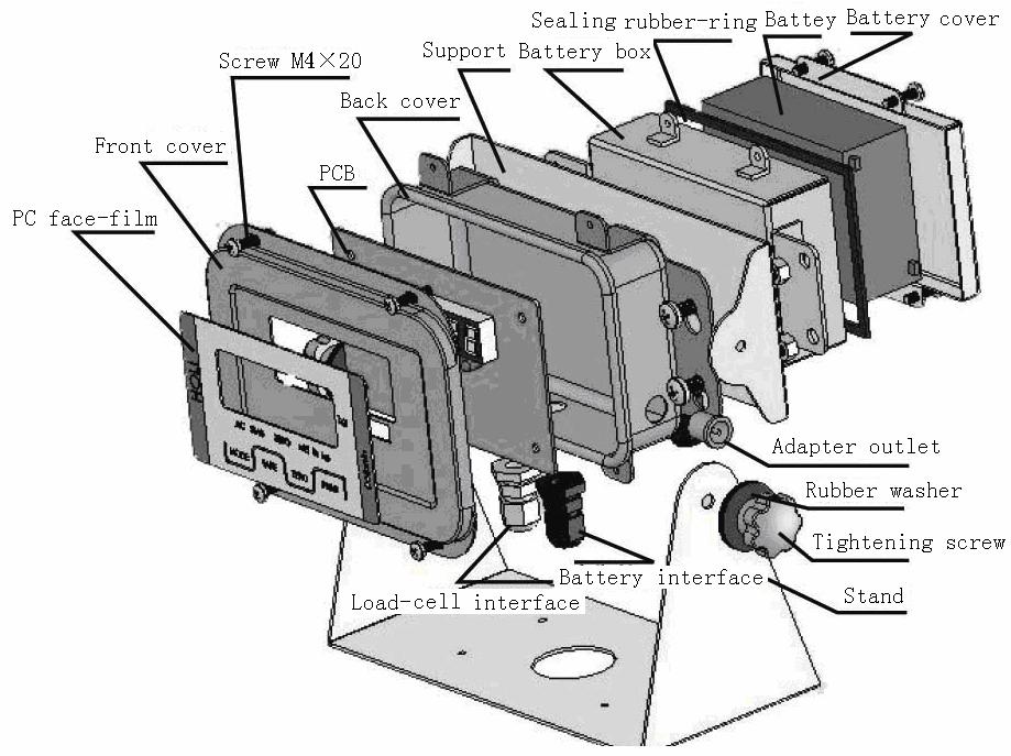
19 Display will not turn on Display turns on But wont weigh Weighing is erratic Under load Weighing is not stable At zero Scale does not Calibrate No sensor output and The display is locked Check power source Not enough current Check sensor hydraulic tee off Check sensor connections Check sensor output counts are moving Check sensor output connections Check fuse Check the Ground cable Check filter setting Check input current Check sensor is counts are positive Check supply current Check all connections including 805 internal power connection Check sensor connections, Check sensor wires are connected to correct wires from the 805 unit. The load may be unstable or bouncing causing a hydraulic spike Lower the weighing cycle height Check the 805 in calibration mode to see the a/d counts of the sensor is ok. Check hydraulic tee off, sensor connections check the test weight value is set correctly Supply current is to low to activate sensor and display The Ws 805 continually monitors the condition of the internal circuits. Any faults or out of tolerance conditions are shown on the display as an error message. In the table below the following terms are used. Error codes Display Description The weighing value is Over Overload alarm under or over the limit Over Over Sensor cable not connected The Ws 805 will show the following messages during the calibration of the unit if a fault is detected. Error shown Display Decryption E32 E32 Not enough Load while trying to calibrate E33 E33 Sensor cables are crossed or not connected Not Enough sensor signal E34 E34 Too much load to while trying to calibrate NO ZERO NO ZERO The scale is not on zero in gross mode while trying to calibrate Ws 805 ENCLOSURE SCHEMATICS
20
WS 10 Weighing indicator USER MANUAL
 WS 10 Weighing indicator USER MANUAL Edition:10052001A Safety Instruction For safety operation follow the safety instructions. WARNING Setting, Calibration Inspection and Maintain of the indicator is prohibited
PK-110. User Manual. American Weigh Scales. PK-110 (0-44lb x 0.05lb / lb x 0.1lb)
") American Weigh Scales PK-110 User Manual PK-110 (0-44lb x 0.05lb / 44-110lb x 0.1lb) Copyright 2012 American Weigh Scales, Inc. All rights reserved. Rev. 1.1 PK-110 Manual Thank you for purchasing the
American Weigh Scales PK-110 User Manual PK-110 (0-44lb x 0.05lb / 44-110lb x 0.1lb) Copyright 2012 American Weigh Scales, Inc. All rights reserved. Rev. 1.1 PK-110 Manual Thank you for purchasing the
Weighloader user manual. Document reference: V2.01
 Weighloader user manual Document reference: 560371-000 V2.01 Note: Prolec Ltd. reserves the right to amend specifications, information and designs without notice. Prolec Ltd. cannot anticipate every possible
DS-520 Digital Indicator Operation Manual 73366
 DS-520 Di gi tal Indi cator Operation Manual 73366 SECTION DS-520 SERIES OPERATING MANUAL INDEX PAGE NUMBER 1.0 GENERAL 2-3 1.1. Features 2 1.2. Keyboard & Display Layout 2 1.3. Key Switch Information
Inscale Measurement Technology Ltd Tel: Fax:
 TCC SERIES Inscale Measurement Technology Ltd 7 Heron Close, St. Leonards-on-Sea. East Sussex TN38 8DX United Kingdom Tel: +44(0)1424 200722 Fax: +44(0)1424 443976 Email: sales@inscale-scales.co.uk Http:www.inscale-scales.co.uk
The Ton-Tel Weighbridge
 The Ton-Tel Weighbridge Plug-and-Weigh Technology Built to last in a tough environment Proven reliability, lower total cost of ownership. Digital Load Cell weight sensors sealed to IP68. Plug-and-Weigh
HYDRAULIC DOCK LEVELER OWNERS MANUAL
 HYDRAULIC DOCK LEVELER OWNERS MANUAL 1 HYDRAULIC DOCK LEVELER OWNERS MANUAL 2 TABLE OF CONTENTS Table Of Contents.. Page 2 Koke Hydraulic Leveler Model Information... Page 3 Hydraulic Dock Leveler Installation
MERIGAUGE MODEL 3900 OPERATING INSTRUCTIONS
 99 Washington Street Melrose, MA 02176 Phone 781-665-1400 Toll Free 1-800-517-8431 Visit us at www.testequipmentdepot.com MERIGAUGE MODEL 3900 OPERATING INSTRUCTIONS Meriam Instrument s MERIGAUGE Model
Adam Equipment LBH SERIES. (P.N , Revision B2, January 2010)
") Adam Equipment LBH SERIES (P.N. 700660113, Revision B2, January 2010) Adam Equipment Company 2010 Easy Reference: Model name of the scale: Serial number of the unit: Software revision number (Displayed
Adam Equipment LBH SERIES (P.N. 700660113, Revision B2, January 2010) Adam Equipment Company 2010 Easy Reference: Model name of the scale: Serial number of the unit: Software revision number (Displayed
WELCOME. Standard Change Makers, Inc. Changer Maintenance Overview General Maintenance Guide for Standard Change-Makers Machines
 WELCOME Standard Change Makers, Inc. Changer Maintenance Overview - - - General Maintenance Guide for Standard Change-Makers Machines Service Maintenance School Reviewing: The SC System Product Line. The
EGT-AF08 USER GUIDE WHEEL WEIGHING SYSTEMS WITH VARIOUS PLATFORMS
 EGT-AF08 USER GUIDE WHEEL WEIGHING SYSTEMS WITH VARIOUS PLATFORMS Revision 1.00 Last update 01/02/2013 Page intentionally left blank. EGT-AF01 USER GUIDE Table of contents 1 INTRODUCTION... 5 2 TECHNICAL
Magner /35-3 Series Currency Counter. Operator's Manual
 Magner 35-2003/35-3 Series Currency Counter Operator's Manual Magner 35-2003 / 35-3 Series Introduction. The MAGNER 35-2003 / 35-3 is the most advanced Currency Counter available today. MAGNER's Design
Operation Manual. Professional Weighing Equipment. MRW SERIES intelligent weighing scale. WASHDOWN WEIGHING SCALE - Dust and Waterproof Scale IP65
 Professional Weighing Equipment MRW SERIES intelligent weighing scale WASHDOWN WEIGHING SCALE - Dust and Waterproof Scale IP65 WITH PIECE COUNTING FUNCTION Operation Manual Section Table of Contents Page
PDM16 & PDM32 User Manual
 MoTeC PDM16 & PDM32 User Manual Contents Introduction... 3 Operation... 4 Configuration...4 PDM Manager Software...4 PC Connection...4 Configuration Concepts...4 Conditions...7 Switch Inputs...7 CAN Inputs...8
Sby SR Instruments, Inc.
 Part No.: MAN947IFS_170629 Page 1 of 12 Sby SR Instruments, Inc. SRV947IFS REMOTE DISPLAY PLATFORM SCALE Operating and Service Manual Part No.: MAN947IFS_170629 Page 2 of 12 TABLE OF CONTENTS TABLE OF
MEDIZINTECHNIK FÜR TIERÄRZTE
 GB Tabel of contents: Operation Instructions Electronic Platfoorm Balances MEDIZINTECHNIK FÜR TIERÄRZTE 1 Technical data 17 2 Fundamental information (general) 18 2.1 Intended use 18 2.2 Inappropriate
Wireless Freezer Manual Installation Guide
 Wireless Freezer Manual Installation Guide Doc # 152-11103-01 Revision DRAFT May 2009 Copyrights Copyright 2008 by. All rights reserved. The information in this document is subject to change without notice.
WP200e Wallbox to CD Changer Adapter
 WP200e Wallbox to CD Changer Adapter Supported Wallbox Models AMI W-40 & W-80 & W-120, 40/80/120 Select AMI WQ-200, 200 Select Rock-Ola 1558 & 500, 160 Select Rock-ola 1555, 200 Select Rowe WRA, WRB &
Instruction number PTI-16-03/09/06/A
 Instruction number PTI-16-03/09/06/A MANUFACTURER OF ELECTRONIC WEIGHING INSTRUMENTS RADWAG 26 600 Radom Bracka 28 Street Phone +48 48 38 48 800, phone/fax. +48 48 385 00 10 Selling department +48 48 366
1600 Currency counting machines
 600 Currency counting machines user guide DE LA RUE CASH SYSTEMS SIZE AUTO CFA 0 8 9 5 6 Walton Rd, Farlington, Portsmouth Hampshire P06 ITJ Tel: + (0) 9 86 Fax: + (0) 9 58 REFERENCE- TML09 600 De La Rue
DIGITAL PORTION SCALE PS-5 OWNER S Manual
 DIGITAL PORTION SCALE PS-5 OWNER S Manual CARDINAL SCALE MFG. CO. 8528-M013-O1 Rev G PO BOX 151 WEBB CITY, MO 64870 Printed in USA 09/00 PH (417) 673-4631 FAX (417) 673-5001 Web Site - http://www.detectoscale.com
Thank you for purchasing the SC-CONVERSION System 500/600 Conversion Kit. This Kit is available in two different versions:
 Rev. 1 (Jun 30, 2016) Thank you for purchasing the SC-CONVERSION System 500/600 Conversion Kit. This Kit is available in two different versions: Part # 4K01328-FI SC-CONVERSION Conversion Kit with MEI
ENGLISH Datasheet JIS Miniature Thermocouple Connector PCB Mounting Socket Types K, J, T, E, R/S & B (JIS Colour Code)
") ENGLISH Datasheet JIS Miniature Thermocouple Connector PCB Mounting Socket Types K, J, T, E, R/S & B (JIS Colour Code) Versatile, high quality, circuit board mounting miniature socket Specially designed
ENGLISH Datasheet JIS Miniature Thermocouple Connector PCB Mounting Socket Types K, J, T, E, R/S & B (JIS Colour Code) Versatile, high quality, circuit board mounting miniature socket Specially designed
BULK BAG FILLING SYSTEMS
 QUICKPAK SERIES 330E BULK BAGGING SYSTEM Unique Pin & Ladder frame adjusts quickly and safely without tools or outside lift device. Pneumatic carriage design can be easily programmed to lift, stretch and
Series. 3 or 12 lb. Capacity. 129 Cramer Road, Jewett, New York USA Fax:
 Installation and Operating Instructions Series 3 or 12 lb. Capacity The Perfect Counting Scale for Any Application Counting Weighing Ink Mixing Inventory Control Batching 129 Cramer Road, Jewett, New York
TF20 Tray Feeder. Instruction Manual. for JEDEC and IEC Standard Trays
 for JEDEC and IEC Standard Trays Instruction Manual 096-0243-003 Data I/O assumes no liability for errors, or for any incidental, consequential, indirect, or special damages, including, without limitation,
ENGLISH Datasheet JIS Miniature Thermocouple Connector In-Line Plugs Types K, J, T, E, R/S & B (JIS Colour Code)
") ENGLISH Datasheet JIS Miniature Thermocouple Connector In-Line Plugs Types K, J, T, E, R/S & B (JIS Colour Code) Range of miniature thermocouple connectors with flat pins to suit thermocouple type Ideal
ENGLISH Datasheet JIS Miniature Thermocouple Connector In-Line Plugs Types K, J, T, E, R/S & B (JIS Colour Code) Range of miniature thermocouple connectors with flat pins to suit thermocouple type Ideal
CONTENTS. 3-1 Unpacking and Checking Installing Components Leveling the Scale... 1
 CONTENTS 1. Introduction... 1 2. Precautions... 1 3. Before Using the Product 3-1 Unpacking and Checking. 1 3-2 Installing Components.... 1 3-3 Leveling the Scale.... 1 4. Product Introduction 4-1 Specifications
64C Amplification Block. Instruction Manual
 64C Amplification Block Instruction Manual Caution: All rights reserved. Quidel Corporation reserves the right to modify this manual at any time without notice. Any part of the manual shall not be duplicated,
Mechatronics Courses by School Period
 Mechatronics Courses by School Period Year One P1 P1 P2 P3 P3 P3 P4 P4 P4 Integrated Systems Industrial Math (Geometry, Trig, Algebra,) Blueprint Reading Machine Tool I (Hand tools-measuring-saws & Drill
dronium TWO AP DRONE with camera
 dronium TWO AP TM DRONE with camera INSTRUCTION MANUAL WWW.PROTOCOLNY.COM THANK YOU. Thank you for your purchase of Protocol s Dronium Two AP With Camera. You are about to experience the best of what remote
GK INDICATOR. (P.N. 9264, Revision K1, July 2011)
") Adam Equipment GK INDICATOR (P.N. 9264, Revision K1, July 2011) V1.17 GK-H scales for Europe V2.25 EC Approved scale V3.32 GK scale for Europe V4.07 GK-H scale for USA V5.32 GK scales for USA Adam Equipment
Adam Equipment GK INDICATOR (P.N. 9264, Revision K1, July 2011) V1.17 GK-H scales for Europe V2.25 EC Approved scale V3.32 GK scale for Europe V4.07 GK-H scale for USA V5.32 GK scales for USA Adam Equipment
OPERATION MANUAL. Electronic Hanging Scale NINGBO AUDDA WEIGHING CO.,LTD
 OCS-A1 Electronic Hanging Scale OPERATION MANUAL NINGBO AUDDA WEIGHING CO.,LTD ADD:no.5, 75th nong, tanshu road (by the west side of electricity station), Ninghai, Ningbo TEL:0574-65231021 (China) 0574-65231022
Daker DK kva. Parallel installation quick start. Part. LE08927AA-09/15-01 GF
 Daker DK 4.5-10 kva Parallel installation quick start Part. LE08927AA-09/15-01 GF Daker DK 4.5-10 kva UK ENGLISH 3 2 Daker DK 4.5-10 kva Index Introduction 2 1 Important Safety Instructions 2 2 Parallel
Product Manual Release 05/17
 Temporary Safety Barrier (TL-2 MASH) Product Manual VHD (v3) www.valmonthighway.com Table of Contents 1.0 ArmorZone Introduction... 3 2.0 Before Installation... 3 3.0 Limitations & Warnings... 3 4.0 System
Precision Automatic Vacuum Control (PAVC+)
") USER GUIDE UGE105-1216 www.conairgroup.com Precision Automatic Vacuum Control (PAVC+) Corporate Office: 724.584.5500 l Instant Access 24/7 (Parts and Service): 800.458.1960 l Parts and Service: 814.437.6861
USER GUIDE UGE105-1216 www.conairgroup.com Precision Automatic Vacuum Control (PAVC+) Corporate Office: 724.584.5500 l Instant Access 24/7 (Parts and Service): 800.458.1960 l Parts and Service: 814.437.6861
This guide can be used to prepare a specification for incorporating free standing jib cranes into a competitively bid construction project.
 GORBEL PRODUCT SPECIFICATIONS 2010 Gorbel, Inc., P.O., Box 593, Fisher, New York 14453-0593 PHONE: 800-821-0086, FAX: 585-924-6273; WEBSITE: www.gorbel.com November SECTION 41 22 31PRIVATE FREE STANDING
This guide can be used to prepare a specification for incorporating free standing jib cranes into a competitively bid construction project.
 SECTION 14651 FREE STANDING JIB CRANE ***** Gorbel, Inc. manufacturers a broad range of material handling cranes including monorail, bridge, gantry, and jib cranes. Numerous work station and industrial
FAST POWER FACTOR REGULATOR. Computer-14df - xx - 144a INSTRUCTION MANUAL ( M / 00A ) (c) CIRCUTOR S.A.
 (c) CIRCUTOR S.A.") FAST POWER FACTOR REGULATOR Computer-14df - xx - 144a INSTRUCTION MANUAL ( M 981 611 / 00A ) (c) CIRCUTOR S.A. -------- POWER FACTOR REGULATOR COMPUTER- 14f --------- Page 2 POWER FACTOR REGULATOR COMPUTER-
FAST POWER FACTOR REGULATOR Computer-14df - xx - 144a INSTRUCTION MANUAL ( M 981 611 / 00A ) (c) CIRCUTOR S.A. -------- POWER FACTOR REGULATOR COMPUTER- 14f --------- Page 2 POWER FACTOR REGULATOR COMPUTER-
Low-profile, 11U high cabinets hold networking equipment, servers, and phone equipment.
 RM140A-R3 RM140A-M-R3 RM145A-R3 RM145A-M-R3 Small Office/Home Office (SOHO) Cabinets Low-profile, 11U high cabinets hold networking equipment, servers, and phone equipment. Fit under most desktops in the
Imperial Series. Model IMP-425/525/625/825/1000AP IMD-425/525/625/825/1000AP IMP-1025/1200/1500/2000AP IMD-1025/1200/1500/2000AP
 Service Manual Imperial Series Model IMP-425/525/625/825/1000AP IMD-425/525/625/825/1000AP IMP-1025/1200/1500/2000AP IMD-1025/1200/1500/2000AP Contents of Service Manual 1. Safety Precautions ------------------------------------------------------------------
Single Pulse Resistance Welder Instruction Pamphlet CD125SP High Accuracy CD Welder
 EN G IN EERI N G Single Pulse Resistance Welder Instruction Pamphlet CD125SP High Accuracy CD Welder Fundamentals of Capacitive Discharge Resistance Welding deliver repeatable welds even during line voltage
Installation Manual. Orion. TL-3 Steel Barrier. VHD (v2)
") Installation Manual Orion TL-3 Steel Barrier VHD (v2) 300914 Table of Contents Orion Introduction.......... 3 Limitations & Warnings. 4 Before Installation..... 3 System Design & Design Considerations
Installation Manual Orion TL-3 Steel Barrier VHD (v2) 300914 Table of Contents Orion Introduction.......... 3 Limitations & Warnings. 4 Before Installation..... 3 System Design & Design Considerations
Shur-Shot X-Proof Hydrogen Fluoride Alarm Operations Manual
 Shur-Shot X-Proof Hydrogen Fluoride Alarm Operations Manual P/N 1000006053 Rev E $7%$QDO\WLFV// //& 733 Dairy Rd. Parkton, Md. 21120 www.atbanalytics.com (410) 733-6365 Table of Contents Chapter 1: Getting
Rexroth - 440RC Solid De-icer Controller Short Form Configuration & Setup Manual
 Electric Drives and Controls Hydraulics Linear Motion and Assembly Technologies Pneumatics Service Rexroth - 440RC Solid De-icer Controller Short Form Configuration & Setup Manual The Drive & Control Company
LED ROTATION BEAM LIGHT
 LED ROTATION BEAM LIGHT MJ-1018(White) INSTRUCTION MANUAL Thank you for choosing our LED rotation beam light. For the sake of your safety, Please read and follow these instructions carefully and keep this
Revision 1 RAM ELEVATORS. Elevator Electrical Planning Guide. RAM Manufacturing Ltd
 RAM ELEVATORS Elevator Electrical Planning Guide This guide is intended for people with an understanding of electricity. If you are not, please consult a licensed electrician as errors in application of
PMA 31-G. English. Printed: Doc-Nr: PUB / / 000 / 00
 PMA 31-G English 1 Information about the documentation 1.1 About this documentation Read this documentation before initial operation or use. This is a prerequisite for safe, trouble-free handling and
MICRO PRODUCTS COMPANY MANUFACTURERS OF PRECISION WELDING MACHINES RW 1,2,3,4 RING/BUTT WELDERS SERVICE MANUAL
 MICRO PRODUCTS COMPANY MANUFACTURERS OF PRECISION WELDING MACHINES RW 1,2,3,4 RING/BUTT WELDERS SERVICE MANUAL 1 TABLE OF CONTENTS 1.0 SPECIFICATIONS 2.0 GENERAL HOOK-UP INSTRUCTIONS 3.0 GENERAL OPERATING
VBC Manual MManualManual. Installation and user manual for the VBC
 VBC400-600 Manual MManualManual Installation and user manual for the VBC400-600 Before You Begin Read these instructions before installing or operating this product. Note: This installation should be made
Trouble-Shooting Asphalt Content Problems
 Trouble-Shooting Asphalt Content Problems Page 1 of 6 Trouble-Shooting Asphalt Content Problems Asphalt content is controlled differently in a drum-mix type plant and a batch type plant. Therefore, trouble-shooting
X30 System Components
 X30 System Components X30 Monitor - Monitor is 12.1 inches - LINUX operating system not windows - Can-based communication. No serial ports - New part number 3132-10 LED Light Bar Battery Status LED Light
Technical System Catalogue Modular PDU (PSM)
") Technical System Catalogue Modular PDU (PSM) Benefits of PSM busbars at a glance Modular configuration, flexibly extendible Redundant designs in busbars are supported Vertical mounting in the rack without
Technical System Catalogue Modular PDU (PSM) Benefits of PSM busbars at a glance Modular configuration, flexibly extendible Redundant designs in busbars are supported Vertical mounting in the rack without
AHP WELDS USER MANUAL
 AHP WELDS USER MANUAL Alpha-TIG200X (version III) Contents 1. Safety... 2 2. About your AlphaTig 200X... 3 3. Parameters... 4 4. Panel Index... 5 5. Setup Instructions... 6 6. Operating Instructions...
Model 5511 & 6611 Scale Controller User s Manual Version 2.66 January Thompson Scale Company WEIGHING SYSTEMS & PACKAGING MACHINERY CONTROLS
 Model 5511 & 6611 Scale Controller User s Manual Version 2.66 January 2016 Thompson Scale Company WEIGHING SYSTEMS & PACKAGING MACHINERY CONTROLS MODEL 5511 SCALE CONTROLLER VERSION 2.66 TOOLS CALIBRATE
MOBILE COLUMN LIFT ST ST Superior flexible solutions with an 8.5 ton or 10.0 ton lifting capacity STERTIL SUPERIOR SOLUTIONS
 MOBILE COLUMN LIFT ST 1085 - ST 1100 Superior flexible solutions with an 8.5 ton or 10.0 ton lifting capacity STERTIL SUPERIOR SOLUTIONS Superior Solutions The Stertil Group provides customised and technically
Océ DFS10. Operator Manual
 Océ DFS10 Operator Manual Océ-Technologies B.V. All rights reserved Id: 7241873 Approvals and certifications Safety Europe Approved by Underwriters Laboratories Inc. North America This equipment is listed
Adam Equipment ADK SERIES
 Adam Equipment ADK SERIES (P.N. 2693, Revision F7, January 2006) @Adam Equipment Company 2006 1 CONTENTS 1.0 INTRODUCTION... 2 2.0 SPECIFICATIONS... 2 3.0 INSTALLATION... 3 3.1 UNPACKING YOUR BALANCE...
PalletPal Pallet Inverter / Rotator
 PalletPal Pallet Inverter / Rotator Owner s Manual SOUTHWORTH PRODUCTS CORP PO Box 1380, Portland, ME 04104-1380 Telephone: 1-800-743-1000 or 207-878-0700 Fax: 207-797-4734 www.southworthproducts.com service@southworthproducts.com
Sensor unit MC2 for toxic gases and oxygen with analog output
 Page 1 July 2016-2 Exchangeable sensor unit including digital value processing, temperature compensation and self control for the continuous monitoring of the ambient air. The sensor unit MC2 houses a
PTSV403. Camera Parking Assist System. Camera PTSV
 PTSV403 Camera Parking Assist System PTSV403 75545485 Camera Sensor Contents Reasons to choose Steelmate User's Manual Reasons to choose Steelmate -------------------- Disclaimer --------------------------------------------
Are you looking for a real boost in your forklift productivity?
 Are you looking for a real boost in your forklift productivity? We offer reach trucks that can increase operating time by up to 30%: ETV 110 / 112 ETV / ETM 214 / 216 ETV / ETM 318 / 320 / 325 1 You can
Pallet Safe: Installation Supplement Rev
 Pallet Safe: Installation Supplement Rev. 4-1-13 Smartscan Incorporated, 33083 Eight Mile Road, Livonia MI 48152 Tel: (248)477-2900 Fax: (248) 477-7453 Web: www.smartscaninc.com SMARTSCAN INCORPORATED
Model: LI55 DataView Level Controller Instruction Manual
 Model: LI55 DataView Level Controller www.flowline.com 10500 Humbolt St. Los Alamitos CA 90720 USA Tel (562) 598-3015 Fax (562) 431-8507 Disclaimer The information contained in this document is subject
User s Manual. Chart Projector GCP-7000
 User s Manual Chart Projector GCP-7000 ------------------------------------------------------------------------ Chart Projector GCP-7000 1 IMPORTANT NOTICE This product may malfunction due to electromagnetic
Installation, Inspection and Maintenance of Dry Type Transformers
 Dry Type TX 1 of 8 Installation, Inspection and Maintenance of Dry Type Page 1 of 8 Dry Type TX 2 of 8 Table Of Contents Page Number 1. General... 3 2. Installation... 3 3. Safety Inspections... 4 4. Safety
Kelley HULK Dock Lifts and Ergonomic Lift Tables
 Kelley HULK Dock Lifts and Ergonomic Lift Tables Kelley HULK Lift Products help increase productivity and employee safety with innovative, cost effective solutions to the unique challenges associated with
SIWAREX FTC-B Weighing Module for Belt Scales Set-up of SIWAREX FTC with SIWATOOL FTC_B
 SIWAREX FTC-B Weighing Module for Belt Scales Set-up of SIWAREX FTC with SIWATOOL FTC_B Quick Guide For modules with order number 7MH4900-3AA01 1 Hardware Requirements... 3 2 Connections... 5 3 SIWATOOL
Barkeep Instructions for the Escali SmartConnect Scale
 Barkeep Instructions for the Escali SmartConnect Scale These instructions are for users of the Escali SmartConnect Kitchen Scale purchased from barkeepapp.com. Users of any other digital scales and/or
FORM HEADWALL. FORM HEADWALL (floating) (floating) Installation Manual
 (floating) Installation Manual") FORM HEADWALL (floating) Installation Manual FORM HEADWALL (floating) OVERVIEW The Form is a UL-listed configurable headwall system. This system includes multiple horizontal equipment channels integrated
FORM HEADWALL (floating) Installation Manual FORM HEADWALL (floating) OVERVIEW The Form is a UL-listed configurable headwall system. This system includes multiple horizontal equipment channels integrated
Calibration-approved belt scales according to MID
 Matt Morrissey, Product Manager, Weighing Technology Calibration-approved belt scales according to MID Industries around the world use belt scales every day to weigh solid materials on conveyors gravel
Field Inspection Manual Part: 2-ASTP Section: 3 - DTWS Page: 1 of 18. Automatic Weighing Devices Issued: Revision Number: Original
 Field Inspection Manual Part: 2-ASTP Section: 3 - DTWS Page: 1 of 18 REFERENCE Weights and Mesures Regulations, NAWDS & the National Technical Training Bulk Weigher Training Module. PURPOSE The following
HCP-7000 Opreator s Manual 1. Operator s Manual.
 -------------------------------------------------------------------- HCP-7000 Opreator s Manual 1 Operator s Manual Chart Projector 2 HCP-7000 Operator s Manual -----------------------------------------------------------------------
1. Vertical reciprocating conveyor, Hydraulic straddle VRC.
 PART 1: GENERAL 1.01 Section Includes: 1. Vertical reciprocating conveyor, Hydraulic straddle VRC. a. Machine, controller, platform, structural steel hoist frame. b. Wire mesh enclosure and gates. Related
Pre-installation Manual CONCEPT 301 D/401 D/501 D
 Pre-installation Manual CONCEPT 301 D/401 D/501 D Pre-installation Manual CONCEPT 301 D/401 D/501 D Concept 301 D T11416 Edition BA, January 2015 This book has part No 10077155 0-2 This manual is published
Operational Manual. Spectrophotometer Model: SP-830 PLUS. Metertech Inc. Version 1.07
 Operational Manual Spectrophotometer Model: SP-830 PLUS Metertech Inc. Version 1.07 Metertech Inc. provides this publication as is without warranty of any kind, either express or implied, including, but
ArmorZone TL-2 Barrier and End Treatment
 ArmorZone TL-2 Barrier and End Treatment Product and Installation Manual ANOTHER AMORFLEX DEVELOPMENT Table of contents Introduction 3 System Overview 3 Before Installation 3 Limitations and Warnings 4
Global Water Instrumentation, Inc.
 Global Water Instrumentation, Inc. 151 Graham Road P. O. Box 9010 College Station, TX 77842-9010 T: 800-876-1172 Int l: (979) 690-5560, F: (979) 690-0440 E-mail : globalw@globalw.com WS750 Sampler 01-457
Global Water globalw.com
 Global Water Instrumentation, Inc. 151 Graham Road P.O. Box 9010 College Station, TX 77842-9010 Telephone : 800-876-1172 International : (979) 690-5560, Fax : (979) 690-0440 e-mail : globalw@globalw.com
Please read these instructions before use and retain for future reference
 User Manual DPF-830 Please read these instructions before use and retain for future reference 1 CONTENTS 1. Safety Precautions ------------------------------------------------------------------------------3
Offi ceright Folding Machine DF800/DF900
 Offi ceright Folding Machine DF800/DF900 Operator Guide English Version Table of Contents Chapter 1 Chapter 2 Chapter 3 Introduction Safety...1-1 To The Operator...1-3 About your System...1-3 Machine
CW Series FLOORSCALES. ISO 9001:2000 Registered
 CW Series FLOORSCALES ISO 9001:2000 Registered Intercomp, the world leader in portable scales for the transportation and material handling industry, provides the most comprehensive line of bench, floor,
AXIS II RC DRONE WITH CAMERA
 AXIS II RC DRONE WITH CAMERA THANK YOU. Thank you for your purchase of Protocol s Axis II RC Drone With Camera. You are about to experience the best of what remote control flight has to offer. We strongly
INDEX. 1 Introduction. 2 Software installation. 3 Open the program. 4 General parameters. 5 Tuning
 SET UP MANUAL INDEX 1 Introduction 2 Software installation 3 Open the program 4 General parameters 5 Tuning 2 1 Introduction Here below the instruction to use the FLYJET software. 1.1 Software features
Best Selection for Your Business. Electronic Pricing Scale. User s Manual. (Model: TP-31)
") Best Selection for Your Business Electronic Pricing Scale User s Manual (Model: TP-31) CATALOG 1. Foreword... 2 1.1. Introductions... 2 1.2. Main functions and features... 2 1.3. Specification... 2 1.4.
Best Selection for Your Business Electronic Pricing Scale User s Manual (Model: TP-31) CATALOG 1. Foreword... 2 1.1. Introductions... 2 1.2. Main functions and features... 2 1.3. Specification... 2 1.4.
AP5K-C Precision AC Double-Pulse Spot Welding Machine User s Manual Shenzhen Will-Best Electronics Co., Ltd
 AP5K-C Precision AC Double-Pulse Spot Welding Machine User s Manual Shenzhen Will-Best Electronics Co., Ltd 1 Content 1. Introduction...3 1.1 Functions...3 1.2 Units of AP5K-C...4 2. The Initial Installation
VENTO WIFI DRONE WITH LIVE STREAMING CAMERA
 VENTO WIFI DRONE WITH LIVE STREAMING CAMERA INSTRUCTION MANUAL THANK YOU. Thank you for your purchase of Protocol s Vento Wifi Drone with Live Streaming Camera. You are about to experience the best of
Good Husband Brand Remote Lighting Lifter
 Good Husband Brand Remote Lighting Lifter National Patent Number:200520069085.5 200520075680.X 200520075677.8 200520075679.7 International Patent Number: PCT/CN2006/000409 Product Standard: Q/QABC002-2009
July P Wide Format Stacker User Guide
 July 2009 701P49768 Wide Format Stacker User Guide 2009 Xerox Corporation. All rights reserved. Xerox and the sphere of connectivity design are trademarks of Xerox Corporation in the United States and/or
Instruction Manual HT 24 BM-D2400 Homogenizer
 Instruction Manual HT 24 BM-D2400 Homogenizer Foreword Thank you for purchasing a HT 24 Homogenizer. This manual contains instructions for the proper operation and care of this instrument. Please read
Unit Substation Transformer Construction Checklist (under 500 kva)
") Unit Substation Transformer Checklist (under 500 kva) Building: Location: Submittal / Approvals Submittal. The above equipment and systems integral to them are complete and ready for functional testing.
Unit Substation Transformer Checklist (under 500 kva) Building: Location: Submittal / Approvals Submittal. The above equipment and systems integral to them are complete and ready for functional testing.
Isco EZ TOC. TOC and TC Analysis Made Easy. Continuous on-line TOC/TC measurement using low-temperature oxidation
 Isco EZ TOC Continuous on-line TOC/TC measurement using low-temperature oxidation Easy Programming High Efficiency UV Reactor Enhanced NDIR Detector Flexible Four-Motor Pump System Advanced Dual Calibration
GIGA Commercial Drone. Owner s Manual. For Owner s Manual updates, warranty information, and support, visit:
 GIGA -6000 Commercial Drone Owner s Manual For Owner s Manual updates, warranty information, and support, visit: www.mota.com/giga-6000 Please read the Owner s Manual before your first flight. It has information
 763.389.9475 www.erdmanautomation.com The Erdman 3M VHB Structural Glazing Tape Applicator, Frame Assembly & Glass Lay-in System Erdman 3M VHB Structural Glazing Tape Applicator, Frame Assembly and Glass
Gerber M Series Site Requirements
 Gerber M Series Site Requirements Preparing for the arrival of your new machine. P rior to the arrival of your Gerber M Series Cutting System there are certain things you can prepare to facilitate a quick
Xerox Nuvera Xerox Production Stacker Operator Manual
 Software Version 11.6 October 2012 702P00782 Xerox Nuvera Xerox Production Stacker Xerox Nuvera 100/120/144/157 EA Production System Xerox Nuvera 100/120/144 MX Production System Xerox Nuvera 200/288/314
Tank Scale Service Checklist
 Tank Scale Service Checklist Specifying Service for Optimized Weighing Processes Selecting the right weighing equipment is an important first step to ensuring that your weighing processes are able to meet
SST-II HYDRAULIC BI-FOLD SPECIFICATIONS
 PART 1 GENERAL 1.01 DESCRIPTION A. General 1. Furnish SST-II Hydraulic Bi-Fold System complete from one manufacturer. Provide all labor, materials, tools and equipment to furnish the SST-II Bi-Fold System
Maintenance Bypass Breaker Cabinet Series Configuration 5. Installation and Operation Manual
 Maintenance Bypass Breaker Cabinet 90881 Series Configuration 5 Installation and Operation Manual 03/13/2012 2 755-00084-C5 R03 Copyright 2012 C&C Power, Inc. All rights reserved. C&C Power, Inc. 395 Mission
Storm Drone 6 GPS DEVO 7 Setup for NAZA-M Lite
 DEVO 7 Setup for NAZA-M Lite Step 1 - Set Fixed ID on the transmitter! Skip this part if you have a brand new Storm Drone 6 GPS, we have already done before we ship. 1. 2. 3. 4. 5. 6. 7. 8. 9. Turn on