N ORTH A MERICAN ELECTRIC RELIABILITY COUNCIL
|
|
|
- Janis Blankenship
- 6 years ago
- Views:
Transcription
1 N ORTH A MERICAN ELECTRIC RELIABILITY COUNCIL Princeton Forrestal Village, Village Boulevard, Princeton, New Jersey ATCT Drafting Team Wednesday, November 16, :00 a.m. 1:00 p.m. Eastern Time (U.S. & Canada). Phone number 1(732) Conference code is Conference Call Agenda 1. Attendance and Introductions L. Middleton 2. NERC Antitrust Compliance Guidelines B. Lohrman 3. Work Plan L. Middleton a. ATC/TTC Complete Reviews 4. Review Regional ATC/TTC/CMB/TRM documents a. WECC b. Entergy c. FRCC d. SPP 5. Review Standards MOD-001 to MOD-009 in preparation for revisions a. Analysis b. ftp:// c. ftp:// 6. Reference Documents a. Comments on NERC SARs: ftp:// mments.pdf b. Comments to FERC NOI on ATC: Revision-RF.html A New Jersey Nonprofit Corporation Phone Fax URL
2 Item 2 N ORTH AMERICAN ELECTRIC RELIABILITY COUNCIL Princeton Forrestal Village, Village Boulevard, Princeton, New Jersey I. GENERAL NERC ANTITRUST COMPLIANCE GUIDELINES It is NERC s policy and practice to obey the antitrust laws and to avoid all conduct that unreasonably restrains competition. This policy requires the avoidance of any conduct that violates, or that might appear to violate, the antitrust laws. Among other things, the antitrust laws forbid any agreement between or among competitors regarding prices, availability of service, product design, terms of sale, division of markets, allocation of customers or any other activity that unreasonably restrains competition. It is the responsibility of every NERC participant and employee who may in any way affect NERC s compliance with the antitrust laws to carry out this commitment. Antitrust laws are complex and subject to court interpretation that can vary over time and from one court to another. The purpose of these guidelines is to alert NERC participants and employees to potential antitrust problems and to set forth policies to be followed with respect to activities that may involve antitrust considerations. In some instances, the NERC policy contained in these guidelines is stricter than the applicable antitrust laws. Any NERC participant or employee who is uncertain about the legal ramifications of a particular course of conduct or who has doubts or concerns about whether NERC s antitrust compliance policy is implicated in any situation should consult NERC s General Counsel immediately. II. PROHIBITED ACTIVITIES Participants in NERC activities (including those of its committees and subgroups) should refrain from the following when acting in their capacity as participants in NERC activities (e.g., at NERC meetings, conference calls and in informal discussions): Discussions involving pricing information, especially margin (profit) and internal cost information and participants expectations as to their future prices or internal costs. Discussions of a participant s marketing strategies. Discussions regarding how customers and geographical areas are to be divided among competitors. Discussions concerning the exclusion of competitors from markets. Discussions concerning boycotting or group refusals to deal with competitors, vendors or suppliers. Approved by NERC Board of Trustees, June 14, 2002 Technical revisions, May 13, 2005 A New Jersey Nonprofit Corporation Phone Fax URL
3 III. ACTIVITIES THAT ARE PERMITTED From time to time decisions or actions of NERC (including those of its committees and subgroups) may have a negative impact on particular entities and thus in that sense adversely impact competition. Decisions and actions by NERC (including its committees and subgroups) should only be undertaken for the purpose of promoting and maintaining the reliability and adequacy of the bulk power system. If you do not have a legitimate purpose consistent with this objective for discussing a matter, please refrain from discussing the matter during NERC meetings and in other NERC-related communications. You should also ensure that NERC procedures, including those set forth in NERC s Certificate of Incorporation and Bylaws are followed in conducting NERC business. Other NERC procedures that may be applicable to a particular NERC activity include the following: Reliability Standards Process Manual Organization and Procedures Manual for the NERC Standing Committees System Operator Certification Program In addition, all discussions in NERC meetings and other NERC-related communications should be within the scope of the mandate for or assignment to the particular NERC committee or subgroup, as well as within the scope of the published agenda for the meeting. No decisions should be made nor any actions taken in NERC activities for the purpose of giving an industry participant or group of participants a competitive advantage over other participants. In particular, decisions with respect to setting, revising, or assessing compliance with NERC reliability standards should not be influenced by anti-competitive motivations. Subject to the foregoing restrictions, participants in NERC activities may discuss: Reliability matters relating to the bulk power system, including operation and planning matters such as establishing or revising reliability standards, special operating procedures, operating transfer capabilities, and plans for new facilities. Matters relating to the impact of reliability standards for the bulk power system on electricity markets, and the impact of electricity market operations on the reliability of the bulk power system. Proposed filings or other communications with state or federal regulatory authorities or other governmental entities. Matters relating to the internal governance, management and operation of NERC, such as nominations for vacant committee positions, budgeting and assessments, and employment matters; and procedural matters such as planning and scheduling meetings. Any other matters that do not clearly fall within these guidelines should be reviewed with NERC s General Counsel before being discussed. Approved by NERC Board of Trustees, June 14, 2002 Technical revisions, May 13,
4 Summary of ATC/TRM Industry SAR Comments Draft Item 3a Summary for Question # 1: Is there a reliability need for the proposed standard? In general, most people felt that there is a reliability need for the proposed standard. Most of the parties that responded had no comments, however two that did comment felt that TTC and TRM were reliability quantities and that ATC and AFC were market quantities. Nearly all commented that yes there is a reliability need Of the 14 that responded only four commented with any level of negative response, but just for ATC. These four stressed TTC is a reliability quantity and should be addressed. ATCT DT yes, ATCT DT ATCT DT believes that TTC/ATC are not reliability indicators, but are derived from reliability-based values, assumptions and criteria. However, there is a need to acknowledge the relationship between TTC and ATC values. The drafting team believes that both these quantities should be addressed by this reliability standard. Commenter #1 Commenter #2 FRCC EXELON There is a reliability need for this standard especially as it pertains to TTC and TRM. Two parties believe that ATC and AFC are market quantities but there is no feed back from the other commenters one way or the other on this position. Recommended analysis / reply of drafting team Summary of submitted comment Recommended analysis / reply of drafting team ATCT DT agrees n/a NERC SAR Drafting Team October 28, 2005 Page 1
5 Summary of ATC/TRM Industry SAR Comments Draft HYDRO QUEBEC TRANS ENERGIE ONTARIO ISO ISO NE RTO/ISO Standards Review Committee MRO North Carolina Municipal Power Agenct Number 1 ATC Task Force of NERC Planning Committee Northeast Power Coordinating Council NYISO ATCT DT believes that TTC/ATC are not reliability indicators, but are derived from reliability-based values, assumptions and criteria. However, there is a need to acknowledge the relationship between TTC and ATC values. The drafting team believes that both these quantities should be addressed by this reliability standard. The transparency of how ATC/AFC is derived is a market issue. na na Na na ATCT DT agrees with the comment ATCT DT believes that TTC/ATC are not reliability indicators, but are derived from reliability-based values, assumptions and criteria. However, there is a need to acknowledge the relationship between TTC and ATC values. The drafting team believes that both these quantities should be addressed by this reliability standard. The transparency of how ATC/AFC is derived is a market issue. NERC SAR Drafting Team October 28, 2005 Page 2
6 Summary of ATC/TRM Industry SAR Comments Draft Southern Company Generation Southern Company Transmission WPS Resources NERC SAR Drafting Team October 28, 2005 Page 3
7 Summary for Question # 02: Summary of ATC/TRM Industry SAR Comments Draft Is the proposed scope of the standard sufficient to address reliability concerns; i.e. should the proposed standard include standardizing methods for the calculation of ATC, AFC, and TTC? Of 14 responses, 6 were yes, 6 were no, and 2 were yes and no. The majority of comments are in agreement, however. In general, most people disagree with the idea of a standard methodology for ATC/TTC/AFC calculation. NCMPA1 is the only exception. Nearly all commented about the need for increased data exchange, coordination, and documentation to promote transparency. ATCT DT yes, the drafting team believes that a single methodology should be developed within each RRO. The development of the methodology should be transparent and clearly documented. If options are provided in the regional methodology for a TSP crossing regional boundaries, the TSP must clearly document which option is being used. FRCC EXELON HYDRO QUEBEC TRANS ENERGIE No to one methodology, Yes to RRO (including RTOs/ISOs) standard methodology. Standard should require RROs (including RTOs/ISOs) to develop regional methodolgy No to one methodology. Certain aspects of the calculation must be required in the method, but one method should not be made standard. Standard must state that aspects of the calculation critical to the reliability be required, i.e. exchange and use of data, monitoring all critical flowgates. What method the ATC calculator uses to incorporate these critical aspects is up to them. Proposed scope is already too detailed/prescriptive. NERC SAR Drafting Team October 28, 2005 Page 4
8 Summary of ATC/TRM Industry SAR Comments Draft ONTARIO ISO ISO NE RTO/ISO Standards Review Committee MRO North Carolina Municipal Power Agenct Number 1 ATC Task Force of NERC Planning Committee Northeast Power Coordinating Council NYISO Southern Company Generation No to one methodology. Differences in methodologies may exist, but the processes must be coordinated and work together. No to one methodology. Differences in methodologies may exist, but the processes must be coordinated and work together. Yes to one methodology Further standardization of certain key elements is necessary Standard must define certain key elements. NERC ATC and TTC methodology must be expanded to include and describe these key elements. Relationship of AFC to ATC and TTC, and how they are used and coordinated must be clearly defined. No to one methodology Standardization must recognize inherent differences between markets. Coordination and documentation of calculation method would improve transparency. No to one methodology Standard should focus on increasing the transparency of study assumptions and methods. Standard should increase communication and coordination of transfer capability calculations. NERC SAR Drafting Team October 28, 2005 Page 5
9 Summary of ATC/TRM Industry SAR Comments Draft Southern Company Transmission WPS Resources No to one methodology Standard should focus on increasing the transparency of study assumptions and methods. No reliability need to mandate a prescribed detailed procedure for calculating TTC/ATC/AFC. Discussion: When a commenter refers to standard methodology, it is unclear if they are referring to a standard method for only Total Transfer Capability (TTC), Available Transfer Capability (ATC), or Available Flowgate Capability (AFC) or for all three. Further, If they are referring to TTC it is unclear if they mean: o How a specific parameter or set of parameters are used or derived (example A below) o the ruleset for applying a study method (example B below) o a set of guiding principles such as used in the SERC supplement IE1,IE2 (i.e.: TSP must include the following parameters in the calculation). If they are referring to ATC or AFC, for most ATC is defined in pro-forma tariff, something example C below, and it is unclear if the reference is to a component of the equation or the equation itself. Example A: The assumptions and parametersand used to create a study case or set of study cases, i.e.: o Study period o Dispatch method o Load forecast o Generation and Transmission outages o Ambient rating corrections o Partial path transactions o Loop flows o CBM, TRM implicit / explicit Example B: The ruleset for executing a transfer capability study: NERC SAR Drafting Team October 28, 2005 Page 6
10 Summary of ATC/TRM Industry SAR Comments Draft o Type of transfer (simultaneous, non-simultaneous) o Cutoff o Simultaneous transfer weighting o Transfer test level o Transfer type (gen-gen, gen-load, load-gen, load-load) for imports, exports, internal Example C: CBM) ATC = TTC TRM existing transmission commitments (including AFC = Flowgate rating Baseflow NERC SAR Drafting Team October 28, 2005 Page 7
11 Summary for Question # 3: Summary of ATC/TRM Industry SAR Comments Draft Do you agree with the scope of the proposed standard? referring to MOD Documentation of TTC and ATC Calculation Methodologies. In general, most people felt that the scope of the proposed standard was appropriate. A simple tally of the 14 Yes or No responses comes to 9 Yes, 4 No with one Yes and No. This question (#3) is related to the responses to question #2, and several responders to question #3 simply referred to comments in their response to #2. Most felt that standardization of the particular method of ATC/TTC calculation (i.e. a prescriptive requirement) was not necessary, although several felt that further standardization of certain coordination elements would improve and strengthen the ATC/TTC calculation process (from responses to question #2). Nearly all commented that (For question #3, few respondents had substantive comments.) And some asked for clarification on the applicability of any portion of a standard to either short-term or long-term (service as defined in FERC Order 888,889,638, etc.) TTC/ATC study methods. Commenter #1 Excelon Commenter #2 FRCC Agreed with scope, no additional comment. Recommended analysis / reply of drafting team: None required. Agreed with scope, no additional comment. Recommended analysis / reply of drafting team: None required. NERC SAR Drafting Team October 28, 2005 Page 8
12 Summary of ATC/TRM Industry SAR Comments Draft Commenter #3 Hydro Quebec Commenter #4 Ontario ISO Commenter #5 ISO NE Commenter #6 RTO/ISO SRC Commenter #7 MRO Responded Yes and No, Commented that the standard should be limited to TTC/TFC for reliability purposes and ATC/AFC should be addressed by NAESB. Recommended analysis / reply of drafting team: The responder apparently feels that only TTC and TFC are quantities that have reliability significance, while ATCs and AFCs are manipulated by differing market rules (from response to #1). The responder fails to recognize the relationship between the quantities. The calculation of TTC/TFC and ATC/AFC (because ATC/AFC are not independent of TTC/TFC, rather they are a subset of TTC/TFC) requires adherence to reliability standards (the purpose of this team), sound engineering principles and good utility practices which are not market rules that could be delegated to NAESB. Agreed with scope, no additional comment. Recommended analysis / reply of drafting team: None required.. Agreed with scope, no additional comment. Recommended analysis / reply of drafting team: None required.. Recommended analysis / reply of drafting team Agreed with scope, no additional comment. Recommended analysis / reply of drafting team: None required. NERC SAR Drafting Team October 28, 2005 Page 9
13 Summary of ATC/TRM Industry SAR Comments Draft Commenter #8 N. Carolina MPA#1 Commenter #9 ATC TF/NERC Commenter #10 NPCC Commenter #11 NYISO Commenter #12 SOCO Gen Responded No. Commented that the scope should include standardized ATC/TTC/AFC calculations and required coordination between regions. Recommended analysis / reply of drafting team: More standardization and greater coordination between regions is a global theme of the LTATF report and their recommendations and the primary goal of the drafting team. The LTATF also recognized, however that a prescriptive methodology would not be appropriate because regional and market model differences must be accommodated for a standard that will apply to all calculators. Rigid standardization of the process might have the undesirable effect of reducing currently available ATC/AFC by placing too much emphasis on the method, and too little on the many variables that can and should be considered, that are not the same everywhere. (Environmental considerations, for example.). Recommended analysis / reply of drafting team Agreed with scope, no additional comment. Recommended analysis / reply of drafting team: None required.. Recommended analysis / reply of drafting team. Recommended analysis / reply of drafting team NERC SAR Drafting Team October 28, 2005 Page 10
14 Summary of ATC/TRM Industry SAR Comments Draft Commenter #13 SOCO Transm. Commenter #14 WPS Resources. Recommended analysis / reply of drafting team Agreed with scope, no additional comment. Recommended analysis / reply of drafting team: None required. NERC SAR Drafting Team October 28, 2005 Page 11
15 Summary for Question # 4: Summary of ATC/TRM Industry SAR Comments Draft Are there aspects of the proposed standard you believe should be developed as a business practice through NAESB? Note: NAESB has a proposal for companion business practice - R05004) Of 14 responses, 4 were yes, 10 were no. The common thread was that some aspects of the calculation should be developed as business practices by NAESB. There was one comment focused on the separation between business practices and reliability issues. A couple of entities indicated the need for CBM to be included in this standard and not in a business practice standard EXELON FRCC HYDRO QUEBEC TRANS ENERGIE ONTARIO ISO ISO NE No No, but where necessary, business practices should be developed. However, such business practices should not address reliability issue Certain aspects of every transfer capability calculation deal with market needs and may be better addressed via a business practice standard. The DT agrees that such efforts should not address reliability issues. Yes. ATC/AFC values are quantities required by the market and therefore should be defined by NAESB To the extent the issues are related to market needs and do not impact reliability, it would be appropriate for NAESB to define appropriate standards. No No NERC SAR Drafting Team October 28, 2005 Page 12
16 Summary of ATC/TRM Industry SAR Comments Draft RTO/ISO Standards Review Committee MRO North Carolina Municipal Power Agenct Number 1 ATC Task Force of NERC Planning Committee Northeast Power Coordinating Council NYISO No No. There may be certain practices that should addressed by NAESB, but compliance with resulting standards must be voluntary. To the extent the issues are related to market needs and do not impact reliability, it would be appropriate for NAESB to define appropriate standards. If a standard is defined, it must be adhered to; voluntary compliance is not an effective way of achieving industry-wide standardization. No Yes. Certain aspects of the AFC/ATC process need to be addressed by NAESB. Standards must focus on process, not the tools. Reliability issues must be handled by NERC. To the extent the issues are related to market needs and do not impact reliability, it would be appropriate for NAESB to define appropriate standards. It is prudent to have standards define the process, not the implementation details. Yes. Market specific quantities should be addressed by NAESB. To the extent the items are related to market needs and do not impact reliability, it would be appropriate for NAESB to define appropriate standards. No NERC SAR Drafting Team October 28, 2005 Page 13
17 Summary of ATC/TRM Industry SAR Comments Draft Southern Company Generation Southern Company Transmission WPS Resources No. Would like to see CBM remain in this standard as it is an important component of grid reliability. CBM should not become a business practice standard. CBM is addressed in a companion SAR on CBM/TRM. No. Would like to see CBM remain in this standard as it is an important component of grid reliability. CBM should not become a business practice standard. CBM is addressed in a companion SAR on CBM/TRM. Yes NERC SAR Drafting Team October 28, 2005 Page 14
18 Summary for Question # 5: Summary of ATC/TRM Industry SAR Comments Draft Do you agree with the list of entities to which the standard would apply? In general, most people felt that MOD should apply to one or more additional entities. Most felt that standardization was N/A Nearly all commented that the standard should apply to the Transmission Planner, Planning Authority, and Regional Reliability Organization. And some that asked for the standard to apply to the Transmission Owner and Reliability Coordinator. Ron Falsetti Ontario Independent Electricity System Operator Kathleen M. Goodman ISO New England No. Aspects of this standard would also apply to Transmission Planner, Transmission Owner, Planning Authority, RC and Regional Reliability Organization. Recommended analysis / reply of drafting team: RROs should be required to document their assumptions and methodologies. Drafting Team should discuss whether the standard applies to Transmission Planner, Transmission Owner, Planning Authority, Reliability Coordinator, Load Serving Entity, Purchase Selling Entity, or Market Operator. No. Aspects of this standard will also apply to Transmission Planner and Regional Reliability Organization. Recommended analysis / reply of drafting team: RROs should be required to document their assumptions and methodologies. Drafting Team should discuss whether the standard applies to Transmission Planner, Transmission Owner, Planning Authority, Reliability Coordinator, Load Serving Entity, Purchase Selling Entity, or Market Operator. NERC SAR Drafting Team October 28, 2005 Page 15
19 Summary of ATC/TRM Industry SAR Comments Draft Karl Tammar RTO/ISO Standards Review Committee Ken Goldsmith Midwest Reliability Organization Matt Schull North Carolina Municipal Power Agency Number 1 No. Aspects of this standard would also apply to Transmission Planner, Transmission Owner, Planning Authority, RC and Regional Reliability Organization. Recommended analysis / reply of drafting team: RROs should be required to document their assumptions and methodologies. Drafting Team should discuss whether the standard applies to Transmission Planner, Transmission Owner, Planning Authority, Reliability Coordinator, Load Serving Entity, Purchase Selling Entity, or Market Operator. No. Aspects of this standard should also apply to Transmission Planner, Transmission Owner and Regional Reliability Organization. Recommended analysis / reply of drafting team: RROs should be required to document their assumptions and methodologies. Drafting Team should discuss whether the standard applies to Transmission Planner, Transmission Owner, Planning Authority, Reliability Coordinator, Load Serving Entity, Purchase Selling Entity, or Market Operator. Yes. Recommended analysis / reply of drafting team: None. NERC SAR Drafting Team October 28, 2005 Page 16
20 Summary of ATC/TRM Industry SAR Comments Draft Paul B. Johnson ATC Task Force of NERC Planning Committee Guy V. Zito Northeast Power Coordinating Council Mike Calimano NYISO No. Aspects of this standard also should apply to the Transmission Planner, Transmission Owner, Planning Authority, and Regional Reliability Organization. In those areas where Regional Transmission Organizations (RTOs), Independent System Operations (ISOs), or other agents, such as Transmission Service Coordinators (TSCs), are involved with ATC, TTC, and AFC calculations for multiple Regions or portions thereof, the role of these entities must be clearly defined. Recommended analysis / reply of drafting team: RROs should be required to document their assumptions and methodologies. Drafting Team should discuss whether the standard applies to Transmission Planner, Transmission Owner, Planning Authority, Reliability Coordinator, Load Serving Entity, Purchase Selling Entity, or Market Operator. No. Aspects of this standard will also apply to Transmission Planner, Planning Authority and Regional Reliability Organization. Recommended analysis / reply of drafting team: RROs should be required to document their assumptions and methodologies. Drafting Team should discuss whether the standard applies to Transmission Planner, Transmission Owner, Planning Authority, Reliability Coordinator, Load Serving Entity, Purchase Selling Entity, or Market Operator. Yes. Recommended analysis / reply of drafting team: None. NERC SAR Drafting Team October 28, 2005 Page 17
21 Summary of ATC/TRM Industry SAR Comments Draft Roman Carter Southern Company Generation Ronald Szymaczak Exelon John Odom FRCC Daniel Soulier, Victor Bissonnette Hydro- Quebec TransEnergie No. RTO/ISOs should be required to provide the same documentation for their assumptions and methods. Recommended analysis / reply of drafting team: RROs should be required to document their assumptions and methodologies. Drafting Team should discuss whether the standard applies to Transmission Planner, Transmission Owner, Planning Authority, Reliability Coordinator, Load Serving Entity, Purchase Selling Entity, or Market Operator. Yes. Recommended analysis / reply of drafting team: None. No. This standard should also apply to the Planning Authority and the Reliability Regions. Recommended analysis / reply of drafting team: RROs should be required to document their assumptions and methodologies. Drafting Team should discuss whether the standard applies to Transmission Planner, Transmission Owner, Planning Authority, Reliability Coordinator, Load Serving Entity, Purchase Selling Entity, or Market Operator. No. LSE, PSE, MO, PA, TP Recommended analysis / reply of drafting team: RROs should be required to document their assumptions and methodologies. Drafting Team should discuss whether the standard applies to Transmission Planner, Transmission Owner, Planning Authority, Reliability Coordinator, Load Serving Entity, Purchase Selling Entity, or Market Operator. NERC SAR Drafting Team October 28, 2005 Page 18
22 Summary of ATC/TRM Industry SAR Comments Draft Marc M. Butts Southern Company Services Christopher Plante WPS Resources No. While this SAR suggests that individual transmission owners and operators within an RTO or ISO may be exempt from developing and documenting a regional methodology for TTC/ATC/AFC determination, we expect that the RTO/ISO would not be exempt from clearly documenting their assumptions and methods. Maintaining this requirement will help to ensure the same transparency exists for the RTO/ISO footprint as in other regions. Recommended analysis / reply of drafting team: RROs should be required to document their assumptions and methodologies. Drafting Team should discuss whether the standard applies to Transmission Planner, Transmission Owner, Planning Authority, Reliability Coordinator, Load Serving Entity, Purchase Selling Entity, or Market Operator. Yes. Recommended analysis / reply of drafting team: None. NERC SAR Drafting Team October 28, 2005 Page 19
23 Summary for Question # 6: Summary of ATC/TRM Industry SAR Comments Draft Do you have any other terms that should be included in the definitions? Of 14 responses, 3 were yes, 11 were no. Most entities did not see the need for additional terms to be included in the standard. The ones that did see the need for new terms were mostly focused on better definitions for NATC and RATC. EXELON FRCC HYDRO QUEBEC TRANS ENERGIE ONTARIO ISO ISO NE RTO/ISO Standards Review Committee MRO North Carolina Municipal Power Agenct Number 1 No No Yes. NATC & RATC, firm or non-firm should be defined by NAESB. Ultimate source and sink should be included in the NERC standard. The sar will include definitions for these terms. No No No No. No NERC SAR Drafting Team October 28, 2005 Page 20
24 Summary of ATC/TRM Industry SAR Comments Draft ATC Task Force of NERC Planning Committee Northeast Power Coordinating Council NYISO Southern Company Generation Southern Company Transmission WPS Resources Yes. Several terms need to be properly defined. To the extent the issues are related to market needs and do not impact reliability, it would be appropriate for NAESB to define appropriate standards. It is prudent to have standards define the process, not the implementation details. Yes. NATC & RATC, firm or non-firm should be defined by NAESB. The sar will include definitions for these terms. No No. Standard should contain consistent definitions. No. No. Summary for Question # 7: Do you have any other data elements that should be included in the coordination and communication of the calculation of AFC/ATC/TTC? All responders felt that no other data elements should be included. One responder considers the proposed standard too onerous. Exelon FRCC Hydro- Québec TransÉnergie No No The proposed standard is already unduly burdensome Response: No response required NERC SAR Drafting Team October 28, 2005 Page 21
25 Summary of ATC/TRM Industry SAR Comments Draft Ontario - Independent Electricity System Operator ISO New England RTO/ISO Standards Review Committee MRO North Carolina Municipal Power Agency Number 1 ATC Task Force of NERC Planning Committee Northeast Power Coordinating Council NYISO Southern Company Generation Southern Company Transmission No No No No No No No No No No NERC SAR Drafting Team October 28, 2005 Page 22
26 Summary of ATC/TRM Industry SAR Comments Draft WPS Resources No NERC SAR Drafting Team October 28, 2005 Page 23
27 Item 4a Determination of Available Transfer Capability Within The Western Interconnection June 2001 Rocky Mountain Operation and Planning Group Northwest Regional Transmission Association Southwest Regional Transmission Association Western Regional Transmission Association Western Systems Coordinating Council 1 June 2001
28 CONTENTS Introduction Methodology and Implementation Applicability Scope Purpose Determination of ATC Determination of Total Transfer Capability (TTC) Allocation of TTC Determination of Committed Uses Principles for Determination of Committed Uses Determination of Transmission Reliability Margin (TRM) Determination of Existing Transmission Commitments Determination of Capacity Benefit Margin (CBM) Glossary Appendices Appendix I Standard for the use of Netting for Firm ATC Calculations June 2001
29 Determination of Available Transfer Capability Within the Western Interconnection 1. Introduction Members of the Regional Transmission Groups (RTGs) and other entities in the Western Interconnection are obligated to provide information to their members and the public regarding Available Transfer Capability (ATC) for transmission paths, in accordance with National Electric Reliability Council (NERC) and Western Systems Coordinating Council (WSCC) standards, the Regional Transmission Group (RTG) Governing Agreements, the Federal Energy Regulatory Commission (FERC) Order 888 Open Access Tariffs, and FERC Order 889. In addition, NERC and FERC are looking for additional industry development of definitive methods for determining ATC. Transmission Providers in the Western Interconnection will determine ATC in accordance with the NERC document Available Transfer Capability Definitions and Determination. This Western Interconnection methodology document provides more detail and specific methodology for ATC determination based on commercial practices in the Western Interconnection. The methodology builds upon the Rated System Path based method that is used for determining Total Transfer Capability (TTC) in the Western Interconnection and is intended to fully comply with all NERC, WSCC, RTG and FERC rules regarding ATC. It provides additional details, principles, and reasonableness tests upon which a broad membership consensus has been reached. The Rated System Path Methodology is described in Appendix B of the NERC Report, Available Transfer Capability Definitions and Determinations. The Parties to this document acknowledge that given industry restructuring the California Independent System Operator (CaISO) and other future RTOs may have different operational protocols for calculating transmission availability. The CaISO is a non-profit public benefit corporation organized under the laws of the State of California. The CaISO is responsible for the reliable operation of a grid comprising the transmission systems of Pacific Gas & Electric Company, Southern California Edison Company and San Diego Gas & Electric Company. The CaISO, pursuant to its approved Tariff by the FERC, provides open and non-discriminatory transmission access to the market participants in its Day Ahead, Hour Ahead and Real Time Markets. Under that Tariff, CaISO follows different criteria for TTC, TRM and CBM allocations. 2. Methodology and Implementation This document describes the Western Interconnection s regional practice and methodology for the determination of ATC. It is intended to be the Western Interconnection s standard reference document for the determination of ATC. This methodology is intended to be consistent with the requirements of NERC ATC standards. The use of ATC will be governed by the Transmission Providers tariffs developed consistent with FERC published decisions, policies and regulations. Disputes between participants will be addressed through the process provided in the tariff or through other applicable dispute resolution processes (i.e., RTG, WSCC, other). Each Transmission Provider s ATC methodology document shall be reviewed periodically by WSCC to ensure the procedures and practices described in their documents are consistent with the Western Interconnection ATC document and NERC standards as relates to reliability of the interconnected system. This periodic review shall not include the assessment of the Transmission 3 June 2001
30 Provider s implementation of its transmission services tariff but shall verify reliability standards are observed while providing transmission services. 3. Applicability This document and the methodology herein, apply to all members of the Parties in accordance with their governing authorities. Individual Transmission Provider variances from this methodology will be requested by the Transmission Provider and approved by the appropriate organization (FERC, Regional Transmission Association, or WSCC). 4. Scope This document governs only the methodology for determination of ATC and required frequency for updating ATC. The obligation of participants to post ATC on an OASIS should be in accordance with FERC Orders 888 and 889 or their successor documents. 5. Purpose The purpose of this document is to ensure consistent implementation within the Western Interconnection of the definition and determination of ATC. For the Members of these organizations, it is intended to supplement the WRTA Governing Agreement, NRTA Governing Agreement and SWRTA Bylaws (collectively, RTG Governing Agreements ), which broadly define ATC and outline a method for requesting transmission service. This document builds upon and supplements the rules, definitions, principles and processes delineated in the following: NERC Report on Available Transfer Capability Definitions and Determination (June 1996). NERC Report on Transmission Transfer Capability (May 1995) NERC Transfer Capability Margins Standard (proposed, add issue date when finalized) WSCC Procedures for Regional Planning Project Review and Rating Transmission Facilities (original dated March 1995) FERC Order 888 or successor documents (Open Access Tariffs) (original dated April 1996) FERC Order 889 or successor documents (Open Access Same-Time Information Systems) (original dated April 1996) Western Regional Transmission Association Governing Agreement (January 1995) Northwest Regional Transmission Association Governing Agreement (February 1995) Southwest Regional Transmission Association Bylaws (June 1995) Joint Transmission Access Principles (CCPG) (December 1991) Summaries of any information contained in any of the documents listed above are not intended to imply any deviation from the contents of those documents. 4 June 2001
31 6. Determination of ATC The process for determining ATC for each Transmission Provider in a path should be reasonable, auditable and supportable. It consists of three steps: (1) the determination of path Total Transfer Capability (TTC), (2) the allocation of TTC among Transmission Providers, and (3) the determination of each Transmission Provider s Committed Uses. A Transmission Provider s ATC is then determined by subtracting Committed Uses from allocated TTC. Using NERC ATC terminology, ATC = TTC (allocated) - Committed Uses Committed Uses = TRM + Existing Transmission Commitments (including CBM) where TRM = Transmission Reliability Margin CBM = Capacity Benefit Margin For information on the determination of ATC and the related operating and planning relationships, refer to the NERC document, Available Transfer Capability - Definitions and Determination specifically the Sections entitled Determination of Available Transfer Capability, page 15, Commercial Components of Available Transfer Capability, pages 15 to 18, and Non-Recallable (Firm) and Recallable (Non-firm) Relationships and Priorities, pages 18 to 21. ATC shall be calculated with the following frequencies: Hourly ATC for the next 168 hours: Once per day Daily ATC for the next 30 days: Once per week Monthly ATC for months 2 through 13: Once per month Transmission Providers should use the best assumptions available for all TTC and ATC calculations. Calculations for hourly ATC within the current week should take into account the load variations during the day, any partial day outages, and best estimates of probable unscheduled flow and location of operating reserves. Daily calculations will use only peak loading for the day, and have to take into acount all partial day outages. Monthly calculations will use broader based assumptions such as monthly peak, accounting for all major outages during the month, and less specific estimates of unscheduled flow and location of operating reserves. Generally in the Western Interconnection, netting of reservations and schedules cannot be used to increase firm ATC. There is one exception to this general rule which can be implemented on a case-by-case basis when the Transmission Provider, at its sole discretion, determines that they can do so without degrading system reliability. This exception can be invoked if there is firm load on one side of the path in question and the generation resources scheduled to serve it are on the other side of the path. Firm ATC across the path in the direction from the load to the generator can be increased by the scheduled amount from the generator to the load minus an adjustment for operating reserves and back up resources. This adjustment is determined by the location of the operating reserves and back up resources that would be deployed if the original resources serving the load were lost. Each application of this exception must be carefully analyzed based upon the specific circumstances before firm netting is employed. See Appendix I for an illustration and more details. 5 June 2001
32 Parties seeking ATC on constrained paths should contact the Transmission Provider who will then work with generators on the Transmission Provider s system to assess its ability to make ATC available through redispatch and the costs associated with the redispatch, consistent with the Transmission Provider s tariff. If the constraint is related to a nomogram limitation, parties may utilize applicable nomogram market mechanism procedures. 6.1 Determination of Total Transfer Capability (TTC) TTC represents the reliability limit of a transmission path at any specified point in time. It is a variable quantity, dependent upon operating conditions in the near term and forecasted conditions in the long term. TTC shall be calculated consistent with the requirements of FERC Orders 888 and 889 and as needed to represent system conditions, but no less frequently than seasonally. TTC cannot exceed the path rating. Within the Western Interconnection, a wide area approach is used to determine TTC on a path basis using the Rated System Path method discussed in WSCC s Procedures for Regional Planning Project Review and Rating Transmission Facilities and NERC s Report on Available Transfer Capability Definitions and Determination. The determination of TTC is required to conform with WSCC s Procedures for Regional Planning Project Review and Rating Transmission Facilities and WSCC s Minimum Operating Reliability Criteria. Specific system operating conditions (system topology, load/generation patterns, simultaneous path loadings, and facility outages) may require that TTC or TRM be adjusted to maintain system reliability. TTC may sometimes be better defined by a nomogram, a set of nomograms, or a series of equations than by a single number, particularly when determining TTC values for two or more parallel or interacting paths. Where the simultaneous transfer capabilities of paths are limited by the interactions between paths, the Transmission Provider should make this known on the OASIS. This may be done by posting non-simultaneous TTC and subtracting TRM, where TRM includes the difference between non-simultaneous and simultaneous limits. As an alternative to computing TRM, the Transmission Provider may post nonsimultaneous TTC and describe on the OASIS the nomogram and associated curtailment conditions. In either case, Firm ATC should be based on the best estimate of the simultaneous capability of the path during the period posted. The total net schedules on a Path are not to exceed the Path TTC. 6.2 Allocation of TTC When multiple ownership of transmission rights exists on a path or parallel/interacting paths, it is necessary to reach agreement on the allocation of those transmission rights in order to determine and report ATC. 1 A single TTC number, appropriate for the actual or projected condition of the transmission system, will be agreed upon for the path and this TTC will then be allocated between the Transmission Providers, to yield each Transmission Provider s share of the path s TTC for the ATC posting period. If the Transmission Providers can t come to an agreement amongst themselves, the WSCC and the RTGs in the Western Interconnection provide several dispute resolution forums through which path rating and allocation issues may be addressed. 1 The allocation rules may address allocations for both normal conditions and system outage conditions. 6 June 2001
33 6.3 Determination of Committed Uses This section describes the principles, practices and methodology for the determination of Committed Uses 2 in terms of the NERC components of TRM, Existing Transmission Commitments and CBM Principles for Determination of Committed Uses This document adopts an approach for addressing the determination of Committed Uses. The key to the successful implementation of this approach is development of specific principles, guidelines and reasonableness tests that will be used by Transmission Providers in making their assumptions and determinations of Committed Uses and will provide guidance for dispute resolution proceedings. Transmission Providers will be expected to: Use reasonable, good-faith assumptions, consistent with general principles outlined in this document Make those assumptions and the underlying justifications for those assumptions available, in accordance with NERC and WSCC standards, the RTA Governing Agreements, FERC Order 888 and FERC Order 889 or their successor documents. Justify such assumptions and results, if called upon to do so, in applicable dispute resolution forums, (i.e. FERC 888 tariff process and RTG, WSCC or other dispute resolution processes). Adopt assumptions which are consistent with documented and consistently applied reliability requirements, including WSCC Minimum Operating Reliability Criteria, WSCC Power Supply Design Criteria, WSCC Reliability Criteria for System Planning, and the transmission provider s documented and consistently applied internal reliability criteria. Apply all assumptions comparably, non-discriminatorily and reasonably. A Transmission Provider s assumptions and methodologies, taken as a whole, must be consistently applied in the treatment of all Transmission Customers in a comparable and non-discriminatory manner. 2 Committed Uses, as described in the RTA Bylaws, are composed of (1) native load uses, (2) prudent reserves, (3) existing commitments for purchase/exchange/deliveries/sales, (4) existing commitments for transmission service and (5) other pending potential uses of transfer capability. 7 June 2001
34 Use assumptions and methodologies that facilitates market participation, provided that the outcome meets transmission system reliability requirements and does not impose uncompensated transmission services costs on the Transmission Provider. A Transmission Provider s assumptions and methodologies for determining ATC must be consistent with the assumptions used by the Transmission Provider in other aspects of its business (for example, system planning) Determination of Transmission Reliability Margin (TRM) TRM is the amount of transmission transfer capability necessary to provide a reasonable level of assurance that the interconnected transmission network will be secure under a broad range of uncertainties in system conditions. TRM accounts for the inherent uncertainty in system conditions and system modeling, and the need for operating flexibility to ensure reliable system operation as system conditions change. The benefits of TRM extend over a large area and possibly over multiple providers. TRM results from uncertainties that cannot reasonably be mitigated unilaterally by a single provider. In accordance with the terms and conditions of the Transmission Provider s tariff, TRM may be sold on a non-firm basis providing that reliability of the system is not jeopardized. TRM should not be sold as firm. Each Transmission Provider should make its TRM values and calculation methodology publicly available. The TRM requirement should be reviewed and appropriate updates made by the TPs at a minimum prior to each Operating Season. In the Western Interconnection methodology, firm ATC reductions associated with TRM may include the following components. TRM may be set to zero. Transmission necessary for the activation of operating reserves unplanned transmission outages (for paths in which contingencies have not already been considered in establishing the path rating) simultaneous limitations associated with operation under a nomogram loading variations due to balancing of generation and load uncertainty in load distribution and/or load forecast 3 allowances for unscheduled flow 3 Transmission Provider s allowances for load forecasts uncertainty may be part of TRM provided that: (1) the allowance is available as non-firm service on a comparable and non-discriminatory basis, (2) the allowance reduces the exposure to curtailments to all Transmission Customers with firm reservations on a prorata basis for unanticipated load, and (3) the allowance does not duplicate consideration of uncertainty within the load forecast itself. 8 June 2001
35 Transmission capacity required to implement operating reserve sharing agreements for the period immediately following a contingency and before the market can respond (currently up to 59 minutes following the contingency) are included in TRM. If the limitation on the use of TRM to 59 minutes would force a Transmission Provider to set aside unnecessary CBM on the same path as the TRM, that Transmission Provider may utilize the TRM beyond the 59 minutes. This would allow the Transmission Provider to maximize the ATC by not needlessly setting aside twice the amount of transmission (TRM and CBM) than is necessary for reliability. TRM does not include allowances for planned outages and other known transmission conditions which should be included in the calculation of TTC. The Transmission Provider has the option of including the above described components of TRM in either the determination of TRM or TTC, but not in both. Allowances for transmission contingencies should not be included in TRM for paths which have had an Accepted Rating established, since contingencies are already included in the determination of the Accepted Rating. A Transmission Customer with firm reservations which desires to reduce its risk of pro-rata curtailment must explicitly request a reservation of additional rights. Such rights cannot be reserved under the auspices of CBM or TRM. Where such reserved rights are not scheduled for use, the Transmission Provider is required to make such rights available to other transmission service requesters in accordance with FERC Order 888 rules or their successors. Regarding nomogram operation, the purpose for applying TRM on paths which are governed by nomograms is to account for the uncertainty in capacity availability created by the existence of the nomogram. This is used to establish the amount of firm ATC the Transmission Provider can offer. The size of this TRM adjustment will vary based on specific circumstances. The Transmission Provider should consider such issues as the frequency which specific nomogram thresholds (such as loading levels on interacting paths, generation levels, ambient temperatures, etc.) are reached and the duration that those conditions exist when determining the TRM adjustment. In cases where an allocation of firm rights has been established between two paths related by a nomogram, the TRM reflects the difference between this firm allocation and the path s TTC. TRM set aside specifically for this nomogram adjustment should be offered as non-firm ATC. Allowance for generation and load balancing and for uncertainty in load distribution and/or load forecast, should be determined through the use of power flow studies and/or historical operating experience. TRM should not include margin already afforded by the WSCC Reliability Criteria or otherwise accounted for in the determination of TTC. Unscheduled flow may be handled in either of two ways, either of which is acceptable, provided that the methodology is applied consistently and non-discriminatorily: The path can be reserved up to its TTC, without factoring in any estimates of unscheduled flows. In such a case, when unscheduled flows materialize, accommodations and curtailments will be made consistent with the WSCC Unscheduled Flow Mitigation Plan. The path operator, using reasonable, auditable, supportable projections, may subtract sufficient transfer capability from TTC, as a component of TRM, to 9 June 2001
36 reduce the need to make curtailments associated with projected unscheduled flows. 4 This should be made available as Non-firm transfer capability in case unscheduled flow is less than anticipated. One method of presenting TRM is to calculate it as a percentage of TTC. Uncertainties accounted for in TRM become more defined in the operating horizon as compared to the planning horizon. This is reflected in smaller TRM values in the operating time frame Determination of Existing Transmission Commitments This section identifies those items to be included in the determination of Existing Transmission Commitments. Reservations for Native Load Growth: Transmission Providers may reserve existing transfer capability needed for reasonably forecasted Native Load growth 5. Transfer Capability reserved for Native Load growth must be made available for use by others until the time that it is actually needed by the Native Load. Where transmission service is reserved for a Network Resource which is a purchase by the Transmission Provider to serve Native Load customers, the reservation should reflect the terms of the purchase (if 50 MW may be scheduled in any hour, then 50 MW of transmission must be reserved for every hour). Where the reservation is made based on the Native Load reliability need, the Transmission Provider must determine the applicable hours of such reliability need based on its load and resource circumstances. Native Load Forecasts: ATC determination does not presume the existence of sanctioned forecasts by regulatory agencies, although a Transmission Provider may use such a sanction in arguing the reasonableness of its determination of Committed Uses. In making reservations for Native Load, adjustments may be made for near-term uncertainties (e.g. weather). Long-term forecasts may use both generic and contractually committed resources to meet native load requirements. Transmission Providers must use reasonable assumptions in determining Native Load requirements and make available those assumptions and the resulting conclusions, and be able to justify the reasonableness of those assumptions and the resulting conclusions, as well as their consistency with then-current FERC policies, in applicable dispute resolution proceedings. Approved Load Forecast: A publicly-approved load forecast or resource plan is one which has been approved, or reviewed and accepted, by a regulatory agency 4 Note: the SWRTA Bylaws specifically permit the exclusion of transmission capacity needed to accommodate unscheduled flows, at levels consistent with the WSCC Unscheduled Flow Mitigation Plan. Making allowances for projected unscheduled flows based on assumptions that are appropriate for the time horizon of the ATC estimate would be consistent with making the best technical estimate of ATC, and would therefore be consistent with the NERC ATC report. 5 See footnote June 2001
37 that is independent of the Transmission Provider. If there is no regulatoryapproved forecast/plan, the Transmission Provider may publish its own goodfaith forecast/plan (for example, an official Loads & Resources plan). The Transmission Provider must also provide the assumptions, and the underlying justifications for those assumptions, used to develop the forecast/plan, in sufficient detail to permit interested parties to examine and challenge the reasonableness of the forecast/plan in an applicable dispute resolution forum. Evidence supporting the contention that such a forecast/plan has been made in good faith includes a showing that the forecast/plan produced for the purposes of determining Committed Uses and ATC is consistent with the forecast/plan the Transmission Provider uses in its internal planning of other facilities or for processes distinct from those related to determination of Committed Uses. Where there are differences in the ATC methodology from the internal planning assumptions and criteria they must be explained and be subject to a finding of reasonableness in an applicable dispute resolution forum. Long-term forecasts generally state a net out-of-area resource requirement, but may not break this requirement down by interconnection path/interface or by time-of-use period. The Transmission Provider may use his discretion to make this breakdown, provided the Transmission Provider uses good faith and provides the underlying justifications. Use of a Transmission Provider s own data, assumptions and contracts for service is probably the most reasonable solution that can be attained unless there is an RTG-approved or WSCCapproved area-wide resource database used by all parties posting ATC. The forecast should distinguish between committed and planned resource purchases. Ancillary Services (required as a part of Native Load service): Transfer capability should be reserved under Native Load for those ancillary services required to serve Native Load. These include transfer capability required to supply load regulation and frequency response services. Ancillary services for Operating Reserves are covered under Section Reservations Beyond Reliability-Based Needs: A Transmission Provider may reserve ATC for the import of power which is beyond the amount reserved for reliability needs of their Native Load customers, only to the extent permitted under the FERC s Order 888, or the Transmission Provider s own Open Access Transmission Tariff (OATT) and is otherwise consistent with the Federal Power Act and the FERC s applicable standards and policies then in effect. A Transmission Provider s merchant function may reserve transfer capability to serve the non-reliability needs of its customers; however, it is necessary to reserve such capacity pursuant to applicable Network and Point-to-Point OATT similar to any other transmission customer. The Transmission Provider may reserve ATC for the import of power which is beyond the amount reserved for the reliability needs of it s Native Load customers, only to the extent permitted under FERC s Order 888, or the Transmission Provider s 11 June 2001
38 own OATT, consistent with the Federal Power Act and the FERC s applicable standards and policies then in effect. 6 Consistent with Order 888, or the Transmission Provider s own OATT, a Transmission Provider may reserve either Network or Point-to-Point transmission service for its own resources and power purchases designated to serve Network Load. A Transmission Provider may also use the point-to-point tariff to reserve Firm transmission service where it has not made a purchase commitment. It must take such Firm point-to-point transmission service for its uncommitted purchases under the same terms and conditions of the tariff as it offers to others. Existing Commitments: Committed Uses associated with existing commitments at the time of the ATC determination are permissible. Determinations for these types of Committed Uses must be made available and are subject to evaluation upon request and in applicable dispute resolution forums. Firm Transmission Reservations for Energy Transactions: Transfer capability for energy transactions that can reasonably be expected to be consummated, such as expected hydro conditions, can be a Committed Use for the Transmission Provider (including an affiliated merchant business) to the extent consistent with the reservation provisions of the approved tariff by purchasing firm point-to-point transmission service from available transfer capability. Such transfer capability can be reserved for expected energy transactions, but must be released for Non-firm uses on a scheduling basis if unused or as otherwise required in accordance with the reservation priorities provided in the Transmission Provider s tariff. Economy energy purchases (Non-firm purchases) by the Transmission Provider s merchant function can get service under secondary service for nonnetwork resources on an as available basis at no additional bookkeeping charge (Section 28.4 of the FERC Open Access Transmission Tariff). If the Transmission Provider is using this service it should decrement Non-firm ATC for the purchase, but not Firm ATC. Firm point-to-point Transmission Service (PPTS) has reservation and curtailment priority over Secondary Service. Secondary Service has reservation and curtailment priority over Non-firm PPTS. Where the purchases are Firm and meet the requirements of a Network Resource, they qualify for a Firm transmission reservation and would be a decrement from the Firm ATC posting. To reserve Firm ATC for a Non-firm purchase or for where the Transmission Provider s merchant has not secured the purchase commitment or the purchase cannot otherwise qualify as a 6 Order 888 provides: at page 172 when discussing Reservation of Transmission Capacity, We conclude that public utilities may reserve existing transmission capacity needed for native load growth and network transmission customer load growth reasonably forecasted within the utilities current planning horizon: at page 191 when discussing Use of the Tariffs by the Rights Holder, In the case of a public utility buying or selling at wholesale, the public utility must take service under the same tariff under which other wholesale sellers and buyers take service; at page 323 when discussing Reservation Priority for Existing Firm Service Customers, The transmission provider may reserve in its calculation of ATC transmission capacity necessary to accommodate native load growth reasonably forecasted in its planning horizon; and at page 342 when discussing Network and Point-to-Point Customers Uses of the System, However we do not require any utility to take service to integrate resources and loads. If any transmission user (including the public utility) prefers to take flexible point-to-point service, they are free to do so. 12 June 2001
39 Network Resource, the Transmission Provider s merchant must make a reservation of Firm PPTS just like it was any other Transmission Customer. Reserving transfer capability over multiple paths to secure capacity for a future undefined resource or purchase: Transmission Providers that have uncommitted purchases or resources as part of their resource plan to serve native load can reserve transfer capability on multiple paths until the uncommitted purchase or resource is defined. In such a case, the Transmission Provider should note on the OASIS that multiple paths are being reserved. If a request for transmission service is received for which there is inadequate ATC as a result of a multiple path reservation, the Transmission Provider should have the first right of refusal for use of the path. If the Transmission Provider exercises this right on a particular path, it should release its reservation on the other (multiple) paths. Good Faith Requests: Capacity may be reserved as existing transmission commitments for good faith requests for transmission service received by a Transmission Provider in accordance with applicable FERC or RTG request for service policy. ATC is decremented as specified by applicable FERC or regional policy. Information to be Provided: The following lists the types of assumptions and data that could be used in support of the determination of Committed Uses. Transmission Providers should make available the information used in their calculation of ATC values. Far-Term Environment (>1 year) Load forecast Load forecast error (range) Standard for serving load Breakdown of use by path Breakdown of use by Time of Use period Hydro and temperature forecasts DSM, interruptible load assumptions Redundancy of reserved paths Resource outage standards (G-1? G-2?) Resource assumptions (high/low hydro...) Forecasted outages Unit deratings Resource dispatch assumptions Purchases or sales to external parties Wheeling contracts, including listings of Points of Receipt, Points of Delivery, and associated transmission demands at each point. Near-Term Environment (<1 month) Standard for probability of serving load Load forecasts (range of temperatures, hydro forecast, etc.) 13 June 2001
40 Resource outage standards (G-1? G-2?) Forecasts of generation Short-term wheeling arrangements, including listings of Points of Receipt, Points of Delivery, and associated transmission demands at each point. Purchases and sales with external parties Determination of Capacity Benefit Margin (CBM) CBM is the amount of firm transmission transfer capability reserved by Load Serving Entities (LSEs) on the host transmission system where their load and generation resources are located, to enable access to generation from interconnected systems to meet generation reliability requirements. CBM is a uni-directional quantity with identifiable beneficiaries, and its use is intended only for the time of emergency generation deficiencies. CBM reservations may be sold on a non-firm basis. Reservations should be made according to the applicable Transmission Provider s tariff. The determination of CBM reservations according to this Section is only for purposes of determining required transmission capacity for generation reliability and is not intended to address any payment obligations associated with such reservations. Each Transmission Provider should make its CBM values and calculation methodology publicly available, including a description of the procedure for the use of CBM in an energy emergency. Actual usage of CBM should be posted by the Transmission Provider. The following components and considerations should be included in the determination of CBM. CBM may be set to zero. Replacement Reserves : Transmission for restoring operating reserves following a generator contingency, generally confined to the time period extending beyond the current scheduling hour that are required above the operating reserve level and are needed to accommodate generation reserves consistent with generation reliability criteria are included in CBM. CBM is only an import quantity and is reserved to meet the Transmission Customer s own potential resource contingencies. Reservations of Transmission for Purposes Other than Energy Delivery: In certain cases, a Transmission Provider with statutory obligation to serve native load may desire to reserve transmission for purposes other than energy delivery - for example, to provide a path for the import of ancillary services (such as spinning reserves) from another control area; or to allow imports on a different path (in a case where a control area requires a certain amount of unscheduled transfer capability for stability reasons). Similar to reserve sharing arrangements, such reservations are legitimate Committed Uses by a transmission Transmission 14 June 2001
41 Provider to the extent that they are associated with meeting native load reliability requirements (rather than being economics-driven). Reservations of additional transfer capability for resource contingencies must be based upon reasonable, publicly available assumptions subject to evaluation in applicable dispute resolution proceedings. The methodology for determining the amount of reserves must be consistent with prudent utility practice, must be clearly documented and consistently followed, must be applied in a non-discriminatory manner, and must be auditable. Generation Patterns and Generation Outages: Many generation patterns and forced generation outages occur in the power system. These, including the number of generator contingencies, may be considered when determining Committed Uses, to the extent that deductions from ATC associated with these uncertainties use assumptions that are consistent with the planning and service reliability criteria which the Transmission Provider (with native load requirements) uses in serving its customers. 7 Allowance for CBM generation reliability requirements should be determined in one of two ways, namely (1) using a Loss of Load Expectation (LOLE) probability calculation, or (2) deterministic based upon the largest single contingency. An LOLE of 1 day in 10 years is recommended. This calculation is made using commonly accepted probabilistic generation reliability techniques. The calculation is performed on a monthly basis. The generation requirement is then converted to a CBM requirement for each interconnection based upon historical purchases at peak times, typical load flow patterns and an assessment of adjacent and beyond control area reserves. The generation reliability requirement is updated at least annually. The CBM requirement should be reviewed and appropriate updates made by the TPs at a minimum prior to each Operating Season. Individual Transmission Provider CBM Methodologies shall consider in the CBM requirement only generation directly connected to the TP s system being used to serve load directly connected to that system. Generation directly connected to the TP s system which is committed to serve load on another system or which is not committed to serve load on any system shall not be included. Interruptible load shall be included in the determination of CBM requirements. 7 As uncertainty in forecasts diminishes, a Transmission Provider must release transmission capacity in a manner that is consistent with prudent utility practice, clearly documented, and consistently followed, applied in a non-discriminatory manner, and auditable. 15 June 2001
42 16 June 2001
43 GLOSSARY Accepted Rating: a path rating obtained through the WSCC three-phase rating process that is the recognized and protected maximum capability of the path. Available Transfer Capability (ATC): a measure of the transfer capability remaining in the physical transmission network for further commercial activity, over and above already-committed uses. CCPG: Colorado Coordinated Planning Group under the umbrella of the Rocky Mountain Operation and Planning Group (RMOPG). Capacity Benefit Margin (CBM): that amount of transmission transfer capability reserved by Load-Serving Entities with generation on the system up to the purchased/owned amount of transmission, to ensure access to generation from interconnected systems to meet generation reliability requirements. Committed Uses: Five committed uses described in the RTG Governing Agreements as described in this document. Curtailability: the right of a Transmission Provider to interrupt all or part of a transmission service due to constraints that reduce the capability of the transmission network to provide the transmission service. Transmission service can be curtailed as per the Transmission Providers OAT or contracts. Firm Transmission Service: transmission service which cannot be interrupted by the Transmission Provider for economic reasons, but that can be curtailed for reliability reasons. This service is known as Non-Recallable transmission service in the NERC ATC documents. Load Serving Entity: an entity located within a Transmission Provider s system whose primary function is to provide energy to end use customers. Also known as Energy Service Providers. Native Load: existing and reasonably-forecasted customer load for which the Transmission Provider - by statute, franchise, contract or regulatory policy - has the obligation to plan, construct or operate its system to provide reliable service. For Transmission Providers not operating in a Retail Access environment, Native Load refers to the load within a Transmission Provider s service territory, to which it is also obligated to provide energy. For Transmission Providers operating in a Retail Access environment, Native Load refers to the load within the Transmission Provider s service territory, independent of the Energy Service Provider(s) serving energy to the load. Network Resources: Designated resources used by a Transmission Customer to provide electric service to its Native Load consistent with reliability criteria generally accepted in the region. Non-firm Transmission Service: transmission service which a Transmission Provider has the right to interrupt in whole or in part, for any reason, including economic, that is consistent with FERC policy and the provisions of the Transmission Provider s transmission service tariffs or contract provisions. This service is known as Recallable transmission service in the NERC ATC documents, or service offered on an as-available basis where a higher priority service requester 17 June 2001
44 may displace a lower priority service requester under the terms and conditions of the pro-forma tariff. NRTA: Northwest Regional Transmission Association. Operating Season: Those seasons that WSCC requires Operating Transfer Capability Studies to be performed (winter, spring and summer). Parties: Colorado Coordinated Planning Group, Northwest Regional Transmission Association, Southwest Regional Transmission Association; Western Regional Transmission Association, and Western Systems Coordinating Council. Recallability: the right of a Transmission Provider to interrupt all or part of a transmission service for any reason, including economic, that is consistent with FERC policy and the provisions of the Transmission Provider s transmission service tariff or contract provisions. RTG Governing Agreements: Northwest Regional Transmission Association Governing Agreement, Southwest Regional Transmission Association Bylaws, and the Western Regional Transmission Association Governing Agreement. SWRTA: Southwest Regional Transmission Association. Total Transfer Capability (TTC): the amount of electric power that can be transferred over the interconnected transmission network in a reliable manner while meeting all of a specific set of defined pre- and post- contingency system conditions. Transmission Customer: Any eligible customer (or its designated agent) that can or does execute a transmission service agreement or can or does receive transmission service. (FERC Definition 18 CFR 37.3). Transmission Provider: Any party that owns, controls, or operates facilities used for the transmission of electric energy in commerce. Transmission Reliability Margin (TRM): that amount of transmission transfer capability necessary to ensure that the interconnected transmission network is secure under a reasonable range of uncertainties in system conditions. WRTA: Western Regional Transmission Association. WSCC: Western Systems Coordinating Council 18 June 2001
45 APPENDIX I Standard for the Use of Netting for Firm ATC Calculations In general, netting cannot be used to increase firm ATC. There is one exception to this general rule which can be done on a case-by-case basis at the Transmission Provider s discretion, provided that the criteria discussed below are adequately addressed. If there is firm load on one side of the path in question and the generation resources scheduled to serve it are on the other side of the path, then firm ATC (and associated schedules) in the direction from the load to the generator can be increased by the scheduled amount from the generator to the load minus an adjustment for operating reserves and backup resources. This adjustment is determined by the location of the operating reserves and back up resources that would be deployed if the original resources serving the load were lost. Any operating reserves or back up resources located on the same side of the path as the original resources maintain the firm counter-schedule, so the ATC in the direction from the load to the generator does not have to be decremented. If the operating reserves or back up resources come from the same side of the path as the load, then the counter-schedule would be lost. The ATC must then be decremented by the amount of these operating reserves and back up resources. Each application of this exception must be analyzed carefully based upon the specific circumstances before firm netting is employed. A number of factors must be taken into consideration to determine how much of this firm netting can be reasonably allowed over any given transmission path. The factors that must be taken into account when determining the amount of load to net against include: 1. The size of the load. For firm netting, a forecast minimum load level that is reasonable for the time period under consideration should be used. The Transmission Provider must base the firm ATC calculations in these circumstances on a load level that can be expected to be present for the duration of any transactions that are netted against it. 2. Diversity of the load. Is the load a single large load that could be subject to interruption or is the load a diverse load area that has minimal risk of being completely blacked out? 3. Internal generation. Does the load area contain embedded generation resources? 4. Location of operating reserves and back-up resources. If the resources that are serving the load are lost, where will the operating reserves and back-up resources used to replace that generation come from? If they come from the same side of the path as load, then the counterschedule is lost and there is the possibility that the path could be over-scheduled. Also, the reserves must be able to be deployed fast enough so that WSCC reliability standards for getting actual flows back within transfer limits are met. 19 June 2001
46 Other factors may also need to be taken into account depending on the specific circumstances. Example of Firm Netting Application: Assume a path has a transfer capability of 1000MW in the east to west direction. Assume that there is an actual load of 150MW on the east side of the path and 150MW of generation on the west side of the path that is used to serve it. Firm east to west transactions of up to 1150MW can be accommodated across the path in the east to west direction since the load nets out 150MW due to the firm counter-schedule of the resource used to serve it in the west to east direction. Approved at the October WMIC meeting by WMIC. Approved at the December 6, 2001 BOT meeting. 20 June 2001
47 Item 4bi Entergy Services, Inc. As Agent for Entergy Arkansas, Inc. Entergy Gulf States, Inc. Entergy Louisiana, Inc. Entergy Mississippi, Inc. Entergy New Orleans, Inc. AFC PROCESS MANUAL Effective Date: September 28, 2005 Revision: 1.1
48 AFC Process Manual TABLE OF CONTENTS 1 INTRODUCTION TO THE AFC PROCESS WHAT IS AVAILABLE FLOWGATE CAPACITY (AFC)? APPLYING A FLOW-BASED APPROACH ON THE ENTERGY TRANSMISSION SYSTEM AFC PROCESS FLOWCHART CRITERIA FOR FLOWGATES AND TRANSMISSION FACILITIES CRITERIA FOR SELECTING FLOWGATES TO MONITOR CRITERIA FOR ADDING/REMOVING MONITORED FLOWGATES CALCULATION OF AFC VALUES BASE CASE MODELS AFC FORMULA FOR FIRM TRANSMISSION SERVICE REQUESTS AFC FORMULA FOR NON-FIRM TRANSMISSION SERVICE REQUESTS AFC CALCULATION HORIZONS Operating Horizon Planning Horizon Study Horizon RESYNCHRONIZATION OF AFC VALUES INPUTS TO BASE CASE MODELS AND THE AFC FORMULAS BASE FLOW TRM CBM COUNTER-FLOWS Standard Counter-Flow Calculation Suspension of Standard Calculation for Operating and Planning Horizon TRANSMISSION FACILITY RATINGS Introduction Power Transformer Overhead Conductor Other Transmission Equipment Circuit Rating Issues RESPONSE FACTORS INTRODUCTION TO RESPONSE FACTORS UPDATING RESPONSE FACTORS RESPONSE FACTORS FOR GENERATORS OUTSIDE OF THE ENTERGY CONTROL AREA RESPONSE FACTOR CUTOFF MODIFIED RESPONSE FACTOR CUTOFF OASIS AUTOMATION AND EVALUATING SERVICE REQUESTS FLOWGATES USED TO EVALUATE REQUESTS APPROVING AND DENYING SERVICE PMAX AND INTERFACE LIMITS REDIRECT REQUESTS AND DISPLACEMENT SCENARIO ANALYZER INTRODUCTION HOW TO USE THE SCENARIO ANALYZER Entergy Services, Inc. Revision 1.1, Effective Date: September 28, 2005 i
49 AFC Process Manual TABLE OF CONTENTS 8 SYSTEM IMPACT STUDIES INFORMATIONAL POSTINGS AND DATA ARCHIVE MODELS POSTED ON OASIS INPUT FILES TRANSMISSION OUTAGE PLANS DATA ARCHIVE REGIONAL COORDINATION OF TRANSFER CAPABILITY DETERMINATIONS APPENDIX A: HISTORICAL RESERVATION DATA USED FOR DETERMINATION OF COUNTERFLOWS APPENDIX B: MASTER FLOWGATE LIST CITING SOURCE AND CRITERIA Entergy Services, Inc. Revision 1.1, Effective Date: September 28, 2005 ii
50 AFC Process Manual 1 Introduction to the AFC Process 1.1 What is Available Flowgate Capacity (AFC)? Entergy uses a flow-based approach for calculating available transfer (transmission) capability and to evaluate requests for transmission service under the Entergy OATT. A flow-based approach predicts and analyzes flows on constrained facilities (called flowgates ) when determining whether sufficient capacity exists to approve a transmission service request. This flow-based approach is an alternative to a contract path-based approach. The AFC value for a particular flowgate is the amount of transfer capability over that flowgate that remains available for additional transmission service reservations above and beyond existing uses of the transmission system. Entergy calculates Firm AFC and Non-Firm AFC pursuant to established NERC formulas for evaluating transfer capability. 1.2 Applying a Flow-Based Approach on the Entergy Transmission System The flow-based approach applies only to short-term transmission service requests that fall within an eighteenth-month calculation horizon. Short-term transmission service requests that fall outside of the eighteen-month calculation horizon are evaluated using the System Impact Study process under the Entergy OATT. The term short-term transmission service refers to the following types of transmission service offered under the Entergy OATT: (1) firm and non-firm point-to-point transmission service reserved in daily, weekly, or monthly increments for a duration of less than one year; (2) requests by existing network customers to designate new network resources in daily, weekly, or monthly increments for a duration of less than one year; and (3) requests by existing network customers to designate secondary (non-firm) resources in all increments and durations. Long-term transmission service requests continue to be evaluated using the System Impact Study process under the Entergy OATT. Implementation of the AFC process on Entergy s system consists of the following elements: 1. Flowgate Selection: Entergy will first determine the set of transmission facilities or flowgates that will be monitored in the AFC process. Over time, flowgates may be added or removed from the initial set on either a permanent or temporary basis as described in the OATT and this manual. 2. Calculation of AFC Values: Using base case power flow models, the OASIS Automation software calculates an AFC value for each flowgate monitored as part of the AFC process. The AFC value is the amount of transfer capability over a particular flowgate that remains available for additional transmission service reservations above and beyond existing uses of the transmission system. The 1Entergy Services, Inc. 1 Revision 1.1, Effective Date: September 28, 2005
51 AFC Process Manual base case power flow models will reflect network information from the EMS platform, unit commitment data, load forecast data, outage information and reservation/schedule data, among other inputs. Depending on the time frame in question, the models will be based on real-time EMS models and data from the State Estimator or off-line planning models. 3. Response Factors: In order to evaluate whether a particular service request will use all, some, or none of the AFC for a particular flowgate, Entergy uses RFCalc, real-time EMS models and off-line planning models to calculate Response Factors. The Response Factors measure the power flow impact that each sourceto-sink transaction has on each flowgate. 4. Time Horizons: The AFC process described above will be performed in three different time frames, referred to as horizons. The Operating Horizon covers the time frame when firm service is scheduled, i.e., all hours of the current and, after 12 p.m. all hours of the Day 2. The Planning Horizon covers the time frame starting from the end of the Operating Horizon extending out to Day 31. The Study Horizon covers the time frame from Month Evaluation of Service Requests: As individual transmission service requests are received, OASIS Automation applies the Response Factors to determine the impact new requests will have on the most limiting flowgates. Although the AFC process will monitor approximately flowgates, a more limited set of flowgates will be used to evaluate individual service requests. When evaluating individual service requests, Entergy will only consider those flowgates that are: (1) significantly impacted by the request at issue, i.e., those flowgates with a Response Factor equal to or greater than 3%; and (2) the most limiting flowgates for the request at issue, i.e. the fifteen flowgates with the lowest effective ATC values. If the effective ATC value on all of these flowgates remains positive or equal to zero after taking into account the impact of the transmission service request, the request will be granted. If the effective ATC value on any of these flowgates becomes negative or otherwise exceeds the rated capability of the facilities in question, then the request will be denied, unless transmission service of a lower priority may be preempted to bring the effective ATC value back to zero or positive. 2Entergy Services, Inc. 2 Revision 1.1, Effective Date: September 28, 2005
52 AFC Process Manual 1.3 AFC Process Flowchart 3Entergy Services, Inc. 3 Revision 1.1, Effective Date: September 28, 2005
53 4Entergy Services, Inc. 4 Revision 1.1, Effective Date: September 28, 2005 AFC Process Manual
54 5Entergy Services, Inc. 5 Revision 1.1, Effective Date: September 28, 2005 AFC Process Manual
55 Applications AFC Process Manual Applications Application Purpose Runs Inputs Outputs AFC SDF Retrieves Transmission Branch and Every Hour AORS and COS AFC_OUTAGES.csv Section Outages from AORS (Planned) and COS (Unplanned). The application produces a formatted file that is sent to the EMS servers where RFLOADER uploads the information into EMS OUTAGE SCHEDULER AORS This application is used within the Constantly Outage Planning Process See AFC SDF TRANSMISSION Outage Planning Process. Contains all planned Branch/Section and Equipment Outages for the Entergy Transmission System COS This application is used to report all Constantly Outage Reporting Process See AFC SDF outages on the Entergy Transmission System. OVERLORD FTP Monitors a folder for a new file from AFC Constantly See AFC SDF See AFC SDF SDF and ftp-ed the file to the EMS Servers once the file appears. We must FTP the file to the EMS servers (instead of mapping between servers) because of security issues between the Corporate and EMS network. RFLOADER Uses information from Entergy SPO and Every Hour CLEC_UC.csv RFCALC_UC.csv (Oper. & Planning CLECO to produce the Unit Commitment 110_UC.csv RFCALC_LF.csv Horizon) and Load Forecast File for RFCALC. ZONAL_IMPORT_ Populates EMS OUTAGE Also, RFLOADER loads outage LIMITS.txt SCHEDULER information into EMS Outage Scheduler PF_FACTORS.csv for RFCALC s use. CLEC_LF.csv 110_LF.csv AFC_OUTAGES.csv 6Entergy Services, Inc. 6 Revision 1.1, Effective Date: September 28, 2005
56 RFLOADER (Study Horizon) RFLOADER DATABASE EMS OUTAGE SCHEDULER RFCALC Uses UC and LF information from PTI PSS/E solved power flow models to produce the Unit Commitment and Load Forecast File for RFCALC. Also, RFLOADER loads outage information into EMS Outage Scheduler for RFCALC s use. Used to store information on which generator units are on AGC and what units are within the WOTAB and AMITE SOUTH load zones. This application is used to store Outage data for use by RFCALC. The interface to insert data into EMS OUTAGE SCHEDULER was more trivial than interfacing directly to RFCALC to provide outage data. Since EMS OUTAGE SCHEDULER and RFCALC already had an interface, EMS OUTAGE SCHEDULER was utilized to provide current outage information for AFC calculations. Calculates Base Flows and Response Factors on Entergy s Defined Flowgates. 7Entergy Services, Inc. Revision 1.1, Effective Date: September 28, 2005 Every Hour Constantly Constantly Every Hour/Every six hours APPEND_AFC_ OUTAGES.csv EMS RFLOADER DATABASE UC.csv ZONAL_IMPORT_ LIMITS.txt PF_FACTORS.csv LF.csv AFC_OUTAGES.csv APPEND_AFC_ OUTAGES.csv EMS RFLOADER DATABASE Information provided by Transmission Operational Planning AFC_OUTAGES.csv APPEND_AFC_ OUTAGES.csv RFCALC_UC.csv RFCALC_LF.csv EMS OUTAGE SCHEDULER RFCALC_NET_SCH.csv NETMOM Transmission 7 AFC Process Manual RFCALC_UC.csv RFCALC_LF.csv Populates EMS OUTAGE SCHEDULER Static Information used by RFLOADER to perform its operations Provides interface to RFCALC for outage information Base Flows & Response Factors provided to OASIS AUTOMATION.
57 EMS NETMOM DATABASE ROBOTAG TAMS (Hours 1 168) TAMS (Day 8 Study Horizon) OASIS AUTOMATION/ SCENARIO ANALYZER Part of AREVA s Network Applications and is used to define the Transmission System model and parameters (i.e. impedance). Along with the system network topology structure, the NETMOM Database provides current equipment status from SCADA to be used in hours 1 to 3 to determine system network configuration in these hours. Entergy s application for managing the NERC Tagging Processes. Provides the scheduling information against firm reservations. Entergy s application for storing Reservation information. Transmission Planning uses this reservation data to create PTI PSS/E power flow models. Entergy s application for storing Reservation information. Interfaces to Robotag to provide scheduling information against firm reservations. Entergy application for manage the Transmission Request Process. Scenario Analyzer is used by marketers to check for the availability of Transmission Capacity. 8Entergy Services, Inc. 8 Revision 1.1, Effective Date: September 28, 2005 AFC Process Manual System Model Information NETMOM Asset Parameters Information NETMOM Current Equipment Status Information OASIS AUTOMATION s Reservation Information Constantly Network Modeling Process NETMOM Transmission System Model Information NETMOM Asset Parameters Information NETMOM Current Equipment Status Information Constantly NERC Tagging Process Scheduling Information provided to TAMS Constantly Constantly Constantly OASIS Reservation Information OASIS Reservation Information OASIS Reservation Information Provides Reservation Data spreadsheet used by Transmission Operational Planning to create PSS/E power flow models. RFCALC_NET_SCH.csv Provides Reservation Information to RFCALC
58 OASIS PTI PSS/E UC AUTO PAAC OFFLINE CALCULATOR The application marketers use to receive information on Entergy s Transmission System and submit Transmission Capacity Requests (Reservations). Power Flow Modeling application used to create power flow models for Entergy Transmission s Daily models. Extracts Unit Commitment and Load Forecast Information from PTI PSS/E Base Cases files to provide to RFLOADER Uses PTI PSS/E solved power flow models to produce flow gate base flows and response factors for the Study Horizon months. Constantly Daily Daily Weekly Transmission Information Postings Transmission Request Submissions Entergy SPO s Weekly Unit Commitment, Load Forecast and Generation Outages Plan Entergy SPO s Monthly Unit Commitment, Load Forecast, and Generation Outage Plan AORS Planned Transmission Outages MAXLS.xls PTI PSS/E Daily Base Case Solutions PSS/E Monthly Base Case Solutions AFC Process Manual Reservation Information Daily Base Cases (Power Flow solutions) UC.csv LF.csv Flow gate Base Flows and Response Factors file that will be uploaded by OASIS Automation Inputs/Outputs Input/Output Purpose Produced Provided By CLEC_UC.csv Provides information on Unit Commitment for CLECO Daily CLECO generators for 1 to 168 hours CLEC_LF.csv Provides information on Load Forecast for CLECO Daily CLECO 110_UC.csv Provides information on Unit Commitment for Entergy Daily, updated when ENTERGY SPO SPO s network generators for 1 to 168 hours changes occur. 110_LF.csv Provides information on Load Forecast for ENTERGY and AECC Network Load for 1 to 168 hours Daily, updated when changes occur. ENTERGY SPO 9Entergy Services, Inc. 9 Revision 1.1, Effective Date: September 28, 2005
59 ZONAL_IMPORT_LIMITS.txt Provides information on Import Limit to the WOTAB and AMITE SOUTH load zones along with a percentage of Entergy s Load that WOTAB and AMITE SOUTH constitute PF_FACTORS.csv Provides generator participation factors for 1 to 168 hours and 8 to 31 days that is included in the RFCALC_UC.csv file. AFC_OUTAGES_append.csv Equipment, External Control Areas, and Generator Outages that cannot be obtained through AORS or COS AFC_OUTAGES.csv Transmission Branch/Section, Auto Transformer outages that are planned (AORS) and unplanned (COS) RFCALC_NET_SCH.csv Aggregation of Schedule Information by hour and OASIS Source/sink that use Firm Transmission Reservations. Information only for Operational Horizon hours. RFCALC_UC.csv The Unit Commitment file required by RFCALC that is created by RFLOADER from UC inputs. RFCALC_LF.csv The Load Forecast file required by RFCALC that is Entergy SPO Current Week Unit Commitment and Load Forecast Plan Entergy SPO Current Week Generator Outages Plan Entergy SPO Monthly Energy Plan Unit Commitment and Load Forecast Plan Entergy SPO Monthly Energy Plan Generator Outages Plan MAXLS.xls created by RFLOADER from LF inputs. Provides daily information on Unit Commitment and Load Forecast for Entergy SPO s network generators and load for the next 7 days via a security web site. Provides daily information on Generator Outages for Entergy SPO s network generators for the next 7 days via a security web site. Provides information by week on Unit Commitment and Load Forecast for Entergy SPO s network generators and load for the next month via an excel file Provides information by week on Generator Outages for Entergy SPO s network generators for the next month via an excel file. Provides information on Unit Commitment for Entergy s Hydro Units. 10Entergy Services, Inc. 10 Revision 1.1, Effective Date: September 28, 2005 Daily Daily Daily Hourly Hourly Hourly Hourly Daily, updated when changes occur. Daily, updated when changes occur. Monthly Monthly Weekly AFC Process Manual TRANSMISSION OPERATIONAL PLANNING TRANSMISSION OPERATIONAL PLANNING TRANSMISSION TECHNOLOGY DELIVERY AFC SDF TAMS RFLOADER RFLOADER ENTERGY SPO ENTERGY SPO ENTERGY SPO ENTERGY SPO ENTERGY SPO
60 AFC Process Manual TAMS Reservation Data A file of reservations from OASIS that need to be Daily for Oper/Planning TAMS modeled into the PSS/E power flow models Weekly for Study AORS Outage Data A file of outages from the approved planned outages in Daily AORS AORS PSS/E Base Cases The results of a solved power flow model from PTI Daily PTI PSS/E PSS/E LF.csv An extraction of Load Forecast information for the Daily UC AUTO solved PTI PSS/E power flow solutions PF_FACTORS.csv Provides generator participation factors for 1 to 168 Daily TRANSMISSION hours and 8 to 31 days that is included in the OPERATIONAL RFCALC_UC.csv file. PLANNING APPEND_AFC_OUTAGES.csv Equipment, External Control Areas, and Generator Daily TRANSMISSION Outages that cannot be obtained through AORS or TECHNOLOGY COS DELIVERY Entergy SPO Monthly Load Provides the Load Forecast for Entergy SPO s network Yearly ENTERGY SPO Forecast load SMEPA Monthly Load Forecast Provides the Load Forecast for SMEPA s embedded Yearly SMEPA network load ETEC Monthly Load Forecast Provides the Load Forecast for ETEC s embedded Yearly ETEC network load LAGN Monthly Load Forecast Provides the Load Forecast for LAGN s network load Yearly LAGN Entergy SPO Monthly Generator Provides the generation outage plan for Entergy SPO s Updated when changes ENTERGY SPO Outage Plan network generators occur Planned Transmission Outage Data A file of outages from the approved planned outages in Monthly AORS AORS SEAMS Models A collaborative effort between Entergy and External Monthly TRANSMISION Control Areas to produce in PSS/E an extensive model OPERATIONAL of the SERC interconnection, with monthly updates to PLANNING Southern Company and Tennessee Valley Authority control areas Monthly PSS/E Base Cases The results of a solved power flow model from PTI Weekly PTI PSS/E Base Flows & Response Factors 2 18 Months PSS/E The results of the PAAC OFFLINE Calculator used to by OASIS Automation to publish AFC values. 11Entergy Services, Inc. 11 Revision 1.1, Effective Date: September 28, 2005 Weekly PAAC OFFLINE Calculator
61 AFC Process Manual 2 Criteria for Flowgates and Transmission Facilities 2.1 Criteria for Selecting Flowgates to Monitor Entergy s AFC process will determine constrained facility ATC by monitoring the impact of transmission service requests on certain specified flowgates. A flowgate represents a constrained transmission facility that exceeds 100% of its rating during a power transfer. A flowgate can be either: (1) a single transmission facility, referred to as a monitored element ; or (2) a set of transmission facilities that includes monitored elements and contingent elements. Entergy will maintain a Master List of all monitored flowgates and that list will be posted on OASIS. The current list of monitored flowgates is publicly-available at: Entergy uses the following assumptions for its selection of flowgates: 100% loading of the transmission facility rating for normal operation; 100% loading of the transmission facility rating during first contingency conditions; To maintain reliable system operations, Entergy attempts to maintain a minimum voltage of 92% under contingency conditions at all transmission stations. This threshold is higher for EHV stations (230 kv and above) and varies from 92% to 96%; Fault current thresholds are not a factor in determining the list of flowgates for AFC calculations; and For facilities limited on stability, 100% of the rating of a transmission facility for normal operation based upon stability studies. Stability studies are performed by the transmission planning group to determine stability constraints. The results are translated, where applicable, to a flowgate flow limit for modeling in short-term models used for AFC analysis. Entergy applies a set of criteria for evaluating stability issues which are based existing industry standard practices. For the initial determination monitored flowgates, the criteria include, but are not limited to: a threshold of 3% OTDF and a violation of 100% of a facilities highest nameplate rating under first contingency. To select the flowgates that will be monitored in the AFC process, Entergy focuses on those transmission facilities that are likely to exceed 100% of its rating during power transfers. Entergy uses criteria based upon NERC Standard I.A. and the Southeastern Electric Reliability Council s ( SERC ) supplement to that standard to define when a transmission facility exceeds 100% of its rating. For the initial determination of whether a facility met the NERC criteria, Entergy reviewed its existing power flow studies, including GOL studies, TTC/ATC studies, system impact studies and studies performed in the real time environment. These studies were performed by using a base case power flow model to simulate a series of contingency analyses (simulation of opening each transmission element one at a time) and monitoring all transmission facilities above a select voltage level Entergy Services, Inc. 12 Revision 1.1, Effective Date: September 28, 2005
62 AFC Process Manual depending upon the study being performed. Normally, a constraint or limit to the transfer of power involves the loss of one transmission element (contingent element) and the resulting overload of another transmission element (monitored element). The limit can also be caused by voltage or stability violations, which are handled by establishing a rating on the facilities that would reflect the safe operating level below the voltage or stability limit. To the extent that a particular facility has exceeded 100% of its rating in previous studies or in real time operating conditions, Entergy considers the frequency and severity of those occurrences when determining whether the flowgate should be monitored. Flowgates outside of the Entergy transmission system will also be included in the list of flowgates to be monitored as needed. These flowgates will generally be taken from the NERC Book of Flowgates and will be coordinated with the neighboring transmission provider as needed. These external flowgates are used to determine transfer capability values that may be limited by flowgates external to the Entergy transmission system. 2.2 Criteria for Adding/Removing Monitored Flowgates For future additions and deletions of flowgates, Entergy will develop a stakeholder process in order to: (1) review the initial Master List of flowgates; (2) identify specific study criteria and processes to add and remove flowgates from the Master List of Flowgates; and (3) establish an annual stakeholder review process for future changes to the Master List of Flowgates. Within 30 days of the completion of the stakeholder process, Entergy will file a revised Attachment C, amending the list of criteria and processes for flowgate determination. Should the initial stakeholder process result in agreement between Entergy and the stakeholders, this revised list of criteria and processes for flowgate determination will be filed jointly. Should the initial stakeholder process fail to result in agreement between Entergy and the stakeholders, this revised list of criteria and processes for flowgate determination will be filed solely by Entergy without prejudice to the rights of the stakeholders to protest the filing or to submit alternative proposals. The current Master List will be posted on the Entergy s OASIS. Entergy Services, Inc. 13 Revision 1.1, Effective Date: September 28, 2005
63 AFC Process Manual 3 Calculation of AFC Values 3.1 Base Case Models As with other transfer capability methodologies, the AFC process will generate a base case model that simulates anticipated system conditions for the particular period in question. The base system conditions will include, among other things, projected load, generation dispatch, system configuration/outages, and base flow transactions. Under the AFC process, Entergy maintains power flow models representing three distinct time periods: (1) hourly models in the Operating and Planning Horizons for Hour 0 to Hour 168; (2) daily models in the Planning Horizon for Day 8 to Day 31; and (3) monthly models in the Study Horizon for Month 2 to Month 18. The power flow model used to determine constrained facility base flow and Response Factors for the Operating and Planning Horizons will be based on Entergy s EMS and a state estimator snapshot of the real-time system. The power flow model for the Study Horizon will use an off-line power flow studies, such as PSS/E and MUST. The inputs used to generate base case models are described in Section 4. During the resynchronization process (described in Section 6), the base case models will be modified to reflect additional transactions as discrete injections and withdrawals. Using these models as the starting point, RFCalc will apply the formulas described below to compute the AFC value on each monitored flowgate. 3.2 AFC Formula for Firm Transmission Service Requests OASIS Automation computes available flowgate capability using the following standard NERC formula for firm service: Firm AFC = Rating TRM CBM Base FlowFirm Where: Firm AFC = the amount of firm transfer capability over that flowgate that remains available for additional transmission service reservations above and beyond existing uses of the transmission system Rating = the capability of a flowgate in a time period TRM = Transmission Reliability Margin CBM = Capacity Benefit Margin Base Flow (Firm) = the expected firm power flow through a flowgate in a time period with all pertinent flows included in the power flow base case Entergy Services, Inc. 14 Revision 1.1, Effective Date: September 28, 2005
64 AFC Process Manual 3.3 AFC Formula for Non-firm Transmission Service Requests OASIS Automation computes available flowgate capability using the following standard NERC formula for non-firm service: Non-Firm AFC = Rating TRM Base FlowNon-Firm Where: Non-Firm AFC = the amount of non-firm transfer capability over that flowgate that remains available for additional transmission service reservations above and beyond existing uses of the transmission system Rating = the capability of a flowgate in a time period TRM = Transmission Reliability Margin Base Flow (Non-Firm) = the expected firm and non-firm power flow through a Flowgate in a time period with all pertinent flows included in the power flow base case 3.4 AFC Calculation Horizons AFC values are calculated for three different time periods: (1) the Operating Horizon, which includes all hours of the current day (Day 1) and, after 12:00 p.m., all hours of the next day (Day 2); (2) the Planning Horizon, which extends from the end of the Operating Horizon through the thirty-first day (Day 31); and (3) the Study Horizon, which extends from the end of the Planning Horizon through the eighteenth month (Month 18) Operating Horizon In the Operating Horizon (Day 1 to Day 2), the Non-Firm AFC values for each flowgate are calculated by OASIS Automation, which uses Response Factors and base flow calculated by RFCalc. The topology for the base case model for the first three hours in the Operating Horizon is generated by Entergy s State Estimator. The relevant unit commitment and load forecast inputs are incorporated into the model. Beyond the first three hours, Entergy creates the base case model using Entergy s Energy Management Systems (EMS) as modified to take into account outages, unit commitment, load forecasts and other system conditions. Using the power flow models and Non-Firm AFC formula discussed above, OASIS Automation calculates Non-Firm AFC values for all hours of Day 1 and, after 12:00 p.m., all hours of Day 2. This calculation is performed for Non-firm AFC values only. Firm AFC Entergy Services, Inc. 15 Revision 1.1, Effective Date: September 28, 2005
65 AFC Process Manual values are not calculated for the Operating Horizon because requests for firm transmission service must be submitted by 12:00 p.m. on the day prior to commencement of such service. Therefore, because firm service cannot be requested during the Operating Horizon, only Non-Firm AFCs are calculated for that horizon. All Non-Firm AFC values and Response Factors for the Operating Horizon are calculated and updated at least on an hourly basis to reflect changing system conditions, including additional confirmed transmission service reservations and schedules Planning Horizon In the Planning Horizon (Day 2 to Day 31), Firm and Non-Firm AFC values for each flowgate are calculated by OASIS Automation, which uses Response Factors and base flow calculated by RFCalc. The base case model is generated using data from Entergy s EMS as modified to take into account outages, unit commitment, load forecasts and other system conditions. OASIS Automation calculates hourly Firm and Non-Firm AFC values for each flowgate for Day 2 through Day 7 and daily Firm and Non-Firm AFC values for Day 3 to Day 31. OASIS Automation updates both Firm AFC and Non-Firm AFC values for the Planning Horizon at least every day to reflect changing system conditions, including additional confirmed transmission service reservations. In between such updates, Non-Firm and Firm AFC values are decremented algebraically to reflect subsequent transmission service reservations Study Horizon In the Study Horizon (Month 2 to Month 18), Entergy calculates monthly Response Factors and AFC values by conducting off-line power flow studies, such as PSS/E and MUST. The off-line planning models are developed on a rolling eighteen-month basis and are representative of monthly peak-hour conditions. Entergy calculates both Firm and Non-firm AFC values for the Study Horizon and updates those values at least on a monthly (currently weekly) basis to reflect changing system conditions and additional confirmed transmission reservations. In between such updates, Non-Firm and Firm AFC values are decremented algebraically to reflect subsequent transmission service reservations. 3.5 Resynchronization of AFC Values AFC values will be recalculated or resynchronized every hour during the Operating Horizon, at least every day for the Planning Horizon, and no less than every month during the Study Horizon. Resynchronizations can occur more frequently if necessary, but will not occur less frequently. For the Operating and Planning Horizons, RFCalc incorporates all the data inputs during the resynchronization process to develop power flow models that define each time point included in the Operating and Study horizons. During the resynchronization process, prior commitment and accepted service requests are modeled into the base case as discrete injections and withdrawals, and new base flows are determined from these models. Using the new base flow amounts and models, RFCalc recalculates the base flow value on each monitored flowgate in the Master List. For the Study Horizon, this process is performed by an Entergy Services, Inc. 16 Revision 1.1, Effective Date: September 28, 2005
66 AFC Process Manual off-line AFC calculator. When a new request for transmission service is accepted in between resynchronizations, the most limiting flowgates that are significantly impacted by that particular request will be updated on OASIS by algebraically decrementing the appropriate AFC values. At the time of the next resynchronization, the service requests that have been approved since the last resynchronization will then be modeled as physical injections and withdrawals in the same manner of all other previously granted service requests Entergy Services, Inc. 17 Revision 1.1, Effective Date: September 28, 2005
67 AFC Process Manual 4 Inputs to Base Case Models and the AFC Formulas 4.1 Base Flow The Base Flow calculation for Firm AFC values will take into account all existing firm uses of the transmission system, including capacity reserved for: (1) firm point-to-point transmission service; (2) service to network and native load customers; and (3) other firm transmission service, such as service under pre-order No. 888 grandfathered agreements. The Base Flow calculation will also take into account any relevant counterflows as discussed below. Entergy will model the output of QF/Cogeneration units to a level sufficient to meet at any host load requirements (currently QF/cogeneration units are purely reservation based and are set to zero initially). To the extent there is a firm or non-firm reservation from a QF, it will be handled the same as a firm or non-firm reservation from any other source on the Entergy system. Requests to designate a new network resource by an existing network customer within the Entergy control area may also be submitted as a displacement of existing network resources. To generate the AFC values associated with a displacement request, the AFC process modifies the base flows to reflect a reduction in the output of the existing oil and gasfired generating resources within the Entergy control area while still honoring the bulk transfer limits within the control area. 4.2 TRM Transmission Reliability Margin is the amount of transmission transfer capability needed to provide a reasonable level of assurance that the system will remain reliable. TRM accounts for the inherent uncertainty in system conditions and its associated effects on AFC calculation, and the need for operating flexibility to ensure reliable system operation as system conditions change. The current value of TRM used by Entergy for the purposes of short-term AFC calculations for eighteen months or less is zero. 4.3 CBM Capacity Benefit Margin is capacity that is reserved based on previous historical summer peak data. CBM is allocated in the form of firm reservations across 7 control area interfaces with Entergy. CBM is released day-ahead and sold on a non-firm basis. In the AFC process, during resynchronization, the CBM is modeled as a firm transaction into the model. The base flow value on each flowgate includes the effects of CBM reservations. For non-firm AFC calculations, the flowgate AFC is adjusted to remove the effects of CBM reservations to conform to the policy of releasing CBM as non-firm service on a day-ahead basis. The current CBM reservation amount used by Entergy for the purposes of short-term AFC calculations for eighteen months or less is zero for all control area interfaces. Entergy Services, Inc. 18 Revision 1.1, Effective Date: September 28, 2005
68 AFC Process Manual 4.4 Counter-Flows Standard Counter-Flow Calculation Entergy adjusts the base flow associated with a particular flowgate by removing a percentage of counterflow impacts in the calculation of AFC values. Entergy includes only a percentage of counterflows in order to account for the uncertainty that counterflow transactions will actually be scheduled. To arrive at the percentage of counterflow impacts for implementation of the AFC process, Entergy will examine historical data related to the scheduling of firm and non-firm transmission service. The counterflow percentage will be calculated separately for Firm and Non-Firm service and will be applied in the Operating and Planning Horizons for Non-Firm AFC and in the Planning and Study Horizons for Firm AFC. The RFCALC application uses counter flow factors defined in the AFC manual to compute AFC values for the monitored flowgates. The formula used for adjusting base flows to take into account counterflows is described below: Adjusted Base Flow Where, X = Positive Flow 1= Original Base Flow 1 ( CF1 * X Flowgate Flowgate + ' ) X = CounterFlow Original Base FlowFlowgate ' 1 = X X CF 1 = Counter Flow factor AFC = TTC Adjusted Base Flow Flowgate1 Flowgate1 Flowgate1 Based on currently available data, Entergy will include 70% of counterflows created by nonfirm reservations when evaluating transmission service requests in the Operating, Planning and Study Horizons. Entergy will include 50% of counterflows created by firm reservations when evaluating transmission service requests in the Planning and Study Horizons. Because Non-Firm AFC in the Operating Horizon is based on service that is actually scheduled, Entergy will include 100% of counterflows created by firm schedules when evaluating transmission service requests in the Operating Horizon. Entergy will reviews scheduling data and other operational experience on a bi-annual basis to determine the viability of the established counterflow percentages. To the extent the data Entergy Services, Inc. 19 Revision 1.1, Effective Date: September 28, 2005
69 AFC Process Manual and operational experience indicate that the percentage should be revised, Entergy will publicly-post notice of any such change prior to effectiveness Suspension of Standard Calculation for Operating and Planning Horizon Entergy has temporarily disabled the counterflow (removal) feature in the Operating and Planning Horizons, which means that Entergy is currently including 100% of the counterflows in its AFC calculations. This feature was turned off to help moderate fluctuations in participation factor calculations for short-term AFC calculations. Entergy will continue to monitor the need to reinstate the counter flow adjustments in the operating and planning horizons, based on system conditions and after evaluating the performance of static participation factors. Counter flow adjustments continue to be applied in the Study horizon. 4.5 Transmission Facility Ratings Introduction A transmission facility consists of all elements carrying load between circuit breakers or the comparable switching devices. Transformers with both primary and secondary windings energized at 69 kv or above are subject to these criteria. All circuit ratings are computed with the system operated in its normal state (all lines and buses in-service, all breakers with normal status, all loads served from their normal source). The circuit ratings are specified in "MVA" and are taken as the minimum ratings of all of the elements in series. The minimum circuit rating is determined as described in these criteria and Entergy maintains transmission right-of-way to operate at this rating. However, Entergy may use circuit ratings higher than these minimums. Each element of a circuit has both a normal and an emergency rating and is defined as follows: NORMAL RATING: Normal circuit ratings specify the level of power flow that facilities can carry continuously without damage or loss of life to the facility involved. EMERGENCY RATING: Emergency circuit ratings specify the level of power flow that a facility can carry for the time sufficient for adjustment of transfer schedules, generation dispatch, or line switching in an orderly manner with acceptable loss of life to the facility involved. In many instances these two ratings for Entergy facilities will be identical for power flow model purposes and the emergency rating is used for contingency evaluation Power Transformer Power transformer loading guidelines are established in ANSI/IEEE C , IEEE Guide for Loading Mineral-Oil-Immersed Power Transformers rated 55 C or 65 C Winding. Entergy Services, Inc. 20 Revision 1.1, Effective Date: September 28, 2005
70 AFC Process Manual Every transformer has a temperature rise capability based on its nameplate rating (either 55 C or 65 C). These temperature rise amounts reflect the average winding temperature rise over a 30 C ambient that a transformer may operate on a continuous basis and still provide normal life expectancy. The normal circuit rating for power transformers is its highest nameplate rating. The nameplate rating includes the effects of forced cooling equipment if it is available. For multirated transformers (ONAN/ONAF, ONAN/ONAN/ONAF, ONAN/OFAF/OFAF, ONAN/ONAF/OFAF, etc.) with all or part of forced cooling inoperative, nameplate rating used is based upon the maximum cooling available. Normal thermal life expectancy will occur with a transformer operated at continuous nameplate rating. When operated for one or more load cycles above nameplate rating, the transformer insulation deteriorates at a faster rate than normal. The emergency circuit rating for power transformers is normally a minimum of 100% of its highest nameplate rating Overhead Conductor Entergy s transmission system consists of 15,000 miles of transmission lines. Existing lines have been built over a long span of years, under a variety of NESC codes, by decentralized engineering departments (until 1992) and under various engineering management. Entergy conductor ratings are based on the IEEE Standard for Calculation of Bare Overhead Conductor Temperature and Ampacity. Under Steady-State Conditions, ANSI/IEEE Standard (Prior to the promulgation of the ANSI/IEEE standard, conductor ratings were based on the House and Tuttle method, which formed the basis for the ANSI/IEEE standard.) The ANSI/IEEE standard uses as inputs to the calculation several companychosen assumptions about ambient and operating conditions. For older vintage lines, Entergy adheres to the recorded ratings. Entergy s system-wide standards for ambient and operating assumptions include the following: Line altitude 0 feet mean sea level Line Latitude 30 degrees North Latitude Line Orientation East-West Coefficient of Emissivity 0.5 Coefficient of Absorption 0.5 Atmospheric quality Clear Time of day 12 noon Ambient temperature 40degC (104degF) Ambient wind speed 2 fps Wind-conductor angle 90 degrees The selection of a maximum conductor temperature affects both the operation and design of transmission lines. Existing transmission lines were designed to meet operating standards in Entergy Services, Inc. 21 Revision 1.1, Effective Date: September 28, 2005
71 AFC Process Manual effect at the time the line was built. Over time, these standards have been modified, as reflected in revisions to the National Electric Safety Code (NESC). For those existing lines that were designed to meet an earlier standard, Entergy will apply a rating that is consistent with the NESC design standards being practiced at the time the line was built. Entergy s current maximum conductor operating temperatures are as follows: ACSR ACAR AAC Cu ACSS 100C 80C 80C 95C 180C Other Transmission Equipment In addition to the power transformers and overhead conductors, Entergy will also rate other transmission equipment, including underground cables, wave traps, switches, current transformers, and circuit breakers. Ratings for these types of transmission equipment will be determined in accordance with applicable ANSI/IEEE Standards Circuit Rating Issues There may be instances when the flow on a transmission circuit is limited by factors other than the thermal capacity of its elements. The limit may be caused by other factors such as stability, phase angle difference, relay settings or voltage limitations. When a tie line exists between two member systems, use of this criteria will result in a uniform circuit rating that is determined on a consistent basis between the two systems. Entergy follows this criteria to rate the circuit elements owned by them and will coordinate the rating of the tie line with the co-owner such that it utilizes the lowest rating between the two systems. Entergy may have a contractual interest in a joint ownership transmission line whereby the capacity of the line is allocated among the owners. The allocated capacity may be based upon the thermal capacity of the line or other considerations. Entergy will follow this criteria to rate the circuit elements owned by them and will coordinate the rating of the tie line with the co-owner such that it utilizes the lowest rating between the two systems. There may be instances when a derating of a transmission line element is required due to damaged equipment. The limit may be caused by such factors as broken strands, damaged connectors, failed cooling fans, or other damage reducing the thermal capability. Entergy Services, Inc. 22 Revision 1.1, Effective Date: September 28, 2005
72 AFC Process Manual 5 Response Factors 5.1 Introduction to Response Factors Response Factors measure the impact (i.e., the incremental loading) that each source-to-sink transaction has on a monitored flowgate. Response Factors are calculated on a transactionspecific and flowgate-specific basis. Response Factors are transaction-specific in the sense that each source-to-sink pair will have a set of Response Factors based on the power flows associated with that source-to-sink pair. Response Factors are flowgate-specific in the sense that every source-to-sink transaction will have a distinct Response Factor for each monitored flowgate. Thus, each individual Response Factor represents the percentage of power flow from a specific source-to-sink transaction that impacts a specific flowgate. To implement transaction-specific Response Factors, Entergy calculates Response Factors for each generator that is directly interconnected with the Entergy transmission system, including all generators within the Entergy control area, regardless of ownership or affiliation. Response Factors are also calculated, on an as needed basis, for other generators that are located in such close electric proximity to the Entergy transmission system that they have a specific impact on that system (e.g., border generating units that are located in a non-entergy control area but are interconnected in close proximity to the Entergy transmission system). Response Factors are also calculated, on an as needed basis, for control areas that are directly interconnected to the transmission system and are applied to transmission service requests from generators that do not have specific Response Factors. To calculate Response Factors, Entergy uses the RFCalc software utilizing state estimator models in the Operations and Planning Horizons, and off-line planning models, such as PSS/E and MUST, to calculate Response Factors in the Study Horizon. 5.2 Updating Response Factors Response Factors are resynchronized on the same basis as AFC values, i.e., every hour during the Operating Horizon, at least every day (four times a day) for the Planning Horizon, and no less than every month (currently weekly) during the Study Horizon. Resynchronizations can occur more frequently if necessary, but do not occur less frequently. 5.3 Response Factors for Generators Outside of the Entergy Control Area For generators outside of the Entergy control area, Entergy will calculate Response Factors for non-entergy control areas. These Response Factors will be used to evaluate service requests from each generator in the non-entergy control area, unless a generator-specific Response Factor has been calculated for a border generating unit. For transactions that source in a non-entergy control area, Entergy will calculate Response Factors for the non-entergy control area by ramping up available generating facilities in the non-entergy control area on a modified pro rata basis, such that all generating facilities reach Entergy Services, Inc. 23 Revision 1.1, Effective Date: September 28, 2005
73 AFC Process Manual their rated maximum outputs (P max ) simultaneously. For transactions that sink in a non- Entergy control area, Entergy will calculate Response Factors for the non-entergy control area by ramping down available generating facilities in the non-entergy control area on a modified pro rata basis, such that all generating facilities reach their rated minimum outputs (P min ) simultaneously. Entergy will calculate generator-specific Response Factors, on an as needed basis, for border generating units, i.e., generating facilities that are located on other transmission systems/control areas and are also in close electric proximity to the Entergy transmission system. Because border generating facilities are either directly interconnected with the Entergy transmission system, or are interconnected within one or two busses of the Entergy transmission system, the impact of transfers from those facilities is typically different from the impact of other generating facilities in the non-entergy control area, particularly if the non- Entergy control area has a significant number of generating facilities. To determine whether generator-specific Response Factors should be calculated for border generating facilities, Entergy will apply two criteria. First, the generator will have to be in close electric proximity to the Entergy transmission system such that the generator is either: (1) directly interconnected with the Entergy transmission system, but located in a different control area; or (2) interconnected with the transmission system of another transmission provider within one or two busses of the Entergy transmission system. Second, there will have to be a significant discrepancy between the Response Factors for all other generators in the non-entergy control area and the Response Factors for the specific border generating facility in question. 5.4 Response Factor Cutoff In order to evaluate whether a particular service request will use all, some, or none of the AFC for a particular flowgate, Entergy uses RFCalc, State Estimator models and off-line planning models to calculate Response Factors. Like Outage Transfer Distribution Factors, the Response Factors generated by Entergy s AFC process measures the power flow impact that each source-to-sink transaction has on each flowgate for the post-contingency configuration of the system. If the power flow impact of particular transmission service request has an insignificant impact on a flowgate, that flowgate is not monitored when evaluating the request. To determine whether a flowgate is significantly impacted by a particular service request, Entergy applies a Response Factor threshold of 3%. Only Response Factors at or above the 3% threshold will be considered when determining whether to approve the transmission service request. Thus, if the Response Factor for a particular flowgate is less than 3%, then the AFC process will not consider the flowgate when determining whether service should be granted. If the Response Factor for a particular flowgate is equal to or greater than 3%, and the AFC value indicates that the flowgate is one of the most limiting flowgates for that transaction, then the flowgate will be evaluated to determine whether the particular service request should be granted. Entergy Services, Inc. 24 Revision 1.1, Effective Date: September 28, 2005
74 AFC Process Manual 5.5 Modified Response Factor Cutoff If operating conditions indicate that a revision to the Response Factor threshold is necessary to enable accurate representation of system transfer capability and thereby maintain system reliability, then Entergy will reevaluate this threshold. All changes to the Response Factor threshold will be filed with FERC. Entergy Services, Inc. 25 Revision 1.1, Effective Date: September 28, 2005
75 AFC Process Manual 6 OASIS Automation and Evaluating Service Requests OASIS Automation is the tool that will automatically process requests for transmission service under the AFC process. OASIS Automation serves as the link between the AFC calculation process and the reserving and scheduling of transmission service under the Entergy OATT. As individual transmission service requests are received, OASIS Automation applies the applicable Response Factors to determine the impact new requests will have on the relevant flowgates and approves or denies the request based on that impact. 6.1 Flowgates Used to Evaluate Requests Although the AFC process will monitor approximately flowgates, OASIS Automation will use a more limited set of flowgates, as determined by RFCalc, to evaluate individual service requests. When evaluating individual service requests, Entergy will only consider those flowgates that are: (1) significantly impacted by the request at issue, i.e., those flowgates with a Response Factor equal to or greater than 3%; and (2) the most limiting flowgates for the request at issue, i.e. the fifteen flowgates with the lowest effective ATC values. Thus, to determine which flowgates should be evaluated for a particular source-sink combination, RFCalc will: (1) ignore all flowgates with a Response Factor of less than the Response Factor cutoff of 3%; and (2) will select from the remaining flowgates the fifteen flowgates with the lowest effective ATC values. The list of flowgates used to evaluate a particular service request will be redetermined during each resynchronization. The reason for limiting the number of flowgates used to evaluate individual service requests is driven by performance requirements. A large number of flowgates results in additional data transfers and lengthened computation time, both of which lead to slower response times by the automation process. This adverse impact on response times is particularly increased in the Operating and Planning Horizons where the frequency of resynchronizations is high and is reduced in the Study Horizon where the frequency of resynchronization is once a month. Nevertheless, to implement the AFC process, Entergy will determine the list of flowgates used to evaluate service requests in all horizons under the methodology described above. 6.2 Approving and Denying Service As individual transmission requests are submitted over OASIS, OASIS Automation will apply the appropriate Response Factors to each request in order to evaluate the impact of the request on the most-limiting, significantly-affected flowgates. The amount of capacity requested will be multiplied by the Response Factor for a particular flowgate. The product of the requested capacity and the Response Factor will represent the additional loading impact of the new service on the flowgate and will be subtracted from the AFC value for that flowgate. As discussed above, this process will be applied to the top 15 limiting flowgates. If the AFC for all the flowgates remains positive or equal to zero after being reduced to account for the new transaction, the request will be approved. If the AFC value on any of the Entergy Services, Inc. 26 Revision 1.1, Effective Date: September 28, 2005
76 AFC Process Manual flowgates becomes negative or otherwise exceeds the rated capability of the facilities in question, then the request will be denied, unless transmission service of a lower priority may be preempted to bring the AFC value back to zero or positive. The preempting of service with a lower priority will be conducted pursuant to the preemption principles in FERC s Order No. 638 or its successor. 6.3 Pmax and Interface Limits Regardless of the applicable AFC values, accepted transmission service requests from a particular generator shall not exceed the maximum output of that generator. Additionally, the amount of transmission service available across a control area interface can not exceed the total interface rating between the two control areas. Consistent with NERC Operating Policies and operating agreements, the capacity between these interfaces is rated. This limit is typically defined by the thermal limit of all transmission facilities that define the interface. Other control area interfaces may be limited based upon the maximum generation capability or load of that neighboring control area. Both the Pmax and Interface limits will be honored in the AFC process through a proxy flowgate. To the extent that the service request exceeds either the Pmax or interface limit, the proxy flowgate will appear as one of the most limiting flowgates for that particular transaction. 6.4 Redirect Requests and Displacement Requests to redirect all or a portion of a firm transmission reservation from an alternate point-ofreceipt (source) or to an alternative point-of-delivery (sink) on a firm basis is evaluated in the following manner. First, the fifteen flowgates most limited by each request (the original request and the redirect request) are identified. Next, the AFC values are used to separate the flowgates into two groups. Group 1 includes flowgates that have an AFC value that is less than or equal to zero and are common to both requests. Group 2 includes the remaining flowgates identified in the list of the fifteen flowgates most limited by the redirect request. Next, the current impact of the original request is removed from the AFC value of the flowgates in both groups (the AFC value is increased by the capacity of the request multiplied by the response factor of each flowgate). Note that the current impact of the original request may differ from the impact originally evaluated because power flows may have changed since the original request was accepted. The impact of the redirect request is then calculated and evaluated as follows: If the impact of the redirect request causes the AFC of any flowgate in Group 1 to decrease, the redirect request will be denied. If the AFC value of any flowgate in group 2 is less than or equal to zero, before applying the impact of the redirect request, the redirect will be denied. If the impact of the redirect request causes the AFC of any flowgate in Group 2 to drop below zero, a counteroffer may be made for a MW amount equal to the MWs that would cause the AFC of the most limited flowgate (i.e. the flowgate with the largest negative AFC value) in Group 2 to equal zero. In all other circumstances, the redirect request will be accepted. Entergy Services, Inc. 27 Revision 1.1, Effective Date: September 28, 2005
77 AFC Process Manual Network customers can use the Redirect capabilities of OASIS as a displacement option to substitute a source of an existing network resource reservation with a new network resource. Entergy Services, Inc. 28 Revision 1.1, Effective Date: September 28, 2005
78 AFC Process Manual 7 Scenario Analyzer 7.1 Introduction Entergy provides a tool that allows transmission customers to instantaneously evaluate transfer capability without actually submitting an OASIS request. This tool known as the Scenario Analyzer is a part of the OASIS and allows customers to enter potential transmission service requests for analysis of transfer capability without submitting actual requests over Entergy s OASIS. The Scenario Analyzer provides customers with an immediate response by performing the same flow-based review that is used by OASIS Automation to determine whether actual service requests can be accommodated. If sufficient AFC exists, the Scenario Analyzer notifies the customer if sufficient ATC is available for the proposed request. If sufficient AFC does not exist, the Scenario Analyzer provides the transmission customer the following information: all constrained flowgates, the hour(s) when the constraints exists, the amount of flowgate capacity available, and the transfer capability that is available. However, because the Scenario Analyzer does not submit an actual service request over OASIS, it does not decrement flowgate AFC. The Scenario Analyzer uses the same flow-based engine as OASIS Automation. There are two evaluation options under the Scenario Analyzer. The original Scenario Analyzer ( Analyze Operating AFC on OASIS) provides customers with AFC information that reflects all queued requests with a status of Confirmed, Accepted, Counteroffer, and Study taken into account. The second Scenario Analyzer option ( Analyze Confirmed AFC on OASIS) provides customers with AFC results (i.e. decrements to the AFC) based only on confirmed reservations. 7.2 How to use the Scenario Analyzer The Scenario Analyzer is an OASIS module that allows Transmission Customers to evaluate availability on certain designated constrained facilities for the Source and Sink pair, but does not decrement ATC since no request has been submitted. Information is entered on a form for: Source name Sink name POR name POD name Capacity type Begin time (for each time segment) End time (for each time segment) Capacity value (for each time segment) Entergy Services, Inc. 29 Revision 1.1, Effective Date: September 28, 2005
79 AFC Process Manual After entering information in the submit request form on OASIS, ANALYZE OPERATING AFC or ANALYZE CONFIRMED AFC is selected to view ATC without actually submitting a request for service. A request for service would be issued to OASIS if the SUBMIT option were chosen after completing the form. The resulting display will provide the user with a profiled path ATC for the duration of the request, and provide all limiting constraints for the different time periods. The customer can then select the SUBMIT button, provided on the Scenario Analyzer Results page, to submit the request as a valid request, regardless of the results of the analysis request. User certification is required for access to the Scenario Analyzer. Entergy Services, Inc. 30 Revision 1.1, Effective Date: September 28, 2005
80 AFC Process Manual 8 System Impact Studies A System Impact Study (SIS) is an in-depth analysis of whether a request for transmission service can be reliably accommodated. System Impact Studies are conducted to assess the impact of a request for service when the request cannot be accommodated based on the initial analysis of AFC. If the AFC process indicates that transmission service is not available, Entergy will conduct at the request of the transmission customer a transaction-specific System Impact Study that will examine the potential for transmission system upgrades to increase the applicable AFC values. Because the AFC process already provides source-to-sink analysis based on the most up to date information available, these System Impact Studies will be focused on system upgrades, taking into account the lead time required to construct new transmission system upgrades. Long-term transmission service requests and short-term transmission service requests for time periods beyond the Study Horizon will continue to be evaluated under the System Impact Study process. Entergy will also evaluate requests for displacement of network resources using the SIS process. The request for displacement can be submitted over the OASIS by submitting indicating the resource(s) that will be used to displace the study network resource. If the study shows that the displacement can be accommodated reliably, the appropriate amount of network service will be recalled from the displaced resource. Further information regarding System Impact Studies can be found in Entergy s System Impact Studies Procedures posted on Entergy s website at: Entergy Services, Inc. 31 Revision 1.1, Effective Date: September 28, 2005
81 AFC Process Manual 9 Informational Postings and Data Archive 9.1 Models posted on OASIS Entergy will post the following information related to the power flow models used to calculate AFC. 1. A daily peak model for each day of the Day 1-31 time frame 2. A monthly peak model for each month of the Month 2-18 time frame 3. Four hourly models for each day for the Day 1-7 time frame The daily models will be refreshed at least daily to maintain a rolling 31-day posting. Similarly, the monthly models will be refreshed at least monthly to maintain a rolling 18 month posting. The hourly models are randomly selected and represent an hour within a six-hour window of each day. Model 1 represents any hour between hour 0000 and hour 0600, model 2 represents any hour between hour 0700 and 1200, model 3 represents any hour between hour 1300 and 1800, and model 4 represents any hour between 1900 and Only the six-hour window of the model is disclosed, not the exact hour of the model. All power flow models will be posted in the Power Technologies Inc (PTI) Version 26 RAWD format. 9.2 Input files From the monthly models, Entergy will also provide a subsystem file that defines all sources and sinks used for calculating AFC values. User certification is required for access to this data. Entergy also posts the following informational files related to AFC: A file containing response factors of top 15 flowgates per path and base flow for each flowgate for each time point. The file is refreshed hourly. A file containing the Effective ATC value of each path for each time point. A file containing the list of generators used as the Entergy control area sink for response factor calculation. The file also lists the participation factors for these generators. A subsystem files defining all sources and sinks used to calculate AFC. A list of flowgates with TTC and a revision log for all flowgate changes. Entergy Services, Inc. 32 Revision 1.1, Effective Date: September 28, 2005
82 AFC Process Manual 9.3 Transmission outage plans Entergy will post on its OASIS a list of all scheduled outages on transmission facilities on the Entergy transmission system. The posting will include a daily posting for the Day 1 31 timeframe and a monthly posting for the Month 2 13 time frame. 9.4 Data Archive Entergy retains data, models and information about the methodology used for calculations for a period of time in compliance with FERC regulations. All data files necessary to re-evaluate system planning studies or network impact studies will be archived based on a two year retention time. This data will be date stamped and stored in a retrievable format. This data can be made available upon reasonable request. Entergy Services, Inc. 33 Revision 1.1, Effective Date: September 28, 2005
83 AFC Process Manual 10 Regional coordination of transfer capability determinations Entergy will continue to coordinate transfer capability values with neighboring utilities in accordance with NERC and Regional Reliability Council criteria. Seasonal reliability models will continue to be developed on a Regional Reliability Council basis. Source assumptions will be made in order to coordinate transfer capability values with the neighboring transmission providers. Where necessary, Entergy will coordinate reservation and schedule information with neighboring control areas so that transfer capability can be properly coordinated. Entergy will also honor flowgate limits on neighboring transmission systems when constraints are experienced. Entergy Services, Inc. 34 Revision 1.1, Effective Date: September 28, 2005

84 AFC Process Manual 11 APPENDIX A: Historical Reservation Data used for Determination of Counterflows Entergy Services, Inc. 35 Revision 1.1, Effective Date: September 28, 2005
85 AFC Process Manual 12 APPENDIX B: Master Flowgate List Citing Source and Criteria Mapname Description LE Bus CE Bus FG Rating (MVA) FGID ACHMON_WGWAT ALCHEM-MONCHEM 138 FTLO WILLOW GLEN-WATERFORD , , FG_001 ACSCN_RICSCT ACADIA-SCANLAN 138 FTLO RICHARD-SCOTT , , FG_002 ADDTIG_CHTAI ADDIS-TIGER 230 FTLO CHOCTAW-AIR LIQUIDE TAP , , FG_003 ADDTIG_WEBCA ADDIS-TIGER 230 FTLO CAJUN-WEBRE , , FG_004 ALLHOR_FRPXF ALLEN-HORN LAKE 161 FTLO FREEPORT 500/ , , FG_005 AMLHLB_HBCYP AMELIA-HELBIG 230 FTLO HARTBURG-CYPRESS , , FG_006 ANDIN_MCLK_D INDIANOLA-ANDRUS 230 FTLO MCADAMS-LAKEOVER , , FG_007 ANDIND_ANDBG ANDRUS-INDIANOLA 230 FTLO ANDRUS-BAGBY , , FG_008 ANDIND_ANDCL ANDRUS-INDOLA 230 FTLO ANDRUS-CLNTON INDUSTRIAL , , FG_009 ANDIND_MCLAK ANDRUS-INDOLA 230 FTLO LAKEOVER-MCADAMS , , FG_010 ANGRNV_ANDIN ANDRUS-GREENVILLE 115 FTLO ANDRUS-INDIANOLA , , FG_011 ANUFTS_PLSHL ANO-FT SMITH 500 FTLO ANO-PLEASANT HILL , , FG_012 ARKFTSM_ARK5 ANO-FT SMITH 500 FTLO ANO 500/ , , FG_013 ARKHTSP_ARKC ARKLAHOMA-HOTSPRINGS 115 FTLO ARKLAHOMA-CARPENTER 99351, , FG_014 ARKHTSP_HSP5 ARKLAHOMA-HOT SPRINGS 115 FTLO HOT SPRINGS 500/ , , FG_015 ARKPLHL_ARKM ANO-PLEASANT HILL 500 FTLO ANO-MABLEVALE , , FG_016 ARXF_ARMABL ANO 500/161 FTLO ANO-MABLEVALE , , FG_017 ASHCH_COTHOU ASHLAND-CHAUVIN 115 FTLO HOUMA-COTEAU , , FG_018 B_WLTAL_PERY BAXTER WILSON-TALLULA FTLO BAXTER WILSON-PERRYVILLE 98938, , FG_019 BAGSUN_WGWAT BAGATELLE-SUNSHINE 230 FTLO WILLOW GLEN-WATERFORD , , FG_020 BATBAT_MCWP BATESVILLE-BATESVILLE TVA115 FTLO MCADAMS-WESTPOINT 98730, , FG_021 BATBS_LSPXFR BATESVILLE-BATESVILLE 115 FTLO LS POWER 230/ , , FG_022 BATCOM_BATMO BATESVILLE-COMO 115 FTLO BATESVILLE-MOONLAKE , , FG_023 BATCUS_INDEL BATESVILLE-CUSHMAN 161 FTLO ISES-DELL , , FG_024 BATSMRK_ENID BATESVILLE-MARKS 115 FTLO BATESVILLE-ENID , , FG_025 BAYGEN_MICSM GENTILLY RD-BAYOU SAUVAGE 115 FTLO MICHOUD SOUTH-MICHOUD 98670, , FG_026 BEVJAN_MOHAR BEAVER CREEK-JENA 115 FTLO HARTBURG-MT. OLIVE , , FG_027 BEVXF_WIN230 BEAVER CREEK 138/115 FTLO WINNFIELD 230/115 Entergy Services, Inc. Revision 1.1, Effective Date: September 28, , , FG_028
86 AFC Process Manual BLDFRK_RUSTF BLAND-FRANKS 345 FTLO RUSH-ST. FRANCIS , , FG_029 BONXFM_SCBON BONIN 230/138 FTLO BONIN-SCOTT , , FG_030 BRKBET_VLPIT BRKN BW4-BETHEL 138 FTLO VALNT-PITTS , , FG_031 BSMID_ANOPHL BULL SHOALS-MIDWAY 161 FTLO ANO-PLEASANT HILL , , FG_032 BVRJ_MCKFR_D BEAVER CREEK-JENA 115 FTLO FRANKLIN-MCKNIGHT , , FG_033 BVRJE_MCKFRK JENA-BEAVER CREEK 115 FTLO MCKNIGHT-FRANKLIN , , FG_034 BVRJE_WEBWLS JENA-BEAVER CREEK 115 FTLO WEBRE-WELLS , , FG_035 BVRXF_MKFR_D BEAVER CREEK 138/115 FTLO FRANKLIN-MCKNIGHT , , FG_036 BVRXFR_MKFRK BEAVER CREEK 138/115 XFMR FTLO MCKNIGHT-FRANKLIN , , FG_037 BWLSN_TAL3_D TALULA-BAXTER WILSON 115 FTLO PERRYVILLE-BAXTER WILSON , , FG_038 BWLVKS_VKSW BAXTER WILSON-SOUTHEAST VICKSBURG FTLO VICKSBURG-VICKSBURG WEST 98938, , FG_039 BWTAL_STRPVL BAXTER WILSON-TALULA 115 FTLO PERRYVILLE-STERLINGTON , , FG_040 BWTL_STRPV_D BAXTER WILSON-TALULA 115 FTLO PERRYVILLE-STERLINGTON , , FG_041 BYRTRY_FRKRB BYRAM-TERRY 115 FTLO RAY BRASWELL-FRANKLIN 98927, , FG_042 CHKDYB_SABCH CHEEK-DAYTON 138 FTLO SABINE-CHINA , , FG_043 CHKDYT_CHIJA CHEEK-DAYTON 138 FTLO CHINA-JACINTO , , FG_044 CLDXF_CLKMON CLARKSDALE 230/115 FTLO CLARKSDALE-MOONLAKE , , FG_045 CLDXF_TUNRIC CLARKSDALE 230/115 FTLO RITCHIE-TUNICA , , FG_046 CLIJXN_RBELK CLINTON-NORTHWEST JACKSON 115 FTLO RAY BRASWELL-LAKEOVER , , FG_047 CLYML_FCYM_D MOLER-COLY 230 FTLO MCKNIGHT-FANCY , , FG_048 CLYMOL_FCYMC MOLER-COLY FTLO FANCY-MCKNIGHT , , FG_049 CLYVIG_CNBAG COLY-VIGNES FTLO CONWAY-BAGTEL , , FG_050 CLYWIG_WGWAT COLY-VIGNES 230 FTLO WILLOW GLEN-WATERFORD , , FG_051 COLVIG_MKFRN COLY-VIGNES 230 FTLO MCKNIGHT-FRANKLIN , , FG_052 AACLIC_CLYVI A.A.C-LICAR 230 FTLO COLY-VIGNES , , FG_053 AACLIC_MCFRK A.A.C.-LICAR 230 FTLO MCKNIGHT-FRNKLN , , FG_054 CONBAG_WGPOL BAGTELLE-CONWAY 230 FTLO WILLOW GLEN-POLSCAR , , FG_055 AACLIC_WATXF A.A.C.-LICAR 230 FTLO WILLOW GLEN WATERFORD 98249, , FG_056 CONCO_PLHGRN CONWAY WEST-CONWAY SOUTH 161 FTLO PLEASANT HILL-GRENBRIER , , FG_057 COTHOU_CHAVE COTEAU-HOUMA 115 FTLO VALENTINE-CHAUVIN , , FG_058 COULEW_ARKFT COUCH-LEWIS 115 FTLO ANO-FT. SMITH , , FG_059 COULEW_DOLSH COUCH-LEWIS 115 FTLO DOLET HILLS-SOUTHWEST SHREVEPORT Entergy Services, Inc. Revision 1.1, Effective Date: September 28, , , FG_060
87 AFC Process Manual COULEW_ELDLW COUCH-LEWIS115 FTLO ELDORADO-LONGWOOD , , FG_061 COULEW_ELDXF COUCH-LEWIS 115 FTLO ELDORADO 500/ , , FG_062 COWCO_COWSA COW-COLONIAL ORANGE 138 FTLO COW-SABINE , , FG_063 CTHOU_VLNWAT COTEAU-HOUMA 115 FTLO WATERFORD-VALENTINE , , FG_064 CY138_CY500 CYPRESS 500/138 FTLO CYPRESS 500/ , , FG_065 CY500_CY138 CYPRESS 500/230 FTLO CYPRESS 500/ , , FG_066 DANMAG_FTARK DANVILLE-MAGAZINE 161 FTLO ANO-FT. SMITH 99496, , FG_067 DANMCK500 DANIEL-MCKNIGHT 500 KV PTDF 15021, FG_068 DANOLA_FSANO OLLA-DANVILLE 115 FTLO ANO-FT. SMITH , , FG_069 DANOLA_SHMAG DANVILLE-OLLA 115 FTLO SHERIDAN-MAGNET COVE , , FG_070 DARDAM_FTARK DARDANELLE-DARNDANVILLE DAM 161 FTLO ANO-FT.SMITH 52708, , FG_071 DAYCHE_JACXF CHEEK-DAYTON 138 FTLO JACINTO 230/ , , FG_072 DAYNLJ_JACCH DAYTON-NEW LONG JOHN 138 FTLO CHINA-JACINTO , , FG_073 DAYNLJ_JACXF DAYTON-NEW LONG JOHN 138 FTLO JACINTO 230/ , , FG_074 DELRUL_CLDEL DELTA-RULEVILLE 115 FTLO DELTA-CLEVELAND 98737, , FG_075 DELSH_BXWP_D SHELBY-DELTA 115 FTLO PERRYVILLE-BAXTER WILSON , , FG_076 DELSHE_BAMNL DELTA-SHELBY SWITCHING STATION 115 FTLO BATESVILLE-MOONLAKE , , FG_077 DELSHE_BAXWP DELTA-SHELBY SWITCHING STATION 115 FTLO BAXTER WILSON-PERRYVILLE 98737, , FG_078 DELSHE_STPEV DELTA-SHELBY SWITCHING STATION 115 FTLO PERRYVILLE-STERLINGTON 98737, , FG_079 DELSHE_WMBST DELL-SHELBY 500 FTLO WEST MEMPHIS-BIRMINGHAM STEEL 99742, , FG_080 DELTAL_BAXPV TALULAH-DELHI 115 FTLO BAXTER WILSON-PERRYVILLE 99154, , FG_081 DLSH_STPEV_D SHELBY-DELTA 115 FTLO STERLINGTON-PERRYVILLE , , FG_082 DODDAN_HARMT DODSON-DANVILLE 115 FTLO MT. OLIVE-HARTBURG , , FG_083 DODDN_HRMT_D DODSON-DANVILLE 115 FTLO HARTBURG-MT. OLIVE , , FG_084 DODWI_ELDMTO WINNFIELD-DODSON 115 FTLO ELDORADO-MT. OLIVE , , FG_085 DOLXFM_ELDXF DOLET 345/230 FTLO ELDORADO EHV 500/ , , FG_086 DUBBU_WEBWLS DUBOIN-BULL WAREHOUSE 138 FTLO WEBRE-WELLS , , FG_087 ELDAT1_MCNAT ELDORADO 500/115 FTLO MCNEIL 500/ , , FG_088 ELDXF_VALLYD ELDORADO 345/500 FTLO LYDIA-VALIANT , , FG_089 ELEHVMOLIVE ELDORADO-MT. OLIVE 500 KV PTDF 99295, FG_090 ESODMT_EXDNT ESSO-DELMONT 230 FTLO EXXON-DOWNTOWN , , FG_091 ESODMT_WGCLY ESSO-DELMONT 230 FTLO COLY-WILLOW GLEN Entergy Services, Inc. Revision 1.1, Effective Date: September 28, , , FG_092
88 AFC Process Manual ESSDEL_ADTIG ESSO-DELMONT 230 FTLO ADDIS-TIGER , , FG_093 ESSDEL_WEBCJ ESSO-DELMONT 230 FTLO CAJUN-WEBRE , , FG_094 ESSDEL_WGPEC ESSO-DELMONT 230 FTLO WILLOW GLEN-PECUE , , FG_095 FANCAJ_WEBCA CAJUN-FANCY 500 FTLO CAJUN-WEBRE , , FG_096 FLRJAX_SLHEB JACKSON SOUTH-FLORENCE FTLO SILVER CREEK-NORTH HEBRON 98899, , FG_097 FRARAY_FRBOG FRANKLIN-RAY BRASWELL 500 FTLO FRANKLIN-BOGALUSA 99027, , FG_098 FRAVA_FRNBRO FRANKLIN-VAUGHN 115 FTLO FRANKLIN-BROOKHAVEN SOUTH , , FG_099 FRKLMCKN_D FRANKLIN-MCKNIGHT 500 PTDF 99027, FG_100 FRKLMCKNIT FRANKLIN-MCKNIGHT 500 KV PTDF 99027, FG_101 FRPROB_FRPXF ROBINSONVILLE-FREEPORT 230 FTLO FREEPORT 500/ , , FG_102 FRRAY_FRBG_D FRANKLIN-RAY BRASWELL 500 FTLO FRANKLIN-BOGALUSA , , FG_103 FS500_FS500 FT. SMITH 500/161 FTLO FT. SMITH 500/ , , FG_104 GEOHEL_SACHI GEORGETOWN-HELBIG 230 FTLO SABINE-CHINA , , FG_105 GGFRN_BAWGR GRAND GULF-FRANKLIN 500 FTLO GRAND GULF-BAXTER WILSON 98952, , FG_106 GONSOR_CONBG GONZALES-SORRENTO 138 FTLO CONWAY-BAGTELLE , , FG_107 GONSOR_VICOL GONZALES-SORRENTO 138 FTLO COLY-VIGNES 98268, , FG_108 GRIMTZ_WDN GRIMES-MT. ZION 138 FTLO GRIMES-WALDEN , , FG_109 GRIWAL_GRICR WALDEN-GRIMES 138 FTLO CROCKETT-GRIMES 97454, , FG_110 GRNLE_ANDIND GREENVILLE-LELAND 115 FTLO ANDRUS-INDIANOLA , , FG_111 GYPFAV_FRSOR LITTLE GYPSY-FAIRVIEW230 FTLO SORRENTO-FRENCH SETTLEMENT 98555, , FG_112 GYPFAV_FSMIC LITTLE GYPSY-FAIRVIEW 230 FTLO MICHOUD-FRONT STREET , , FG_113 HAMIN_MCKFRN HAMMOND-INDEPENDENCE 115 FTLO MCKNIGHT-FRANKLIN , , FG_114 HAMN_MCKFR_D HAMMOND-INDEPENDENCE 115 FTLO FRANKLIN-MCKNIGHT , , FG_115 HAMXF_MCKFRK HAMMOND 230/115 FTLO MCKNIGHT-FRANKLIN , , FG_116 HAYBLY_NMDEL HAYTI-BLYTHEVILLE INTERSTATE 161 FTLO NEW MADRID-DELL , , FG_117 HELGTW_HBNEL GEORGETOWN-HELBIG 230 FTLO NELSON-HARTBURG , , FG_118 HM230_WEBWLS HAMMOND 230/115 FTLO WEBRE-WELLS , , FG_119 HSBIS_DOLSWS HOT SPRINGS-BISMARK 115 FTLO DOLET HILLS-SOUTHWEST SHREVEPORT , , FG_120 HSBIS_ELDXF HOT SPRINGS-BISMRAK 115 FTLO ELDORADO EHV 500/ , , FG_121 HSEBIS_MCETT HOT SPRINGS BISMARK 115 FTLO ETTA-MCNEIL , , FG_122 HSETA_SHDELD HOT SPRINGS-ETTA 500 FTLO SHERIDAN-ELDORADO EHV , , FG_123 HUMGB_WATXF HUMPHRY-GIBSON 115 FTLO WAT 230/500 Entergy Services, Inc. Revision 1.1, Effective Date: September 28, , , FG_124
89 AFC Process Manual INDDELL500 INDEPENDENCE-DELL 500 KV PTDF 99818, FG_125 INDNEW1_DELL INDEPENDENCE-NEWPORT 161 #1 FTLO INDEPENDENCE-DELL , , FG_126 INDNEW2_DELL INDEPENDENCE-NEWPORT 161 #2 FTLO INDEPENDENCE-DELL , , FG_127 JACPC_GRICRO JACINTO-PEACH CREEK 138 FTLO CROCKETT-GRIMES , , FG_128 JACPC_JACSPL JACINTO-PEACH CREEK 138 FTLO JACINTO-SPLENDORA , , FG_129 JACSPL_ADL53 JACINTO-SPLENDORA 138 FTLO DAYTON-LINE 533 TAP 97476, , FG_130 JACSPL_CONLW JACINTO-SPLENDORA 138 FTLO LEWIS CREEK-CONAIR , , FG_131 JAKFL_JAKGE JACKSON SOUTH-FLORENCE FTLO SOUTH JACKSON-POPLAR SPRINGS 98899, , FG_132 JIMREC_MADDE JIM HILL-RECTOR NORTH 161 FTLO NEW MADRID-DELL , , FG_133 JONHE_JONJOS JONESBORO-HERGETT 161 FTLO JONESBORO-JONESBORO SPA 99755, , FG_134 JONJB_INDDEL JONESBORO-JONESBORO SPA 161 FTLO INDEPENDENCE-DELL , , FG_135 JONJON_JONHE JONESBORO-JONESBORO SPA161-FTLO-JONESBORO-HERGET 99755, , FG_136 JSFL_BGFRK_D JACKSON SOUTH-FLORENCE 115 FTLO BOGALUSA-FRANKLIN , , FG_137 JSFLO_BOGFRK JACKSON SOUTH-FLORENCE 115 FTLO FRANKLIN-BOGALUSA , , FG_138 JSFLO_MCKFRK JACKSON SOUTH-FLORENCE 115 FTLO FRANKLIN-MCKNIGHT , , FG_139 KEOWH_SHRWH WHITE BLUFF-KEO 500 FTLO WHITE BLUFF-SHERIDAN , , FG_140 LACSTW_LACWG LACYGNE-STILWELL 345 FTLO LACYGNE-WGRN , , FG_141 LAKXF_RABLO LAKEOVER115/500 FTLO LAKEOVER-RAY BRASWELL , , FG_142 LASTHM_RCWEB THOMAS-LA. STATION 138 FTLO WEBRE-WELLS , , FG_143 LASTHM_WEBWL THOMAS-LA. STATION 138 FTLO CAJUN-WEBRE , , FG_144 LASWIL_WEBWL LA. STATION-WILBURT 138 FTLO WEBRE-WELLS , , FG_145 LCHTOL_GRICR LEACH-TOLEDO 138 FTLO GRIMES-CROCKET , , FG_146 LEVMUR_SYVSW NLR LEVY-MURRAY 115 FTLO SYLVAN HILLS-SHERWOOD , , FG_147 LEWALD_CONLE LEWIS CREEK-ALDEN 138 FTLO LEWIS CREEK-CONAIR , , FG_148 LEWALD_CONPL LEWIS CREEK-ALDEN 138 FTLO CONROE-PLANTATION , , FG_149 LEWPAT_GRICR LEWIS CREEK-PATMOS 115 FTLO CROCKET-GRIMES , , FG_150 LGPFVW_MCKFR LITTLE GYPSY-FAIRVIEW 230 FTLO MCKNIGHT-FRANKLIN , , FG_151 LGPPT_WFNINE LITTLE GYPSY-PONCHARTRAIN FTLO WATERFORD-NINE MILE , , FG_152 LGPSNO_WFNIN LITTLE GYPSY-SOUTH NORCO FTLO WATERFORD-NINE MILE , , FG_153 LRGNWG_MBLXF NLR WESTGATE-LR GAINES 115 FTLO MABELVALE 500/ , , FG_154 LTPLIV_WEBWL LIVONIA-LINE 642 TAP 138 FTLO WEBRE-WELLS , , FG_155 LULGYP_GYPXF LITTLE GYPSY-LULING 115 FTLO LITTLE GYPSY 115/230 Entergy Services, Inc. Revision 1.1, Effective Date: September 28, , , FG_156
90 AFC Process Manual LYNMCA_JASYL LYNCH-MCALMONT 115 FTLO SYLVAN-JACKSONVILLE NORTH , , FG_157 MABSH_WBSH MABLEVALE-SHERIDAN 500 FTLO WHITE BLUFF-SHERIDAN 99565, , FG_158 MABXF1_MAXF2 MABLEVALE 500/115 #1 FTLO MABLEVALE 500/115 # , , FG_159 MAIPMA_DHSW MANSFIELD-MANSFIELD IP 138 FTLO DOLET HILLS-SOUTHWEST SHREVEPORT , , FG_160 MARHRS_NEWIN MARKED TREE-HARRISBURG FTLO NEWPORT-NEWPORT INDUSTRIAL , , FG_161 MAYXF1_XF2 MAYFLOWER 500/115 #1 FTLO MAYFLOWER 500/115 # , , FG_162 MCAD_LAKOV_D MCADAMS 230/500 FTLO LAKEOVER-MCADAMS , , FG_163 MCADMLAKOVR LAKEOVER-MCADAMS 500 KV PTDF 98935, FG_164 MCADXF_LAKOV MCADAMS 500/230 FTLO MCADAMS-LAKEOVER , , FG_165 MCKFRK_WEBWL MCKNIGHT-FRANKLIN 500 FTLO WEBRE-WELLS , , FG_166 MCNCH_HSETTA MCNEIL-COUCH 115 FTLO ETTA-HOT SPRINGS EHV , , FG_167 MCNCOU_HSFRI MCNEIL-COUCH 115 FTLO HOT SPRINGS-FRIENDSHIP 99310, , FG_168 MCNST_SMKELD MCNEIL-STEPHENS 115 FTLO ELDORADO EHV-SMACKOVER , , FG_169 MCNSTE_ELDXF MCNEIL-STEPHENS 115 FTLO ELDORADO 500/ , , FG_170 MDCPNB_SABXF PORT NECHES BULK-MID COUNTY 138 FTLO SABINE 138/ , , FG_171 MICFRO_MCKFR MICHOUD-FRONT STREET FTLO MCKNIGHT-FRANKLIN , , FG_172 MOHTB_WBWL_D HARTBURG-MT. OLIVE 500 FTLO WEBRE-WELLS , , FG_173 MOLIVEHARTBG MT. OLIVE-HARTBURG 500 KV PTDF 99162, FG_174 MORGL_ARKMAB MORRILTON EAST-GLEASON 161 FTLO ANO-MABLEVALE , , FG_175 MOSMAR_CARBT MOSSVILLE-MARSHAL 138 FTLO CARLYSS-BIG THREE , , FG_176 MTO230_MTELD MT. OLIVE 230/115 FTLO ELDORADO EHV-MT. OLIVE , , FG_177 MTOHTB_WEBWL MT. OLIVE-HARTBURG 500 FTLO WEBRE-WELLS , , FG_178 MTOXF_STNELD MT. OLIVE 230/115 FTLO ELDORADO-STERLINGTON , , FG_179 MTZGRI_CROGR MT. ZION - GRIMES 138 FTLO CROCKETT-GRIMES , , FG_180 NATNATS_PLSF NATCHEZ INDUSTRIAL-NATCHEZ SOUTH FTLO PLANTATION-SOUTH FERRIDAY 99022, , FG_181 NCRSCB_RICHR NORTH CROWLEY-SCOTT 138 FTLO RICHARD-SCOTT , , FG_182 NECSB_NECCAR NECHES-CARROL STREET PARK 138 #1 FTLO NECHES-CARROL STREET PARK 138 # , , FG_183 NEL500_CARBT NELSON 500/230 FTLO CARLYSS-BIG THREE 97917, , FG_184 NELLC_CARBOU NELSON-LAKE CHARLES BULK 138 FTLO CARLYSS-BOUDIN , , FG_185 NELLC_MOSNEL NELSON LAKE CHARLES BULK 138 FTLO NELSON-MOSS BLUFF , , FG_186 NELLC_NELLCB NELSON-LAKE CHARLES BULK 138 #1 FTLO NELSON-LAKE CHARLES BULK 138 # , , FG_187 NELLC_RICNEL LAKE CHARLES BULK-NELSON 138 FTLO RICHARD-NELSON 500 Entergy Services, Inc. Revision 1.1, Effective Date: September 28, , , FG_188
91 AFC Process Manual NELXF_SABGTN NELSON 500/230 FTLO GEORGETOWN-SABINE 97916, , FG_189 NELXF500 NELSON 500/230 PTDF 97916, FG_190 NEWMADDELL NEW MADRID-DELL 500 KV PTDF 96035, FG_191 NINMID_NAPOL NINE MILE-DERBIGNY 230 FTLO NINE MILE-NAPOLEON , , FG_192 NLRDXE_L145W LR EAST-NLR DIXIE 115 FTLO WRIGHTSVILLE-LR 145TH STREET , , FG_193 NLRLVWGLRKS NLR LEVY-NLR WESTGATE 115 FTLO LR SOUTH-LR ROCK CREEK , , FG_194 NMADEL_MARCU NEW MADRID-DELL 500 FTLO MARHSALL-CUMBERLAND 96035, , FG_195 NMADEL_SHWMA NEW MADRID-DELL 500 FTLO SHAWNEE-MARSHALL 96035, , FG_196 ORSAB_COWSAB ORANGE-SABINE 138 FTLO COW-SABINE , , FG_197 PACROS_ANIND ROSEDALE-PACE 115 FTLO ANDRUS-INDIANOLA , , FG_198 PACROS_INDBR ROSEDALE-PACE 115 FTLO BRICKYARD-INDIANOLA , , FG_199 PBSPIP_PBEIP PB SOUTH-PB INTERNATIONAL PAPER 115 FTLO PB EAST-PB INTERNATIONAL PAPER , , FG_200 PPGROB_VEPPG PPG-ROSEBLUFF 230 FTLO PPG-VERDINE , , FG_201 PPGROS_HBNEL PPG ROSEBLUFF 230 FTLO NELSON-HARTBURG , , FG_202 PPGROS_NELCL PPG ROSEBLUFF 230 FTLO NELSON-CARLYSS , , FG_203 QUTBEB_FTSAR QUITMAN-BEE BRANCH 161 FTLO ANO-FT. SMITH , , FG_204 RACCOT_TERXF RACELAND-COTEAU 115 FTLO TERREBONNE 230/ , , FG_205 RANPEL_ATTCA RANKIN-PELAHATCHIE 115 FTLO ATTALA-CARTHAGE , , FG_206 RANPEL_MCATL RANKIN-PELAHATCHIE FTLO MCADAMS-ATTALA , , FG_207 RAYBAX_GGFRA BAXTER WILSON-RAY BRASWELL 500 FTLO GRAND GULF-FRANKLIN 98937, , FG_208 RAYCLI_RAYLO RAY BRASWELL 500/230 FTLO RAY BRASWELL-LAKEOVER 98930, , FG_209 RAYNAT_CHJAC RAYWOOD-NATIONAL 138 FTLO CHINA-JACINTO , , FG_210 RAYNAT_JACXF RAYWOOD-NATIONAL 138 FTLO JACINTO 230/ , , FG_211 RBCLN_RBLAK RAY BRASWELL EHV-CLINTON 115 FTLO RAY BRASWELL EHV-LAKEOVER , , FG_212 RBEHVLAKOVR RAY BRASWELL-LAKEOVER 500 KV PTDF 98930, FG_213 RDSHL_BATEND ROUNDAWAY-SHELBY 115 FTLO BATESVILLE-ENID , , FG_214 RDSHL_INDXF ROUNDAWAY-SHELBY 115 FTLO INDIANOLA 230/ , , FG_215 RDSHL_MEPRIT ROUNDAWAY-SHELBY 115 FTLO MEP CLARKSDALE-MOONLAKE , , FG_216 RICCOL_FANCJ RICHARD-COLONIAL ACADEMY 138 FTLO CAJUN-FANCY , , FG_217 RICCOL_NCRIC RICHARD-COLONIAL ACADEMY 138 FTLO RICHARD-NORTH CROWLEY , , FG_218 RICCOL_SCOTT RICHARD-COLONIAL ACADEMY FTLO RICHARD-SCOTT , , FG_219 RICSTU_BRKRT RICUSKEY-STUTTGART INDUSTRIAL 115 FTLO RITCHIE-BRINKLEY EAST Entergy Services, Inc. Revision 1.1, Effective Date: September 28, , , FG_220
92 AFC Process Manual RICXF1_XF2 RICHARD 500/138 #1 FTLO RICHARD 500/138 # , , FG_221 RILRIV_MTOEL RILLA-RIVERTON 115 FTLO ELDORADO-MT. OLIVE , , FG_222 RNGXF_ELDLGW RINGGOLD 138/115 FTLO ELDORADO EHV-LONGWOOD , , FG_223 ROWSHE_BATMO SHELBY SWITCHING STATION-ROUNDAWAY 115 FTLO BATESVILLE-MOONLAKE , , FG_224 RUSDAR_ANOFS RUSSELVILLE SOUTH-DARDANVILLE DAM 161 FTLO ANO-FT. SMITH , , FG_225 RUSDWN_STLEL DOWNSVILLE-RUSTON 115 FTLO STERLINGTON-ELDORADO EHV , , FG_226 RUSVIN_STLEL RUSTON-VIENNA 115 FTLO ELDORADO EHV-STERLINGTON , , FG_227 SABHAM_SABOI SABINE-HAMPTON 138 FTLO SABINE-OILLA , , FG_228 SABLIN_PNB SABINE-LINDE 138 FTLO SABINE-PORT NECHES BULK 97705, , FG_229 SABOILL_HAMP SABINE-OILLA 138 FTLO SABINE-HAMPTON , , FG_230 SABPN_SABHAM SABINE-PORT NECHES BULK 138 FTLO SABINE-HAMPTON , , FG_231 SABPN_SABLI SABINE-PORT NECHES BULK 138 FTLO SABINE-LINDE , , FG_232 SAGMEL_ISDEL SAGE SWITCHING STATION-MELBOURNE 161 FTLO INDEPENDENCE-DELL , , FG_233 SCB_COCVILPL SCOTT-BONIN 138 FTLO COCODRIE-VILLE PLATTE , , FG_234 SCBON_MCKFR SCOTT-BONIN 138 FTLO MCKNIGHT-FRANKLIN , , FG_235 SCBON_MONCOL SCOTT-BONIN 138 FTLO MONTGOMERY-COLFAX , , FG_236 SCBON_WEBWLS SCOTT-BONIN 138 FTLO WEBRE-WELLS , , FG_237 SCSEM_SCBON SCOTT-SEMERE 138 FTLO SCOTT-BONIN , , FG_238 SCTBON_HABRI SCOTT-BONIN 138 FTLO RICHARD-HABETZ , , FG_239 SHEHMAG_ELEH SHERIDAN-MAGNET COVE FTLO SHERIDAN-ELDORADO , , FG_240 SHEHV_MAGNET SHERIDAN ELDORADO 50O FTLO SHERIDAN-MAGNET COVE 99333, , FG_241 SHEWHB_MABWR SHERIDAN-WHITEBLUFF 500 FTLO MABLEVALE-WRIGHTSVILLE 99333, , FG_242 SHLDEL_INDXF SHELBY-DELTA 115 FTLO INDIANOLA 230/ , , FG_243 SHLDEL_MEPRI DELTA-SHELBY 115 FTLO MOONLAKE-CROSSROADS , , FG_244 SHRELD_HSPET SHERIDAN-ELDORADO 500 FTLO HOT SPRINGS-ETTA , , FG_245 SHRMAB_KEO SHERIDAN MABELVALE 500 FTLO WHITE BLUFF-KEO , , FG_246 SLIFB_DANMCK FRENCH BRANCH-SLIDELL 230 FTLO DANIEL-MCKNIGHT , , FG_247 SLVNHB_JACFL SILVER CREEK-NORTH HEBRON FTLO JACKSON SOUTH-FLORENCE 99049, , FG_248 SOPJOL_NMNAP SOUTHPORT-JOLIET 230 FTLO NINE MILE-NAPOLEON , , FG_249 SORLUT_WGWAT SORENTO LUTCHER 115 FTLO WILLOW GLEN WATERFORD , , FG_250 SORVIG_MCKFR VIGNES-SORRENTO 230 FTLO MCKNIGHT-FRANKLIN , , FG_251 SREGON_WGWAT SORRENTO-GONZALES 138 FTLO WILLOW GLEN-WATERFORD Entergy Services, Inc. Revision 1.1, Effective Date: September 28, , , FG_252
93 AFC Process Manual STLXF1_XF2 STERLINGTON 500/115 #1 FTLO STERLINGTON 500/115 # , , FG_253 SUMHE_BULSLD SUMMIT-HARRISON EAST 161 FTLO BULL SHOALS-LEAD HILL , , FG_254 SWFWAL_INDEL SWIFTON-WALNUT RIDGE 161 FTLO INDEPENDENCE-DELL , , FG_255 SYLSH_NLRMUR SYLVAN-SHERWOOD 115 FTLO NLR LEVY-MURRAY TAP , , FG_256 TALDEL_STLPV TALULAH-DELHI 115 FTLO PERRYVILLE-STERLINGTON , , FG_257 TBDVAN_ELMTO TOLEDO-VAN PLY 138 FTLO ELDORADO-MT. OLIVE , , FG_258 TBDVPL_MOHBG VAN PLY-TOLEDO 138 FTLO MT. OLIVE-HARTBURG , , FG_259 TBOGRN_WEBWL TERREBONNE-GREENWOOD FTLO WEBRE-WELLS , , FG_260 TERGRN_MCFRK TERREBONNE-GREENWOOD 115 FTLO MCKNIGHT-FRANKLIN , , FG_261 TERGRN_WEBCJ TERREBONNE-GREENWOOD 115 FTLO CAJUN-WEBRE , , FG_262 TERXF_WEBWLS TERREBONNE 230/115 FTLO WEBRE-WELLS , , FG_263 TERXF_VLNWAT TERREBONNE 230/115 FTLO WATERFORD-VALENTINE , , FG_264 TOLVP_MCKFRK TOLEDO-VAN PLY 138 FTLO MCKNIGHT-FRANKLIN , , FG_265 TOLVP_MONCOL TOLEDO-VAN PLY 138 FTLO COLFAX-MONTGOMERY , , FG_266 TUNRIT_RITTP RITCHE-TUNICA 230 FTLO RITCHIE-MOONLAKE , , FG_267 TUPTAP_VLPIT TUPELO-TUPELO TAP 138 FTLO VAL PITTS , , FG_268 VALTXF_RACWF VALENTINE 230/115 FTLO WATERFORD-RACELAND , , FG_269 VEPPG_PPGROB PPG-VERDINE 230 FTLO PPG-ROSEBLUFF , , FG_270 VERPPG_NELCS VERDINE-PPG 230 FTLO NELSON-CARLYSS , , FG_271 VKSWAT_BWXFM WATERWAY-VICKSBURG 115 FTLO BAXTER WILSON 500/ , , FG_272 VLNCH_COTHOU VALENTINE-CHAUVIN 115 FTLO COTEAU-HOUMA , , FG_273 VLNXF_VACTHB VALENTINE 230/115 FTLO VACHERIE-THIBODAUX , , FG_274 WALXF_INDDEL WALNUT RIDGE 161/115 FTLO INDEPENDENCE-DELL , , FG_275 WATFR_CONBAG WATERFORD-FRISCO 230 FTLO CONWAY-BAGTELLE 98537, , FG_276 WATFR_WAT9MI WATERFORD-FRISCO 230 FTLO WATERFORD NINE MILE , , FG_277 WATFR_WATGYP WATERFORD-FRISCO 230 FTLO WATERFORD-GYPSY , , FG_278 WATFRI_WATWG WATERFORD-FRISCO 230 FTLO WILLOW GLEN-WATERFORD , , FG_279 WATGYP_WATGP WATERFORD-LITTLE GYPSY 230 #1 FTLO WATERFOR-LITTLE GYPSY 230 # , , FG_280 WATNM_GYPSN WATERFORD-NINEMILE 230 FTLO LITTLE GYPSY-SOUTH NORCO , , FG_281 WATVKB_BWXFM VICKSBURG EAST-WATERWAY 115 FTLO BAXTER WILSON 500/ , , FG_282 WAWVIC_RABBA WATERWAY-VICKSBURG EAST FTLO BAXTER WILSON-RAY BRASWELL 98946, , FG_283 WBWLS_MTHR_D WEBRE-WELLS 500 FTLO HARTBURG-MT. OLIVE 500 Entergy Services, Inc. Revision 1.1, Effective Date: September 28, , , FG_284
94 AFC Process Manual WEBWL_MCKFRK WEBRE-WELLS 500 FTLO MCKNIGHT-FRANKLIN , , FG_285 WEBWLS_MTHAR WEBRE-WELLS 500 FTLO MT. OLIVE-HARTBURG , , FG_286 WEBWLS_STLPV WEBRE-WELLS 500 FTLO STERLINGTON-PERRYVILLE 98430, , FG_287 WEBERWELLS WEBRE-WELLS 500 KV PTDF 98430, FG_288 WGATERF WILLOW GLEN-WATERFORD 500 KV PTDF 98246, FG_289 WHBSHE_MABEL WHITE BLUFF-SHERIDAN FTLO MABELVALE-SHERIDAN , , FG_290 WHBSHR_KEOWH WHITE BLUFF-SHERIDAN 500 FTLO WHITE BLUFF-KEO , , FG_291 WILLVB_MCFRK WILBURT-LIVONIA 138 FTLO MCKNIGHT-FRANKLIN , , FG_292 WILLVB_WEBCJ WILBURT-LIVONIA 138 FTLO CAJUN-WEBRE , , FG_293 WILLVB_WEBWL WILBURT LIVONIA 138 FTLO WEBRE-WELLS , , FG_294 WINDOD_HARMT WINNFIELD-DODSON 115 FTLO HARTBURG-MT. OLIVE , , FG_295 WINDOD_MTCOL WINNFIELD-DODSON 115 FTLO MONTGOMERY-COLFAX , , FG_296 WINDOD_MTOXF WINNFIELD-DODSON 115 FTLO MT. OLIVE 500/ , , FG_297 WMPBIR_DELSH WEST MEMPHIS-BIRMINGHAM STEEL FTLO DELL-SHELBY , , FG_298 WODPB_NLWRT WOODWARD-PINE BLUFF DIERKS FTLO WRIGHTSVILLE-NLR 145TH STREET 99338, , FG_299 WYAPAR_MOELD WYATT-PARNELL 115 FTLO ELDORADO-MT. OLIVE , , FG_300 DOLXF_DOLSHR DOLET 345/230 FTLO DOLET HILLS-SOUTHWEST SHREVEPORT , , FG_301 BONXF_FLNHPK BONIN 230/138 FTLO FLANDERS-HOPKINS , , FG_302 BONXF_RICSCB BONIN 230/138 FTLO RICHARD-SCOTT , , FG_303 SCBSEM_PNTBO SCOTT-SEMERE 138 FTLO PONT DES MOUTON-BONIN , , FG_304 SCBSEM_BOCEC SCOTT-SEMERE 138 FTLO BONIN-CECELIA , , FG_305 SCBSEM_WLPNT SCOTT-SEMERE 138 FTLO WELLS-PONT DES MOUTON , , FG_306 SCBSEM_WELXF SCOTT-SEMERE 138 FTLO WELLS 500/ , , FG_307 SRNVIG_SGAAC VIGNES-SORRENTO 230 FTLO POLSCAR (ST. GABRIEL)-A.A.C , , FG_308 SCBBON_WLPNT SCOTT-BONIN 138 FTLO WELLS-PONT DES MOUTON , , FG_309 NRCSCB_WLPNT NORTH CROWLEY-SCOTT 138 FTLO WELL-PONT DES MOUTON , , FG_310 BONCEC_RICCO BONIN-CECELIA 138 FTLO RICHARD-COLONIAL ACADEMY , , FG_311 MONALC_SGAAC ALCHEM-MONOCHEM 138 FTLO POLSCAR (ST. GABRIEL)-A.A.C , , FG_312 CLYVIG_SGAAC COLY-VIGNES 230 FTLO POLSCAR (ST. GABRIEL)-A.A.C , , FG_313 SGAAC_CLYVIG POLSCAR (ST. GABRIEL) 230-A.A.C. FTLO COLY-VIGNES , , FG_314 ANDRXF_ANIND ANDRUS 230/115 FTLO ANDRUS-INDIANOLA , , FG_ , FG_316 VKBVKW_BWSEV VICKSBURG-VICKSBURG WEST 115 FTLO BAXTER WILSON-SOUTH EAST VICKSBURG 115 Entergy Services, Inc. Revision 1.1, Effective Date: September 28, ,
95 AFC Process Manual 9MILE_PMAX 9MILE_PMAX FG_600 9MILE_PMIN 9MILE_PMIN FG_601 ACADIA_PMAX ACADIA_PMAX FG_602 ACADIA_PMIN ACADIA_PMIN FG_603 AECI_TIECAPE EXPORT LIMT FOR AECI INTERFACE FG_604 AECI_TIECAPI IMPORT LIMT FOR AECI INTERFACE FG_605 AIRLIQU_PMAX AIRLIQU_PMAX FG_606 AIRLIQU_PMIN AIRLIQU_PMIN FG_607 AMRN_TIECAPE EXPORT LIMT FOR AMRN INTERFACE FG_608 AMRN_TIECAPI IMPORT LIMT FOR AMRN INTERFACE FG_609 ANDRUS_PMAX ANDRUS_PMAX FG_610 ANDRUS_PMIN ANDRUS_PMIN FG_611 ANO_PMAX ANO_PMAX FG_612 ANO_PMIN ANO_PMIN FG_613 ATTALA_PMAX ATTALA_PMAX FG_614 ATTALA_PMIN ATTALA_PMIN FG_615 BAILEY_PMAX BAILEY_PMAX FG_616 BAILEY_PMIN BAILEY_PMIN FG_617 BASF_PMAX BASF_PMAX FG_618 BASF_PMIN BASF_PMIN FG_619 BATESVI_PMAX BATESVI_PMAX FG_620 BATESVI_PMIN BATESVI_PMIN FG_621 BAXTER_PMAX BAXTER_PMAX FG_622 BAXTER_PMIN BAXTER_PMIN FG_623 BAYOUCO_PMAX BAYOUCO_PMAX FG_624 BAYOUCO_PMIN BAYOUCO_PMIN FG_625 BCAJUN1_PMAX BCAJUN1_PMAX FG_626 BCAJUN1_PMIN BCAJUN1_PMIN FG_627 BCAJUN2_PMAX BCAJUN2_PMAX FG_628 BCAJUN2_PMIN BCAJUN2_PMIN FG_629 BLAKLEY_PMAX BLAKLEY_PMAX Entergy Services, Inc. 46 Revision 1.1, Effective Date: September 28, 2005 FG_630
96 AFC Process Manual BLAKLEY_PMIN BLAKLEY_PMIN FG_631 BORDEN_PMAX BORDEN_PMAX FG_632 BORDEN_PMIN BORDEN_PMIN FG_633 CARBON_PMAX CARBON_PMAX FG_634 CARBON_PMIN CARBON_PMIN FG_635 CARPDAM_PMAX CARPDAM_PMAX FG_636 CARPDAM_PMIN CARPDAM_PMIN FG_637 CARVILL_PMAX CARVILL_PMAX FG_638 CARVILL_PMIN CARVILL_PMIN FG_639 CHEVOAK_PMAX CHEVOAK_PMAX FG_640 CHEVOAK_PMIN CHEVOAK_PMIN FG_641 CHOCTAW_PMAX CHOCTAW_PMAX FG_642 CHOCTAW_PMIN CHOCTAW_PMIN FG_643 CITGOCS_PMAX CITGOCS_PMAX FG_644 CITGOCS_PMIN CITGOCS_PMIN FG_645 CLARKS_PMAX CLARKS_PMAX FG_646 CLARKS_PMIN CLARKS_PMIN FG_647 CLEC_TIECAPE EXPORT LIMT FOR CLEC INTERFACE FG_648 CLEC_TIECAPI IMPORT LIMT FOR CLEC INTERFACE FG_649 COTTONW_PMAX COTTONW_PMAX FG_650 COTTONW_PMIN COTTONW_PMIN FG_651 COUCH_PMAX COUCH_PMAX FG_652 COUCH_PMIN COUCH_PMIN FG_653 CROSSRO_PMAX CROSSRO_PMAX FG_654 CROSSRO_PMIN CROSSRO_PMIN FG_655 CSWS_TIECAPE EXPORT LIMT FOR CSWS INTERFACE FG_656 CSWS_TIECAPI IMPORT LIMT FOR CSWS INTERFACE FG_657 DEGRAY_PMAX DEGRAY_PMAX FG_658 DEGRAY_PMIN DEGRAY_PMIN FG_659 DELLTPS_PMAX DELLTPS_PMAX FG_660 DELLTPS_PMIN DELLTPS_PMIN FG_661 DELTA_PMAX DELTA_PMAX Entergy Services, Inc. 47 Revision 1.1, Effective Date: September 28, 2005 FG_662
97 AFC Process Manual DELTA_PMIN DELTA_PMIN FG_663 DENL_TIECAPE EXPORT LIMT FOR DENL INTERFACE FG_664 DENL_TIECAPI IMPORT LIMT FOR DENL INTERFACE FG_665 DERS_TIECAPE EXPORT LIMIT FOR DERS INTERFACE FG_666 DERS_TIECAPI IMPORT LIMT FOR DERS INTERFACE FG_667 DOWCHEM_PMAX DOWCHEM_PMAX FG_668 DOWCHEM_PMIN DOWCHEM_PMIN FG_669 DUKEHIN_PMAX DUKEHIN_PMAX FG_670 DUKEHIN_PMIN DUKEHIN_PMIN FG_671 DYNCALC_PMAX DYNCALC_PMAX FG_672 DYNCALC_PMIN DYNCALC_PMIN FG_673 DYNOUAC_PMAX DYNOUAC_PMAX FG_674 DYNOUAC_PMIN DYNOUAC_PMIN FG_675 EDE_TIECAPE EXPORT LIMT FOR EDE INTERFACE FG_676 EDE_TIECAPI IMPORT LIMT FOR EDE INTERFACE FG_677 EXNENCO_PMAX EXNENCO_PMAX FG_678 EXNENCO_PMIN EXNENCO_PMIN FG_679 EXNESSO_PMAX EXNESSO_PMAX FG_680 EXNESSO_PMIN EXNESSO_PMIN FG_681 EXNEXXO_PMAX EXNEXXO_PMAX FG_682 EXNEXXO_PMIN EXNEXXO_PMIN FG_683 FORMOSA_PMAX FORMOSA_PMAX FG_684 FORMOSA_PMIN FORMOSA_PMIN FG_685 FRONTIE_PMAX FRONTIE_PMAX FG_686 FRONTIE_PMIN FRONTIE_PMIN FG_687 GEORGUL_PMAX GEORGUL_PMAX FG_688 GEORGUL_PMIN GEORGUL_PMIN FG_689 GRANDGU_PMAX GRANDGU_PMAX FG_690 GRANDGU_PMIN GRANDGU_PMIN FG_691 GYPSY_PMAX GYPSY_PMAX FG_692 GYPSY_PMIN GYPSY_PMIN FG_693 HOTSPRN_PMAX HOTSPRN_PMAX Entergy Services, Inc. 48 Revision 1.1, Effective Date: September 28, 2005 FG_694
98 AFC Process Manual HOTSPRN_PMIN HOTSPRN_PMIN FG_695 HUNTSMA_PMAX HUNTSMA_PMAX FG_696 HUNTSMA_PMIN HUNTSMA_PMIN FG_697 HYDRO2_PMAX HYDRO2_PMAX FG_698 HYDRO2_PMIN HYDRO2_PMIN FG_699 HYDRO9_PMAX HYDRO9_PMAX FG_700 HYDRO9_PMIN HYDRO9_PMIN FG_701 ISES_PMAX ISES_PMAX FG_702 ISES_PMIN ISES_PMIN FG_703 LAFA_TIECAPE EXPORT LIMT FOR LAFA INTERFACE FG_704 LAFA_TIECAPI IMPORT LIMT FOR LAFA INTERFACE FG_705 LAGN_TIECAPE EXPORT LIMT FOR LAGN INTERFACE FG_706 LAGN_TIECAPI IMPORT LIMT FOR LAGN INTERFACE FG_707 LAST1A_PMAX LAST1A_PMAX FG_708 LAST1A_PMIN LAST1A_PMIN FG_709 LEPA_TIECAPE EXPORT LIMT FOR LEPA INTERFACE FG_710 LEPA_TIECAPI IMPORT LIMT FOR LEPA INTERFACE FG_711 LEWIS_PMAX LEWIS_PMAX FG_712 LEWIS_PMIN LEWIS_PMIN FG_713 LKCATH_PMAX LKCATH_PMAX FG_714 LKCATH_PMIN LKCATH_PMIN FG_715 LSPR_TIECAPE EXPORT LIMT FOR LSPR INTERFACE FG_716 LSPR_TIECAPI IMPORT LIMT FOR LSPR INTERFACE FG_717 LYNCH_PMAX LYNCH_PMAX FG_718 LYNCH_PMIN LYNCH_PMIN FG_719 MABLVAL_PMAX MABLVAL_PMAX FG_720 MABLVAL_PMIN MABLVAL_PMIN FG_721 MCADAMS_PMAX MCADAMS_PMAX FG_722 MCADAMS_PMIN MCADAMS_PMIN FG_723 MCCLELL_PMAX MCCLELL_PMAX FG_724 MCCLELL_PMIN MCCLELL_PMIN FG_725 MICHOUD_PMAX MICHOUD_PMAX Entergy Services, Inc. 49 Revision 1.1, Effective Date: September 28, 2005 FG_726
99 AFC Process Manual MICHOUD_PMIN MICHOUD_PMIN FG_727 MIDSTRE_PMAX MIDSTRE_PMAX FG_728 MIDSTRE_PMIN MIDSTRE_PMIN FG_729 MONROE_PMAX MONROE_PMAX FG_730 MONROE_PMIN MONROE_PMIN FG_731 MOSES_PMAX MOSES_PMAX FG_732 MOSES_PMIN MOSES_PMIN FG_733 MURRY_PMAX MURRY_PMAX FG_734 MURRY_PMIN MURRY_PMIN FG_735 MURY_PMAX MURY_PMAX FG_736 MURY_PMIN MURY_PMIN FG_737 NATCHEZ_PMAX NATCHEZ_PMAX FG_738 NATCHEZ_PMIN NATCHEZ_PMIN FG_739 NELSON_PMAX NELSON_PMAX FG_740 NELSON_PMIN NELSON_PMIN FG_741 OKGE_TIECAPE EXPORT LIMT FOR OKGE INTERFACE FG_742 OKGE_TIECAPI IMPORT LIMT FOR OKGE INTERFACE FG_743 OXYTAFT_PMAX OXYTAFT_PMAX FG_744 OXYTAFT_PMIN OXYTAFT_PMIN FG_745 PATTRSO_PMAX PATTRSO_PMAX FG_746 PATTRSO_PMIN PATTRSO_PMIN FG_747 PBENERG_PMAX PBENERG_PMAX FG_748 PBENERG_PMIN PBENERG_PMIN FG_749 PPG_PMAX PPG_PMAX FG_750 PPG_PMIN PPG_PMIN FG_751 REXBROW_PMAX REXBROW_PMAX FG_752 REXBROW_PMIN REXBROW_PMIN FG_753 RITCH_PMAX RITCH_PMAX FG_754 RITCH_PMIN RITCH_PMIN FG_755 RIVERBN_PMAX RIVERBN_PMAX FG_756 RIVERBN_PMIN RIVERBN_PMIN FG_757 RSCOGEN_PMAX RSCOGEN_PMAX Entergy Services, Inc. 50 Revision 1.1, Effective Date: September 28, 2005 FG_758
100 AFC Process Manual RSCOGEN_PMIN RSCOGEN_PMIN FG_759 RUSTON_PMAX RUSTON_PMAX FG_760 SABCOGE_PMAX SABCOGE_PMAX FG_761 SABCOGE_PMIN SABCOGE_PMIN FG_762 SABINE_PMAX SABINE_PMAX FG_763 SABINE_PMIN SABINE_PMIN FG_764 SAMRAYB_PMAX SAMRAYB_PMAX FG_765 SAMRAYB_PMIN SAMRAYB_PMIN FG_766 SILVERC_PMAX SILVERC_PMAX FG_767 SILVERC_PMIN SILVERC_PMIN FG_768 SMEP_TIECAPE EXPORT LIMT FOR SMEP INTERFACE FG_769 SMEP_TIECAPI IMPORT LIMT FOR SMEP INTERFACE FG_770 SOCO_TIECAPE EXPORT LIMT FOR SOCO INTERFACE FG_771 SOCO_TIECAPI IMPORT LIMT FOR SOCO INTERFACE FG_772 SOHAVEN_PMAX SOHAVEN_PMAX FG_773 SOHAVEN_PMIN SOHAVEN_PMIN FG_774 SPA_TIECAPE EXPORT LIMT FOR SPA INTERFACE FG_775 SPA_TIECAPI IMPORT LIMT FOR SPA INTERFACE FG_776 SPFREEP_PMAX SPFREEP_PMAX FG_777 SPFREEP_PMIN SPFREEP_PMIN FG_778 SRWCOGE_PMAX SRWCOGE_PMAX FG_779 SRWCOGE_PMIN SRWCOGE_PMIN FG_780 STRLAGN_PMAX STRLAGN_PMAX FG_781 STRLAGN_PMIN STRLAGN_PMIN FG_782 STRLNGT_PMAX STRLNGT_PMAX FG_783 STRLNGT_PMIN STRLNGT_PMIN FG_784 TOLEDO_PMAX TOLEDO_PMAX FG_785 TOLEDO_PMIN TOLEDO_PMIN FG_786 TOWM_PMIN TOWM_PMIN FG_787 TOWN_PMAX TOWN_PMAX FG_788 TVA_TIECAPE EXPORT LIMT FOR TVA INTERFACE FG_789 TVA_TIECAPI IMPORT LIMT FOR TVA INTERFACE Entergy Services, Inc. 51 Revision 1.1, Effective Date: September 28, 2005 FG_790
101 AFC Process Manual UCB_PMAX UCB_PMAX FG_791 UCB_PMIN UCB_PMIN FG_792 UNIONPP_PMAX UNIONPP_PMAX FG_793 UNIONPP_PMIN UNIONPP_PMIN FG_794 VFWPARK_PMAX VFWPARK_PMAX FG_795 VFWPARK_PMIN VFWPARK_PMIN FG_796 VULCAN_PMAX VULCAN_PMAX FG_797 VULCAN_PMIN VULCAN_PMIN FG_798 WARREN_PMAX WARREN_PMAX FG_799 WARREN_PMIN WARREN_PMIN FG_800 WASHING_PMAX WASHING_PMAX FG_801 WASHING_PMIN WASHING_PMIN FG_802 WATRFOR_PMAX WATRFOR_PMAX FG_803 WATRFOR_PMIN WATRFOR_PMIN FG_804 WHITEBL_PMAX WHITEBL_PMAX FG_805 WHITEBL_PMIN WHITEBL_PMIN FG_806 WILLOWG_PMAX WILLOWG_PMAX FG_807 WILLOWG_PMIN WILLOWG_PMIN FG_808 WOODSTO_PMAX WOODSTO_PMAX FG_809 WOODSTO_PMIN WOODSTO_PMIN FG_810 WRIGHTS_PMAX WRIGHTS_PMAX FG_811 WRIGHTS_PMIN WRIGHTS_PMIN FG_812 YAZOO_PMAX YAZOO_PMAX FG_813 YAZOO_PMIN YAZOO_PMIN FG_814 CARROLS_PMIN CARROLS_PMIN FG_815 CARROLS_PMAX CARROLS_PMAX FG_816 MAGNETC_PMIN MAGNETC_PMIN FG_817 MAGNETC_PMAX MAGNETC_PMAX FG_818 PUPP_TIECAPE EXPORT LIMT FOR PUPP INTERFACE FG_819 TEMP1 TEMPORARY FLOWGATE-NOT DEFINED FG_900 TEMP2 STERLINGTON-OAK RIDGE 115 kv FTLO PERRYVILLE-BAXTER WILSON 500 Kv 99146, , FG_901 Entergy Services, Inc. Revision 1.1, Effective Date: September 28,
102 AFC Process Manual TEMP3 TEMPORARY FLOWGATE-NOT DEFINED FG_902 TEMP4 TEMPORARY FLOWGATE-NOT DEFINED FG_903 TEMP5 TEMPORARY FLOWGATE-NOT DEFINED FG_904 TEMP6 TEMPORARY FLOWGATE-NOT DEFINED FG_905 TEMP7 TEMPORARY FLOWGATE-NOT DEFINED FG_906 TEMP8 TEMPORARY FLOWGATE-NOT DEFINED FG_907 TEMP9 TEMPORARY FLOWGATE-NOT DEFINED FG_908 TEMP10 TEMPORARY FLOWGATE-NOT DEFINED FG_909 Entergy Services, Inc. 53 Revision 1.1, Effective Date: September 28, 2005
103 Item 4ci FRCC ATC METHODOLOGY DOCUMENT Approved by the FRCC EC November 4, 2003 FLORIDA RELIABILITY COORDINATING COUNCIL FRCC ATC CALCULATION AND COORDINATION PROCEDURES I INTRODUCTION This document defines the Florida Reliability Coordinating Council's (FRCC) ATC Coordination Procedures including the methodology and criteria used to calculate ATC and TTC. The methodology as defined in this document applies to TTC and ATC calculations for the current state of distributed calculations by individual transmission providers. The methodology and criteria conform to North American Electric Reliability Council (NERC), Planning Standards I.E.1. Total and Available Transfer Capability, S1 and S2 and the measurements M1 M4, and I.E.2. Transfer Capability Margins, Sl (CBM), S2 (TRM), and measurements M1-M8, and the Transmission Capability Margins and Their Use in ATC Determination White Paper approved by the NERC Adequacy Committee (AC) July 14, The FRCC Engineering Committee (EC) formed an ATC Task Force in 1996, whose initial charge included the development of an "FRCC Methodology for ATC Calculation" in both the operating and planning horizons. In July of 1999, the FRCC EC approved the scope document of the ATC Working Group, making the ATCWG a standing committee of the EC, instead of an Ad Hoc task force. The ATCWG is also responsible for coordination with and support of the FRCC Operating Committee (OC), and the FRCC Market Interface Committee (MIC). The ATCWG responsibilities include compliance assessment. FRCC Coordination Procedures will continue to evolve as NERC Planning Standards and the OASIS standard and requirements change in response to the FERC s Order The FRCC ATCWG has a broad base of membership and will continue to develop and modify FRCC ATC Coordination Procedures to comply with FRCC, FERC, and NERC requirements. The FRCC ATCWG has a page and file locations on the FRCC WEB site at: Important documents such, as FRCC ATCWG reports to the NERC ATCWG are available for download. The FRCC ATCWG maintains a current membership roster with names, phone numbers, addresses, which is also available for review or download. II. PRINCIPLES A. NERC The ATC calculation and coordination efforts in FRCC will be in accordance with the six principles for calculating and applying ATCs specified in the NERC ATC Document as follows: 1. ATC calculations must produce commercially viable results. ATCs produced by the calculations must give a reasonable and dependable indication of transfer capabilities available to the electric power market. 2. ATC calculations must recognize the time-variant power flow conditions in the entire interconnected transmission network. In addition the effects of simultaneous transfers and parallel path flows throughout the network must be addressed from a reliability viewpoint. 1
104 FRCC ATC METHODOLOGY DOCUMENT Approved by the FRCC EC November 4, ATC calculations must recognize the dependency of ATC on the points of electric power injection, the direction of transfers across the interconnected transmission network, and the points of power extraction. All entities must provide sufficient information necessary for the calculation of ATC. 4. Regional or wide-area coordination is necessary to develop and post information that reasonably reflects the ATCs of the interconnected network. 5. ATC calculations must conform to NERC, Regional, and individual system Planning Standards and Operating Policies. 6. The determination of ATC must accommodate the uncertainties in system conditions and provide operating flexibility to ensure the secure operation of the interconnected network. B. FRCC 1. ATC values will not be used by FRCC as an indication of system security or network reliability. 2. The FRCC ATCWG is responsible for coordinating regional ATC calculation methodology and models. ATC calculations will be done by individual transmission providers in the current state, and will transition to a centralized calculation by the ISO when such ISO becomes operational. 3. FRCC's only inter-regional interface is the FRCC/SERC. The transfer capability for this interface is determined and coordinated through joint studies between the interface owners conducted under the auspices of the Florida/Southern Planning Task Force. Contracts between the owners determine the allocation of this transfer capability. Currently, ATC postings are coordinated by the individual Transmission Providers/owners in SERC and FRCC. 4. The FRCC Security Coordinator (SC) has the responsibility of monitoring the peninsular Florida electric system and for calling for all necessary actions to insure the reliable operation of the grid, including all TLR actions. This SC function is provided by FPL as the real time agent for the FRCC. 5. Each FRCC Transmission Provider will have the responsibility to monitor and assess the facilities under its operational control to ensure that they are operated within the Transmission Provider's safety standards and reliability criteria and in compliance with NERC Planning Standards and Operating Policies, and " Security Process for the FRCC Bulk-Power Electric System". This responsibility includes adhering to the actions called by the FRCC Security Coordinator. 2
105 FRCC ATC METHODOLOGY DOCUMENT Approved by the FRCC EC November 4, Each FRCC Transmission Provider will evaluate and quantify ATCs as limited by monitored facilities based on principles of "Network Response Method for ATC Determination" as found in Appendix A of the June, 1996, NERC document titled Available Transfer Capability: Definitions and Determination and in accordance NERC Standards and this FRCC ATC Calculation and Coordination Procedures document. [IE1.S1.M1.c] 7. Each FRCC Transmission Provider will determine ATC values with directly connected systems and all other commercially viable paths through the provider s system in accordance with this FRCC ATC Calculation and Coordination Procedures document. III DEFINITIONS: The following definitions are based on NERC definitions, FERC definitions, and definitions developed by the FRCC ATCWG. A. Available Transfer Capability (ATC) The measure of the transfer capability remaining in the physical transmission network for further commercial activity, over and above already committed uses. B. Total Transfer Capability (TTC) TTC is the total (first contingency) transfer capability between two control areas (or zones) using the "control area-to-control area" method detailed in NERC's 1996 document. All facilities should be assumed available in the base cases. Each FRCC interface TTC should be determined individually but simultaneous with all Existing Commitments and Firm Reserved (NRES) transactions. C. Transmission Reliability Margin (TRM) Transmission Reliability Margin (TRM) is the amount of transmission transfer capability necessary to provide reasonable assurance that the interconnected transmission network will be secure. TRM accounts for the inherent uncertainty in system conditions and its associated effects on ATC calculations, and the need for operating flexibility to ensure reliable system operation as system conditions change. All transmission system users benefit from the preservation of TRM by transmission providers. D. Existing Commitments (EC) Existing Commitments in the Planning Horizon are the long term, firm transactions modeled in the FRCC 715 filing loadflow base cases, and any shorter term firm transactions included in ATCWG operating loadflow cases or data on the FRCC ftp site. In the Operating Horizon, Existing Commitments observed by Transmission Providers include those transactions confirmed or scheduled, as applicable, by individual Transmission Providers on their FLOASIS pages. E. Security Coordinator (SC) 3
106 FRCC ATC METHODOLOGY DOCUMENT Approved by the FRCC EC November 4, 2003 The FRCC has contracted with an agent to provide the Security Coordinator function for the region whose responsibility is to monitor the FRCC grid with a real-time security analysis process to ensure that the system is always operated within established normal and first contingency limits. The Security Coordinator has the authority to implement FRCC TLR procedures. Full responsibilities of the Security Coordinator are specified in the Security Process for the FRCC Bulk-Power Electric System. F. Operations Planning Coordinator (OPC) The FRCC has contracted with an agent to provide the Operations Planning Coordinator function for the expected operating conditions for the upcoming week, according to FRCC procedures. Full responsibilities of the Operations Planning Coordinator are specified in the Security Process for the Bulk-Power Electric System. All transmission providers participate in supplying data to the OPC and in responding to requests for changes in planned system outages. G. Non-Recallable Reserved (NRES or firm-reserved) Any non-recallable Transmission Service that has been reserved on the transmission providers system in addition to EC. Within the FRCC, NRES is referred to as firm-reserved transmission service. H. Capacity Benefit Margin (CBM) The amount of firm transmission transfer capability preserved for Load Serving Entities (LSE s) on the host transmission system where their load is located, to enable access to generation from interconnected systems to meet generation reliability requirements. Preservation of CBM for a LSE allows that entity to reduce its installed generating capacity below what may otherwise have been necessary without interconnections to meet its generation reliability requirements. The transmission capacity preserved as CBM is intended to protect the LSE in times of emergency generation deficiencies. I. Control Area An area comprised of an electric system or systems, bounded by interconnection metering and telemetry, capable of controlling its generation to maintain its interchange schedule with other control areas, and contributing to frequency regulation of the Interconnection. J. Interface The interconnections between two control areas or two zones within the same control area (may also be used to describe a commercially viable pathway between control areas). K. Non-recallable ATC (NATC or Firm) For both the Operating and Planning horizons, TTC less TRM, less Existing Commitments (EC), less Firm Reserved Service (NRES) less Capacity Benefit Margin (CBM). Within the FRCC, NATC is referred to and posted as available firm transmission capability. NATC = Firm = TTC - TRM - EC - NRES - CBM (see figure 1) L. Recallable ATC (RATC or Non-firm) 4
107 FRCC ATC METHODOLOGY DOCUMENT Approved by the FRCC EC November 4, 2003 For the Planning horizon, TTC less TRM*a, less Recallable Reserved Transmission Service (RRES), less EC, less NRES, less CBM*b. Within the FRCC RATC is referred to and posted as available nonfirm transmission capability. RATC = Non-firm = TTC - (TRM)*a - RRES - EC - NRES - (CBM)*b (see fig.1) For the Operating horizon, TTC less TRM*c, less Recallable Scheduled Transmission Service (RSCH), less EC, less Firm Scheduled Transmission Service (NSCH), less CBM*d. RATC = Non-firm = TTC - (TRM)*c - RSCH - EC - NSCH - (CBM)*d (see fig. 2) where the coefficients a,b,c,d are values between 0 and 1 determined by individual transmission providers based upon reliability concerns. M. Posted Path FRCC transmission providers post all interfaces and commercially viable pathways consistent with the Standards and Protocol document adopted by the FERC. That is: RegionCode/TransmissionProviderCode/ Control Area Control Area/OptionalFrom-To(POR- POD)/Spare. N. Zone Where use of a single zone for the control area would improperly limit use of the transmission system, the control area may be divided into two or more zones to facilitate proper calculation of ATCs. O. Operating Horizon The Operating Horizon extends from next hour to one year in the future. P. Planning Horizon The Planning Horizon extends from year two to the limit of the FRCC databases (generally year two through ten) 5
108 FRCC ATC METHODOLOGY DOCUMENT Approved by the FRCC EC November 4, 2003 IV FRCC ATC METHODOLOGY AND CRITERIA The available transfer capability of pathways within the FRCC shall be determined using a network response method for ATC/TTC determination, and using the most current Databank loadflow base cases filed annually by the FRCC with FERC in the form 715 filing as a starting point, updated using data available from the OPC and best assumptions. These cases should have each Florida control area's generation dispatched economically to meet that control areas existing firm requirements including existing firm interchange commitments (EC). [IE1.S1.M1.b] In the Operating Horizon (next day to one year) the transmission providers in FRCC use cases developed by the ATCWG in the manner described above, that are stored in a common area available to transmission providers. These cases include at least 21 loadflows representing the week ahead, and monthly cases representing the next 12 months. The ATCWG daily cases are updated weekly, and the monthly cases are updated on a seasonal schedule. The criteria used for ATC calculations shall be consistent with the FRCC and individual utility criteria submitted in the latest FERC 715 filing. Established operating procedures shall be incorporated into ATC calculations. Revisions to operating procedure changes shall be noted and shared on the FRCC ftp site. A. METHODOLOGY 1. FRCC OPC Loadflow Databank Each FRCC Transmission Provider, in coordination with its respective LSE will develop current and next year peak summer and winter load flow cases and tables of interchange assumptions for EC and firm commitments at a variety of anticipated system load levels to facilitate transmission providers in the determination of TTC and ATC values. These base cases are derived from the peak load base cases that FRCC Transmission Working Group annually updates through the FERC 715 filing and represent seasonal load profiles, in-service generating units, in-service transmission facilities and firm interchange contracts according to NERC guidelines. [IE1.S1.M1.f,g,h] 2. Zones option FRCC Transmission Providers may divide their transmission system(s) into zones to provide for commercially viable ATC results. Each transmission provider shall determine the zone designations within their respective control area, and report this information to the TWG for inclusion in the base case described in 1 above 3. FRCC ATC loadflow databank The FRCC ATCWG uses cases developed in 1 above to create at least 21 loadflow cases for the next week (three per day) of planned operations, modeling the expected load levels, facility outages, and transactions identified in the weekly OPC conference call. In addition, the ATCWG provides monthly cases for the next 12 months that model the combination of highest load and worst maintenance outage scenario. The ATCWG modifies facility ratings in the cases as follows: For all transmission providers except FPC, rate b for all lines is copied to the rate c position, and the rate a is copied to the rate b position. For all utilities except FPC and FPL, the same procedure is used for transformers. This results in all lines and transformers having a rate 6
109 FRCC ATC METHODOLOGY DOCUMENT Approved by the FRCC EC November 4, 2003 a, b, and c, corresponding to continuous, long term emergency, and short term emergency loading limits respectively. In months with large variations in generator outages, two cases may be used, and the Transmission Providers use the more conservative case for the monthly ATC calculation. These cases are posted on the FRCC ftp site for use by transmission providers for ATC calculations. Data sets listing the outage data, firm transmission reservations, and other relevant information are also posted on the ftp site. [IE1.S1.M1.d,f,g,h] 4. CBM [IE2.S1.M1] Each FRCC Transmission Provider makes an assessment of the CBM needed for its respective LSE s required on such transmission system, to enable access to generation from other interconnected systems to meet generation reliability requirements. Preservation of CBM for a LSE allows that entity to reduce its installed generating capacity below what may otherwise have been necessary without interconnections to meet its generation reliability requirements. The transmission capacity preserved as CBM is intended to protect the LSE in times of emergency generation deficiencies.,. In determining the amount of CBM to be reserved either probabilistic or deterministic generation reliability analysis may be utilized. The computation of generation reliability requirement needs to be done in a manner consistent with its generation planning criteria. The FRCC TPs currently include their total load; therefore, interruptible demands are not utilized in determining CBM values. It is understood that only generation unit outages considered within a TP s system shall be utilized for determining CBM values unless a special provision is sought as provided for below. Should a Transmission Provider, on behalf of its LSE, find that it needs special provisions for CBM that is unique, it shall send a written request for review to the Chair of the ATCWG, who shall notice the members of the ATCWG, and convene a meeting if necessary to review the request for the exception. The FRCC ATCWG shall provide the requestor with a written response documenting the request, the decision of the ATCWG, and the rationale for the decision. The appropriate amount of transmission interface capability is then reserved by the Transmission Provider for CBM on a per interface basis, taking into account the amount of generation available on other interconnected systems, the respective load peaking diversities of those systems, and TRM. Operating reserves may be included if appropriate in TRM and subsequently subtracted from the CBM needed. FRCC TPs do not include generation reserve sharing in CBM values. The FRCC ATCWG shall conduct an annual review of the Transmission Providers documentation and procedures for calculating CBM on behalf of its respective LSE. This review shall be scheduled after filing of the annual FRCC L&RP, and shall be available on the FRCC WEB site. [IE2.S1.M3] 5. TRM [IE2.S2.M6] Intra-Regional TRM Each Transmission Provider individually determines the appropriate amount of TRM at each of its interfaces taking into account the facilities of other FRCC Transmission Providers by modeling, when appropriate, a generating unit off-line that is critical to that particular interface and computing the transfer capability obtained using either the most limiting contingency (line or 7
110 FRCC ATC METHODOLOGY DOCUMENT Approved by the FRCC EC November 4, 2003 generating unit (inertial response)) or FRCC operating reserves (ORes) scheduled in a loadflow due to the outage of the most limiting generating unit. Should there be no generating unit critical to the interface, a unit outage should be modeled, when appropriate, as ORes scheduled in a loadflow followed by single line or generator (inertial response) contingencies. The most restrictive of these transfer values is then subtracted from the TTC (with all generating units available) to arrive at the TRM. ORes is determined within FRCC by modeling each utility s allocated share of operating reserve requirements (for the particular unit to be modeled off-line) consistent with the latest FRCC Operating Reserve Policy. ORes is only applicable to intraregional interfaces, and is considered a short-term operator response that ensures reliability of the Regional system. To the extent that system conditions allow without adversely impacting reliability, TRM will be made available for transmission service on a nonfirm basis. Inter-Regional TRM The following owners (Florida Power and Light Company, Progress Energy Florida, andjea) of the Inter-Regional interface of FRCC with SERC have developed a TRM methodology to coordinate their interface ATC postings on the Florida OASIS (FLOASIS). This TRM value represents the inertial response from SERC for the loss of a 500 MW Class generating unit in FRCC. Ninety percent of all generating units within FRCC are less than 500 MW. This TRM value provides a reasonable margin for the forced outage of generators which will affect the transfer capability of this interface as well as providing for the avoidance of frequent curtailments of firm transactions. This TRM methodology is consistent and similar to the methodology used by SERC entities in setting a TRM value on the SERC side of this interface for imports into SERC from FRCC. This methodology is also consistent with the FRCC criteria for intra-regional TRM, which allows for the sudden loss (inertial response) margin. To the extent that system conditions allow without adversely impacting reliability, TRM will be made available for transmission service on a nonfirm basis. Should a Transmission Provider, on behalf of its LSE, find that it needs special provisions for TRM that is unique, it shall send a written request for review to the Chair of the ATCWG, who shall notice the members of the ATCWG, and convene a meeting if necessary to review the request for the exception. The FRCC ATCWG shall provide the requestor with a written response documenting the request, the decision of the ATCWG, and the rationale for the decision. The FRCC ATCWG shall conduct an annual review of the Transmission Providers documentation and procedures for calculating TRM. This review shall be available on the FRCC WEB site. [IE2.S2.M8] 6. TTC Using the appropriate base cases developed above, transfer limits are determined using facility ratings b for all commercially viable paths. [IE1.S1.M1.c] These transfer limits are based on first contingency conditions. The results are combined with the appropriate TRM, EC, NRES, and CBM to obtain the Total Transfer Capability (TTC). [IE1.S1.M1.a] 8
111 FRCC ATC METHODOLOGY DOCUMENT Approved by the FRCC EC November 4, Firm ATC Start with the appropriate base cases modeling all firm Scheduled (NSCH) and Reserved (NRES) transactions, Existing Commitments (EC), and appropriate import to represent CBM required by the Transmission Provider on behalf of its respective LSE for generation reliability. In addition, each transmission provider individually models TRM as described in 5 above. Transfer limits based on first contingency conditions using facility ratings b are then determined for all commercially viable paths. [IE1.S1.M1.c] The results are firm ATC. Facility ratings b observe longer term facility ratings that are achievable for several hours. [IE1.S1.M1.a] 8. Non-firm ATC Start with the appropriate cases modeling all scheduled and reserved transmission service. Each transmission provider, should model TRM as described above, and determine transfer limits using facility ratings c. The results are non-firm ATC. Non-firm ATC calculations observe appropriate short term c facility ratings. [IE1.S1.M1.a] 9. Posting Post the TTC, Firm, and Non-firm ATC values on the FLOASIS using the format required by the FERC. The CBM assumptions concerning power sources and sink shall be posted on the FLOASIS. This FRCC ATC Methodology Document that details ATC methodology including TRM and CBM methodology shall be available on the FRCC web site in its latest approved version. B. FRCC ATC CRITERIA[IE1.S1.M2] The criteria used by transmission providers and those entities responsible for the calculation and posting of ATCs, shall be consistent with the latest version of the applicable NERC Planning Standards and Operating Policies, and with FRCC and the individual utility criteria included in the FRCC submittal of the FERC 715 filing. 1. Limiting Facilities: A limiting facility must have an OTDF at or above 5% to be considered a valid limit to transfer, and need not reside in the transmission provider s system. The Outage Transfer Distribution Response Factor (OTDF) is the percentage of a power transfer that flows on a line for that particular transfer, during the outage of a critical facility. Exceptions to a 5% threshold are reviewed on a case-by-case basis by the ATCWG. 9
112 FRCC ATC METHODOLOGY DOCUMENT Approved by the FRCC EC November 4, ATC Monitored Facilities List: Monitored Facilities are those facilities that are monitored for overloads and low voltage conditions (limits) under normal or first contingency analysis when calculating NATC and RATC. Monitored Facilities for use in ATC calculations will generally include facilities operated at 69 kv and above and all tie lines between Transmission Providers. Other facilities operated at lower voltage levels may be added to the Monitored Facilities list at the discretion of the Transmission Providers. The FRCC ATCWG is responsible for compilation of the Monitored Facilities list for the FRCC, and uses the current monitored facilities list for the FRCC Security Coordinator and FRCC Operations Planning Coordinator functions as a starting point. This list is posted on the FRCC ftp site. 3. ATC Critical Contingencies List: Critical Contingencies are those facilities that, when outaged, are deemed to have an adverse impact on the reliability of the transmission network. These facilities may be transmission facilities, including multi-terminal lines, or generating units. All tie-lines regardless of voltage and the largest unit of each control area will be considered Critical Contingencies. The FRCC ATCWG is responsible for compilation of the Critical Contingencies list for ATC calculations, and uses the current critical facilities list of the OC as a starting point. The ATC Critical Contingencies list is posted on the FRCC ftp site. 4. Commercially Viable Results: FRCC Transmission providers shall observe the lower of thermal, voltage, or stability limits when determining ATC values for posting, and are expected to individually determine when voltage or stability limits may occur. In the network response methodology, transmission providers shall also post the lower of the calculated ATC value or their uncommitted contract path capacity on a posted path. 5. Netting Procedures: [IE1.S1.M1.i] The FRCC region uses net scheduling to evaluate ATC for firm and non-firm reservations in that transactions are scheduled until lines flows are at their single contingency limits, or otherwise have reached the limit of contract path capacity. Reservations for contracted long-term firm transactions are netted in that they are modeled in annual basecase load flow models, and taken into consideration for determination of TTC and ATC values. Short-term firm reservations with a high degree of scheduling certainty are included in the weekly ATCWG cases and thus are netted in ATC calculations. Other short-term firm reservations are not normally netted due to the uncertainty as to whether such reservations will actually be scheduled. V. FRCC COORDINATION PROCEDURES: The following coordination procedures are used by the FRCC in determining its intra-regional and interregional transfer capabilities. 10
113 FRCC ATC METHODOLOGY DOCUMENT Approved by the FRCC EC November 4, 2003 A. FRCC Data Exchange Coordination 1. FRCC member utilities jointly prepare on an annual basis a loadflow databank for a ten-year horizon containing annual winter and summer peak cases. This databank includes an interchange database for a variety of system load conditions and economic dispatch tables to facilitate preparation of loadflow cases for off-peak conditions. These loadflow databank cases are included with the FRCC submittal of the FERC 715 filing, and contain all long term firm transactions [IE1.S1.M1.b], individual utility generation dispatch, projected load for the time period under evaluation, planned generation or transmission facility additions in the future, and designation of generation resources to serve all network load. These cases provide the starting point for all ATC determination. The FRCC Planning cases above are modified to develop operating base cases for the timeframe under study between the next hour to up to one year in the future. Depending on the operating timeframe, the planning base cases are modified to reflect the load forecast for the timeframe under study, planned generation and transmission outages, forced generation or transmission outages, system constraints or equipment deratings, and reserved and scheduled firm purchase/sale transactions [IE1.S1.M1.b] on the transmission system. Operating cases developed by the ATCWG are posted on the FRCC ftp site for one year in the future, and include at the minimum 21 loadflows representing the future week, and monthly cases for the next 12 months. 2. On a seasonal basis, the FRCC ATCWG compiles a tabulation of the most active commercially viable common paths, requests the monthly firm and nonfirm ATC values from each transmission provider, and convenes a meeting to coordinate the ATC values to be posted. These meetings are typically scheduled in the spring for the upcoming summer season, and in the fall for the upcoming winter season. [IE1.S1.M3] 3. The FRCC Security Coordinator has the responsibility to monitor the FRCC grid with a realtime security analysis process to ensure that the system is always operated within established normal and first contingency limits. The Security Coordinator has the authority to order curtailment of transactions according to FRCC TLR procedures. Full responsibilities of the Security Coordinator are specified in the Security Process for the FRCC Bulk-Power Electric System. In addition, for the short term operating timeframe, updates on generator outages, transmission outages, and system interchange are shared on the FRCC FTMS. 4. The FRCC Operations Planning Coordinator has the responsibility to evaluate system security for planned operations for future days two through seven, thus ensuring that planned maintenance outages and system configurations will not result in security problems that the Security Coordinator will have to deal with. The Operations Planning Coordinator has the authority to seek resolution with parties whose planned actions will affect system security. Full responsibilities of the Operations Planning Coordinator are specified in the Security Process for the FRCC Bulk-Power Electric System. The OPC also obtains maintenance and reservations data which is shared with and posted by the ATCWG on the FRCC ftp site. B. ATC Posting: 11
114 FRCC ATC METHODOLOGY DOCUMENT Approved by the FRCC EC November 4, Intra-Regional Coordination: Postings are currently made using the FERC format by PEF, FPL, TEC, JEA, OUC, SEC, and TAL on a single node OASIS named FLOASIS ( Other transmission providers are currently posting on an individual internet site, or developing such a site. 2. Inter-Regional Coordination: The FRCC Region is connected to the Eastern Interconnection only through its interface with the Southern Subregion of SERC. The FRCC/SERC interface is an allocated interface, with the ownership rights to the interface transfer capability determined by negotiated agreements filed at the FERC by the transmission providers that own interface facilities. These agreements specify operating and administrative arrangements, including the monitoring and control of interface transactions by an administrator assigned by the Administrative Committee. The Security Coordinator functions to assure that transactions are limited to the interface capability at all times, and to direct necessary adjustments when curtailments are required. C. FRCC ATC Dispute Resolution Procedures The responsibility for dispute resolution resides with the transmission provider, who may use any applicable tariff or contract processes. FRCC will consider the need for formal ATC dispute resolution procedures as the FRCC transmission providers gain experience in the marketplace. D. Future FRCC ATC Coordination: The FRCC ATCWG will modify and adjust the FRCC ATC Coordination document as required. The FRCC is committed to providing the required transmission information systems to facilitate the calculation and posting of commercially viable ATC values. 12
115 FRCC ATC METHODOLOGY DOCUMENT Approved by the FRCC EC November 4, 2003 VI. APPENDICES A. Figure 1 B. Figure 2 C. FRCC ATCWG Scope Document 13
116 FRCC ATC METHODOLOGY DOCUMENT Approved by the FRCC EC November 4, 2003 FRCC Planning Horizon ATC Methodology TRM*a TRM TTC FCTTC ALL UNITS ON-LINE RATC NATC RRES CBM NRES EC LEGEND CBM = Capacity Benefit Margin EC = Existing Commitments FCTTC = First Contingency Total Transfer Capability NATC = Non-recallable ATC RATC = Recallable ATC NRES = Non-recallable Reserved TRM = Transmission Reliability Margin TTC = Total Transfer Capability RRES = Recallable Reserved Note 1: Depending on the Planning timeframe, RATC can vary depending on the required TRM and CBM. Coefficients a and b can be applied reducing the amount of TRM (TRM*a) or CBM (CBM*b). Coefficients a and b have values between 0 and 1 as determined by individual transmission providers. Figure 1 14
117 FRCC ATC METHODOLOGY DOCUMENT Approved by the FRCC EC November 4, 2003 FRCC Operating Horizon ATC Methodology TRM*c TRM TTC FCTTC ALL UNITS ON-LINE RATC NATC RSCH d*cbm NSCH ECSCH CBM NRES EC LEGEND CBM = Capacity Benefit Margin EC = Existing Commitments ECSCH = Existing Commitments Scheduled FCTTC = First Contingency Total Transfer Capability NATC = Non-recallable ATC RATC = Recallable ATC NRES = Non-recallable Reserved TRM = Transmission Reliability Margin TTC = Total Transfer Capability RRES = Recallable Reserved RSCH = Recallable Scheduled NSCH = Non-recallable Scheduled c,d = Value between 0 and 1 determined by individual Transmission provider (Is this a way to better explain this figure?) Figure 2 15
118 FRCC ATC METHODOLOGY DOCUMENT Approved by the FRCC EC November 4, 2003 C. ATCWG Scope Document (approved by the FRCC EC on 7/7/99) PURPOSE 1. To provide a forum to facilitate procedures for Intraregional and Interregional coordination of ATC, and to ensure commercial viability of ATC postings. 2. To evaluate and report as required on the ATC calculation procedures of FRCC Transmission Providers to determine compliance with FRCC procedures. 3. To develop and monitor data sharing procedures among FRCC Transmission Providers. 4. To report to the FRCC Engineering Committee (EC) and NERC ATCWG on FRCC ATC Coordination Procedures as required. 5. To provide support to the FRCC Operating Committee (OC), Engineering Committee (EC), or Market Interface Committee (MIC) when required. OBJECTIVES 1. Develop and maintain written FRCC ATC Coordination Procedures. 2. Maintain lists of Monitored Facilities, Outaged Facilities, and Commercially Viable Pathways. 3. Monitor OASIS postings to determine commercial Viability. 4. Maintain and update data on the FRCC FTP site for sharing of ATC coordination data. 5. Coordinate with the FRCC OPC to provide operating loadflow cases on the FTP site for use in ATC calculations. 6. Develop methodology and procedures for coordinated calculation of year two ATC s by the ATCWG. Determine feasibility of process. 7. Conduct and document reviews as required of ATC coordination procedures of FRCC Transmission Providers to determine compliance with FRCC and NERC planning standards and guides, and FRCC Operating Policies. 8. Provide reports on ATC Coordination to the NERC ATCWG and to the FRCC EC, OC, or MIC as required. 9. Ensure ATCWG membership includes adequate representation from Planning, Operating, Marketing, and other perspectives. 16
119 Item 4cii FRCC ATCWG CBM METHODOLOGY FRCC Transmission Providers make an assessment of the CBM needed on their respective systems by using either deterministic or probabilistic generation reliability analysis. The appropriate amount of transmission interface capability is then reserved for CBM on a per interface basis, taking into account the amount of generation available on other interconnected systems, the respective load peaking diversities of those systems, and TRM. Operating reserves may be included if appropriate in TRM and subsequently subtracted from the CBM needed. Approved 11/10/99 FRCC Engineering Committee
120 Item 4d 4.0 REGIONAL CALCULATION OF AVAILABLE TRANSFER CAPABILITY SPP takes a regional approach in the determination of Available Transfer Capability (ATC). The regional approach calls for SPP to evaluate the inter-area transfer capability of its Transmission Owners. This approach provides a high level of coordination between ATC reported by SPP and Transmission Owners on SPP Open Access Sametime Information Network (OASIS) nodes. Likewise, when Transmission Owners calculate ATC, they are responsible to coordinate the ATC between their areas. If there is a dispute concerning the ATC, the SPP Transmission Working Group (TWG) will act as the technical body to determine the ATC to be reported. This Criteria provides Transmission Owners and the SPP Transmission Provider flexibility to revise the ATC as needed for changes in operating conditions, while providing for unique modeling parameters of the areas. The SPP Transmission Provider calculations do not preclude any studies made by Transmission Owners in accordance with their individual tariffs, which may contain specific methodologies for evaluating transmission service requests. Transfer capabilities are calculated for two different commercial business applications; a) for use as default values for Transmission Owners to post on their OASIS node for business under their transmission tariffs and b) for use by SPP in administering the SPP Open Access Transmission Tariff (SPP OATT). The SPP utilizes a constrained element approach in determining ATC. This approach is referred to as a Flowgate ATC methodology. Constrained facilities, termed Flowgates, used in this approach are identified primarily from a non-simultaneous transfer study using standard incremental transfer capability techniques that recognize thermal, voltage and contractual limitations. Stability limitations are studied as needed. Flowgates serve as proxies for the transmission network and are used to study system response to transfers and contingencies. Using Flowgates with pre-determined ratings, this process is able to evaluate the ATC of specific paths on a constrained element basis (Flowgate basis) while considering the simultaneous impact of existing transactions. The calculation of ATC is a very complex and dynamic procedure. SPP realizes that there are many technical and policy issues concerning the calculation of ATC that will
121 evolve with industry changes. Therefore, the SPP Operating Reliability Working Group and the SPP Transmission Working Group will have the joint authority to modify the implementation of this Section of the Criteria based on experience and improvements in technology and data coordination. Any changes made by these groups will be subject to formal approval as outlined in the SPP By-laws at the first practical opportunity, with the exception of response factor thresholds for short-term transmission service which may be approved for immediate implementation by the ORWG subject to subsequent review by the MOPC at the first practical opportunity. The response factor thresholds for shortterm and long-term service are included in Appendix DEFINITIONS Base Loading, Firm and Non-Firm (FBL & NFBL) The determined loading on a Flowgate resulting from the net effect of modeled existing transmission service commitments for the purpose of serving firm network load and impacts from existing OATT OASIS commitments Capacity Benefit Margin The amount of Flowgate capacity reserved by load serving entities to ensure access to generation from interconnected systems to meet generation reliability requirements Contractual Limit Contractual arrangements between Transmission Providers that define transfer capability between the two Critical Contingency Any generation or transmission facility that, when outaged, is deemed to have an adverse impact on the reliability of the transmission network Designated Network Resources (DNR) Any designated generation resource that can be called upon at anytime for the purpose of serving network load on a non-interruptible basis. The designated generation resource must be owned, purchased or leased by the owner of the network load Emergency Voltage Limits
122 The operating voltage range on the interconnected system that is acceptable for the time sufficient for system adjustments to be made following a Critical Contingency Firm Available Transfer Capability (FATC) The determined transfer capability available for firm Transmission Service as defined by the FERC pro forma Open Access Transmission Tariff (OATT) or any direction of interest on a transmission network between generation groups and/or system load for which commercial service may be desired First Contingency Incremental Transfer Capability (FCITC) NERC Transmission Transfer Capability, reference document (May 1995) defines FCITC as: "The amount of power, incremental and above normal base transfers, that can be transferred over the interconnected transmission systems in a reliable manner based on all of the following conditions: 1. For the existing or planned system configuration, and with normal (precontingency) operating procedures in effect, all facility loadings are within normal ratings and all voltages are within normal limits, 2. The electric systems are capable of absorbing the dynamic power swings, and remaining stable, following a disturbance that results in the loss of any single electric system element, such as a transmission circuit, transformer or generating unit, and, 3. After the dynamic power swings subside following a disturbance that results in the loss of any single electric system element as described in 2 above, and after the operation of any automatic operating systems, but before any post-contingency operator-initiated system adjustments are implemented, all transmission facilities loadings are within emergency ratings and all voltages are within emergency limits." Flowgate A selected transmission element or group of elements acting as proxy for the transmission network representing potential thermal, voltage, stability and contractual
123 system constraints to power transfer. The process of determining the reliability issues for which a Flowgate is representative of and by which a Flowgate is established is outlined in the Flowgate Determination section Line Outage Distribution Factor (LODF) The percent of the power flowing across the contingency facility that transfers over the monitored facility when the contingency facility is switched out of service Local Area Problem A Transmission Owner may declare a facility under its control a Local Area Problem if it is overloaded in either the base case or contingency case prior to the transfer. If a member declares a facility a Local Area Problem, the member may neither deny transmission service nor request NERC Transmission Loading Relief for that defined condition Monitored Facilities Any transmission facility that is checked for predefined transmission limitations Non-firm Available Transfer Capability (NFATC) The determined transfer capability available for sale for non-firm Transmission Service as defined by the FERC pro forma Open Access Transmission Tariff for any direction of interest on a transmission network between generation groups and/or system load for which commercial service may be desired Normal Voltage Limits The operating voltage range on the interconnected system that is acceptable on a sustained basis Open Access Transmission Tariff (OATT) FERC approved Pro-Forma Open Access Transmission Tariff Operating Horizon Time frame for which Hourly transmission service is offered. The rolling time frame is twelve to 36 hours with a 12 noon threshold. It includes the current day, and after 12 noon, the remainder of the current day and all hours of the following day.
124 Operating Procedure Any policy, practice or system adjustment that may be automatically implemented, or manually implemented by the system operator within a specified time frame, to maintain the operational integrity of the interconnected electric systems. If an Operating Procedure is submitted to the SPP in writing and states that it is an unconditional action to implement the procedure without regard to economic impacts or existing transfers, then the Operating Procedure will be used to allow transfers to a higher level Outage Transfer Distribution Factor (OTDF) The percentage of a power transfer that flows through the monitored facility for a particular transfer when the contingency facility is switched out of service Participation Factor The percentage of the total power adjustment that a participation point will contribute when simulating a transfer Participation Points Specified generators that will have their power output adjusted to simulate a transfer Planning Horizon Time frame beyond which Hourly transmission service is not offered Power Transfer Distribution Factor (PTDF) The percentage of power transfer flowing through a facility or a set of facilities for a particular transfer when there are no contingencies Power Transfer Voltage Response Factor (PTVF) The per unit amount that a facility s voltage changes due to a particular transfer level SPP Open Access Transmission Tariff (SPP OATT) The Southwest Power Pool Regional FERC approved Open Access Transmission Tariff Transfer Distribution Factor (TDF)
125 A general term, which may refer to either PTDF or OTDF The TDF represents the relationship between the participation adjustment of two areas and the Flowgates within the system Transfer Test Level The amount of power that will be transferred to determine facility TDFs for use in DC linear analysis Transmission Owner (TO) An entity that owns transmission facilities which are operated under a FERC approved OATT Transmission Provider (TP) An entity responsible for administering a transmission tariff. In the case of the SPP OATT, SPP is the Transmission Provider. An SPP member may be its own Transmission Provider if the member continues to sell transmission service under the terms of its own tariff Transmission User (TU) Any entities that are parties to transactions under appropriate tariffs Transmission Reliability Margin (TRM) The amount of Flowgate capacity necessary to ensure that the interconnected transmission network is secure under a reasonable range of uncertainties in system conditions TRM multipliers (a & b) a -multiplier; a factor between 0 and 1 indicating the amount of TRM not available for non-firm use during the Planning Horizon b -multiplier; a factor between 0 and 1 indicating the amount of TRM not available for non-firm use during the Operating Horizon 4.2 CONCEPTS Transfer Capability Transfer capability is the measure of the ability of the interconnected electric systems to
126 reliably move or transfer power from one area to another over all transmission circuits (or paths) between those areas under specified system conditions. The units of transfer capability are in terms of electric power, generally expressed in megawatts (MW). Transfer capability is also directional in nature. That is, the transfer capability from area A to area B is not generally equal to the transfer capability from area B to area A. Some major points concerning transfer capability analysis are briefly outlined below: 1. System Conditions - Base system conditions are identified and modeled for the period being analyzed, including projected customer demand, generation dispatch, system configuration and base reserved and scheduled transfers. 2. Critical Contingencies - During transfer capability studies, both generation and transmission system contingencies are evaluated to determine which facility outages are most restrictive to the transfer being analyzed. 3. System Limits - The transfer capability of the transmission network can be limited by thermal, voltage, stability or contractual considerations. Thermal and voltage transfer limits can be determined by calculating the First Contingency Incremental Transfer Capability. Stability studies may be performed by the Transmission Owners at their discretion. Any known stability limits, which are determined on a simultaneous basis, and all contractual limits will be supplied by each Transmission Owner in writing to the Transmission Provider and the TWG Available Transfer Capability NERC Available Transfer Capability Definitions and Determinations, reference document (June 1996) states: Available Transfer Capability (ATC) is a measure of the transfer capability remaining in the physical transmission network for further commercial activity over and above already committed uses. SPP determines ATC as a function of the most limiting Flowgate of the path of interest. How limiting a Flowgate is to a path is based on two aspects: (1) The determined firm or non-firm Available Flowgate Capacity (FAFC or NFAFC) for that Flowgate, and (2) the TDF for which that Flowgate responds to power movement on the path under evaluation.
127 The common relationship between the identified limiting Flowgate and the path is the Transfer Distribution Factor (TDF). This is mathematically expressed as follows: Firm ATC = the firm Available Flowgate Capacity divided by the Transmission Distribution Factor (FATC = FAFC/TDF) of the associated path. Likewise, Non-Firm ATC = the non firm Available Flowgate Capacity divided by the Transmission Distribution Factor (NFATC = NFAFC/TDF) of the associated path. Path ATC is determined by identifying the most limiting Flowgates to the path in question. Each Flowgate represents a potential limiting element to any path within a system. Therefore, each Flowgate with known Transfer Distribution Factor (TDF) can be translated into path ATC. However, the Flowgate that produces the most limiting path ATC is the key Flowgate for that path. The calculation of path ATC using this method is based on the ratio of the TDF into the remaining capacity of a Flowgate, (non firm Available Flowgate Capacity or firm Available Flowgate Capacity). Once a group of potential limiting elements has been selected, then all values pertaining to ATC can be translated based on the TDF Response Factors Response Factors are numerical relationships between key adjustments in the transmission system and specific transmission components being monitored. They provide a linear means of extrapolation to an anticipated end for which decisions can be made. The thresholds for several of the following response factors are listed in Appendix 9.
128 (1) Transfer Distribution Factor - The Transfer Distribution Factor (TDF) is a general term referring to either PTDF or OTDF. The relationship between adjustments in participation points associated with a specific path and the identified Flowgate in the system is the TDF. Depending on the Flowgate type, the TDF may specifically represent the response in the system to certain types of pre-identified system limitations as mentioned in the System Limitations section of the criteria. (2) Line Outage Distribution Factor - The Line Outage Distribution Factor (LODF) is the percent of the power flowing across the contingency facility that transfers over the monitored facility when the contingency facility is switched out of service. (3) Power Transfer Distribution Factor - The Power Transfer Distribution Factor (PTDF) is the percentage of a power transfer that flows through a facility or a set of facilities for a particular transfer when there are no contingencies. PTDF type Flowgates are used for representing Thermal, Voltage, Stability and Contractual Limitations. To be considered a valid limit to transfers, a PTDF Flowgate must have a PTDF at or above the applicable short-term or long-term threshold. (4) Outage Transfer Distribution Factor - The Outage Transfer Distribution Factor (OTDF) is the percentage of a power transfer that flows through the monitored facility for a particular transfer when the contingency facility is switched out of service. OTDF type Flowgates typically represent contingency based thermal limitations within the system. They can also be used to represent Stability limitations. To be considered a valid limit to transfers, a Monitored Facility must have an OTDF at or above the applicable short-term or long-term threshold. (5) Power Transfer Voltage Factor - The Power Transfer Voltage Factor (PTVF) is the per unit amount that a facility s voltage changes due to a particular transfer level. To be considered a valid limit to transfers, a
129 Monitored Facility must have a PTVF at or above the applicable shortterm or long-term threshold Transfer Capability Limitations The electrical ability of the interconnected transmission network to reliably transfer electric power may be limited by any one or more of the following: 1. Thermal Limits - Thermal limits establish the maximum amount of electrical current that a transmission circuit or electrical facility can conduct over a specified time period before it sustains permanent damage by overheating or before it violates public safety requirements. Normal and emergency transmission circuit ratings are defined in the SPP Rating of Equipment. 2. Voltage Limits - System voltages must be maintained within the range of acceptable minimum and maximum voltage limits. For example, minimum voltage limits can establish the maximum amount of electric power that can be transferred without causing damage to the electric system or customer facilities. A widespread collapse of system voltage can result in a blackout of portions of or the entire interconnected network. Acceptable minimum and maximum voltages are network and system dependent. The Normal Voltage Limit range is the operating voltage range on the interconnected systems, above or below nominal voltage and generally expressed in kilovolts, that is acceptable on a sustained basis. The Emergency Voltage Limit range is the operating voltage range on the interconnected systems, above or below nominal voltage and generally expressed in kilovolts, that is acceptable for the time sufficient for system adjustments to be made following a facility outage or system disturbance. Voltage limits will be as specified in the Planning Criteria section of the SPP Criteria: Regional Transmission Planning. 3. Stability Limits - The transmission network must be capable of surviving disturbances through the transient and dynamic time periods following a
130 disturbance. Specific Stability Limits Criteria is found in the SPP Criteria: Regional Transmission Coordinated Planning. 4. Contractual Requirements- Some Transmission Owners have contractual arrangements that contain mutual agreements regarding the power transfer available between them. These contractual arrangements have been approved by the appropriate regulatory agencies. The NERC Operating Policies inherently recognize contract requirements that may limit the power transfer between Transmission Owners. Some contract requirements are discussed in NERC Operating Policy 3 Interchange. The limiting conditions on some portions of the transmission network can shift among thermal, voltage, stability and contractual limits as the network operating conditions change over time Invalid Limits The procedures outlined in criteria may lead to identification of certain limiting facilities that are invalid. Reasons may include, but are not limited to: - An invalid contingency generated as a generic single outage, which is not valid without the outage of other facilities. - Incorrect ratings. Ratings will be corrected and the limiting transfer level recalculated. - The rating used may be directional in nature (directional relaying) and may not be valid for the direction of flow. - The limiting facility is the result of over-generation/under-generation at a participation point. - The contingency is considered improper implementation of an operating procedure. - The facility represents an equivalent circuit. - The limiting facility is declared a Local Area Problem. Any limiting facility determined to be invalid due to modeling error that could be corrected must be corrected by the next series of seasonal calculations.
131 4.2.6 Flowgates Flowgates are selected power transmission element groups that act as proxies for the power transmission system capable of representing potential thermal, voltage, stability and contractual system limits to power transfer. There are two types of Flowgates; OTDF Flowgate; Composed of usually two power transmission elements in which the loss of one (contingency facility) can cause the other power transmission element (monitored facility) to reach its emergency rating. PTDF Flowgate; Composed of one or more power transmission elements in which the total pre-contingency flow over the flowgate cannot exceed a predetermined limit. Either with the power transmission system intact or with a contingency elsewhere, the Flowgate can be selected to represent a thermal, voltage, stability or contractual limit. Once a set of limiting elements have been identified, as potential transfer constraints, they can be grouped with their related components and identified as unique Flowgates. The rating of the Flowgate is called the Total Flowgate Capacity (TFC) of the Flowgate and is monitored and used for evaluation of all viable transfers for commerce. To the extent that the impedance network models are similar with similar participation patterns, the same Flowgates can be monitored in other network models for purposes of evaluating the impact of additional transactions on the network. Of course, each network model will be subtly different therefore it is important that engineering judgment is exercised regarding the validity of applying existing Flowgates to a new network model Total Flowgate Capacity (TFC) The Flowgate and its Total Flowgate Capacity are pre-defined. A Flowgate is intended to limit the amount of power allowed to flow over a defined element set. This TFC may reflect several possible types of system limitations as described in the Limitations Section. For OTDF Flowgates representing thermal overloads, the TFC represents the total amount of power that can flow during the contingency without violating the emergency rating of the monitored facility.
132 For PTDF Flowgates, the TFC represents the total amount of power that can flow over a defined element set under pre-contingency conditions. Again, limit types could be: 1) Thermal limits under normal operating conditions or linked contingency events, 2) Voltage limits under normal operating conditions or linked contingency events, 3) Stability limits under normal operating conditions or linked contingency events, or 4) Contractual limits. Flowgates are selected based on the impacts of power transfer in an electrical network and will be evaluated on a regular basis and revised as needed to ensure thorough representation of the system they are representing. Each Flowgate represents a possible limitation within a network and in itself has a Flowgate rating (TFC) and an Available Flowgate Capacity (AFC) which can be translated via the path response factor (TDF) to a path Available Transfer Capability (path ATC) for any path Flowgate Capacity Total Flowgate Capacity (TFC) A Flowgate acts as proxy to path transfer limitations. This allows additional transfer capability on a path based on the additional loading that can be incurred. The determination of additional loading that can be incurred on a Flowgate begins first with the determination of the maximum loading that can be allowed on a PTDF Flowgate or on the monitored facility of an OTDF Flowgate during its associated contingency. This maximum loading is termed Total Flowgate Capacity (TFC) Available Flowgate Capacity (AFC) The available capacity on a Flowgate for additional loading for new power transfers is determined by taking the Total Flowgate Capacity (TFC) and removing the Flowgate
133 Base Loading (FBL) and the Impacts due to existing system commitments and any transmission margins. AFC = TFC FBL Impacts of existing commitments transmission margins Firm and Non-Firm Available Flowgate Capacity (FAFC and NFAFC) Path ATC is classified as firm or non-firm. This distinction is made when determining the Available Flowgate Capacity (AFC) remaining for path ATC. AFC is classified as firm or non-firm depending on the types of existing commitments considered for Impacts. This is realized in the formula for Available Flowgate Capacity: margins). (AFC = TFC FBL Impacts of existing commitments transmission System Impacts Impacts of Existing Commitments In order to simultaneously account for impacts of all commitments to all paths at any given instant in time, it is necessary to devise a system that allows for fluctuation in the number of and the magnitude of system commitments on each path within an acceptable amount of time, for the purpose of providing transmission service in a competitive manner. Existing transmission commitments beyond those modeled as native load and related generation commitments can be found on the OASIS. However, before impacts of OASIS posted reservations can be calculated, they must first be interpreted carefully examined for peculiar individual characteristics. Due to the nature of the OASIS and the rules therein, posted reservations sometimes require interpretation as to their actual value to apply toward the transmission network. The following are examples of evaluations that are performed:
134 Recognize and adjust for duplicate reservations by multiple providers to complete one transaction. Adjust for reservations that may have changed status or have been replaced by another reservation, including renewals and redirects. Check for proper reflection of capacity profiles of reservations. Distinguish status and class of reservations such as Study, Accepted, Confirmed, Firm, and Non-Firm status to determine their proper impact level Positive Impacts The scope of Impacts of existing commitments in the formula for AFC incorporates both the calculated positive impacts and counter impacts of non-firm and firm service commitments. A positive impact is determined as having the effect of increasing the loading on a Flowgate in the direction of the Flowgate. Positive impact types are sorted into those resulting from firm and non-firm service commitments. To determine firm or non-firm Available Flowgate Capacity, the appropriate impacts are applied to make up the Impacts of existing commitments in the above formula. Additionally, counter impacts are considered depending on firm or non-firm determinations Counter Impacts Counter impacts are those impacts due to transfers that act to relieve loading on limiting elements. Counter impact types are sorted into those resulting from firm and non-firm service commitments. These flows are not traditionally accepted as valid under the pretense that any reservation that may cause such a loading relief is not actually doing so until it has been scheduled. To consider counter-flows in transfer capability studies is to assume a high probability of scheduling Monitored Facilities During the Flowgate determination process those facilities monitored for pre-defined limiting conditions. Mandatory Monitored Facilities, for use in these calculations, are all facilities operated at 100 kv and above and all interconnections between Transmission Providers. Other facilities operated at lower voltage levels may be added to the Monitored Facilities list at the discretion of the Transmission Providers or Transmission Owners.
135 In defining Flowgates, the Monitored Facilities are those components of a Flowgate that remain in service following the defined contingency Critical Contingencies Those facilities that, when outaged, are deemed to have an adverse impact on the reliability of the transmission network. These facilities may be transmission facilities, including multi-terminal lines, or generating units. All interconnections of an area will be considered Critical Contingencies, regardless of voltage level as will the largest generating unit in the area. 4.3 RELIABILITY MARGINS Transmission margins are very important to the reliability of the interconnected network in an Open Access environment. The NERC "Available Transfer Capability Definitions and Determination Reference Document" defines Transmission Reliability and Capacity Benefit margins (TRM, CBM). When using Flowgates as a means to represent a system s constraints, it is necessary to translate reliability margins, TRM and CBM, to a unique TRM and CBM for each Flowgate. Margins are the required capacities that must be preserved for the purpose of moving power between areas during specific emergency conditions. Since a margin is a preservation of transfer capacity, the margin itself will have an impact on the most limiting element between the two areas for which it is reserved. All studies for the purpose of assessing TRM and CBM will only include generation units located within the transmission system for which the Transmission Provider is responsible. These generation units may also include those not specifically designated to serve network load connected to transmission systems within the Transmission Provider system. However, the method by which a Transmission Provider is to determine TRM and CBM shall not vary from that described herein with the exception of assessing facilities located outside of SPP regional structure/bounds Transmission Reliability Margin (TRM) TRM on a Flowgate basis is that amount of reserved Flowgate capacity necessary to ensure that the interconnected transmission network is secure under a reasonable range
136 of uncertainties in system conditions. The following factors shall be considered by SPP in the determination of TRM. Load Forecast Transmission Providers will forecast hourly load for the next seven days for all applicable control areas. Beyond seven days, Transmission Providers will project a demand based on seasonal peak load models for all applicable Transmission Owners. These load levels will be the projected peaks for the time frame for which the forecast applies. Variations in Generation Dispatch Variations to generation patterns constitute a viable concern. Generation dispatch in near-term models will be based on real-time snapshots of network system conditions. For the longer-term horizons, whenever possible, generation dispatch information provided by generation owners will be applied to the ATC calculations. However, it is recognized that longer-term dispatch is probably unknown to the generation controlling entities themselves except for base-load and must run type units. Unaccounted Parallel Flows Parallel flows can be an issue if pertinent data to the ATC calculations are not shared among the transmission providers and those transactions that have multiple wheeling parties are not identified. Provisions in the SPP OATT have reduced the impacts of these transactions within SPP and between SPP and other regions. Transmission Owners of facilities that are impacted by unaccounted parallel flows or variations in dispatch may request additional TRM for their impacted Flowgates from the TWG. Such requests must be in writing, must document the parallel flow impacts or the variance in historical dispatch, and be accompanied by analysis or documentation supporting the additional TRM requirements. The
137 TWG shall have the authority to grant or reject requests for the additional TRM requests. SPP Operating Reserve Sharing The SPP Operating Reserve Sharing program was instituted to provide both reliability and economic benefits to its members. This program reduces the amount of internal operating reserves each entity is required to maintain while providing an automated way of allocating resources on a region wide level to ensure quick recovery for the loss of any unit. Transmission facilities must be able to support the automatic implementation of the Reserve Sharing program. To that end, TRM on the Flowgates will provide enough capacity to withstand the impact of the most critical generation loss to that facility. All generation contingencies will be simulated by the Operating Reserve Sharing algorithm to determine the highest impact on each Flowgate. This capacity will be included in TRM. Counter Flow Impacts Another factor to consider in the SPP TRM process is that for the planning horizon, which is primarily next day and beyond, the counter flow impacts of reservations on the Flowgates are removed with the exception of Designated Network Resources. This provides an inherent margin in the calculation which along with the constant TRM provided by the reserve sharing allocation, is a proxy for the generation variation TRM Coordination The TRM specified on a Flowgate represents a transmission margin that the transmission system needs to maintain a secure network under a reasonable range of uncertainties in system conditions. As such it is not necessarily an import or export quantity specifically. The Automatic Operating Reserve Sharing portion is determined by centralized Regional study based on the SPP Operating Reserve Sharing Criteria. Any additional TRM may be requested by the Flowgate owner/s, subject to review by the SPP TWG.
138 4.3.3 TRM Availability for Non-firm Service To maximize transmission use to the extent reliably possible, Transmission Providers may sell TRM on a non-firm basis. The a and b multipliers facilitate this purpose in the calculations. However, a contingency or long-term outage to a high impact unit may result in the curtailment of non-firm schedules and displacement of non-firm reservations sold within the TRM TRM Calculation Frequency The Operating Reserve Sharing portion of the TRM will be determined annually for each season (Spring, Summer, Fall, Winter). This process is outlined in the SPP Criteria under Operating Reserves and the Operating Reserve Share Program Procedures. Flowgate owner requests for additional TRM may be submitted at any time for consideration at the next TWG meeting. The submittal should include justification and rational in writing for the requested additional TRM. The TWG shall have authority to reject or grant such requests Capacity Benefit Margin (CBM) CBM on a Flowgate basis is the amount of Flowgate capacity reserved by load serving entities to ensure access to generation from interconnected systems to meet generation reliability requirements. SPP will use a probabilistic approach for Regional and sub-regional Generation Reliability assessments. These assessments will be performed by the SPP on a biennial basis. Generation Reliability assessments examine the regional ability to maintain a Loss of Load Expectation (LOLE) standard of 1 day in ten years. The SPP capacity margin Criteria requires each control area to maintain a minimum of 12% capacity margin for steam-based utilities and 9% for hydro-based utilities. Historical studies indicate that the LOLE of one day in ten years can be maintained with a 10% - 11% capacity margin. As a normal practice, default values for CBM will be zero for calculations of ATC for some or all of the following reasons: the existing level of internal capacity margin of each member is adequate historical reliability indicators of transmission strength of the SPP area
139 Open Access transmission usage environment allows greater purchasing options Flowgate owner requests for additional CBM may be submitted at any time for consideration at the next TWG meeting. The submittal should include written justification and rational for the requested additional CBM. The TWG shall have authority to reject or grant such requests. 4.4 FLOWGATE AND TFC DETERMINATION The Flowgates used by SPP to administer the Regional Tariff serve as a proxy of the transmission system. It is therefore essential to the reliable operation of the transmission system for the set of Flowgates to adequately represent the transmission system Flowgate Updates Updating the list of Flowgates is a continual process. Flowgate additions and deletions and changes in TFC are the result of studies, analyses, and operating experience of SPP and its member Transmission Owners. At any time during the year, the owner of transmission facilities may require that a set of facilities be used as a Flowgate to protect equipment or maintain system reliability, regardless of the ownership of that set of facilities. SPP will update the Flowgate list as needed. The responsibility for reviewing and monitoring the list will be shared between the individual Transmission Owners, the TWG, the Operating Reliability Working Group (ORWG) and the SPP staff. Updating the Flowgate list may or may not require running a study. If the Transmission Owner is to perform a study, they are responsible for gathering accurate information from neighboring Transmission Owners. The following requirements apply when adding a Flowgate to the list: Transmission Owners may add OTDF Flowgates, provided that the contingency is valid, the TFC represents the total amount of power that can flow during the contingency without violating the emergency rating of the monitored facility, and no operating procedures apply to that Flowgate. Transmission Owners may add PTDF Flowgates, provided that it is a single
140 facility Flowgate, the TFC is equal to the normal rating of the single facility, and no operating procedures apply to that Flowgate. All other Flowgates proposed by Transmission Owners must have TWG and ORWG approval. The Reliability Authority can provide interim approval until the TWG and ORWG can convene to assess the request. Examples of such Flowgates are PTDF Flowgates with two or more elements, OTDF Flowgates with three or more elements, or Flowgates involving operating procedures. There may be times when significant topological changes occur during operations that create unexpected loadings on facilities not explicitly modeled as Flowgates. During these conditions, the Reliability Coordinator will work with the Transmission Owner(s) to develop a commercial Flowgate representative of the conditions present. Any such additions will be analyzed at the next Flowgate evaluation to determine if they should remain in the permanent list of Flowgates Annual Review In addition to the continual studies and analyses, the Flowgate list will also be reviewed annually by the TWG using seasonal power flow models. This annual assessment will be performed following the January SPP Model Development Work Group (MDWG) release of each year s load flow cases. This review is intended to serve as a tool by which the TWG, the Transmission Owners, and the SPP may assess the adequacy of the existing list of Flowgates and thereby recommend necessary additions, deletions, and TFC changes. In order to accomplish this assessment, the process herein described will be used to identify the most limiting elements for a variety of transfer directions. Although transfer values will be involved in this process, this process is not intended to produce any viable ATC values for use commercially or otherwise. Rather, ATC values are determined as described in the "ATC Calculation Procedures" section Power Flow Models The power flow models to be used in the process will be based on the models developed annually by the SPP MDWG. Application of the models will use the following season definitions. The Summer Model will apply to June through September, the Fall Model will apply to October and November, the Winter Model will apply to December through
141 March and the Spring Model will apply to April and May. Each of these seasonal models developed will represent peak models. In addition, for the summer season only, a Summer Shoulder Case representing approximately an 85% load level will be used in the determination process. Prior to the start of the review all SPP Transmission Owners will submit a list of changes to SPP to adjust the models. These changes should be such that the power flow models used to review the Flowgate list represent the seasonal loads, transmission system configuration, generation dispatch, and transactions that each Transmission Owner expects will occur during actual seasonal operations. The changes will be submitted to SPP in a common format as outlined in the SPP Load Flow Procedure Manual. Model changes and parameters for Transmission Owners outside of SPP will be coordinated through the NERC regional councils Parameters supplied by the Transmission Owners In order to simulate a transfer, certain parameters must be known. These include the participation points of MW increase/decrease and the participation factor of these points. These items will be supplied to SPP by the Transmission Owners. Participation points for exports will primarily be points of generation within the sending area. Generators that are off-line may be turned on to participate in a transfer. A Transmission Owner can specify generators to be excluded from use as participation points, such as generators that serve base load. The participation points used for export will be consistent for all transfer directions. The participation points for imports will primarily be points of generation reduction within the receiving area. A Transmission Owner can specify generators to be excluded from use as participation points, such as generators that serve base load. The generation reduction should be based on economics, operating constraints or other criteria as specified by the Transmission Owner. The participation points used for import will be consistent for all transfer directions. Other parameters that must be supplied by the Transmission Owners include the
142 following: A contingency list including all critical single contingencies (both transmission and generation) as well as multi-terminal facilities. All contingencies suspect of causing voltage limitations and the transfers for which they should be studied. Any additional facilities below 100 kv to be monitored. High and low voltage limits for system and/or individual buses. All Contractual Requirements Default Parameters The following parameters will be used in the event that a Transmission Owner does not submit the area specific parameters: For exports, the participation points will include all on-line generating facilities in the model with unused generating capacity available. The export participation factors will be the amount of unused generating capacity at each point divided by the sum of the unused generating capacity at all export participation points. (i.e., PMAX- PGEN). For imports, all on-line generators will be decreased prorated by their capable generation (i.e., PGEN-PMIN). Transfer directions will be a set of all commercial paths. Exports from merchant power plants will be considered in the determination of Flowgates. The transfer test levels are specified at the time of the ATC calculations, and are determined by SPP staff. All facilities 100 kv and above will be included in the contingency list and the monitored facility list. In addition, the largest unit within the area will be included in the contingency list. Voltage limits will be as specified in Planning Criteria section of the SPP Criteria: Regional Transmission Planning.
143 Voltage Limits Voltage limits are network and system dependent. Each Transmission Owner will submit an acceptable set of Normal Voltage Limits and Emergency Voltage Limits to be applied for the purpose of Flowgate and TFC determination Linear Analysis and AC Verification SPP will perform DC linear analysis studies estimating the import or export ability of the identified commercial paths using a combined linear evaluation of the network models with a follow up AC verification of a minimum of the first three valid operational limitations. Specific AC analysis will also be performed on any specified contingency/transfer combinations noted as voltage limiting contingencies. Monitored Facilities, Contingency Facilities and Participation Points will be implemented as described in the Parameters Supplied by the Transmission Owners section or Default Parameters section as applicable Operating Procedures Operating Procedures are available and may increase the Total Flowgate Capacity of a Flowgate when implemented. Implementation of any available Operating Procedures will be done using a full AC solution to determine the correct limit to be placed on a Flowgate. Any operationally increased Total Flowgate Capacities established will be so noted Identification of Flowgate Changes TWG will review the FCITC results of the power flow models and selected paths and identify whether any Flowgates should be added, removed, or changed to better represent the SPP transmission system. A minimum of the first three valid FCITC limitations to each path will be AC verified. When all paths have been evaluated, the TWG will review the AC verification results and, where needed, the linear results for consideration as potential Flowgates. Typically, new Flowgates should be either OTDF Flowgates with a TFC representing the total amount of power that can flow during a contingency without violating the emergency rating of the monitored facility or single facility PTDF Flowgates with a TFC
144 equal to the normal rating of the single facility. In situations involving operating procedures the TFC may be higher than the facility ratings. The TWG will then determine any needed changes to the existing list of Flowgates. The number of times elements appear as one of the most limiting components for transfers, the rank in the list of most limiting elements, and the TDF level will be the primary factors considered in making the determination. Flowgates can also be developed to represent identified Voltage Limitations and Contractual Requirements Review and Coordination with Transmission Owners Each SPP Transmission Owner will have the option of naming a representative to review the results of the Flowgate review or deferring to the TWG finalization of the results. Summary sheets of all interfaces or paths calculated will be communicated to the representatives for review. All data will be made available for review upon request. The results will be approved by the TWG before being reported. The Transmission Owner should review the TWG proposed Flowgate changes and consider their own operating experience and study results. Any modifications to the TWG proposed changes should be returned to the TWG. Further dialog and justification may be required of a Transmission Owner if the TWG has concerns about their modifications. TWG will draft a final Flowgate list, incorporating the comments of the Transmission Owners. The Transmission Owners should approve any additions, deletions, or changes to the Flowgate list Initiating Interim Review of Flowgate List Operational condition changes, especially status changes of EHV transmission facilities and large generators, may warrant a partial or full evaluation of the list of Flowgates. A review may also be necessary due to multiple schedules being implemented causing parallel flows. Transmission Owners will have access to copies of the SPP models and all relevant data used for the annual review. Transmission Owners may at any time request a re-run
145 of the Flowgate evaluations. The Transmission Owner requesting the re-run shall provide their reasons for requesting the re-run to the TWG for consideration. Should the TWG deem a re-run necessary, the SPP staff will perform the additional evaluation Dispute Resolution If there is a dispute concerning a Flowgate, the questioning party must contact SPP and the Transmission Owner(s) involved to resolve the dispute. Examples of reasons for disputing a Flowgate may include: The contingency used for the Flowgate is not valid. There is an operating procedure that corrects the violation that is not being properly taken into account. An operating procedure is being taken into account in an improper manner yielding an incorrect TFC. If the parties involved do not reach agreement on the selected Flowgates, the SPP TWG will review all of the arguments. Additional analyses will be performed if necessary. SPP TWG will then make a final determination. If a party still wishes to dispute the Flowgate, the SPP Dispute Resolution policy described in Section 2 of the SPP By-laws may be initiated Coordination with Non-SPP Members Flowgates involving transfers on interfaces and paths between SPP Transmission Owners and non-spp Transmission Owners will be coordinated by the parties involved and the TWG Feedback to SPP Members The SPP staff shall maintain a table of all Flowgates on the SPP OASIS. The table shall include all Flowgate data, which are applicable, including the Flowgate name, monitored facility, contingency facility, Flowgate rating, TRM, CBM, a and b multipliers, LODF, the TDF basis for the Flowgate (OTDF or PTDF), and the TDF cutoff threshold. This table shall be updated with any new information on or before the first of each month.
146 4.5 ATC CALCULATION PROCEDURES The determination of ATC via Flowgates utilizes proxy elements to represent the power transmission network. This process depends on the selected Flowgates to act as predetermined limiting constraints to power transfer. The process by which ATC will be determined when using the Flowgate proxy technique incorporates the Definitions and Concepts within this Criteria. Determination of ATC via Flowgates adheres to the following approach: establishes a network representation (power flow model) identifies potential limits to transfer (thermal, voltage, stability, contract) determines response factors of identified limits relative to transfer directions (TDF) determines impacts of existing commitments (firm, non-firm) applies margins (TRM, CBM, a & b multipliers) determines maximum transfer capabilities allowed by limits and applied margins ( ATC, FATC, NFATC) ATC Calculation and Posting Timeframes To assist Transmission Providers with Short Term service obligations under FERC Order 888 and 889, SPP will calculate the monthly path ATC for the upcoming 16-months for all potential commercial paths for Transmission Providers in the SPP Region. This data will be posted for use in evaluating the SPP OATT requests and provided on a monthly basis to the Transmission Providers in adequate time to post the information on OASIS nodes by the 1 st of each month. Hourly, Daily and Weekly ATC shall be calculated on a daily basis and posted at the time of run. SPP will also provide commercial path conversions to any individual providers needing that information to administer their own tariff. Hourly ATC shall be calculated for 12 to 36 hours ahead depending on time of day. SPP has a firm scheduling deadline at 12:00 noon of the day prior to start. At this point all firm schedules are known and the hourly non-firm request window opens for the next day. At this point SPP will calculate hourly ATC for HE 14 of the current day through HE 24 of the next day. This process continues dropping the current hour each resynchronization until 12:00 noon the next day when the cycle starts again. Again SPP will provide commercial path conversions for any SPP provider that needs them for posting on their
147 own OASIS nodes Power Flow Models The monthly calculation of Flowgate based ATC will be made using rolling seasonal models that produce an update for the upcoming sixteen month service window (12 month multi-month service + 4 months advance notice). For example, the required data update for January of any year will yield data for January thru December plus the next January, February, March and April of the following year. The necessary seasonal models will be selected from the approved SPP MDWG set to represent this time frame. Any known system changes/corrections to these models will be included. SPP will routinely calculate ATC for the upcoming 16-month service window. Monthly models will be updated/developed from the latest seasonal models to represent individual months for the purpose of capturing operational conditions that may be unique from other monthly models Base Loading, Firm and Non-Firm (FBL & NFBL) Model base flows provide the basis for which to begin determination of Available Flowgate Capacity. However, there are many transactions within the monthly models that are duplicated on the OASIS. A record of the network model flows of each Flowgate as found in the solved network models will be used as a beginning point to account for impacts of base case transactions and existing commitments. The impacts on Flowgates due to transactions outside the purpose of representing designated Network Resource exchange will be removed by applying the TDF factors determined to each transaction identified in the base case. In addition to adjusting the model flow in this manner, positive and counter impacts of existing OASIS commitments will be applied according to the type of Base Loading (Firm or Non-Firm) under consideration. In nonfirm Base Loading, 50% of Counter Impacts resulting from firm Confirmed reservations will act to reduce the overall Base Loading figure. This process will establish the base loading expected with each control area serving its firm Network Load Transfer Distribution Factor Determinations (TDF) For export and import participation points all on-line generators, unless otherwise denoted (e.g., nuclear units), will be scaled prorated by their machine base (MBASE). TDF data will be calculated for all commercial paths using the most current participation data, ATC models and Flowgate list on a monthly basis.
148 4.5.5 Existing Commitments and Netting Practices Existing commitments resulting from Confirmed, Accepted and Study reservations on the SPP OATT OASIS nodes will be considered and accounted for in the determination of Available Flowgate Capacity. Accounting for the impact of existing commitments is a key part of the process for determining which new transfers will be allowed, unlike the TLR implementation process which involves determining which existing transfers must be curtailed. Therefore, unlike TLR implementation which requires a minimum TDF threshold, all positive impacts from existing commitments must be applied without using a minimum TDF threshold. Impacts from these commitments will be applied according to the future time frame of which they are applicable. These time frames are discussed below: Yearly Calculations (whole years, starting 60 days out) A Yearly transmission service request is defined as a service request with a duration of greater than or equal to 1 year in length. The evaluation of Available Transfer Capability for this service type is performed utilizing solved network models with existing OASIS commitments figured in as net area interchange values. In addition to monitoring Flowgates, standard N-1 contingency analyses will be performed to study the impact of yearly transmission requests on the transmission system. The long-term threshold is shown in Appendix 9 and is applied to all elements above 60kV Monthly Calculations (months 2 through 16) The impacts of OASIS reservations that are Confirmed, Accepted and in Study mode will be applied to each Flowgate according to the TDF values determined. All positive impacts on a Flowgate due to these types of reservations decrease ATC. 100% of counter flow impacts due to reservations supplying Designated Network Resources are allowed to increase ATC. For non-firm service, up to 50% of the counter-flows due to all firm Confirmed reservations will be allowed on a Flowgate. The combined positive impacts and counter flow impacts will be added to the base flows to determine Available Flowgate Capacity for the Monthly calculation.
149 Daily and Weekly Calculations (Day 2 through 31) For Daily and Weekly calculations, composite area interchange values will be determined by integrating all OASIS Confirmed and Accepted reservations into projection models. Base flows will be determined by the projection models. The impacts of OASIS reservations that are in Study mode will be applied to each Flowgate according to the TDF values determined. Positive impacts on a Flowgate due to Confirmed reservations that are not expected to be scheduled based on actual historical scheduling data will be removed and allowed to increase firm Available Flowgate Capacity. Counter flow impacts of Confirmed reservations that are expected to be scheduled based on actual historical scheduling data will be allowed to increase firm Available Flowgate Capacity. Up to 50% of the counter flow impacts due to all firm Confirmed reservations will be allowed to increase non-firm Available Flowgate Capacity Hourly Calculations (Day 1) These calculations are for hourly non-firm service only. All known schedule information from NERC Electronic-tags will be applied to base flow calculations. These schedules determine base interchange values. Since these are expected schedules, all counter flow impacts are allowed in this calculation. OASIS reservation information is not considered for determination of existing impacts in this calculation Partial Path Reservations Requests made on individual Transmission Provider s tariffs require two or more reservations to complete a transaction resulting in a partial path reservation. The SPP OATT offers service out of, into and across SPP and between SPP members with a single reservation. For transmission service under the SPP OATT, only reservations with valid sources and sinks are allowed. However, to avoid double accounting of Flowgate and system impacts due to duplicate reservations documented on Transmission Provider OATT OASIS nodes from partial path reservations, necessary means will be incorporated to recognize these related reservations and determine the correct singular impacts ATC Adjustments Between Calculations
150 ATC will be adjusted following receipt of any valid SPP OASIS node reservation. The requested capacity will be multiplied by the TDF on all affected Flowgates and the resulting amounts will be subtracted from each Flowgates ATC and posted to the OASIS Coordination of Transmission Commitments with Neighboring Organizations Coordination of dispatch information, Confirmed firm and non-firm system commitments from neighboring regions, RTO s, ISO s etc. will be conducted as appropriate to each type of ATC being determined to establish the most accurate system representation of base flows and generation profiles. External reservations may be retrieved from other OASIS sites or locations designated by neighboring Transmission Providers Margins Identified TRM and CBM will be applied to each Flowgate as described in the Reliability Margins section ATC Determination The following equations are used in ATC determination: Firm Base Loading (FBL)*, **: Firm Base Loading = (Flows resultant of DNR) + (Σ Positive Impacts due to Firm OASIS Commitments, Confirmed, Accepted and Study) (100% of Σ Counter Impacts due to Confirmed Firm OASIS Commitments for DNR only) Non-Firm Base Loading (NFBL)*, **: Non-Firm Base Loading = (Flows resultant of DNR) + (Σ Positive Impacts due to Firm and Non-Firm OASIS Commitments, Confirmed, Accepted and Study) (up to 50% of Σ Counter Impacts due to Confirmed Firm OASIS Commitments) Firm Available Flowgate Capacity (FAFC): Firm Available Flowgate Capacity = (Total Flowgate Capacity) (TRM) (CBM) (Firm Base Loading)
151 Non-Firm Available Flowgate Capacity (NFAFC, Operating Horizon): Non-Firm Available Flowgate Capacity, Operating Horizon = (Total Flowgate Capacity) (b*trm) (CBM) (Non-Firm Base Loading) Non-Firm Available Flowgate Capacity (NFAFC, Planning Horizon): Non-Firm Available Flowgate Capacity, Planning Horizon = (Total Flowgate Capacity) (a*trm) (CBM) (Non-Firm Base Loading) Firm Available Transfer Capability (FATC): Firm ATC = Most limiting value from associated Flowgates = Min {Firm Available Flowgate Capacity/TDF of appropriate path} Non-Firm Path Available Transfer Capability (NATC, Operating Horizon): Non-Firm ATC, Operating Horizon = Most limiting value from associated Flowgates = Min {Non-Firm Available Flowgate Capacity, Operating Horizon/TDF of appropriate path} Non-Firm Available Transfer Capability (NFATC, Planning Horizon): Non-Firm ATC, Planning Horizon = Most limiting value from associated Flowgates = Min {Non-Firm Available Flowgate Capacity, Planning Horizon/TDF of appropriate path} * Applicable pre-emption requirements of lower priority service types will be considered when evaluating requests for transmission service. ** Impacts resulting from queued Study reservations will be applied according to priority when evaluating requests for transmission service. SPP will calculate the ATC for each of its Transmission Providers on their direct interconnections (either physical interconnections or by rights to a line) and any interface or path requested by a Transmission Provider to fulfill its obligations under FERC Order 889. The ATC for requested interfaces or paths will be calculated only if requested by
152 the Transmission Provider obligated to post the interfaces or paths Annual Review of ATC Process The SPP TWG will conduct an annual review of the Regional ATC determination process including TRM and CBM to assess regional compliance with NERC requirements, regional reliability needs and functionality toward SPP Transmission Owners and Users. This review will be held at the same time as the Flowgate Evaluation process. The applicable long-term TRM is listed in Appendix 9. SPP will conduct a survey of the Transmission Owners and Users and the results will be published on the SPP website. Concerns that are identified from the survey will be forwarded to the appropriate SPP Committee Dialog With Transmission Users Transmission Users may contact the TWG with any concerns regarding this criterion, its implementation, or the resulting ATC values. The concerns should be in writing and sent to the chair of the TWG. The chair will then draft a written response to the Transmission User containing either an answer or a schedule for when such an answer can be provided. If the Transmission User is not satisfied, the concerns can be sent to the chair of the Markets and Operations Policy Committee.
153 Appendix 1 ISO NEW ENGLAND ATC METHODOLOGY Rev. February
154 1. INTRODUCTION OPEN ACCESS WITHIN ISO NEW ENGLAND... 4 ISNE Services under SMD... 4 Physical Based Transmission Service ISO NEW ENGLAND INTERFACES... 4 ISNE Interfaces... 5 MEPCO Interfaces... 5 Phase I/II Interfaces... 5 Highgate Interface... 5 Cross Sound Cable Interfaces TOTAL TRANSFER CAPABILITY (TTC)... 6 NERC Definition... 6 Basis For TTC... 6 Future Forecasts... 6 Variations Across Interfaces... 6 ISO vs. Transmission Provider Responsibility... 6 ISNE Posted TTC Values (as posted by ISO-NE) TRANSMISSION RELIABILITY MARGIN (TRM)... 8 Definition... 8 Variability Of TRM... 8 ISO vs. Transmission Provider Methodology CAPACITY BENEFIT MARGIN (CBM)... 8 Definition... 8 Capacity Benefit Margin Under SMD AVAILABLE TRANSFER CAPABILITY (ATC)...9 ATC For Market Based Services... 9 Negative ATC...9 Definition Of Firm ATC For The Physical Reservation System (non-ptf and MTF Transmission Services)...10 Definition Of Non-Firm ATC For The Physical Reservation System (non-ptf and MTF Transmission Services) DETERMINATION AND POSTING OF TTC AND ATC...10 Location Of Posting...10 Updates To TTC And ATC...10 Updates To TTC...11 Updates To ATC REFERENCES...11 APPENDIX A: ISO NE Control Area and Reservation Systems...12 APPENDIX B: ISNE Interconnection Points with External Interfaces...13 APPENDIX C: DETAILED INTERFACES...14 APPENDIX D - Typical TTC And TRM Values For Non-PTF (Physical Based) Interfaces...15 Cross Sound Cable (New York)...15 ISNE (MEPCO)...15 MEPCO (New Brunswick)...15 Phase I/II (Hydro Quebec) * Phase I and II are not posted separately...15 Highgate (Hydro Quebec)
155 1. INTRODUCTION The New England Control Area covers the six New England states: Vermont, New Hampshire, Maine, Massachusetts, Connecticut, and Rhode Island. Within New England Control Area there are 12 Transmission Providers (TP) and one Merchant Transmission Facility (MTF). They are: TRANSMISSION PROVIDERS: Bangor Hydro Electric Company (BHE) Central Maine Power Company (CMP) Central Vermont Public Service Company (CVPS) Citizen Utilities Company (CZN) Florida Power and Light (FPL) Green Mountain Power Company (GMP) Maine Electric Power Company (MEPCO) ISO New England (ISNE) - also known as the Pool Transmission Facilities (PTF) New England Power Company (NEP)/National Grid USA. It includes former Eastern Utilities Association (Montaup) (EUA) Northeast Utilities System (NU) NSTAR: Former Boston Edison Company (BECO) Former Cambridge Electric Company (CELC) Former Commonwealth Electric Company (COM) United Illuminating Company (UI) Unitil (UNITIL) Vermont Electric Company (VELCO) MERCHANT TRANSMISSION FACILITY: Cross Sound Cable (CSC) ISO New England (ISO) provides administration services for the ISO New England Transmission Provider (ISNE). This document describes the methodology used by ISO to calculate Total Transfer Capability (TTC) between the New England Control Area and 3
156 neighboring Control Areas (New York, Quebec and New Brunswick). The document also describes the Available Transfer Capability (ATC) between ISNE and non-isne interfaces. The other transmission providers and the transmission merchant facility listed above have their own methodologies. TTC and ATC values for ISNE are posted on the ISO NEW ENGLAND OASIS under the ISNE Node. Transmission Services for the other transmission providers are also posted on the ISO NEW ENGLAND OASIS under their unique nodes. 2. OPEN ACCESS WITHIN ISO NEW ENGLAND There are two types of Open Access for transmission services available in the New England Control Area: financial transmission under the Standard Market Design System (SMD) and the Physical transmission under the traditional Pro Forma Reservation System. ISNE Services under SMD The implementation of the Standard Market Design (SMD) on March 1st 2003 has changed the calculation, posting and use of ATC values on the ISNE Node. Under SMD rules, there are no advanced transmission reservations required for external transactions over the ISNE facilities known as Pool Transmission Facilities (PTF). External energy is scheduled economically based on offers and bids within the SMD, and transmission service is automatically granted to those offers and bids that are scheduled to flow at the beginning of the scheduling hour. Requests for external energy schedules are not restricted by the ATC value at the time of submittal. The posted ATC is simply calculated based on the MW amount of accepted offers and bids submitted to the market and serves as an indicator of the requested utilization of the external interfaces. Transmission Reliability Margin (TRM) and Capacity Benefit Margin (CBM), parameters associated are not needed for the Market System and have zero MW value. Under SMD the need to calculate both Firm and non-firm ATC will no longer be required. Since transmission service will be granted as part of a transaction that actually flows, all service will have the same priority, therefore ATC will be representative of this. Physical Based Transmission Service The other Transmission Providers within New England will continue offering advanced reservations for Pro Forma transmission service under the traditional Physical Reservation System. Firm and non-firm ATC will continue to be decremented by advance reservations and where appropriate TRM 3. ISO NEW ENGLAND INTERFACES The following is a list of Transmission providers that offer service over the external Control Area Boundaries. With the exception of the New York free-flow ties and the Highgate tie, all other external control area interfaces required service from both the ISNE and another Transmission Provider. 4
157 Note: Appendices A, B, and C provide further detailed information of interfaces. ISNE Interfaces NE New York (Free-Flow Ties), NE MEPCO NE Phase I/II (Comerford / Sandy Pond) NE Highgate NE Cross Sound Cable (Note: Market Based Service, No physical reservations are needed) MEPCO Interfaces MEPCO ISNE MEPCO New Brunswick (Note: Advance Physical Reservations required, administered by MEPCO) Phase I/II Interfaces Phase I/II ISNE (Comerford / Sandy Pond) Phase I/II Hydro Quebec (Note: Phase I and II cannot operate simultaneously. Normal Operation is over Phase II facility. Advance Physical Reservations required, administered based on ownership share by NSTAR, CMP, CVPS, Citizens Utilities, GMP, NEP, NU and UI) Highgate Interface ISNE Hydro Quebec Cross Sound Cable Interfaces CSC ISNE CSC New York (Long Island) (Note: Advance Physical Reservations required, administered by CSC) 5
158 4. TOTAL TRANSFER CAPABILITY (TTC) NERC Definition The Total Transfer Capability (TTC) for an interface is the best engineering estimate of the total amount of electric power that can be transferred over the interface in a reliable manner in a given time frame. Basis For TTC TTCs for ISO NEW ENGLAND interfaces are forecast by the ISO based on thermal, voltage, and/or stability limitations of the ties that comprise the interface. Power flow and transient stability analysis is used to ensure that physical limits will not be violated for credible system contingencies per NPCC and ISO NEW ENGLAND reliability criteria. Future Forecasts The TTC forecast for periods beyond 40 days out is based on seasonal operating studies that take into account anticipated peak loads and generator maintenance schedules. Within 40 days, a base TTC is calculated from historical all lines in data that takes into account seasonal load distributions. The base TTC is adjusted daily into a forecast value that accounts for: Forecast loads Actual and scheduled transmission and generator outages in ISO NEW ENGLAND and neighboring systems Changes in facility ratings Anticipated loading of generators Anticipated inter-area schedules or bids and offers for the Market System Variations Across Interfaces Factors used in calculating TTC for each of the ISO NEW ENGLAND interfaces vary. ISO vs. Transmission Provider Responsibility ISO will calculate and post TTC for ISNE and the external Control Area Interfaces. Individual Transmission Providers will post TTC for their individual system. (Note: ISO provides a service to the other Transmission Providers to fulfill this requirement and provide coordination between the interfaces within New England.) 6
159 ISNE Posted TTC Values (as posted by ISO-NE) Hourly TTC Hourly values are provided for the current day, plus the next 7 days, for each ISNE interface Adjustments made to the base TTC values for posted interfaces can be seen in hour-byhour detail. The Hourly TTC is the MINIMUM TTC for that Hour. Daily TTC Daily values for the current day plus the next 39 days for each ISNE interface. The TTC values for the first 8 days in this group are adjusted for hourly maintenance and details can be viewed in the Hourly TTC section. Days 9 through 40 use historical database TTC values. The Daily TTC is the MINIMUM Hourly TTC for the Day. Weekly TTC Weekly values are shown for the current week plus the next 12 weeks for each interface. A week always starts at 0001 on a Monday and ends hour ending 24 on the following Sunday. Note that the TTC values for the first 5 weeks (made up of the current week plus the next 5 weeks) will reflect adjustments made for known hourly or daily maintenance. The Weekly TTC is the MAXIMUM Daily TTC for the 7-day week. Monthly TTC Monthly values cover the current month and the next 12 months for a total of 13 calendar months. Each interface has the MAXIMUM value posted which is based on the historical data. If maintenance is scheduled for an entire month it will be reflected in the Monthly TTC. The Monthly TTC is the MAXIMUM Daily TTC for the month. Yearly TTC Yearly values reflect 2 years beyond the current year. Yearly TTC is the MAXIMUM value between summer and winter Analysis for the year. 7
160 5. TRANSMISSION RELIABILITY MARGIN (TRM) Definition The Transmission Reliability Margin (TRM) is the portion of TTC that cannot be used for reservation of firm transmission service because of uncertainties in system operation. It is used only for interfaces under the physical reservation system. Variability Of TRM The TRMs are interface-dependent, direction specific and time-dependent. ISO vs. Transmission Provider Methodology For Market based ISNE services, there is no TRM and it has zero MW value For Physical based services TRM will be dependant on forecasted system conditions and the interface. TRM Values INTERFACE TRANSMISSION PROVIDER TRM NY-NE ISNE 0 MW PHASE II/I (NE-HQ) Individual Owners Posted by TPs HIGHGATE (NE-HQ) ISNE 0 MW NB- NE ISNE and MEPCO Posted by MEPCO CSC (NE-LI) ISNE and CSC TRM=346MW(both directions) NOTE: Appendix D illustrates typical TRM and TTC values for the interfaces under the Physical Reservation System. The exact values are posted on the appropriate OASIS node 6. CAPACITY BENEFIT MARGIN (CBM) Definition The Capacity Benefit Margin (CBM) is the required MW amount of Total Transfer Capability to meet generation reliability requirements. CBM allows Load Serving entities to reduce its installed generating capacity. CBM is an importing quantity. 8
161 Capacity Benefit Margin Under SMD The implementation of the Market System in the New England Control Area (May 1999) eliminated the need to hold transmission capability from the Market in the form of Capacity Benefit Margin (CBM). ISO New England uses zero MW of CBM when calculating Available Transfer Capabilities on its interconnection with other Control Areas. Under the current Standard Market Design (SMD) implemented on March 1st 2003, Load Serving Entities (LSEs) operating in the New England Control Area are required to arrange their Installed Capability requirements (generation reliability requirements) prior to the beginning of any given month. Since the present SMD accepts bids and offers only for 10 days ahead for a maximum duration of 30 days and there are no transmission reservations under SMD, CBM is zero MW and all LSEs in New England must meet generation requirements before actual dispatch occurs. 7. AVAILABLE TRANSFER CAPABILITY (ATC) ATC For Market Based Services SMD does not require physical reservations for transmission service on the PTF; therefore, the designation of Firm and Non-firm to ATC in regard to the PTF is no longer appropriate. There is only a single value for ATC ATC is used as an indicator of utilization of the interfaces. The market ATC will be calculated according to the following equations: Hourly ATC = TTC Submitted Schedules (current day plus 7 days in advance) Daily ATC = TTC Submitted Schedules (current day plus 39 days in advance) Weekly ATC = TTC Excepted Transactions Reservations (current week plus 5 weeks in advance) Monthly ATC = TTC Excepted Transactions Reservations (current month plus 12 months in advance) Long Term ATC = TTC Excepted Transactions Reservations (up to 2 years in advance) Negative ATC Negative ATC in the market-based system can be an indication of increased demand for transactions flowing in a particular direction. Since ATC will not limit the amount of transactions to be considered for scheduling there could be times when ATC indicates a substantially negative value. It must be recognized that a negative ATC should not discourage the submittal of a transactions, as the economic evaluation of these schedules 9
162 has not taken place. It is this economic evaluation that will assure that transfer limits are honored. Definition Of Firm ATC For The Physical Reservation System (non-ptf and MTF Transmission Services) Firm Available Transfer Capability (Firm ATC) for an interface is the capability for firm transmission reservations that remains after allowing for existing firm commitments and the TRM. Mathematically, Firm ATC is calculated using the equation: FIRM ATC = TTC TRM CBM (for Imports) Existing Firm Commitments * * Existing Firm Commitments consist of, Firm transmission requests in the following status: Confirmed, Accepted and Study. Definition Of Non-Firm ATC For The Physical Reservation System (non-ptf and MTF Transmission Services) Non-firm Available Transfer Capability (Non-Firm ATC) for an interface is the capability for non-firm transmission reservations that remains after allowing for existing commitments in the Confirmed and Accepted status. Mathematically, Non-Firm ATC is calculated using the equation: NON-FIRM ATC = TTC Existing Firm & Non-Firm Commitments in the Confirmed and Accepted Status. 8. DETERMINATION AND POSTING OF TTC AND ATC Location Of Posting TTC and ATC values for all New England interfaces are posted on the ISO NEW ENGLAND OASIS web page (PTF, non-ptf and MTF). The values are accessed through the OASIS node by selecting the Transmission Provider s page (ISNE, MEPCO, CSC, etc.). Some interfaces are posted by more than one Transmission Provider, such as, Phase I/II where there is joint ownership. Updates To TTC And ATC TTC and ATC values are calculated and posted for each of the following time frames: Hourly Daily Weekly Monthly Yearly 10
163 Base TTC values for the longer term postings are determined using all lines in normal system configuration. Closer to real time, changes to the normal configuration as a result of scheduled maintenance or unscheduled outages are known and can result in more or less restrictive transfer limitations. Short-term analysis may be performed to assess the effects of outages and other changes on base TTCs. Adjustments to the base TTC values are made to nearer term values as appropriate to reflect the changes in limitations. Updates To TTC The ISO evaluates all TTC values, with the exception of yearly values, for each interface a minimum of once per business day and whenever changes in system conditions warrant. Updates To ATC Market Based The ISO has software applications that dynamically recalculate the single value ATC and update the OASIS posting as each transaction request with the ISO NEW ENGLAND RTG is received. Physical Reservation Based Individual Transmission Providers will calculate ATC and post both TTC and ATC for their individual system. Firm ATC and Non-Firm ATC values for the interface posted by other transmission providers are calculated and updated based on reservations received by those transmission providers. 9. REFERENCES Transmission Transfer Capability. NERC, May 1995 Available Transfer Capability Definitions and Determination. NERC June 1996 NPCC Methodology and Guidelines for Forecasting TTC and ATC. NPCC. April 2001 ISO NEW ENGLAND Open Access Transmission Tariff. Attachment C ISO NEW ENGLAND Operating Procedure 19 (OP19) Transmission Operations NPCC Document A2 Basic Criteria for Design and Operation of Interconnected Power Systems. January
164 12
165 13
166 APPENDIX C: DETAILED INTERFACES Common Name/ External Node Transmission Provider Associated Transmission Facilities NB-NE.I.KESWICK Phase I/II.I.HQ_P1_P Highgate.I.HQHIGATE ISNE and MEPCO Keswick - Orrington (396 Line) Individual Owners HQ - Comerford Lines (Phase 1) HQ - Sandy Pond Lines (Phase 2) ISNE Bedford - Highgate Line (1429 Line) (Georgia Tap) NY-NE.I.ROSETON CSC.I.SHOREHAM ISNE ISNE and CSC Plattsburg - Sandbar Line (PV-20 Line) Whitehall - Blissville Line (K-37 Line) Hoosick - Bennington Line (K-6 Line) Rotterdam - Bearswamp Line (E205W Line) Alps - Berkshire Line (393 Line) Salisbury - Smithfield Line (690 Line) Pleasant Valley - Long Mountain Line (398 Line) Northport - Norwalk Harbor (1385 Line) Shoreham - Halvarsson Converter (481 Line) NY=New York, NE=New England, HQ=Hydro-Quebec, LI = Long Island-NY, CSC=Cross Sound Cable 14
167 APPENDIX D - Typical TTC And TRM Values For Non-PTF (Physical Based) Interfaces Cross Sound Cable (New York) Import TTC Import TRM Import CBM Export TTC Export TRM Yearly 346 = TTC = TTC Monthly 346 = TTC = TTC Weekly 346 = TTC = TTC Daily 346 = TTC = TTC Hourly 346 = TTC = TTC ISNE (MEPCO) Import TTC Import TRM Import CBM Export TTC Export TRM Yearly 700 TTC TTC x.10 Monthly 700 TTC TTC x.10 Weekly 700 TTC TTC x.10 Daily 700 TTC TTC x.10 Hourly Dependant on Forecast Load TTC Historic TTC x.10 MEPCO (New Brunswick) Import TTC Import TRM Import CBM Export TTC Export TRM Yearly =TTC Monthly =TTC Weekly =TTC Daily =TTC Hourly Dependant on Forecast Load 50 0 Historic =TTC Phase I/II (Hydro Quebec) * Phase I and II are not posted separately. Import TTC Import TRM Import CBM Export TTC Export TRM Yearly 1800 TTC Monthly 2000 TTC Weekly 2000 TTC Daily 2000 TTC Hourly 2000 TTC Highgate (Hydro Quebec) Import TTC Import TRM Import CBM Export TTC Export TRM Yearly 218 TTC = TTC Monthly 225 TTC = TTC Weekly 225 TTC = TTC Daily 225 TTC = TTC Hourly 225 TTC Dependant on Forecast Load = TTC 15
168 MISO Volume Appendix Methodology for Determining Transfer Capability at the Midwest ISO Version 1 Revision Date: 4/30/02 Note: This document is consistent with the 4/30/02 version of the MISO Whitepaper Flow-Based Analysis in the Midwest ISO.
169 1 Table of Contents TABLE OF CONTENTS...0 TABLE OF CONTENTS INTRODUCTION DEFINITIONS, ABBREVIATIONS AND ACRONYMS DETERMINATION OF TRANSFER CAPABILITY MISO REGIONAL TARIFF APPLYING A FLOW-BASED APPROACH AT MISO Flow-Based Concepts Use of OASIS Automation CALCULATION OF AFCS AFC Coordination POSTING OF FLOWGATE AFC S USE OF SCENARIO ANALYZER MODELS SUPPORTING AFC CALCULATIONS INFORMATION NEEDED FOR FLOW-BASED ANALYSIS DEVELOPMENT OF POWER FLOW MODELS Load Forecasts Use of OASIS Reservations and Schedules within the Model Use of Generation and Transmission Outages in The Model Generator Unit Commitment or Block Loading Participation Points MODELING CONSIDERATIONS AND TIMEFRAMES TREATMENT OF PARTIAL PATH RESERVATIONS NETTING OF RESERVATIONS (TREATMENT OF COUNTER-FLOWS) DEVELOPMENT OF CONSTRAINED FACILITIES (FLOWGATES) PROCESSING REQUESTS FOR TRANSMISSION SERVICE...18 ATTACHMENT A ATC COORDINATION WITH OTHER TRANSMISSION PROVIDERS...21 ATTACHMENT B SCREENING RESERVATIONS USED TO DETERMINE AFC...44
170 1 Introduction The following paper describes the Midwest ISO approach to Flow-Based analysis. This includes, but is not limited to the following: A) Flow-Based Analysis Concepts B) Information Needed for Flowed-Based Analysis C) Development of Constrained Facilities D) Development of Power Flow Models E) Modeling Considerations and Time Frames F) Use of OASIS Reservations and Schedules within the Model G) Calculating AFCs H) Treatment of Counter-Flows I) Posting AFCs J) Scenario Analyzer K) Processing Requests for Transmission Service This document summarizes the Midwest ISO approach to determining transfer capability and evaluating requests for transmission service. This is the process being used since the start of the MISO tariff. The process will continue to evolve over time but shall remain compliant with applicable NERC (or its successor organization) policies and standards. MISO operates in multiple NERC Regions and must recognize each Regions policies and standards. Where there are conflicts in the Regional policies and standards, MISO will work with the Regions and members on resolving those conflicts. 2
171 2 Definitions, Abbreviations and Acronyms AFC Available Flowgate Capability The available capability in MW or MVA on a flowgate, which a transmission provider has determined, is for sale. The available capability determined is dependent on the generation, loads and transmission configuration assumed for the time period studied and therefore is referred to as a capability. The AFC accounts for all thermal, voltage and stability limits under both pre and post-contingency conditions, along with any TRM or CBM. There is no one set of source and sink points associated with an AFC. The AFC can be used to determine the amount of MWs that can be transferred between a specific set of source and sink points (i.e. the ATC) with respect to the flowgate, by dividing the AFC by its corresponding PTDF. Critical Facility Critical transmission facilities are (1.) all transmission facilities 230 kv and above and (2.) transmission facilities below 230 kv where outages of these facilities have been found to limit AFC on MISO flowgates or have resulted in TLR. Flowgate A term used in conjunction with the Interchange Distribution Calculator (IDC). Usually representing a constrained facility. The definition of constrained facility is contained in this paper, as well as Appendix 9C1A of the NERC Operating Manual. A NERC proposed definition is as follows: A single or group of transmission elements (i.e., any transmission line or other transmission facility) for which Distribution Factors are calculated in the Interchange Distribution Calculator. Full AFC Calculation A full AFC calculation (also referred to as a resynchronization) that occurs at set time intervals, calculates AFC values for specific time ranges, and relies on specific network models as the basis for calculations. Integrated Control Center System (ICCS) The MISO computer system designed to integrate the following: market interface, transmission market, transmission security, and settlement to serve both market participants and control areas. OASIS Automation (OA) MISO backend system used to post AFCs/ATCs on the MISO OASIS and to automatically process requests that are submitted on the MISO OASIS. Operating Horizon Period from current hour to 48 hours out where hourly AFC values are produced. Planning Horizon Period from end of Operating Horizon to 31 days out, where hourly AFC values are produced through day 7, and daily values are produced for days Resynchronization See Full AFC Calculation 3
172 Study Horizon Period from month 2 through month 36, where monthly AFC values are produced. 3 Determination of Transfer Capability 3.1 MISO Regional Tariff MISO will implement a regional Open Access Transmission Tariff (hereinafter Regional Tariff ) 60 days following the successful demonstration of the ability of the MISO to begin providing Transmission Service (currently anticipated to be December 15, 2001). The regional tariff provides for both network integration transmission service and point-to-point transmission service. The MISO staff has responsibility for administering the Regional Tariff. Administering the Regional Tariff involves calculating and posting available flowgate capacity (AFC), processing requests for transmission service, coordinating system impact studies and facility studies, verifying appropriate ancillary services have been arranged, facilitating an ancillary services market, allowing for customers to schedule use of the transmission service, and managing congestion. 3.2 Applying a Flow-based Approach at MISO Flow-Based Concepts MISO is using a flow-based approach to determine available flowgate capability (AFC) and to grant requests for transmission service under the regional tariff. A flow-based approach monitors flows on constrained facilities (sometimes called flowgates) that are known to experience excessive loading during transfers. When a request for transmission service is received, it is evaluated by measuring the effects of the transfer on each constrained facility. One method for making this kind of evaluation is to make a series of linear analyses prior to receipt of a request. The linear analyses develop a series of response factors that indicate the change in the flow on a constrained facility for transfers between each source/sink pair. When the request is received, the response factors are used to measure the incremental loading on all significantly affected constrained facilities. If one of the constrained facilities experiences a loading that exceeds its rating, the transmission service request cannot be approved without taking other steps that would reduce the loading level on the constrained facility Use of OASIS Automation MISO has procured an energy management system (EMS) advanced application package to administer the security functions at MISO. As an integral part of the EMS acquisition, 4
173 MISO received software called OASIS Automation (OA). MISO will use the OASIS Automation software to automatically process requests for transmission service using a flow-based approach and to determine AFC on constrained facilities. This process is integrated with the MISO EMS by using power flow models developed from the realtime system. OASIS Automation automates the transmission reservation processing and energy schedule processing while minimizing operator involvement in the process. A flow-based approach determines AFC of constrained facilities. Constrained facility AFC represents the capacity remaining on constrained facilities after reduction for base-flows, previously approved transmission service requests and a margin (if appropriate). Requests for transmission service are made on a point-to-point basis from POR(s) to POD(s). However, AFCs are determined on a constrained facility basis. In order to evaluate a transmission service request, response factors are used to decrease the AFCs of constrained facilities. If the AFCs of all constrained facilities are positive after decrementing, the interconnected network has capability to accommodate the request. Constrained facilities are monitored by OASIS Automation such that when a request for transmission service is made, the effects of the transfer on the 15 most limiting constrained facilities are determined. OA identifies the 15 most limiting constrained facilities for each source/sink pair that MISO can sell transmission service. The 15 most limiting constrained facilities represent facilities that have the lowest ATCs for the source/sink pair. The 15 most limiting constrained facilities may be different for each time interval of the AFC calculation. The 15 most limiting constrained facilities must exceed a threshold sensitivity factor established by MISO. The threshold response factor may be different for OTDF versus PTDF constrained facilities. If OA cannot find at least 15 constrained facilities with sensitivity factors that exceed the threshold, less than 15 constrained facilities are included in the review. If the AFC on any of the constrained facilities becomes negative, that request cannot be approved without taking other steps to provide additional AFC (i.e., preemption, displacement or curtailment). The list of constrained facilities includes all facilities for which TLR could be requested within MISO as well as facilities within bordering RTOs where MISO could be expected to respond to a TLR request. MISO recognizes limits and the corresponding response factor cutoff on constrained facilities outside MISO to the extent these same limits are honored by the RTO where the constrained facility is located. MISO uses the same list of constrained facilities in the NERC IDC and OASIS Automation. MISO does not restrict the number of constrained facilities other than to require that they also be represented in the IDC. MISO anticipates that initially, there may be a tendency to define a large number of constrained facilities. MISO believes that, over time, this number can be reduced if experience shows we are not experiencing loading limits on all these facilities and it is understood that new constrained facilities can be added on-the-fly as system conditions change and new problems appear. MISO has defined three time periods for posting of AFCs and the subsequent evaluation of AFCs when processing transmission service requests: Operating Horizon Hourly values from current hour to 48 hours out. 5
174 Planning Horizon Hourly values from the end of operating horizon to 7 days out and daily values for days Study Horizon Monthly values for month 2 to month 36. Within the operating horizon, a further distinction can be made between the time when schedules are available (current day and, after 3 pm, next day) and the time when reservations are available (all other times). 3.3 Calculation of AFCs OASIS Automation s Full ATC Calculation process uses a solved AC power flow base case as the starting point for an AFC calculation. The Full ATC Calculation determines AFC on pre-defined constrained facilities by subtracting from each constrained facility Operating Security Limit the following quantities: a) MW flow on the constrained facility (this is taken from the solved power flow case), b) TRM value (derived from network quantities), and c) CBM value (derived from network quantities). The AFC calculation described above is applied to all MISO constrained facilities identified as PTDF flowgates, i.e. flowgates having monitored element only. For OTDF flowgates, i.e. flowgates having monitored and contingency elements, the Full ATC Calculation computes the post-contingency MW flow on the monitored element due to a pre-defined single contingency, compares it to the emergency rating of that element, and performs the AFC calculation as described above. For a small number of MISO constrained facilities, a voltage stability analysis using P-V curves or similar technique will be required to determine maximum MW loading on these constrained facilities. The voltage stability analysis for each constrained facility shall take into account: a) a pre-defined set of single contingencies and b) a pre-defined transfer direction to stress the system. Once the maximum MW loading for the voltage constrained facilities have been determined, the Full ATC Calculation compares these values with the thermal limits and the lower value is used in AFC calculation AFC Coordination MISO is having discussions with bordering RTOs on coordination of AFCs. Each RTO will calculate AFCs for its own constrained facilities and will post this information for use by the other RTOs. Depending on the frequency of updates, the RTOs will either use the posted AFCs or their own calculated AFCs as they sell transmission service. Each RTO will still be responsible for determining response factors for foreign constrained facilities. Attachment A contains an Inter-RTO Coordination process developed by Alliance Companies, MISO and SPP. MISO Carmel currently reads AFCs once an hour from SPP and MISO St Paul. The AFCs computed by MISO Carmel are overwritten with values from SPP and MISO St Paul. MISO Carmel continues to work on improvements to the AFC calculation. At such time in the future when it is getting good AFCs for the MAPP region constrained facilities, MISO 6
175 Carmel will stop overwriting AFCs from MISO St Paul. It is also anticipated that once the merger between MISO and SPP in complete, there will only be a single AFC calculation for the entire organization. MISO continues to have discussions with the Alliance Companies on the coordination of AFCs for summer MISO has added Alliance Company constrained facilities to the MISO list and has a detailed representation of the Alliance Companies in its network model. MISO gets schedules from the tag dump once an hour and reads reservations from the ECAR and MAIN ftp sites for use as CA net interchange. There is currently no exchange of AFCs between Alliance Companies and MISO although MISO has had discussions on a limited amount of AFC coordination with Alliance Companies in MAIN. 4 Posting of Flowgate AFC S The frequency of periodic AFC calculations are as follows: 1) Hourly for next 48 hours 2) Every 6 hours, hourly models for days 3 through 7 3) Daily on-peak models for days 8 through 31 4) Weekly, monthly models for months 2 through 36 The results of these calculations are posted on the MISO OASIS site based on the frequency stated above. In order to be updated on OASIS, the AFC must change by more than 10%. If the Full ATC Calculation results in an AFC that has not changed by more than 10%, the OASIS value is not updated and the time of last update posted on the OASIS remains fixed. Historical data for the past three years shall be available on OASIS. Resynchronization of data takes place either on a timed basis, manual basis or an automatic trigger basis. The timed basis takes place each hour (hourly resynchronization) for the operating horizon and once a day (daily resynchronization) for the planning horizon. The manual resynchronization is on demand and the automatic trigger resynchronization takes place when there is a significant change in the flow on a flowgate. At the beginning of each hour, an hourly resynchronization takes place for the operating timeframe. Hourly resynchronization takes approximately 15 minutes to complete and produces constrained facility AFCs that reflect system and transmission service changes since the last resynchronization. After hourly resynchronization starts, OASIS Automation continues to use the constrained facility AFC at the start of resynchronization to process requests for transmission service. Once resynchronization is complete, operating horizon AFCs from the resynchronization process will be decremented to reflect transmission service requests that were processed during resynchronization. Daily resynchronization takes approximately 2 hours to complete and produces constrained facility AFCs that reflect system and transmission service changes since the last resynchronization. After daily 7
176 resynchronization starts, OASIS Automation continues to use the constrained facility AFC at the start of resynchronization to process requests for transmission service. This means OASIS Automation acts on requests even when resynchronization is underway. Once resynchronization is complete, planning horizon AFCs from the resynchronization process will be decremented to reflect transmission service requests that were processed during resynchronization. Automatic trigger resynchronization takes place when there is a significant increase or decrease in the flow on a flowgate. For an increase/decrease of 30-50%, the AFC will be adjusted by the amount of the change. For a change in AFC of 50-70%, a total resynchronization will take place. These percentages are in percent of flowgate rating, not percent of flow, and are configurable in the OASIS Automation input file. For certain flowgates, the AFC will be automatically set to 0, if the flow on the flowgate is 0 MW. The posted information shall reflect the current status of the transmission system, taking into account approved and confirmed transmission capacity reservations. The frequency for calculating AFC shall range from hourly for the operating horizon to daily and/or weekly for the planning horizon. 4.1 Use of Scenario Analyzer The flow-based approach being used to process requests under the regional tariff requires computing constrained facility AFC for the planning horizon and the operating horizon. Constrained facility AFC represents remaining capacity available on a constrained facility. MISO is posting AFCs as a product of its flow-based analysis and will not be posting CA to CA ATC 1. However, transmission customers are interested in knowing CA to CA ATC, not capacity that is available on a constrained facility. To meet the needs of customers, MISO has provided a Scenario Analyzer which allows transmission customers to enter transmission service requests for analysis of available capacity without submitting requests on OASIS. The Scenario Analyzer will evaluate availability of capacity on the 15 most limiting constrained facilities for a source/sink pair but will not decrement AFC since no request has been submitted. To access the Scenario Analyzer, a request is completed using an OASIS request entry form and the Analyze button is pushed. The Scenario Analyzer performs the following functions. Provide feedback to the user if the request is ok. If the request is not ok, the Scenario Analyzer will provide feedback as to what hours and or days the request is not ok. It will report the limiting facility, the amount of AFC that is still available and the amount of CA to CA ATC that is still available. 1 MISO has committed to post ATCs for interfaces involving the Cinergy Hub. 8
177 As part of the agreement on the Cinergy Hub, MISO is posting ATCs between each MISO CA and the Cinergy Hub. The ATCs are needed by users of the Hub to demonstrate whether firm transmission capacity was available at the time they completed their obligations to the Hub. 5 Models Supporting AFC Calculations MISO uses OASIS Automation to determine AFCs during the operating and planning horizons and to automatically process transmission service requests. OASIS Automation has a link between the real-time system and the reserving and scheduling of transmission service under the regional tariff. This link is established through the power flow model, which has its origin from a state estimator snapshot of the real-time system. OASIS Automation creates hourly power flow models for the first seven days and daily power flow models for days 8 through 31. The power flow models are used to determine constrained facility AFC (both firm and non-firm) and response factors for the operating horizon and the planning horizon. Response factors represent the increased flow on a constrained facility for a transfer from a source to a sink. At least once a day for the planning horizon and once an hour for the operating horizon, a power flow model is used to establish new constrained facility AFC values and new response factors. Changes in topology for the time period are reflected in the new response factors while changes in load; generation dispatch; approved schedules; and study, accepted and confirmed reservations are reflected in the new AFC values. This process of updating AFC values and determining new response factors is considered a resynchronization of data. Corresponding power flow models must be created for each time interval to compute constrained facility AFC and response factors. During resynchronization, OASIS Automation takes the current state estimator snapshot as a beginning point for model development. The state estimator snapshot is adjusted to be more representative of the period under review by varying the load according to forecasts, using the outage scheduler to consider the status of generator and transmission facilities, using schedules to represent interchange during the operating horizon, using reservations to represent interchange during the planning horizon and setting generation to match load plus interchange requirements. OASIS Automation computes constrained facility AFCs and response factors for 31 days using a snapshot off the real-time system. A network model builder will be used to develop monthly planning models for months 2 through 36 starting with the most up-to-date model available (e.g. NERC MMWG models, MAIN summer and winter seasonal models). Before the models are used for a study, updates will be requested from the transmission owners. Once the monthly models are developed, the same OASIS Automation algorithms are applied to determine constrained facility AFCs and response factors for months 2 through 36. Requests for transmission service made on OASIS will be automatically processed by OASIS Automation. Automatically processed means OASIS Automation will validate information on the request and, if it passes validation, will make a constrained facility AFC review to 9
178 check the AFC on the 15 most limiting constrained facilities. Validation of information includes verifying appropriate source, sink, POR and POD has been used. Because the regional tariff has different revenue allocation formula depending on whether native load or a wholesale customer load is being served within a MISO CA, the source and sink information on the OASIS request are the identity of a CA or an entity within a CA. The entity can be a municipal system, an electric cooperative, an IPP or the CA itself. However, the entity must have load and/or generation that can be uniquely identified within the CA. This set of entities has been defined for MISO CAs and could be defined in a similar manner for non-miso first-tier CAs. In general, this set of entities are not individual generator buses or load buses. However, an IPP that is a single generator within a CA may be represented as a single generator bus. MISO requires source and sink information be included on OASIS requests in order to make a flow-based review. For sources and sinks within the MISO footprint, MISO has included drop-down lists on its OASIS request form with all MISO entities. MISO has used the convention of CA.Zone.Subzone to identify these entities. For sources and sinks outside the MISO footprint, the sources and sinks can be CAs or can be entities within CAs. MISO has included full model detail of all CAs that are first-tier to MISO (non-miso CAs that interconnect with a MISO CA) and will utilize these CAs in its flow-based review process. If the source and/or sink are non-miso CAs that extends beyond the first tier, they may not have a detailed representation in the MISO models. For those sources and sinks that do not have a detailed representation, MISO has created an electrical equivalent mapping table that maps the non-miso CAs to ones that have detailed representations. The valid list of all PORs and PODs are all MISO CAs and non-miso first-tier CAs. The valid list of all sources and sinks are all entities within MISO CAs and non-miso first-tier CAs. It also includes all other CAs that are beyond non-miso first-tier CAs. If the transmission service is a transaction with a source or sink beyond the non-miso first tier CAs, the source or sink will be the CA which is the actual source or sink and the POR or POD will be a non-mioso first-tier CA. How MISO models the sources and sinks establishes the level of granularity MISO uses in its flow-based approach. There are two levels of granularity MISO has considered. In the first level, MISO would not use a finer granularity than a CA when making a constrained facility review. OASIS Automation reads the source or sink on a request. If it does not recognize the source or sink as a CA, it defaults to use the CAs of the POR or POD. The review of the 15 most limiting constrained facilities uses the selected CAs to determine impacts on constrained facilities. For this level, entities smaller than a CA are not uniquely modeled and response factors to/from these entities are not determined. This flow-based approach uses the same level of granularity as the IDC. In the second level, the entities within MISO CAs and non-miso first-tier CAs are represented as zones in the models and response factors to/from the zones are determined. This second approach results in an improved determination of impacts on constrained facilities. However, some issues must be resolved before this level can be implemented. These issues include how you represent schedules that involve zones (this is currently not 10
179 available on tags). Using zones instead of CAs will increase the number of response factors that must be calculated with each resynchronization. This flow-based approach does not use the same granularity as the IDC, which means we are granting transmission service at one level of granularity but we are curtailing transmission service (NERC TLR) at another level of granularity. This Methodology describes evaluating ATC between two CAs represented by the source and the sink on the request. Depending on the level of granularity utilized in the future, MISO may be evaluating ATC between two entities that are at a finer level of granularity than a CA. 5.1 Information Needed for Flow-Based Analysis The ability to determine credible constrained facility AFC for the next 31 days is dependent on having a valid state estimator snapshot to use as a starting point in building the power flow model and on having valid near-term planning data that provides an operations plan through the operations and planning horizons. OASIS Automation is used to determine AFC and automatically process transmission service requests for the first 31 days. OASIS Automation is the link between the real-time system and the reserving and scheduling of transmission service under the regional tariff. This link is established through the power flow model which has its origin from a state estimator snapshot of the real-time system. The power flow model is used to determine constrained facility AFC and response factors for the operating horizon and the planning horizon. The study horizon uses NERC MMWG planning models as the initial power flow model used to calculate AFC and process transmission service requests. For this flow-based approach to be successful, it is critical that MISO have a detailed network model for all MISO CAs and is receiving real-time data (both statuses and analogs) at a frequency that provides a successful state estimator solution. Power flow models are developed for future time periods using the state estimator snapshot as the initial model for day 1 through day 31, and using a PSS/E NERC MMWG based model for the period beyond 31 days. The time periods of the models developed coincides with the AFC posting requirements on OASIS. These include hourly AFCs for days 1 through 7, daily AFC for days 8 through 31 and monthly AFCs for months 2 through 36. MISO CAs must provide near-term planning data in order to create power flow models that are representative of the time period of interest. Load forecasts are needed from MISO CAs. Hourly forecasts for the first 7 days, daily forecasts for days 8 through 31 and monthly forecasts for months 2 through 36. MISO utilizes a third party short-term load forecasting tool to supplement CA forecast information not provided for the first 7 days. MISO has a trending tool that can be used to develop approximations of long-term forecasts (beyond the first 7 days). 11
180 MISO only uses its forecasting tools when a MISO CA does not supply its forecast and for non-miso CAs. Generator outages and transmission facility outages for MISO CAs come from requests for maintenance submitted to MISO. Even though MISO only requires approval of critical facility maintenance outages, MISO must receive notification of all facility outages to include their effect in the power flow model. MISO has access to schedules through the electronic scheduling system (ESS) and access to reservations through OASIS. MISO CAs must have all reservations in OASIS (even those that are pre-open access) and must have all interchange transactions tagged and submitted to MISO. Otherwise, the MISO automated tools are unaware of these uses of the transmission system and will not consider them when approving requests for transmission service. Generator unit commitment or block loading orders for the next 7 days are needed. MISO prefers that unit commitment information be provided but will use generator block loading information to create a MISO unit commitment. Generators are dispatched according to block loading order in power flow models used to simulate future periods. Planned system upgrade information must be included in future system models. MISO is having discussions with bordering RTOs on exchanging power flow information that can be used in each RTO s AFC calculation process. MISO is working with Alliance Companies, SPP and TVA on the type of information to be exchanged and its format. 5.2 Development of Power Flow Models OASIS Automation uses the power flow model to determine AFC and to calculate response factors. This means that at least once a day for the planning horizon and at least once each hour for the operating horizon, the power flow model is used to establish new constrained facility AFC values. Any changes in topology are reflected in new response factors. This process of updating AFC values and determining new response factors is considered a resynchronization of data. Corresponding power flow models must be created for each time interval to compute constrained facility AFC and response factors Load Forecasts During resynchronization, OASIS Automation takes the current state estimator snapshot as a beginning point for model development. An off-line load-forecasting program projects future CA peak loads if the CAs have not supplied them. The EMS Load Model Subroutine uses the peak load projections and its load allocation algorithm to create an hourly load profile that assigns loads to individual buses. 12
181 5.2.2 Use of OASIS Reservations and Schedules within the Model Depending on whether it is in the operating horizon or the planning horizon, the next step in model development is the inclusion of interchange. OASIS Automation creates 48 hourly power flow models for the operating horizon and creates these models once an hour. Schedules will be used in the operating horizon to set CA net interchange and reservations will be used in the operating, planning and study horizons to set CA net interchange for times when schedules are not available. MISO CA schedules are obtained once-an-hour from the Electronic Scheduling System (ESS). Non-MISO CA schedules are obtained once-an-hour by summing all schedules in the NERC tag dump. Hourly non-firm transmission service can be purchased during the time period when schedules are available. However, there is usually a time lag between the time when the reservation is confirmed and a schedule is submitted. Therefore, hourly non-firm reservations are used in power flow models until schedules are submitted. OASIS Automation creates hourly power flow models for day 2 through day 7 every 6 hours and creates daily power flow models for day 8 through day 31 once a day. These models include all study, accepted and confirmed reservations on the MISO OASIS node. There may be instances when duplicate reservations appear on the MISO OASIS node. An OASIS Automation input file can be used to exclude certain OASIS reservations. MISO reservations are obtained from OASIS. These include transmission service sold under the MISO tariff and grandfathered transmission service on the TO pages of the MISO OASIS node. MISO has also agreed to use reservations from other transmission providers in its AFC calculation. Attachment A contains the ATC Coordination document that describes the agreement to exchange near-term planning data and coordinate AFCs with other TPs. MISO uses a software program called the ATC Coordination Tool to obtain reservations and AFCs from other TPs. MISO is currently obtaining reservations from SPP, St Paul, Alliance Companies in MAIN and Alliance Companies in ECAR. The reservations must be screened to remove duplicate reservations for the same service that appears on multiple OASIS sites and partial path service that has been sold by other transmission providers but not by MISO. Attachment B contains the screening logic that has been applied by MISO in this use of the ATC Coordination Tool. The Network Model Building System (MBS) creates monthly power flow models for months 2 through 36 using seasonal NERC MMWG models modified with input from Transmission Owners. The MBS is used to generate updated monthly models applying the same reservation information as is applied to the shorter term models Use of Generation and Transmission Outages in The Model The next step in model development is to include the effects of generation and transmission outages. MISO s Outage Scheduler will restore facilities that are out of service when the state estimator snapshot was taken and removes facilities that are scheduled out of service after the state estimator snapshot was taken. The Outage Scheduler contains all generation and 13
182 transmission outages that have been entered by MISO members. These outages are used in the model. Likewise, all non-miso outages are obtained from the SDX Generator Unit Commitment or Block Loading The final step in model development is setting generation to match load plus interchange requirements. MISO is receiving unit commitment information from MISO members that have this capability. For those that do not have this capability, MISO is receiving either block loading information or merit order information. MISO runs its own unit commitment program once an hour using load forecast, CA net interchange and generation information from the CAs. The results of the MISO unit commitment is used in the model Participation Points MISO uses participating points to calculate response factors. The response factors are used to determine whether a transmission service request meets the threshold when evaluating its impact on OTDF and PTDF flowgates. The response factors are also used to decrement AFCs on flowgates during the time intervals between resynchronization of the data. MISO follows the same practice as the IDC in that all generators are included as participation points except nuclear units and units on outage in the data base. 5.3 Modeling Considerations and Timeframes OASIS Automation is used to develop power flow models in the operating and planning horizon. Power flow models are developed for each time period that is required for AFC postings and are done at a frequency that meets the AFC update requirements established by MISO. MISO generates hourly and daily models from the real-time node-oriented model on the following frequency: Operating and Planning Horizon - (Node/Breaker-oriented): Hourly (user-adjustable periodicity, hourly increments only with a minimum of once an hour) for the next 48 hours Every 6 hours, (user-adjustable periodicity, hourly increments only, not more often than once every 6 hours for performance compliance) build hourly models for days 3 through 7. Daily on-peak models for the next 31 days (beyond first week, days 8 thru 31) The MISO generates monthly models, from a modified MMWG bus/branch oriented model on the following frequency: Study Horizon - (Bus/Branch-oriented): Monthly for the next three years (36 on-peak models). The real-time model is used to generate base flows of constrained facilities to be studied in the hourly time frame. MISO maintains the real-time model database. All outages, scheduled and un-scheduled, are entered by the individual entities through an appropriate user interface. The 14
183 transmission owners supply hourly load projections through hour 168. In the absence of this data, MISO generates a 168-hour profile utilizing third party software. Long-term models beyond 36 months are developed from NERC MMWG models, updated with regional and/or TO provided models. 6 Treatment of Partial Path Reservations There are at least three different situations where a partial path reservation must be considered. Each situation is discussed below. The first situation occurs when an entity has bought a segment of transmission service from CA A to CA B. If at a later time, they would like to go from CA B to CA C as part of the same transaction, they have a number of choices. The first choice is if they have firm transmission service, they can use a firm redirect from a POR of CA B to a POD of CA C. If they make a firm redirect, they release all rights they have to use the original reservation during the time period of the redirect. If they want to go-back during the time period of the redirect, it is equivalent to a new request being placed in the queue. The second choice is if they have firm transmission service, they can use a non-firm redirect that has a TLR curtailment priority of 1. The third choice is they could just buy another segment of transmission service from CA B to CA C. MISO will allow two or more segments of transmission service to be put together in a single transaction provided they form a contiguous path with no breaks along the path. MISO has a partial path methodology that states when at least one of the segments has the true source and true sink as part of the reservation, the schedule will be accepted to the extent there is not TLR underway that prevents accepting the schedule. If none of the segments has the true source and true sink as part of the reservation, the schedule will have a constrained facility review performed at the time it is submitted and if there is constrained facility capacity available, the schedule will be accepted and it will be subject to the same treatment as all other schedules with the same priority of transmission service. If none of the segments has the true source and true sink as part of the reservation and the constrained facility review finds there is insufficient constrained facility capacity available, the schedule will be denied. The only exception is for transactions that involve use of the Cinergy Hub. Under the Cinergy Hub Agreement, Cinergy Hub transactions using multiple segments of MISO transmission service where no one segment contains the true source and the true sink, will be accepted even if they fail the constrained facility review with the understanding the transaction is not subject to MISO redispatch. The second situation occurs when a transmission provider sells a segment of transmission service up to its border and there is no corresponding transmission service sold from the adjoining transmission provider. The transmission provider that sold the service must honor the transmission service it sold by decrementing AFC on its flowgates. The adjoining transmission provider will not make any adjustments to its flowgates until it has sold transmission service on its system. MISO will coordinate partial path reservations with other RTOs using this method 15
184 The third situation occurs when MISO reviews a request for transmission service that requires service from other TPs to complete the path. If MISO identifies a flowgate limit on the other TP system and finds no other limits, MISO will approve the service with the understanding that the other TP must review this same request and they will decide whether to accept the service with some form of mitigation. MISO will not deny service where the limit is on the system of another TP that must also approve the service to complete the path. In all other cases where MISO reviews a request and finds a flowgate limit on other systems, MISO will deny the service. 7 Netting of Reservations (treatment of counter-flows) When calculating firm AFCs and when reviewing requests for firm service using a flow-based analysis, counter-flow reservations will not normally be considered. When calculating nonfirm AFCs and when reviewing requests for non-firm service, MISO will consider 50% firm and non-firm counter-flow reservations. MISO is concerned that this treatment of counter-flows is extremely conservative in that it assumes 100% of all positive impacting reservations will be scheduled all of the time and 0% of the counter-flowing reservations will be scheduled. This conservative estimate has resulted in a large number of negative AFCs for constrained facilities that have historically not been a problem. MISO has had its AFC calculation process challenged because many of the previous ATC calculation made by other TPs included 100% counter-flows. MISO believes it could use a less conservative approach in its treatment of counter-flows and the amount of positive impacts from confirmed reservations without causing an increase in TLR. MISO has had discussion at both the Operations Support Group and the AFC WG meetings on this topic. When reviewing requests for non-firm transmission service in the operating horizon, counterflows resulting from firm and non-firm schedules will be considered. 8 Development of Constrained Facilities (Flowgates) Constrained facilities are monitored by OASIS Automation such that when a request is made for transmission service, the effects of the transfer on the 15 most limiting constrained facilities are determined. If the AFC on any of the constrained facilities becomes negative, that request cannot be approved without taking other steps to provide additional AFC (i.e., preemption, displacement or curtailment). OASIS Automation only considers the effects on the 15 most limiting constrained facilities at the time a request is made because of the number of response factors that must be stored for the different time horizons. The effects on all constrained facilities are considered during the 16
185 next periodic update of AFCs and response factors. The 15 most limiting constrained facilities are the set of constrained facilities whose combination of pre-transfer loadings and response factors cause them to reach their operating security limit with the smallest amount of transfer. Effectively, these are the 15 constrained facilities with the lowest ATCs. The list of constrained facilities should include all facilities for which NERC TLR could be requested within MISO as well as facilities within bordering RTOs where MISO could be expected to respond to a NERC TLR requests. MISO uses the same list of constrained facilities in the NERC IDC and OASIS Automation. MISO recognizes limits on constrained facilities outside MISO to the extent these same limits are honored by the RTO where the constrained facility is located. MISO performs a network analysis to evaluate firm transmission service for 1 month or longer and identifies additional constrained facility that may be needed when network analysis reviews are performed. When new constrained facilities are needed, MISO will add them to the process and to the IDC. This firm analysis includes reviews of all contingencies and monitored elements that meet the planning practices of the transmission owners. Linegenerator contingencies and other double contingencies will be analyzed off-line or, if designated as constrained facilities, will be exempt from being required to be in the IDC. At least daily, MISO performs security reviews using power flow models for the current day and next day and performs critical facility and generator unit maintenance reviews on an asneeded basis. These additional studies are also used to identify the need for additional constrained facilities. Transmission owners indicate to MISO when new constrained facilities must be added because the system configuration has changed and new facilities are to be considered when posting AFC and granting requests for transmission service. MISO is working with the transmission owners to make sure the list of constrained facilities are kept up-to-date such that as system conditions change and as constrained facilities are no longer needed, they will be removed. MISO is making sure the constrained facilities in the IDC are consistent with the constrained facilities MISO uses in its processes. MISO indicated at the April 28, 2000 Operations Support Group meeting that with all of the other regional tariff implementation details being addressed, there was not sufficient time for MISO to also develop a MISO-wide TRM/CBM policy. MISO proposed that the TOs identify constrained facilities, their ratings, TRM and CBM that can be used for a Day 1 implementation and MISO will have the right to review this information. MISO asked at the September 11, 2000 Operations Support Group meeting that the list of constrained facilities be submitted to MISO by December 31, MISO made a commitment to have a TRM/CBM policy by June 1, Until a MISO-wide TRM/CBM policy can be adopted, MISO transmission owners are using their regional methodologies to determine TRM and CBM. MISO s review of TRM/CBM is limited to verification the regional methodologies have been followed. If a MISO review results in TRM or CBM questions involving a transmission owner from one of its regions, MISO will work with the region to resolve questions. 17
186 MISO has honored constrained facilities submitted by the TO s for Day 1 implementation. MISO understands that initially, there may be a tendency to define a large number of constrained facilities. MISO believes that over time, this number can be reduced if experience shows we are not experiencing loading limits on all these facilities and it is understood that new constrained facilities can be added on-the-fly as system conditions change and new problems appear. MISO uses a 3% OTDF cutoff and a 5% PTDF cutoff when processing transmission service requests. The use of different cutoffs for PTDF and OTDF flowgates was a compromise agreement reached at an OSG meeting. Historically, the MAPP region has exclusively used PTDF flowgates with a 5% cutoff while the MAIN region has predominantly used OTDF flowgates with a 3% cutoff. The compromise agreement was the use of 3% for OTDF flowgates and the use of 5% for PTDF flowgates. 9 Processing Requests for Transmission Service All requests for regional transmission service must be made on the OASIS. OASIS Automation is capable of automatically processing transmission service requests using a constrained facility AFC review for up-to the next 36 months. There is a difference in the model used to develop the constrained facility AFC and response factors depending on whether the request is within the next 31 days or extends beyond the next 31 days. If the transmission service request is totally within the next 31 days, the constrained facility AFC and response factors come from a power flow model developed from a snap-shot of the realtime system. If the transmission service request extends beyond the next 31 days but is within 36 months, the constrained facility AFC and response factors come from a NERC MMWG model that represents peak conditions for the month. If the transmission request extends beyond 36 months, a constrained facility AFC review can still be performed but it will require manual processing. OASIS Automation cannot automatically process requests that extend beyond the next 36 months. MISO also performs a network analysis of firm transmission service requests that are one month or longer. A network analysis is made using the power flow models developed during resynchronization. The network analysis looks for thermal loading limits, voltage limits and stability limits. Firm transmission service requests that overlap the 36 months (part of the request is within and part of the request is outside the 36 months) will have a constrained facility AFC review automatically performed by OASIS Automation and will have a network analysis review performed manually for the part of the request that is within the first 36 months. For the part of the request that is outside the first 36 months, a manual constrained facility AFC review and a manual network analysis review will be performed. For requests that have both a constrained facility AFC review and a network analysis review performed, both reviews must indicate transmission capacity is available before the request 18
187 can be approved. If either evaluation indicates insufficient transmission capacity exists, a system impact study may be made to identify remedial actions that can be taken to approve the request (at the request of the transmission customer). If a network analysis finds limiting facilities that are not in the list of flowgates, they will be added as new flowgates. OASIS Automation has the capability to automatically process a transmission service request using a constrained facility AFC review if the request is totally within the 36 months. All requests that are totally within the 36 months will be processed automatically after they have been entered on the OASIS. Processing a request includes validating information on the request and verifying there is adequate capacity on the 15 most limiting constrained facilities to accommodate the request. All non-firm requests will have an OASIS Automation flag set to automatically approve the request if it passes the information validation and if there is adequate capacity to accommodate the request after decrementing AFC using response factors. If the adjusted AFCs are all positive for the duration of the request, the request status will be changed to Accepted ( Confirmed if the request has been pre-confirmed). If one of the AFCs is negative, the request status will be changed to Study and the tariff administrator will receive an alarm to manually process this request. The tariff administrator will review the request to decide whether other steps can be taken that would allow the request to be approved (preemption of other lower priority requests, offering a higher price compared to other equal priority requests or some form of market redispatch). All firm request will have an OASIS Automation flag set to not automatically approve the request if it passes the information validation and there is adequate capacity on the 15 most limiting constrained facilities. After the request has completed a constrained facility AFC review, whether the adjusted AFCs are positive or negative for all hours of the request, the request status will be changed to study. A tariff administrator will then review the request. If the firm request is within 31 days of the current day, the tariff administrator will either change the status to accepted if AFC is positive on the 15 most limiting constrained facilities for the duration of the request or will decide whether other steps can be taken that would allow the request to be approved (preemption of other firm requests of a shorter duration that have conditional approval or the availability of market redispatch). If the firm request is for the period beyond 31 days, the tariff administrator will make the same reviews of the results of the constrained facility AFC review, but must also review the results of a network analysis review. Both analyses must indicate transmission capacity is available prior to approving the request. If either review finds that there is not enough transmission capacity, the tariff administrator will consider preemption or redispatch options available to approve the request. If these steps do not permit approval of the request, the tariff administrator will inform the transmission customer that an Impact Study will be required to determine any facility additions or upgrades that may be required to provide the requested service. Until MISO is confident the AFCs are good, the OASIS Automation flag will not be set to automatically approve or automatically deny a request. There may be other reasons why the OASIS Automation flag is set to not automatically approve a request. This would be done if it is a firm request and a deposit is required or if a check for some type of contract path limit 19
188 may exist. MISO is performing a flow-based analysis but will recognize contract path limits in three circumstances: Transactions into, out-of or across MISO will recognize a contract path limit between MISO and its first-tier CAs. If a transaction is across a controllable device (i.e., a DC line) the size of the controllable device will be treated the same as a contract path limit. If a MISO CA is not directly connected to other MISO CAs and there is some transmission arrangement between them and other MISO CAs, the capacity of the transmission arrangement will be treated as if it is a contract path limit. OASIS Automation automatically decrements AFC on the 15 most limiting flowgates for requests with status of Study, Accepted or Confirmed. The decrementing is done at the time the change in status occurs and the 15 most limiting flowgates have their AFC updated on the OASIS. At the next resynchronization, the reservation is included in the base case and its effects on all flowgates are considered. MISO is investigating not including study requests in the power flow models used to calculate AFCs. MISO would only include accepted and confirmed reservations. The base flows produced from these models will not contain the impacts of study requests. After the base flows are passed to OASIS Automation, an adjustment will be made to the 15 most limiting constrained facilities for a source/sink pair to remove the effects of study requests. The adjusted values will be used to post AFCs on the OASIS, to automatically evaluate requests using OASIS Automation and to respond to Scenario Analyzer submissions. 20
189 Attachment A ATC COORDINATION WITH OTHER TRANSMISSION PROVIDERS Purpose and Background ARTO, MISO, SPP ATC COORDINATION DOCUMENT May 25, 2001 Final Draft On December 20, 1999, the Federal Energy Regulatory Commission (FERC) issued its ruling on the voluntary establishment of Regional Transmission Organizations (RTOs). This ruling, Order 2000, establishes a set of minimum characteristics and functions required of all RTOs. One of the functions required of RTOs by Order 2000 is Interregional Coordination. To fulfill this function, FERC requires that the RTO must ensure the integration of reliability practices within an Interconnection and market interface practices among regions. The integration of market interface practices among regions includes the coordination and sharing of data necessary for calculation of TTC and ATC, transmission reservation practices, scheduling practices, and congestion management procedures. The RTO is required to develop mechanisms to coordinate their activities with other regions. While it is not required to include the mechanisms at the time of RTO application, reporting requirements must be proposed by the RTO to provide follow-up details for how the RTO is meeting the coordination requirements. Representatives from the Alliance RTO (ARTO), Midwest Independent System Operator (MISO), and Southwest Power Pool (SPP) have been involved in a collaborative process to detail the data exchange requirements and mechanisms, data usage principles, and coordination of methodologies necessary to calculate TTC and ATC values for a seamless market interface across the ARTO, MISO, and SPP borders. This document describes the agreements reached by the three RTOs to facilitate fulfillment of this specific coordination requirement imposed by Order 2000 on all RTOs. I. Data Exchange The vast Eastern Interconnection is highly integrated and capable of reliably transmitting energy over long distances. The operational control of this Interconnection is distributed among various transmission providers and control area operators. The localization of control is accomplished effectively on a regional basis by RTOs, which provide the direct supervision necessary to respond to transmission contingencies and operational emergencies in a swift and effective manner. Typically, these contingencies will impact the operation in the vicinity of the contingency. For example, the status of the transmission system in New England has very 21
190 little impact on the operation of the transmission systems in the Mid-Continent and Southern regions. However, one should not conclude that each of these transmission systems can or should operate independently. Since the Eastern Interconnection connects all transmission systems within the Interconnection, the conditions within one region can impact the loadings, voltages and stability of others within the Interconnection. The magnitude of this impact is a function of generation status (including the generation serving specific loads), transmission configuration, and load level. Since the operation of one system will impact the operation of neighboring systems, data must be exchanged in order to maintain the reliability of the Interconnection. The calculation of Total Transfer Capability and Available Transfer Capability is a forecast of transmission capacity that may be available for use by transmission customers. Such use also impacts the loadings, voltages and stability of neighboring systems. Because of this interrelationship, neighboring entities must exchange pertinent data in order for each entity to determine the TTC and ATC values for its own transmission system. This data is also necessary so that one RTO can refuse transmission service, if it is determined that the reservation request under consideration if implemented may overload facilities in the adjacent RTO. The NERC SDX System currently is used to exchange statuses of generators rated greater than 150 MW, outages of all interconnections and other transmission facilities operated at greater than 230 kv, and peak load forecasts. This system has the capability to house daily data for the next seven days, weekly data for the next month and monthly data for the next year. Since this tool is currently being used and is maintained by NERC, the parties to this discussion believe that it would be prudent to use existing tools and methods as much as practical to accomplish the needed data tasks and avoid duplication of effort to the extent possible. Therefore the participating RTOs have agreed to fully populate the SDX System and update the data in the SDX System on a daily basis. Therefore, the following data must be exchanged for each RTO to adequately determine its own TTC and ATC values and determine the impact of a proposed transmission service request on adjacent systems. Appendix A contains the procedural details of this data exchange. Generation Outage Schedules from SDX The projected status of generation availability over the next 13 months will be communicated between the RTOs using the existing NERC SDX System. The RTOs have agreed that this data will be updated at least daily for the full posting horizon and more often as required by system conditions. It is imperative that accurate and complete generation maintenance schedules are reflected in this data exchange. The RTOs have agreed that the return date of a generator either from a scheduled or forced outage is necessary data for the determination of the TTC and ATC values. Therefore, each RTO has agreed that the generator availability data provided to the other RTOs will be the most current data available. If the status of a particular generator of less than 150 MW is used within an RTO s TTC/ATC calculation, the status of this unit shall also be supplied via the NERC SDX System. 22
191 Generation Dispatch Order In addition to the availability status of each significant generator in a neighboring RTO, the dispatch of the available generation is necessary to accurately model future transmission system conditions. Broad assumptions can be made concerning generation, such as scaling all available generation to meet the generation commitments within an area and then increasing all generation uniformly to model an export, or similarly uniformly decreasing all generation to model an energy import. Excluding nuclear generation or hydro units from this scaling would provide some level of refinement. It was agreed that this simplistic approach may not be adequate to identify transmission constraints and determine rational TTC/ATC values. On the other extreme, economic data could be shared to allow an economic dispatch to be determined for each level of generation commitment. It was recognized that this level of refinement was generally unnecessary, and the data will likely be considered confidential by the generation owners, and therefore unavailable. As a practical alternative, each RTO will provide each neighboring RTO a typical generation dispatch order or generation participation factors of all units on a control area basis. With this information, combined with the availability of the units as provided by the SDX System, a reasonably accurate dispatch can be developed as necessary for any modeled condition. The generation dispatch order would be updated as required by changes in unit statuses; however, it is envisioned that a new generation dispatch order would not be necessary more often than prior to each peak load season. Transmission Outage Schedules from SDX The projected status of transmission outage schedules over the next 13 months will be communicated between the RTOs using the existing NERC SDX System. The RTOs have agreed that these data will be updated at least daily for the full posting horizon and more often as required by system conditions. It is imperative that accurate and complete transmission facility maintenance schedules are reflected in this data exchange. The RTOs have agreed that the outage date and return date of a transmission facility (either from a scheduled or forced outage) are necessary data for the determination of the TTC and ATC values. Therefore, each RTO has agreed that the available data provided to the other RTOs will be the most current data available. If the status of a particular transmission facility operating at voltages less than 230 kv is critical to the determination of TTC and ATC of an RTO, the status of this facility would also be supplied via the NERC SDX System. Transmission Interchange Schedules and Reservations Schedules The existing transmission reservations and interchange schedules of each neighboring RTO are also required to accurately determine the TTC and ATC values. Since interchange schedules impact the short-term use of the transmission system, the interchange schedules are necessary to determine the remaining capacity of the transmission system as well as determine the net impact of others activities on the operation of each RTO. The resultant loop flow has a direct impact on the amount of transmission service that can be accommodated by a transmission system. The parties have agreed that the interchange schedules will be made available to neighboring RTOs for their use. Because of the shear volume of this data, it may 23
192 be more practical to post these data to a FTP site for downloading by neighboring RTOs as required by their own process and schedules. As an alternative, the parties have considered requesting NERC to modify the IDC to allow for selected interrogation by the RTOs. The actual method used to accomplish this data exchange will be determined in future discussions. Reservations Beyond the operating horizon, the impacts of existing transmission reservations are also necessary for the calculation of TTC and ATC for future time periods. The actual transmission reservation information will be exchanged among the RTOs for integration into their own TTC/ATC determination process. This information will also be made available via an FTP site. However, since a transmission reservation is a right to use not an obligation to use the transmission system, the certainty of any particular reservation resulting in a corresponding interchange schedule is open to some level of speculation. This is especially true considering that the pro forma tariff allows firm service on a given path to be redirected as non-firm service on any other path. In addition, the ultimate transmission customer may not have, as yet, purchased all transmission reservations on a particular source-to-sink path. Further complicating this dilemma is that the duration or firmness of the second half of the reservation may not be the same as the first half. Therefore, since the portions of a source to sink reservation may not be able to be associated, prior to scheduling, double counting in the ATC determination process is a possibility. Therefore, information exchange regarding transmission reservations is necessary; however, the reservations themselves may not be incorporated into transmission models of the neighboring RTO. Each RTO will develop practices for modeling reservations, including external reservations, and netting practices for any allowance of counterflows created by reservations in electrically opposite directions. The procedures developed and implemented by each RTO to model intra-rto reservations, reservations on external RTOs, and reservation netting practices will be shared with all adjoining RTOs. Each RTO should also create and maintain a list of reservations from their OASIS that should not be considered in ATC calculations. Reasons for these exceptions may include grandfathered agreements that grant access to more transmission than is necessary for the related generation capacity and unmatched intra-rto partial path reservations. If the RTO does not include it in its own evaluation, it should be excluded in other RTOs analysis. Load Data Peak load data for the period (e.g. daily, weekly and monthly) will continue to be provided via the NERC SDX System. Since, by definition, peak load values may only apply to one hour of the period, additional assumptions must be made with respect to load level when not at peak load conditions. For the next 7-day horizon, it was agreed to either: supply hourly load forecasts OR daily peak load forecasts with a load profile. All load forecasts would be provided on a Control Area basis. Calculated Firm and Non-firm Available Flowgate Capability (AFC) 24
193 The Available Flowgate Capability (AFC) is the applicable rating of the Flowgate less the projected loading across the particular flowgate less Transmission Reliability Margin and Capacity Benefits Margin. The Firm AFC is calculated with only the appropriate firm transmission service reservations (or interchange schedules) in the model, while the nonfirm AFC is determined with both firm and non-firm reservations (or interchange schedules) modeled. Each RTO will accept or reject transmission service requests based upon projected loadings on their own flowgates as well as the loadings on foreign flowgates, this data is required to determine if a transmission service reservation (or interchange schedule) will impact flowgates to an extent greater than the (firm or nonfirm) AFC. Therefore, the Firm and Non-firm AFC for all relevant flowgates will be exchanged among the RTOs. Each RTO will also limit approvals of Transmission Service Requests so as to not exceed the sum of the thermal capabilities of the tie lines that interconnect the RTOs. Available Flowgate Rating The Available Flowgate Rating is the maximum amount of power that can flow across that interface without overloading (either on an actual or contingency basis) any element of the flowgate. The flowgate rating is in units of megawatts. If the flowgate is voltage or stability limited, a megawatt proxy is determined to ensure adequate voltages and stability conditions. The RTOs will provide the neighboring RTOs with (seasonal, normal and emergency) ratings as well as the limiting condition (thermal, voltage, or stability). This information will be updated as required by changes on the system, but these ratings are currently fairly static values and do not currently require frequent updating. Identification of Flowgates Flowgates that may initiate a TLR event must be considered in the RTO s TTC and ATC determination process. Foreign Flowgates that have a response factor equal to or greater than the distribution factor cut-off must be included in the evaluating RTO s model, as practical. Configuration/facility changes (for EMS model updates) Transmission configuration changes and generation additions (or retirements) are normally communicated via the NERC MMWG process. The short term TTC/ATC determination processes are (will be) based upon an EMS model of the transmission system. Since frequently comparing the MMWG cases with the RTO s EMS models would be a significant, if not impractical task, a mechanism must be instituted to ensure that all significant system changes of a neighbor are incorporated in each RTO EMS model. Although this information and a host of very detailed data are included in the MMWG cases, this data exchange mechanism will address the major changes that should be included in the EMS based Models in a more timely manner. This type of data change would be similar to the New Facilities Listings usually included in Interregional reports; however, explicit modeling information would need to be supplied along with the listing. It is envisioned that this data exchange should occur no less often than prior to 25
194 each peak load season. In addition, the RTOs agree to exchange EMS models of their transmission systems as mechanisms can be established to facilitate this exchange. II. Procedures The three RTOs participating in this seams effort have agreed to ATC coordination procedures designed to minimize the likelihood of over-reserving or over-scheduling of the transmission system. The procedures call for exchanging information that enables each RTO to identify the effects of system conditions in adjoining RTOs on their own flowgates. These procedures also call for exchanging flowgate AFCs with adjoining RTOs to recognize limits on foreign flowgates as well as their own flowgates as each RTO accepts Transmission Service reservations and/or schedules that transmission service. These procedures describe the process for exchanging near-term planning information and AFCs. Each RTO will have its own internal procedures for incorporating information provided by the adjoining RTOs in their power flow models and utilizing foreign flowgate information when granting and scheduling transmission service. How these internal procedures work are not part of the coordination procedures. Each RTO can use different internal procedures and still accomplish acceptable coordination. The following sections describe the ATC coordination procedures each RTO will follow. The ATC coordination procedure will be integrated by the RTOs into their own internal procedures for creating power flow models for determining AFCs. The ATC coordination procedures can be divided into two distinct activities: 1) calculation and posting of AFCs and 2) granting and scheduling transmission service. Individual descriptions of each activity are detailed below. However, these two activities are interdependent. (See figures 1 and 2) Calculating and Posting ATCs Coordination of ATCs requires that system conditions in neighboring RTOs will be recognized and included when calculating AFCs. Therefore, each RTO will use AFCs for foreign flowgates when evaluating transmission service requests. A flow diagram of the process that the RTOs will follow for calculating and posting ATCs is included in Figure1. The flow diagram describes AFC determination. AFC values can be converted to Control Area (CA) to Control Area ATC values by dividing the most limiting flowgate AFC by its response factor. The process was developed based on the following assumptions: Each RTO will develop its own set of flowgates and their applicable ratings and margins. Adjoining RTOs will acknowledge foreign flowgate limitations to the extent the owning RTO operates to its own flowgate limitations. Power flow models will be developed on a periodic basis to calculate AFC using information available via the data exchange from adjoining RTOs. 26
195 AFCs are to be updated (i.e. decrement AFC using response factors and reservations) on a continuous basis but no less frequently than: o Once an hour for hourly and daily AFCs o Once a day for monthly AFC Each RTO will determine the response factors for local and foreign flowgates for use by the individual RTO. Each RTO will post CA-to-CA ATC and/or flowgate AFC for both their own flowgates and adjoining RTO flowgates. This allows transmission customers to view postings that may impact their ability to obtain transmission service Each RTO will compare adjoining RTO flowgate AFCs they calculate with the AFC exchanged by the RTO responsible for the flowgate for similar time periods and types of service (in the case of ARTO, the AFCs used to develop posted ATC will be used). Where significant differences are caused by factors other than the recognition of different transmission services sold by each RTO, the RTOs will, either individually or on a joint basis, take steps to improve the AFC calculation process. Each RTO will update their own flowgate AFCs on the data exchange. The data exchange update should be done at the same time the OASIS postings are updated to assure consistency in the data used by others. The participating RTOs will post these data no less often than once per hour or more often if necessary. An RTO will use the foreign flowgate AFCs provided via the data exchange in their respective ATC determination processes. If valid (i.e. fresh ) foreign AFC values are not available from an RTO, the calculating RTO will default to use the local RTO s current AFC value for the foreign flowgates. The participating RTOs have agreed to monitor their processes and shorten the periodicity if they find overselling of transmission service or underutilization of the transmission system is occurring. (Note: The periodicity that is used to post AFC on the data exchange and the periodicity used by the participating RTOs accessing and utilizing foreign flowgate information in the ATC determination process is an ATC coordination issue. This time lag represents the amount of time each RTO continues to do business without recognizing recent commitments of other RTOs).. All participating RTOs shall use the response factor cut-off that the owning/operating RTO uses for their flowgate in their ATC determination efforts. The sequence for calculating and posting AFCs is summarized below. Refer to Figures 1 and Each RTO will have its own periodicity for calculating (i.e. full network analysis) and updating AFCs. A RTO may have several periodicities depending on the service being offered (i.e., hourly AFC for the first 7 days may be updated once an hour, daily AFC for days 8 through 31 may be updated once a day and monthly AFC for months 2 through 13 may be updated once a week). 27
196 2. Each RTO will utilize data from the data exchange and the SDX as inputs to model development. These power flow models will also reflect system conditions in adjoining RTOs. 3. The power flow models will provide flowgate base flows used to determine AFC and will be used to calculate response factors for CA-to-CA transactions. 4. Before utilizing calculated AFCs from the power flow models, a check will be made whether it is a foreign flowgate. If it is a foreign flowgate, the AFC value from the data exchange will be used unless the time stamp indicates the data exchange supplied data is aged. If the foreign RTO data is aged then the AFC from the power flow model is used. 5. If it is a local RTO flowgate, AFC from the power flow model is used for posting on OASIS and sent to the data exchange for use by other RTOs. 6. A continuous function is shown on Figure 1 that checks for changes in AFC on all posted flowgates. If the flowgate is a foreign flowgate, no action is taken. If the flowgate is a local flowgate and has changed, the changed AFC is posted on the data exchange. This is intended to capture the effects of periodic calculations of AFC and the effects of changes to AFC when transmission service is granted. Granting and Scheduling Transmission Service Coordination of ATC values is involved in the granting of transmission service in that service should not be sold if it results in projected loading on a flowgate that exceeds the flowgate operating security limits. A general flow diagram of the process that the RTOs will follow when granting transmission service is in Figure 2. The process was developed based on the following assumptions: It is assumed a request for transmission service will be refused if AFC is not available. A request will not be refused if there are alternatives that can be used to create AFC (bumping lower priority service, offering higher price for same priority service, customer initiated redispatch, etc.). The RTOs are updating flowgate AFCs as transmission service requests are accepted. A check will be made of all foreign flowgates that are impacted by the pending transmission service request to ensure that they have been updated in the data exchange. Response factors for all flowgates are calculated by each RTO. This process assumes that other mechanisms are in place to ensure that partial path issues that may result in inadvertent double counting the same transmission service is addressed. These are coordination details that need to be addressed. This process addresses only limitations that can be quantified or equated to thermal limits. Other reviews such as voltage, stability and network analysis may be required before granting the service. The sequence for granting and scheduling transmission service is summarized below. 28
197 1. When a request is received, the set of response factors for the specific source and sink will be checked for impacts on foreign flowgates. If there are no foreign flowgates with impacts, the request will be processed without further consideration of foreign impacts. 2. If a transmission service request impacts a foreign flowgate by equal to or greater than the response factor cut-off, the process is to check whether there has been a recent update of the foreign AFC via the data exchange. If the data exchange has been updated the foreign AFC will be decremented accordingly. 3. If the data exchange has not been updated, the process will decrement the RTOs own calculated AFC of the foreign flowgate. 4. This process is repeated for all impacted flowgates. If all flowgate AFCs remain positive after decrementing, the request is approved and its impact will be included in the next OASIS update. 5. If the request results in a projected flowgate loading exceeding its operating limits, then the request should be denied and the OASIS postings remain unchanged. 6. As described in Calculating and Posting ATCs section, once the evaluating RTO OASIS is updated with AFC changes, these changes will be posted on the data exchange for the RTO s own flowgates. The newly approved reservation will be available to adjoining RTOs as they calculate their own flowgate AFCs. Use of Schedules Not Reservations for Horizons where Schedules Exist Schedules should replace reservations in the power flow model being used to determine AFCs. This may result in additional transmission capacity being available if the schedule is less than the reservation or if the schedule is creating a counter-flow to a constraint. 29
198 III. Other Issues As part of the Inter-regional ATC coordination there are certain rights and responsibilities that are agreed to be reserved for the owning RTO. These rights include the sole determination of the AFC value to be honored by participating RTO s. The TRM and CBM values for each flowgate will be determined by the owning RTO. The modeling of transmission reservations for determination of AFC within each participating RTO remains a concern. Problems with partial path reservations, inadequate tag information, and accuracy in predicting actual energy flow are issues that every RTO must address. The balance between over or under utilization of the transmission system resides with the decision on which transactions to model in determining remaining AFC. As described previously, each participating RTO will share data on transactions and flowgate impacts of modeled transactions. It will be each RTOs responsibility to determine which reservations and schedules are to be incorporated in their model to determine AFC values for the period in question. Each RTO will commit to standardizing this process as much as practical within RTO operating guidelines. The congestion management plan that each RTO implements may affect the coordination process for determining inter-regional transfer capability. A reexamination of the treatment of foreign flowgates may be necessary depending on the congestion management plans. 30
199 APPENDIX A ARTO/MISO/SPP Flowgate Information Exchange Process The following types of data will be exchanged among the RTOs for the purpose of setting up more accurate network modeling cases, determining the impact of other s transmission service sales on internal flowgates, and for the purpose of honoring external flowgates when selling transmission service. Reservation Information Transmission Service sold will be used by each RTO in determining the impact on internal flowgates of service sold by the other RTOs. Scheduling Information Used for the same purpose as reservation information, except in the scheduling time frame. Flowgate Ratings and Available Capability When determining whether to accept a new transmission reservation, each RTO will honor the AFC values calculated by the RTO that owns the flowgate. System Information such as loads, equipment outages, generator availability and generation dispatch order. Transmission Reservations 1. Transmission reservations that are in confirmed, accepted, or study mode will be exchanged via a file that contains all Transmission Reservations made on the RTO system for a minimum of 13 months and beyond this as necessary. 2. Transmission reservation data will be exchanged via two types of files, a base file and an update file. 3. The base file will be updated once a day and will contain all reservations on the RTO system for a minimum of 13 months and beyond this as necessary. This file should be generated and sent by 2330 each day. 4. Within each day, a file will be generated every hour which contains the new reservations in either confirmed, accepted, or study status within the last hour. The time that this file will be sent will be determined at a later date. 5. All files generated will have as the first record, the date and time the data was last updated. All dates and times will be in GMT or as mutually agreed. 6. Each RTO will use the reservations contained in these files for calculating base flow information. 31
200 APPENDIX A 7. The data to be included in the reservation file is as follows: OASIS number, Transmission Provider, Start Time, Stop Time, MW sold (All segments), Priority, Source/Sink. All times shall be in GMT or as mutually agreed. Scheduling Information 1. Schedules will be exchanged via a file that contains all schedules for the current and next day. 2. The data to be included in the schedule file is as follows: Tag #, OASIS number(s), Transmission Provider, Start Time, Stop Time, MW schedule, Source/Sink. All times shall be in GMT or as mutually agreed. 3. Schedule Files will be updated as new schedules come in. Flowgate Ratings and Available Capability 1. Total Flowgate Capability (TFC) and Available Flowgate Capability (AFC) information will be exchanged via a file that contains this data for a RTOs flowgates for a minimum of 13 months and beyond this as necessary. 2. TFC and AFC data will be exchanged via two types of files, a base file and an update file. 3. The base file will be updated once a day and will contain all TFCs and AFCs on the RTO system for a minimum of 13 months and beyond this as necessary. This file should be generated and sent by 2330 each day. 4. The update file will be continuously updated during the day as new transmission reservations are accepted, confirmed, or placed in study mode. This will be done at the same time as the OASIS posting is made. 5. Once flowgate values are received, decisions to sell service will be made using internally calculated response factors on the external flowgates. 6. This file will be considered old when it is not updated as follows: 1 hour for either hourly or daily AFCs, 1 day for monthly AFCs. System Information 1. The NERC SDX System is the vehicle to exchange system information. 2. SDX data will be updated at least daily for all time horizons through month
201 APPENDIX A 3. Load Data will supplied as follows: Daily peak forecasts (for 30 days) and monthly peak load forecasts for months 2 through 13. For the next 7 day horizon, hourly load forecasts OR daily peak load forecasts with a load profile will be provided. All of the above load forecasts would be on a Control Areas basis. 4. Transmission outages (including critical lower capability facilities), forced outages and return dates, and generation availability will be provided. 5. Generation dispatch order will be exchanged to determine appropriate generation dispatch for various scenarios. 33
202 ARTO/MISO/SPP AFC Rating and AFC File Format Each Filename would have the name: RTONAME_flowgateinfo The format of the file is as follows: 1. The first record of the file should contain the date and time the data was calculated in the following format: mm/dd/yyyy xx:xx:xx 2. Each Record of the file following the first record should indicate flowgate ratings and values as follows: The first letter of each record indicate the time of the flowgate record as follows: o Y = Year, M = Month, D = Day, and H = Hour The second letter of each record indicates whether the record is a firm or a non-firm record type with F meaning Firm and N meaning Non-Firm Following these two record type indications would be entries indicating the timeframe of the values given in the record, the flowgate name, the Total Flowgate Capacity (TFC) for each period (with TRM and CBM already excluded), and Available Flowgate Capacity (AFC) for each period. An example for each time frame is as follows: YF, yyyy-yyyy, flowgate_id, TFC1, TFC2,,,,TFCX, AFC1, AFC2,,,, AFCX MF, mm/yyyy-mm/yyyy, flowgate_id, TFC1, TFC2,,,,TFCX, AFC1, AFC2,,,,AFCX MN, mm/yyyy-mm/yyyy, flowgate_id, TFC1, TFC2,,,,TFCX, AFC1, AFC2,,,,AFCX DF, mm/dd/yyyy-mm/dd/yyyy, flowgate_id, TFC1, TFC2,,,,TFCX, AFC1, AFC2,,,,AFCX DN, mm/dd/yyyy-mm/dd/yyyy, flowgate_id, TFC1, TFC2,,,,TFCX, AFC1, AFC2,,,,AFCX HN, mm/dd/yyyy/hh-mm/dd/yyyy/hh, flowgate_id, TFC1, TFC2,,,,TFCX, AFC1, AFC2,,,,AFCX Where: All Dates and Times are in CST yyyy = year mm = month (1=Jan, 12=December) dd = Day of the month hh = Hour of the day (Hour Ending 1 through Hour Ending 24) 34
203 ARTO/MISO/SPP Partial-Path ATC Methodology Proposal April 30, 2001 I. Background The Alliance RTO (ARTO), Midwest Independent System Operator (MISO), and Southwest Power Pool (SPP) have filed or plan to file to become FERC recognized RTO s. To fulfill this function, FERC requires that the RTO must ensure the integration of reliability practices within an interconnection and market interface practices among regions. The integration of market interface practices among regions includes the coordination and sharing of data necessary for calculation of TTC and ATC, transmission reservation practices, scheduling practices, and congestion management procedures. The RTO is required to develop mechanisms to coordinate their activities with other RTOs. While it is not required to include the mechanisms at the time of RTO application, reporting requirements must be proposed by the RTO to provide follow-up details for how the RTO is meeting the coordination requirements. Representatives of ARTO, MISO, and SPP, hereafter known as ARMISP, have been involved in a collaborative process to detail the data exchange requirements and mechanisms, data usage principles, and coordination of methodologies necessary to calculate coordinated TTC and ATC values across flowgates for a seamless market interface across the ARTO, MISO, and SPP borders. As part of the TTC and ATC calculations, this document describes the agreements reached by the three RTOs to facilitate fulfillment of available flowgate capability (AFC) coordination related to partial-path reservations made to accommodate transactions that cross RTO boundaries. It does not address intra RTO reservations that are partial path between individual transmission providers/control areas prior to the formation of the RTO. II. Recent Activity The ARMISP team has worked through a collaborative effort in developing fundamentals for coordination. One of the key issues for ARMISP, as well as the industry as a whole, has been partial-path reservations. Partial-path reservations are reservations on a single transmission provider that will require complementing reservations on adjacent transmission providers to complete the intended source to sink path. These partial path reservations are often requested from the transmission providers at different times with differing priority and durations. This practice has caused difficulty in assessing transmission requests by the transmission providers. In some instances the partial-path requests have caused double counting of reservations that will ultimately be used as a single schedule. This has resulted in a reduced ATC for transmission customers and reduced transmission revenues for transmission owners. 35
204 ARMISP has developed a collaborative partial-path methodology to accommodate these transmission reservations that affect the three RTO s while maintaining reliability. III. Partial-Path Analysis Methodology The objective of these principles is to provide a mechanism to evaluate Flowgate limits within the evaluating RTO and RTOs not on the source to sink path at the time of evaluation. The following principles apply to reservation requests that are made on any of the ARMISP OASIS systems: Each RTO is responsible for evaluating transmission requests made on its own OASIS. For requests that have the source and sink within a single RTO, the RTO shall consider AFC on all flowgates including those of neighboring RTOs. For a transmission request made on an RTO s OASIS, which has a source/sink and/or POR/POD in the external RTOs, the evaluating RTO shall consider AFC on all flowgates including those of neighboring RTOs except those of any RTO that is a required party to complete the source to sink path identified in the reservation request. Each RTO is responsible for evaluating the impact of a request on all flowgates of the transmission providers not on the source to sink path. When a transaction crosses several RTO s appropriate reservations must be made on each RTO in series within the source to sink path. This proposed process recognizes this fact and provides a mechanism to avoid double counting and thereby result in more accurate AFC s. This partial-path methodology provides for reasonable AFC determination accuracy on flowgates by including reservation impacts from other RTO s. These basic principles are explained further by illustrative examples. Four examples show how the methodology is implemented within the participating RTO s. The examples are sourced in SPP, but the same principles apply regardless of which RTO is the source. 36
205 Example 1: SPP to MISO MISO D E ARTO F B C SPP TVA A Figure 1: SPP to MISO Reservation The reservation on SPP is an A to C transmission request. This reservation allows a transmission user to move energy from a location within SPP to SPP s inter-ties with the MISO at C. The initial reservation is made on the SPP OASIS followed by a later reservation completing the path on the MISO OASIS. When the MISO receives a corresponding reservation request, it will be from B to D with a stated source of A and sink of D. The table below shows the reservations requested on each system. ARTO MISO SPP POR POD Source Sink POR POD Source Sink POR POD Source Sink B D A D A C A C SPP would evaluate the request from A to C as requested, excluding the MISO flowgates from SPP s evaluation but including TVA and ARTO. ( Note: AFCs for all affected flowgates, including MISO flowgates, in the SPP model would be decremented based on that transmission request. The reason AFCs for MISO flowgates are adjusted is to mitigate the possibility that a second unrelated reservation on SPP could result in an over-subscription on the MISO flowgates.) Once the corresponding request is received by the MISO, MISO would evaluate it on the source and sink information contained in the MISO request. However in the MISO evaluation, all SPP flowgates would be excluded from the MISO evaluation. 37
206 The SPP flowgates are evaluated on the initial reservation information and the MISO would evaluate the corresponding reservation request with the information provided on the MISO reservation. Example 2: SPP to ARTO through MISO MISO D E ARTO F B C SPP TVA A Figure 2: SPP to ARTO through MISO This example illustrates a request made first on SPP, followed by a request on the MISO and then a request on the ARTO to complete the source to sink path. Three requests are made at different times to illustrate putting a deal together which encompasses three RTO s. The following table shows the detail of each respective request. ARTO MISO SPP POR POD Source Sink POR POD Source Sink POR POD Source Sink D F A F B E A E A C A C For the first request received by SPP, the evaluation would not consider the MISO flowgates; but would consider all other flowgates including those in TVA (and other external systems) and the ARTO. Next, the request is received by the MISO and evaluated. These impacts would be very similar to the example one request shown above. The MISO would not consider either the SPP or ARTO flowgates since both SPP and ARTO are part of the source to sink path. The MISO would consider flowgates in TVA and other external systems. The ARTO finally gets the full path for evaluation. However since both the SPP and MISO are on the source to sink path, only ARTO flowgates and non-armisp flowgates are evaluated. 38
207 Example 3: SPP to ARTO through TVA MISO D E ARTO F B C SPP TVA A Figure 3: SPP to ARTO through TVA This example illustrates how a reservation made on a parallel path will be evaluated. Similar to example 2, the request is sourced in SPP and sinks in ARTO. However, this request is routed through TVA instead of the MISO. The actual flows will be exactly the same as example 2, however the transmission reservations are different. The table below lists the transmission reservations. ARTO MISO SPP POR POD Source Sink POR POD Source Sink POR POD Source Sink TVA F A F A TVA A TVA For the first request received by SPP, the evaluation would consider the MISO, ARTO and all relevant external flowgates, except TVA since TVA is in the source to sink path. Next, TVA receives and evaluates the request. The ARTO receives a request and, because the import is from a non-participant, evaluates the AFC on all flowgates, except TVA and SPP which are on the source to sink path. Example 4: Market Risk for Delayed submittal of all Partial Path Requests This example demonstrates how non-simultaneous submittal of all legs of a transaction requiring service on more than one RTO can result in a customer having a partial path reservation it cannot use. To avoid the situation, the Transmission Service Customer should consider making all associated requests involving multiple RTOs simultaneously. 39
208 Initial Conditions Flowgate X AFC posted by MISO = 45 MW = 100 MW Flowgate Y AFC posted by SPP Sensitivity from A C on X = 0.30 Sensitivity from A C on Y = 0.20 Sensitivity from G H on X = 0.15 Sensitivity from G H on Y = 0.30 Sensitivity from A D on X = 0.15 Sensitivity from A D on Y = 0.15 Sensitivity from J D on X = 0.30 Sensitivity from J D on Y = 0.10 Request #1 Partial Path on SPP 100 MW ARTO MISO SPP POR POD Source Sink POR POD Source Sink POR POD Source Sink A C A C This request is identical to that shown in example 1. SPP will evaluate this request exactly the same. There were no TVA or ARTO flowgates affected. SPP will decrement AFC on Flowgate Y by 20 MW. Flowgate Y is O.K. Flowgate X is decremented by 30 and is also O.K. SPP would ignore the result on the MISO flowgate even if it had been negative since the request was going to MISO. MISO will evaluate affects on its flowgates when the corresponding request is made on their system. Since Flowgate Y is an SPP flowgate, SPP posts a revised Y AFC of 80 MW on the data exchange. Since Flowgate X is a MISO flowgate, SPP does not post a revised X AFC on the data exchange. However, SPP does post the approved request for use by other RTOs. SPP will continue to use its own internal 40
209 calculation of the remaining capacity on Flowgate X until MISO changes the data exchange value posted for Flowgate X. Request #2 Unrelated Complete Path request received on MISO 100 MW ARTO MISO SPP POR POD Source Sink POR POD Source Sink POR POD Source Sink J D J D This request was received by the MISO system. As described in the Coordination of ATC document, MISO determines Flowgates X and Y have response factors that meet the threshold requirements. MISO also determines Flowgate Y is a foreign flowgate belonging to SPP. MISO queries the data exchange and finds Flowgate Y has 80 MW AFC posted. MISO also sees the partial path reservation sold by SPP on the data exchange. MISO does not decrement Flowgate X for the partial path reservation sold by SPP because a reservation is required on the MISO OASIS to complete the path and no reservation has been submitted. Using data from the data exchange and its own internal flowgate calculation, MISO will decrement AFC on Flowgate X by 30 MW (from 45 MW to 15 MW) and decrements Flowgate Y by 10 MW (from 80 MW to 70 MW) but no violation has occurred. MISO must honor both MISO and foreign flowgates since this request is internal to MISO. Again, it is assumed that this transfer affected no ARTO or TVA flowgates. MISO will post a revised Flowgate X AFC of 15 MW on the data exchange. MISO does not post a revised Flowgate Y on the data exchange. However, MISO does post the approved request for use by other RTOs. Request #3 Unrelated Complete Path request on SPP 100 MW ARTO MISO SPP POR POD Source Sink POR POD Source Sink POR POD Source Sink G H G H This request was received by the SPP system. As described in the Coordination of ATC document, SPP determines Flowgates X and Y have response factors that meet the threshold requirement. SPP also determines flowgate X is a foreign flowgate belonging to MISO. Based on its own internal calculation, SPP has a remaining Flowgate X AFC of 15 MW. However, SPP also sees MISO has recently changed its X AFC posted on the data exchange so SPP will use the more recent MISO posted Flowgate X AFC of 15 MW. SPP also sees the 100 MW reservation posted by MISO is located entirely within MISO. SPP will decrement its Y AFC by 10 MW (from 80 MW to 70 MW to recognize the service sold by MISO. Using information from the data exchange and its own internal flowgate calculation, SPP will decrement AFC on Flowgate X by 15 MW (from 15 MW to 0 MW) and will decrement AFC on flowgate Y by 30 MW (from 70 MW to 40 MW). The MISO flowgate X was at 15 MW AFC, exactly enough AFC to 41
210 provide this service. Flowgate Y has a resulting positive AFC of 40 MW. Therefore this request is approved also. SPP will post a revised Y AFC of 40 MW on the data exchange. SPP does not post a revised Flowgate X AFC on the data exchange. However, SPP does post the approved request for use by other RTOs. Request #4 Partial Path on MISO to complete Request #1 ARTO MISO SPP POR POD Source Sink POR POD Source Sink POR POD Source Sink B D A D This request is identical to the second request of Example 1 made on the MISO OASIS. MISO determines Flowgates X and Y have response factors that meet the threshold. MISO also determines Flowgate Y is a foreign flowgate belonging to SPP. Based on its own internal calculation, MISO has a remaining Flowgate Y AFC of 70 MW. However, MISO also sees SPP has recently changed its Y AFC posted on the data exchange so MISO will use the more recent SPP posted Flowgate Y AFC of 40 MW. MISO also sees the 100 MW reservation entirely located within SPP. MISO will decrement its Flowgate X AFC by 15 MW (from 15 MW to 0 MW) to recognize the service sold by SPP. Using information from the data exchange and its own internal flowgate calculation, MISO will decrement AFC on Flowgate X by 15 MW (from 0 MW to 15 MW). Since the AFC on flowgate X has already gone to 0, MISO would refuse this request since it has a 15% response on the flowgate. V. Observations The following is a list of outstanding issues which need to be recognized by each RTO in establishing internal practices to determine ATC values. 1. Designated and Undesignated Resources: This procedure assumes that for all power transfers between RTOs that an OASIS reservation will exist on each RTO s OASIS for the segment of the source to sink path within each RTO. This includes imports for serving native load from designated and undesignated resources. 2. Grandfathered Transmission Service: Each grandfathered service must be explicitly addressed (i.e. via an OASIS reservation) in the determination of ATC. 3. ATC Accuracy : Ideally, every transmission reservation request would have the ultimate source and sink known at the time of the request which would result in more accurate ATC values. However, this is not practical under the current marketing business practices in place. This methodology does not guarantee that TLR s will not occur! TLR s may still be caused by parallel flows through neighboring systems that have no transmission service on the ARMISP. Additionally, as partial-paths are combined a small change in flow could occur on the actual completed path compared with the initially 42
211 reserved path causing TLR s. However, this methodology does provide a way to minimize the potential impacts of partial path reservations which could lead to TLR conditions. 43
212 Attachment B Screening Reservations Used to Determine AFC As MISO Carmel and MISO St. Paul begin exchanging reservations and as the Alliance Companies, MISO and SPP implement the interim ATC coordination process that includes exchanging reservations, there needs to be a screening of those reservations to remove duplicates that will be received when reading reservations from ftp sites of different transmission providers. In addition to duplicates, there needs to be a screening-out of partial path reservations whereby transmission service may have been bought from one transmission provider but not another. Where one transmission provider has sold the service and another transmission provider has not, the transmission provider that has not sold the service should exclude those reservations from its analysis. Otherwise, a customer would only need to buy service from one transmission provider and then have service along the entire path locked up. Because of differences in how transmission service is sold between Alliance Companies, MISO and SPP, there will be different screening sets depending on which reservations are being read. The Alliance Companies have sold service along contract paths where multiple reservations exist and a reservation may or may not exist on the sink transmission provider OASIS node. The MISO and SPP, on the other hand have sold or will sell service on a regional basis that does not result in multiple reservations if the transaction stays within the footprint of the transmission provider. There also needs to be recognition that MAPP Schedule F will be treated as grandfathered transmission service by MISO and does not get converted to MISO service on February 1. This mean MISO will develop four screening sets (MISO Carmel reads MISO St. Paul reservations, MISO St. Paul reads MISO Carmel reservations, MISO Carmel/St. Paul reads SPP reservations and MISO Carmel/St. Paul reads ECAR/MAIN reservations). The rules for each of the screening sets are given below. There are basic assumptions that went into development of the screening sets. If one of the basic assumptions is wrong or changes, the screening sets must be reviewed for impacts. The basic assumptions are: With the exception of MAPP Schedule F, all transmission service that has been arranged by MISO TOs either gets converted to MISO transmission service and appears on the MISO OASIS page or has been copied from the TO OASIS page on its regional OASIS node to a TO OASIS page on the MISO OASIS node by February 1. This means that starting on February 1, reservations for MISO TOs should come from the MISO OASIS node and not from one of the regional OASIS nodes. Prior to February 1, duplicate reservations are being entered on the regional OASIS nodes and the MISO OASIS node. The customers were told they must have their duplicate reservations entered on both the MISO OASIS node and the regional OASIS 44
213 nodes by January 15. This delay in entering duplicate reservations allowed the customers to continue making requests on regional OASIS nodes until they got their MISO customer registration information completed. Starting on January 15, the MISO OASIS node will contain all reservations that involve MISO TOs and there is no need to read reservations on the regional OASIS nodes for MISO TOs. This means all reservation for service starting after February 1 or starting prior to February 1 but continuing after February 1 will be on the MISO OASIS, which establishes its place in the queue. MAPP Schedule F transmission service is grandfathered under the MISO tariff. This means that MAPP Schedule F service that involves MISO CAs in MAPP can be sold up until midnight on January 31. This MAPP Schedule F service does not get converted to MISO service. For MAPP Schedule F service sold prior to February 1, the MAPP OASIS node will be the only node that contains these reservations. There is no duplicate reservation on the MISO OASIS node. MAPP Schedule F transmission service that is sold on or after February 1 will only involve the non-miso CAs. Where there is no connection between two non-miso CAs in MAPP, they will either need MISO transmission service to complete the path or will use grandfathered transmission service to complete the path. In either case, MISO will have the new service or will have the grandfathered service on its OASIS node. MISO will only consider new MAPP Schedule F service sold on or after February 1 if it is between two directly connected non-miso CAs. MISO offers both PTP service and NITS. Customers with network service will submit OASIS requests for designated and undesignated network resources. MISO will treat these as equivalent to firm and non-firm PTP transmission service requests as it calculates AFCs. Getting Alliance Company reservations from the ECAR and MAIN ftp sites is a temporary arrangement until Alliance Companies either join MISO or make arrangements to become part of another RTO. MISO is assuming there will be no Alliance RTO unless FERC reverse its decision. This means MISO is not anticipating a need to coordinate transmission service through an ARTO ftp site. For reservations placed on the ECAR, MAIN, MAPP and SPP ftp sites, the POR/POD, source/sink, and transmission service type are specific to the transmission provider that sold the service. MISO has developed a mapping table to convert these items to a format that can be used by MISO OASIS Automation. The rule sets to screen reservations are designed to be implemented after the reservations have been converted to a MISO format. A generic rule set will be applied to all regional postings of reservations on ftp sites. Specific rules will then be developed for each region based on this generic rule set. 45
214 Generic Rule Set 1. MISO will always include transmission service that is on the MISO OASIS node. This means the screening set will be designed to ignore transmission service with other transmission providers that forms the remainder of the path with the MISO service. 2. The Alliance Companies, MISO and SPP have agreed in the ATC Coordination document to exchange both reservations on their OASIS nodes and a list of excluded reservations. MISO Carmel, MISO St. Paul and SPP will have exclude lists as part of their initial implementation. ECAR and MAIN do not have exclude lists. Where an exclude list exists, these reservations will be removed before the screening is made. 3. MISO will include MISO requests that have a status of study, accepted and confirmed in its AFC calculation. However, it will only include confirmed requests from other transmission providers. 4. If MISO can tell that transmission service sold by another transmission provider also has MISO transmission service, MISO will ignore the service sold by the other transmission provider. Examples of this are instances where either the source or the sink are a MISO CA or if neither the source nor the sink is a MISO CA but the customer has used a MISO interface in the POR/POD to indicate the service involves MISO. The only exception to this is MAPP Schedule F sold prior to February 1. It is grandfathered under the MISO tariff and will be kept even if the source and/or sink is a MISO CA. 5. MISO has a number of CAs that are non-contiguous. The only way to complete the path will be through an Alliance Company. The transmission service sold by the Alliance Company looks like a wheel with both the source and the sink being MISO CAs. Consistent with 4 above, the Alliance Company services will be ignored because MISO will have the request or it is a partial path where service has not been requested from MISO yet. 6. For service between two non-miso CAs where MISO is getting reservations from both transmission providers (i.e. AMRN to AEP) MISO will always keep the source reservation and will throw away the sink reservation. We cannot be certain that sinks will always have an OASIS reservation because the sink may consider the import to be use of its network service tariff and does not require an OAIS request. Therefore, we always default to using the source reservation. 7. For service between two non-miso CAs where MISO is only getting reservations from one of the transmission providers (i.e. PJM to AEP), MISO will keep the service if they are either the source or the sink. 8. If a non-miso transmission provider has sold a wheel (the source CA and sink CA are not part of the transmission provider) and MISO is getting reservations from either 46
215 the source CA or the sink CA (i.e. AMRN sold AEP to EES and MISO is getting AEP reservations), MISO will throw away the wheel reservation. 9. If a non-miso transmission provider has sold a wheel and MISO is not getting reservations from either the source CA or the sink CA (i.e. AEP sold PJM to TVA), MISO will keep the wheel reservation. 10. MISO Carmel will provide reservations on its ftp site from both the MISO OASIS page and the TO OASIS pages (contains grandfathered service that is not converted to MISO service). To avoid double counting, MISO St. Paul should only post on its ftp site MAPP Schedule F transmission service and transmission service sold my non- MISO CAs. As an alternative to restricting its posting, MISO St. Paul can post an exclude list that removes transmission service on the MAPP OASIS that is also on the MISO OASIS. SPP will post transmission reservations from both the SPP page and from the SPP control area pages. To avoid double counting, SPP needs to remove MPS and WPEK reservations from the set they post. They can either exclude them from their posting or they can include them in the posting and add them to the exclude reservation list. MISO will only read reservations on the ECAR and MAIN ftp sites where Alliance Companies are the transmission providers. This means that MISO will screen-out all reservations on the ECAR and MAIN ftp sites where the transmission provider is not an Alliance Company. MISO still must decide how it will get reservations from other transmission providers that are not part of the coordination effort. Screening Rules when MISO Carmel Reads MISO St. Paul Use exclude list to remove reservations from MISO TOs on MAPP OASIS. Map the remaining reservations to MISO POR/POD, source/sink, type of service. For MAPP Schedule F service sold prior to February 1, include the service in the MISO review set. For MAPP Schedule F service sold on or after February 1, only include transmission service between two non-miso CAs that are directly connected. The only remaining reservations on the St. Paul ftp site should be transmission service sold by the non-miso CAs in MAPP. The non-miso CA rules applies to this set. Starting on February 1, MAPP Schedule F will only provide up to 6 consecutive months of service that must be reserved no earlier than 120 days in advance of the start date. All other service will be arranged through the non-miso CA tariffs and will appear on the CA OASIS pages. Screening Rules when MISO St. Paul Reads MISO Carmel 47
216 MISO St. Paul needs reservations from MISO Carmel that affect MAPP flowgates and that are not on the MAPP OASIS. If we assume grandfathered service that has been moved to the MISO OASIS node has been annulled on the MAPP OASIS, St. Paul will read-in all MISO transmission service on the MISO OASIS page and on the TO OASIS page on the MISO node by reading the MISO Carmel ftp site. If we cannot assume the grandfathered service has been annulled on the MAPP OASIS, the potential for double counting transmission service sold prior to February 1 exists. One alternative is to have MISO St. Paul create an exclude list which would exclude MISO reservations that are on both the MISO Carmel and MISO St. Paul OASIS nodes. MISO St. Paul will read the ECAR, MAIN and SPP nodes the same as MISO Carmel and does not require a special screening. Screening Rules when MISO Reads SPP SPP has a regional tariff similar to MISO. This means that reservations where SPP is the transmission provider that stay totally within the SPP footprint only have a single reservation. The only screening that is needed is when the service goes outside SPP and involves one of the Alliance Companies, a MAPP CA or a MISO CA. If it has a source/sink that is a MISO CA or has a POR/POD that uses a MISO interface, it will be ignored because of the MISO rule to always include its own service. If it has a source/sink that is an Alliance Company or has a source/sink that is a non-miso CA in MAPP, the rules on non-miso CAs apply. There can be a small number of SPP transmission service that was sold by the SPP CAs separate from the regional tariff. We do not expect a significant amount of this service. If it exists, it could appear on multiple OASIS pages and the non-miso CA rules apply. Screening Rules when MISO Reads ECAR/MAIN An initial screen must be made to only read reservations where an Alliance Company is the transmission provider. There is no exclude list being exchanged with the ECAR and MAIN information. MISO will check whether the Alliance Companies are willing to provide excluded reservations separately from reading the ECAR and MAIN ftp sites. The non-miso CA rules apply. We need to identify which Alliance Companies have reservations on the regional ftp sites that MISO will read. We will then set the rules for these Alliance Companies to indicate we are reading their reservations as non- MISO CAs. 48
217 We may still have a timing issue in that we are only getting reservations either once a day (MAIN) or four times during the day (ECAR). MISO will check whether the Alliance Companies are willing to post their reservations to the ftp sites more frequently. 49
218 Appendix 3 NPCC CO-13 Whitepaper on Regional Methodology and Guidelines for Forecasting TTC and ATC NPCC CO-13 Available Transfer Capability Working Group September 20, 2005
219 Table of Contents TABLE OF CONTENTS... I 1. SUMMARY STATUS OF OPEN ACCESS IN NPCC OBJECTIVE OF THE NPCC METHODOLOGY COMMON METHODOLOGY ALLOWANCE FOR BOTH PHYSICAL TRANSMISSION RESERVATIONS AND ENERGY MARKET SYSTEMS NERC ATC PRINCIPLES NPCC TTC/ATC PRINCIPLES NPCC TTC/ATC WEBPAGE TTC FORECASTING COMPONENTS AND ASSUMPTIONS PATH REQUIREMENTS DETERMINATION OF TTC RECOGNITION OF POINTS OF INJECTION AND WITHDRAWAL TTC VARIATIONS WITH TIME CALCULATION FREQUENCY HOW TO SELECT THE TTC VALUE TO POST OVER A CONTINUOUS PERIOD ATC FORECASTING COMPONENTS AND ASSUMPTIONS DETERMINATION OF ATC IN A PHYSICAL MARKET Accounting for Firm and Non-firm Reservations and Schedules Recognition of Points of Injection and Withdrawal Calculation Frequency Allowances for Varying Demand and how ATC assumptions vary with time How to select the ATC value to post over a continuous period Netting of Transmission Reservations or Schedules ATC DETERMINATION IN THE ENERGY MARKETS CAPACITY BENEFIT MARGIN (CBM) DEFINITION CALCULATION ALLOWABLE USE OF CBM REPORTING OF USE OF CBM TRANSMISSION RELIABILITY MARGIN (TRM) NPCC APPROACH TO TRM COMPONENTS FOR TRM DETERMINATION Aggregate Load Forecast Error Load Distribution Error Variations in facility loading Uncertainties in system topology Simultaneous Transfers and Parallel Path Flow Variations in Generation Dispatch Calculation Inaccuracies Short-term operator response factor Short-term versus long-term time frames FREQUENCY OF TRM UPDATES INTRA-NPCC TRM...16 Submitted by the NPCC CO-13 - i - DRAFT September 20, 2005
220 7.5. INTERREGIONAL TRM DATA CO-ORDINATION INTRA-NPCC General System Conditions Limiting Facilities and Contingencies INTER AND INTRAREGIONAL DATA COORDINATION CO-ORDINATION OF TTC AND ATC FORECAST VALUES INTRA-NPCC INTERREGIONAL COORDINATION Coordination with PJM Coordination with MISO for ECAR and MAPP regions Coordination of Interdependent TTCs TYPES OF TRANSMISSION SERVICE AVAILABLE IN NPCC ONTARIO - IESO Market Information Transmission Access Congestion Management ATC in the Market System Ontario OASIS Node NEW YORK ISO Market Information Transmission Access Congestion Management ATC in the Market System New York OASIS Node ISO NEW ENGLAND Market Information Transmission Access Congestion Management ATC in the Market System New England OASIS Node QUÉBEC Market information Transmission Access Congestion Management Québec OASIS Node MARITIMES Market information Transmission Access Congestion Management Maritimes Area OASIS Nodes...29 APPENDIX A: POSTED PATHS IN NPCC...30 APPENDIX B: AREA METHODOLOGIES...36 Submitted by the NPCC CO-13 - ii - DRAFT September 20, 2005
221 1. Summary This document establishes a common NPCC methodology for calculating Total Transfer Capability (TTC) and Available Transfer Capability (ATC). NPCC is the regional reliability council in the north-eastern US and Canada, and comprises the state of New York, the six New England States, and the Canadian provinces of Ontario, Québec and the Maritimes. NPCC consists of five Control Areas 1 on the northeastern portion of the NERC Eastern Interconnection. Because of NPCC s geographic location, only the New York and Ontario Control Areas experience parallel flows. The remaining Control Areas, the Maritimes, Québec and New England, are not subject to parallel flows, as there are no parallel flow paths to their ties with neighbouring systems. Therefore these Control Areas are able to operate their external ties based on scheduled energy flows. In addition, only the service reserved and scheduled on their systems will flow on their systems, so their forecasted ATC is not affected by reservations or schedules made on other systems. The Maritimes, Québec, and New England Control Areas function as systems that are radial to the rest of the Eastern Interconnection. Methodologies for calculating ATC directly reflect the lack of parallel flow problems and the radial characteristics of their ties with respect to the rest of the Eastern Interconnection. The methodology prescribed here recognises the geographic and electrical characteristics of the NPCC region and that reliable forecasts for transmission service can be provided with limited co-ordination and data sharing. All five NPCC Control Areas are currently posting ATC values, however physical transmission service for reservation on their OASIS nodes is currently only offered by the Maritimes, Québec and select Transmission Providers in New England for service over the following interfaces Phase I/II (HQ-NE), Cross Sound Cable (NY-NE) and the MEPCO System (NB-NE). New Brunswick Power is the only Transmission Provider within the Maritimes Control Area that has external ties to other Control Areas. However, Nova Scotia and New Brunswick have separate Transmission Tariffs and are registered with NERC as separate Balancing Authorities, so ATC is calculated for the Nova Scotia New Brunswick interface. All transmission paths posted in the NPCC Region are flowgate based and there are no parallel fractional postings of flowgate values by different entities. Within NPCC there presently exists two types of ATC, one in the market-based systems (New England, New York and Ontario) and one in the physical reservation based systems 1 The North American Electric Reliability Council (NERC) has been updating its reliability functions to unbundle the reliability functions that control areas have traditionally performed. Accordingly, NERC has developed a Functional Model to enable it to rewrite its reliability standards in terms of the responsible entity which now performs a given reliability function. In particular, with regard to the balancing function, a Balancing Authority is identified under NERC s Functional Model as having the responsibility to maintain the load-resource balance within a Balancing Authority Area. A Balancing Authority Area, in turn, is defined as the collection of generation, transmission, and loads within the metered boundaries of the Balancing Authority. Balancing Authorities came into effect on April 1, This document uses the term Control Area (capitalized) to refer to the five traditional Control Areas as define in the NPCC A-07 document. Submitted by the NPCC CO DRAFT September 20, 2005
222 (Québec and the Maritimes). The market-based systems publish forecast ATC in the operations horizon, based on the possible utilization of the system, as an indication of what may be available in the particular market. Submitted by the NPCC CO DRAFT September 20, 2005
223 2. Status of Open Access in NPCC This section gives a brief summary of the state of open access in NPCC, and helps put into context the variations in information and posting of TTC and ATC. The status of Open Access in this region is complex and varied. Only New York and New England are under FERC jurisdiction. New York and New England have FERC approved tariffs. Québec, Nova Scotia 2 and New Brunswick Power have established transmission tariffs based on FERC Order 888. Although the Ontario transmission tariff is not based on the FERC model, FERC has determined that it meets the principles of non-discriminatory transmission access 3. There are essentially two types of transmission open access: Via physical reservations for transmission service, for the sake of a physical bilateral market. Those holding the reservations have the right to use the transmission to schedule their trade in the physical market. Via access to the dispatch in an energy market. Trades that clear the market automatically get transmission access. Participants in the energy market can buy financial rights that insure them from additional congestion costs. Québec, Nova Scotia and New Brunswick post TTC and ATC for the sake of offering physical reservations on their systems. Non-discriminatory access for service is offered via TTC and ATC postings on an OASIS node, where customers can request reservations for service. New York, New England, and Ontario operate electricity markets where energy is scheduled based on offers and bids, and access to the transmission system is automatic upon clearing the market (that is, being scheduled in the dispatch). Congestion management is accomplished through locational prices and congestion rents can be hedged via financial instruments. More detailed information about the status of open access and the types of transmission service in each Area can be found in Section The Nova Scotia Open Access Transmission Tariff was approved by the Nova Scotia Utility and Review Board on May 31, 2005 for full implementation before November 1, In a recent case (Ontario Energy Trading Corp., supra, 103 FERC 61,044 April 11, 2003, petition for review filed June 10, 2003, D.C. Circuit), FERC approved Ontario Energy Trading Corporation s power marketing authorization despite the fact that the Ontario Independent Market Operator did not have an Order 888 tariff. FERC noted that the IMO Tariff provided transmission service on a non-discriminatory basis; did not impede Ontario Energy Trading s competitors from reaching United States loads; and provided a service that was comparable to Order 888 point-to-point service for through-and-out service. Submitted by the NPCC CO DRAFT September 20, 2005
224 3. Objective of the NPCC Methodology 3.1. Common Methodology This document establishes a common NPCC methodology for calculating TTC and ATC that complies with non-discriminatory open access principle, the NERC definitions for TTC and ATC, the NERC Reliability Standards MOD through MOD-009-0, and NPCC Document A2 Basic Criteria for Design and Operation of Interconnected Power Systems Allowance for both Physical Transmission Reservations and Energy Market Systems In recognition of physical transmission reservation systems in support of bilateral markets, and energy markets using financial congestion management, that have both been approved or mandated by regulators in the NPCC region, this document addresses aspects of TTC and ATC that are common to both methods, and permits two alternative approaches where the two mechanisms are unique. This methodology is not intended to conflict with regulatory authority requirements. 3.3 NERC ATC principles The process for determining ATC must comply with the six ATC principles contained in the 1996 NERC document, "Available Transfer Capability - Definitions and Determination". These six principles are: 1. ATC calculations must produce commercially viable results. ATCs produced by the calculations must be a reasonable and dependable indication of the transfer capabilities available to the electric power market. 2. ATC calculations must recognize the time variant power flow conditions on the entire interconnected transmission network. In addition, the effects of simultaneous transfers and parallel path flows throughout the network must be addressed from a reliability viewpoint. 3. ATC calculations must recognize the dependency of ATC on the points of electric power injection, the directions of transfer across the interconnected network, and the points of power extraction. All entities must provide sufficient information necessary for the calculation of ATC. 4. Regional or wide area coordination is necessary to develop and post information that reasonably reflects the ATCs of the interconnected transmission network. 5. ATC calculations must conform to NERC, Regional, sub-regional, power pool, and individual system reliability planning and operating policies, criteria, or guides. 6. The determination of ATC must accommodate reasonable uncertainties in system conditions and provide operating flexibility to ensure the secure operation of the interconnected network. This methodology will also be consistent with NERC s Reliability Standards Submitted by the NPCC CO DRAFT September 20, 2005
225 3.4. NPCC TTC/ATC Principles The NPCC methodology has been designed to adhere to the principles of NERC s June 1996 document Available Transfer Capability Definitions and Determination, where applicable to the physical characteristics to the NPCC system. NPCC also adhered to the following additional principles in the coordination of TTC and ATC calculation and posting among its member Control Areas and with the Control Areas in adjacent Regions: 1. Calculation and posting of TTC and ATC must not conflict with the responsibility of the NPCC members to plan and operate their systems in accordance with the NPCC Criteria, Guides and Procedures Documents. 2. For direct interconnection or common facilities between two NPCC Balancing Authorities, TTC determination effort must be co-ordinated, and the values established through joint studies, or agreements. 3. For direct interconnection or common facilities between two NPCC Balancing Authorities, the definition of the interfaces (flowgates) must be consistent from one Control Area to the other. 4. The NPCC Regional TTC and ATC determination and posting procedures will establish a common methodology, practices and assumptions for determining Transmission Reliability Margin (TRM) and the Capacity Benefit Margin (CBM), but will permit variations in assumption of data to account for geographic differences and uncertainties arising from the differing market structures in NPCC. 5. The Regional procedures must recognize differences in operating practices and business processes among member Areas. 6. The NPCC TTC and ATC calculation method, necessary data, and posting procedures will be made available to adjoining systems in other regions and sub-regions. Interregional coordination of ATC calculation and posting must recognize regional differences in the market structures. 7. Known operating conditions external to a Control Area (such as generation or transmission outages) that cause an operating limit violation within the Control Area must be reflected in TTC/ATC calculations. External operating conditions that do not cause operating violation within a Control Area are not reflected in TTC/ATC calculations. Reservations conducted external to a Control Area will not be considered for TTC/ATC calculations within the Control Area NPCC TTC/ATC Webpage The NPCC TTC/ATC Webpage has provided the marketplace a single location to show ATC and TTC values across registered paths between Control Areas within and between adjoining Areas to NPCC. The link to the site is: Submitted by the NPCC CO DRAFT September 20, 2005
226 4. TTC Forecasting Components and Assumptions 4.1. Path requirements All Balancing Authorities within NPCC that offer Open Access Transmission Services must define the transmission paths for which they allow energy transfers in to, out of, and through their systems. A transmission path is defined by the Point of Delivery (POD), where the energy is delivered to an adjacent system, and the Point of Reception (POR) where the energy is received from an adjacent system. FERC Order 889 (Code of Federal Regulations Title 18, Section 37.6(b)) requires ATC and TTC for all Posted Paths to be calculated and posted on OASIS. A Posted Path is defined as any control area to control area interconnection; any path for which service is denied, curtailed or interrupted for more than 24 hours in the past 12 months; and any path for which a customer requests to have ATC or TTC posted. Each Posted Path should be identified by its POR and POD. The POR and POD can be physical points on the network or they can represent a virtual area of the network. The TTC of a path is the Total Transfer Capability from the POR to the POD of that path. For a Posted Path consisting of the aggregation of segments connected in series, the resulting TTC will be the minimum of the series segments. And similarly, resulting ATC will be the minimum of the series segments ATC values. Connectivity of the Posted Paths through the overall network should use consistent POR/POD naming when applied to the same physical interconnection or interface. Appendix A lists Posted Paths in use in NPCC. 4.2 Determination of TTC The TTC across a transmission Path is the pre-contingency level of power that can be transferred over said Path in such a way that following the most severe contingency of the network, system security (thermal, voltage and stability limits) is maintained in concordance with NPCC design and operating criteria as well as rules and practices adopted by the affected systems and Control Areas. The TTC on a transmission Path is direction specific and is evaluated along its whole path. The following should be considered when determining TTC: - System Conditions - the base case for the period being analyzed must consider projected customer demands, generation dispatch, system configuration, and scheduled transfers. - Severe Contingencies - the most restrictive contingencies must be analyzed. - System Limits - Impact analysis of the most severe contingencies on the network will determine the most restrictive of the limitations. TTCs will be based on the minimum of the three: thermal, voltage or stability limits TTCs will be determined by completing offline computer simulations of the transmission network under specific sets of assumed operating conditions adjusted for ambient weather conditions, planned outages, loads variation and generations dispatch. As system conditions change, the most restrictive limit on TTC may also change from one limiting element to another. Submitted by the NPCC CO DRAFT September 20, 2005
227 When recognizing varying loads, interruptible loads will be assumed to be served in the TTC/ATC calculations. There are two types of paths: - Radial Path, where the limiting element is within the path - Non Radial Path, where the limiting element may be outside the path or parallel flows may reduce ATC. In the case of an interconnection between adjacent Control Areas comprising radial connection to generation and/or load at one end, the individual respective TTC will reflect the minimum of the following: - The transmission capability (thermal, voltage or stability) - The installed generation capacity at the sending end in the case of radial connection to generation - The maximum forecasted load at the receiving end in the case of radial connection to load - The maximum amount of net load or net generation across the Path. TTC for non-radial paths is normally determined by a normal incremental transfer capability analysis, where generation is raised on the sending side of an interface and lowered on the receiving side. The TTC is defined as the total resulting power flow on the interface when a pre-contingency or post-contingency limitation (whichever is more limiting) is reached. The monitored facilities in the analysis are usually limited to only the facilities in the vicinity of the interface. The result is an interface capability, (rather than a point to point capability) which is consistent with how NPCC control areas are publishing ATC. All NPCC member Control Areas shall conduct operational studies on a regular basis to develop operating limits and TTCs for their respective internal network in accordance with the NERC and NPCC planning and operating policies, criteria and guides. All Control Areas shall conduct joint operating studies with adjacent Control Areas on a regular basis to determine inter-area operating limits and TTCs in accordance with NERC and NPCC planning and operating policies, criteria and guides, and in accordance with other mutually established, policies, criteria and guides. In many cases, system conditions on a local system can impact TTC between Control Areas in ways that are not captured by joint operating studies. These conditions might arise in the operating horizon due to generation, load or transmission conditions. The resulting TTC will be provided to the NPCC web site by the party that recognizes the impact of these conditions, which can result in a different TTC value for the same path by each of the Control Areas that post the path. It is the responsibility of the transmission customer to recognize that, if there is an apparent discrepancy between the various TTC values posted on the NPCC web site, the minimum TTC is the ruling value Recognition of Points of Injection and Withdrawal In order to allow TTC monitoring from the ultimate points (the initial POD and the final POR) of power injection (sources) and power extraction (sinks) across several systems, intermediate PODs and PORs must be compatible. NPCC member Control Areas shall make their transmission Path TTCs available to the NPCC. Aggregate NPCC area TTCs will be Submitted by the NPCC CO DRAFT September 20, 2005
228 posted on the NPCC web site and made available for an overall Eastern Interconnection TTC aggregation TTC variations with time The TTCs are determined for future forecasts. Forecasts are provided on: - An hourly basis for up to the next 168 hours; - A daily basis for up to the next 30 days (excluding the first 7 days, which are provide hourly as above); - A monthly basis for the current month and the 12 months next following; - A yearly basis for up to the next following 2 calendar years, TTC coordination is limited to jointly owned/operated interconnection lines, and on outage requests approved by both operating entities. Forecasted TTCs are defined according to the anticipated operating conditions that have an impact on operating limits within the Control Area the transmission Path belongs to. Forecasted TTCs shall: - Be maximized for load variations, generation dispatching, weather conditions and generation capacity when radial generation is used for energy transfer between non synchronous areas - Take into account approved outage applications and known or anticipated outage plans - Take into account planned system additions/decommissioning/modifications as incorporated in the NPCC approved list of new projects 4.5. Calculation Frequency Calculation frequency for TTC determination shall be done to meet the specified timelines for the following classes of TTC: - Before 15:00, hourly values for the next operating day at least once per day - Hourly values for the current operating day to reflect real time conditions - Daily values for the current week at least once per day. - Daily values for day 8 through the first month at least once per week. - Monthly values for months 2 through 13 at least once per month How to select the TTC value to post over a continuous period A TTC will vary on a continual basis as operating conditions on the network change: the longer the observation period, the greater the TTC variation. Among the factors affecting TTC values, transmission facility outage is one of the most important but being limited to a few days per year; it should not drive the values of the monthly and yearly TTCs. For radial interconnections between two systems, TTCs will reflect the load and generation main characteristics such as installed generation capacity and maximum forecasted load. TTCs posting requirements are as follows: - TTCs posted yearly will be based on the maximum TTC for the year - TTCs posted monthly will be based on the maximum daily TTC for the month - TTCs posted daily will correspond to the minimum TTC for the day - TTCs posted hourly will correspond to the minimum TTC for the hour. Submitted by the NPCC CO DRAFT September 20, 2005
229 For TTC calculations that are affected by radial loads, the forecasted seasonal or long-term peak value can be used. For TTCs that are affected by radial generation, TTC calculation should reflect the installed generation capacity. Submitted by the NPCC CO DRAFT September 20, 2005
230 5. ATC Forecasting Components and Assumptions 5.1. Determination of ATC in a Physical Market Essentially, ATC is the amount of transmission service available for use by the electric power market. There are different ways to access the transmission system The NERC definition of ATC, as it applies to physical reservations, is a measure of transfer capability remaining in the physical transmission network for further commercial activity over and above already committed uses. Mathematically speaking, ATC is defined as the Total Transfer Capability (TTC) less the Transmission Reliability Margin (TRM), less the sum of existing transmission commitments (including native and firm and non-firm load) and the Capacity Benefit Margin (CBM). ATC = TTC - TRM - CBM - existing transmission commitments The process for determining ATC must comply with the six ATC principles contained in the 1996 NERC document, "Available Transfer Capability - Definitions and Determination". See Section 3.3 above. The process for determining ATC must also comply with the relevant NPCC principles contained in Section 3.4 above Accounting for Firm and Non-firm Reservations and Schedules ATC = TTC - TRM - CBM - existing transmission commitments Existing transmission commitments can consist of reserved (planning horizon) and scheduled (operating horizon) firm and non-firm transmission service. Also, for physical reservation purposes, ATC is broken down into firm ATC 4 and non-firm ATC 5 values for the planning and operating horizon (schedule and real time). In the planning horizon: Firm ATC = TTC - TRM - CBM - firm reservations Non-Firm ATC = TTC - a(trm) - non- firm reservations where 0 < a < 1, value determined by individual transmission providers based on network reliability concerns. In the operating horizon: Firm ATC = TTC - TRM schedule with firm Transmission Service 6 4 Also referred to as non recallable (NATC) 5 Also referred to as recallable (RATC) 6 Firm Transmission Service is not offered on an hourly basis, so the use of Firm ATC in the operating horizon is dependent on local market rules. Submitted by the NPCC CO DRAFT September 20, 2005
231 Non-Firm ATC = TTC - b(trm) -net schedule (firm/non-firm, forward/reverse) where 0 < b < 1, value determined by individual transmission providers based on network reliability concerns Recognition of Points of Injection and Withdrawal Due to the nature of the power systems and the market practices within NPCC, ultimate source (point of injection) and sink (point of withdrawal) do not need to be considered in the calculation of ATC. Transmission providers within NPCC shall make ATC values for all applicable interfaces available to NPCC and will publish them on their respective OASIS nodes, or equivalent. It is the responsibility of the party managing a transaction to secure transmission service on all necessary interfaces between the source (point of injection) and sink (point of withdrawal) of the transaction. By following this requirement, the concern regarding partial path reservations should be mitigated Calculation Frequency Posted ATC values will be kept current and reflect any known changes in TTC, TRM, CBM and existing transmission commitments at a frequency consistent with chapter Allowances for Varying Demand and how ATC assumptions vary with time The uncertainties of varying customer demand are reflected in ATC through TRM calculations (see Section 7) How to select the ATC value to post over a continuous period Where assumptions differ significantly over a time horizon, and therefore result in varying ATC values, the ATC values will be selected for posting using the rules described in Section 4.6 for TTC values. NATCs posting requirements are as follows: - NATCs posted yearly will be available 95 % of the year - NATCs posted monthly will be available 95 % of the month - NATCs posted daily will correspond to the minimum ATC for the day RATCs posting requirements are as follows: - RATCs posted yearly will be based on the maximum RATC of the year - RATCs posted monthly will be based on the maximum daily RATC for the month - RATCs posted daily will correspond to the maximum RATC for the day - RATCs posted hourly will correspond to the minimum RATC for the hour Netting of Transmission Reservations or Schedules - Transmission Reservations are not netted for forecasting firm and non-firm ATC. Submitted by the NPCC CO DRAFT September 20, 2005
232 - Firm and non-firm schedules are netted for forecasting non-firm ATC. - Firm schedules are not netted for forecasting firm ATC. 5.2 ATC Determination in the Energy Markets For energy markets, transmission access is obtained via the market dispatch, not by granting physical service via ATC posting. Transmission system availability may be published to provide information to market participants to assist them in moving energy between adjacent markets. This information may be of such form as transmission availability according to the market bids or according to the market resolution. Note that in an energy market, a zero or negative ATC value does not mean that no one else can participate, it indicates that there may be congestion, and congestion costs could be incurred to transfer energy over the path. See Appendix B for individual market calculations of posted ATC. Submitted by the NPCC CO DRAFT September 20, 2005
233 6. Capacity Benefit Margin (CBM) 6.1. Definition CBM is the amount of Transmission Transfer Capability reserved by Load Serving Entities to ensure access to generation from interconnected systems to meet generation (capacity and energy) reliability requirements. CBM is an importing quantity only. Within NPCC, market based systems have adopted rules to satisfy generation reliability requirements without the need for explicit transmission reservations on the market system or the need to hold back transmission capability from the market. Reservation of CBM by a Load Serving Entity allows that entity to reduce its installed generating capacity below that which may otherwise have been necessary without interconnections to meet its generation reliability requirements. The CBM is a more locally applied margin as opposed to TRM, which can be a network margin. A Load Serving Entity must maintain Policies and Procedures to maintain generation reliability requirements. NPCC s Regional Reviews of generation adequacy will continue to permit capacity imports from the interconnected systems. Generation reliability requirements will be reviewed on a regular basis at least annually consistent with NPCC criteria 6.2. Calculation If CBM is used, it must be calculated for: a) The long-term planning period, according to the Resource Adequacy assessment requirements of Basic Criteria for Design and Operation of Interconnected Power Systems (NPCC Document A-2, Section 3.0) and Guidelines for Area Review of Resource Adequacy (NPCC Document B-8). The methodology used to derive CBM must be documented and consistent with published Transmission Provider and NPCC planning criteria. b) The long-term operating period (one year to a month), CBM is expected to gradually decrease to zero. c) The short-term operating period (up to one month), CBM must be zero. The sum of the CBM values allocated to all interfaces shall not exceed that portion of the generation reliability requirement that is to be provided by outside resources. Generation reserve sharing arrangements or a Load Serving Entity (LSE) generation resource Submitted by the NPCC CO DRAFT September 20, 2005
234 not directly connected to the LSE transmission provider s system but serving LSE loads connected to the transmission provider s system will require an explicit reservation. Formal request for variances from the Regional CBM methodology may be sent to NPCC for review and approval by the NPCC Task Force on Coordination of Planning (TFCP) and Task Force on Coordination of Operations (TFCO). The Transmission Provider or its delegate can define CBM of zero MW on its interfaces with other entities, if the generation capability internal to its system satisfies its load and reserve requirements. The Transmission Provider or its delegate will periodically review the CBM values to account for seasonal variations in load and resource data. The Transmission Provider or its delegate will publish the CBM values Allowable Use of CBM Each transmission provider shall document and make available its procedures on the use of CBM (scheduling of electrical energy against a CBM preservation) to NPCC, NERC, and the transmission users in the electricity market. These procedures shall: - Require that CBM is to be used only in an emergency after the following steps have been taken (as time permits): all non-firm sales have been terminated, direct-control load management has been implemented, and customer interruptible demands have been interrupted. CBM may be used to re-establish operating reserves. - Require that CBM shall only be used if the LSE calling for its use is experiencing a generation deficiency and its transmission provider is also experiencing transmission constraints relative to imports of energy on its transmission system Reporting of Use of CBM Each transmission provider shall publish the use of CBM by the load-serving entities loads on its system, except for CBM sales as non-firm transmission service. This disclosure may be after the fact. Submitted by the NPCC CO DRAFT September 20, 2005
235 7 Transmission Reliability Margin (TRM) 7.1. NPCC approach to TRM Transmission Reliability Margin (TRM) provides a degree of assurance that uncertainties in system conditions will not impair the reliability of the transmission network. Each NPCC Transmission Provider is responsible for assessing an appropriate TRM for each path (or interface) to be used when calculating ATC values. Different TRM values may be used for firm and non-firm ATC. NPCC allows each TP - To determine which components are used in the TRM calculation, - To define the contribution of those components based on their particular system requirements, and - To document a probability method used. The goal is to minimize TRM requirements while maintaining system and market reliability. TRM can be offered for non-firm ATC as indicated in the calculation of ATC formula in Section Components for TRM Determination The following factors should be considered to account for uncertainties in systems conditions: Aggregate Load Forecast Error Sufficient TRM should be maintained for load not included in determining generation reliability requirements Load Distribution Error Sufficient TRM should be maintained for deviations from load forecast, both active and reactive, as an example, caused by severe weather Variations in facility loading Sufficient TRM should be maintained for deviations from load forecast due to balancing of generation within a control area Uncertainties in system topology Traditionally, planning horizon studies have used first contingency reliability criteria to assess transfer capability for peak load conditions. These studies have focused on assessing transmission transfer capability with single transmission outages on the system. More stringent planning and operating criteria such as analysis of contingencies may be used for the determination of TRM Simultaneous Transfers and Parallel Path Flow Sufficient TRM should be maintained to allow for the effects of simultaneous transfers and parallel path flow (unscheduled flow) on a Transmission Provider s system Variations in Generation Dispatch Sufficient TRM should be maintained to allow for variations in generation dispatch. Location and output of generation in planning and pre-operational horizons may be vastly different from actual conditions at the time of operations. Further, some TTCs and ATC are highly sensitive to generation output and reactive support of some key generating units. TRM calculations should provide for variations in TTCs for the outage of generation units at or near transmission interface under study, if not already considered in the determination of the Submitted by the NPCC CO DRAFT September 20, 2005
236 TTC of that interface Calculation Inaccuracies Sufficient TRM should be assumed to account for the limitation of the TTC calculation method. For instance, when linear techniques are used for the calculation of TTC, facility loadings may differ slightly from the typical AC power flow solution. If these differences in loading affect critical facilities that respond to transfer, then the need for additional TRM may be appropriate. Sensitivity studies may be used to establish typical level of TRM Short-term operator response factor Sufficient TRM should be assumed for operating reserve actions. This will allow a transmission entity to fulfil its obligations to deliver or its ability to receive its share of operating reserve. The preferred method for allocating transmission service for the purpose of operating reserve is via a specific transmission reservation. This will allow a transmission entity to fulfil its obligations to deliver or its ability to receive its share of operating reserve Short-term versus long-term time frames TRM will be viewed differently for short-term versus long-term frames and should be adjusted to reflect uncertainties as function of time frame. In the Operating Horizon, the expected system conditions, including the removal of all facilities expected to be out of service and the effect of available operating procedures can be analyzed with a reasonable degree of certainty and accuracy. Since there is less uncertainty for this period, it may be appropriate to reduce TRM. Studies in the Planning Horizon normally assume all facilities are in service except for the studied contingency. Studies for this period contain more uncertainty that should be reflected in the TRM value. Where any of these factors are not coincident (e.g. one component occurs in one period and another component in a different period), they must not be added in determining TRM. NPCC Transmission Providers using any additional component of uncertainty must document its benefit to the interconnected transmission systems, as a whole, before they shall be permitted to be included in TRM calculations. Formal request for variances from the Regional TRM methodology may be sent to NPCC for review and approval by TFCP and TFCO Frequency of TRM Updates Transmission Providers operating paths or interfaces in the NPCC Region are required to use the NPCC TRM Methodology when determining TRM values for use in ATC calculations. Transmission Providers are also required to periodically update TRM values, as a minimum once per season. When new TRM values are used, the transmission providers must notify the markets (publish a notice) that new values are in effect. TRM values and methodology must be made available to NPCC, NERC, and transmission users in the electricity market, within 30 days of a request Intra-NPCC TRM NPCC Transmission Providers with mutual interfaces are required to share TRM values on each side of the interface. Submitted by the NPCC CO DRAFT September 20, 2005
237 7.5. Interregional TRM NPCC Transmission Providers with interfaces to Transmission Providers in other NERC Regions are required to share TRM values on each side of the interface with corresponding Transmission Providers of adjacent Regions. Submitted by the NPCC CO DRAFT September 20, 2005
238 8. Data Co-ordination NPCC consists of 5 control areas on the northeastern portion of the NERC eastern interconnection. Because of NPCC s geographic location on the eastern interconnection, only New York and Ontario experience parallel flows. The remaining systems, New Brunswick, Québec and New England, are not subject to parallel flows, as there are no parallel flow paths to their ties with neighbouring systems. Therefore these areas are able to operate their external ties based on scheduled energy flows. In addition, only the service reserved and scheduled on their systems will flow on their systems, so their forecasted ATC is not affected by reservations or schedules made on other systems. These areas function as systems that are radial to the rest of the Eastern Interconnection. Methodologies for calculating ATC directly reflect the lack of parallel flow problems and the radial characteristics of their ties with respect to the rest of the Eastern Interconnection. These three areas are the only NPCC areas that are currently posting ATCs and offering physical transmission service for reservation on their OASIS nodes Intra-NPCC General System Conditions Control areas of Québec, Maritimes and New England are able to operate their external ties based on scheduled energy flows, because there are no electrically parallel paths to these systems. This means for each of New Brunswick, ISO New England and Québec, only energy scheduled by a control area will flow through that control area. Therefore the forecast of TTC and ATC for these systems and their ties can be forecasted largely by forecasting conditions controlled or known by the two adjoining systems. In most cases if each considers the conditions in their own system, the most limiting of the TTCs will limit the total scheduled between the two systems. For all of Québec ties with neighbouring NPCC areas, all transfers are accomplished via asynchronous DC ties, or by synchronous ties whereby load or generation is physical disconnected from one system and re-connected to another system. In each case the tie is normally the limiting element in the transfer capability into or out of Québec. In some cases where load or generation is physically switched from one system to another, the available amount of the load or generation is the limiting factor. The control area interconnections between New Brunswick and New England and between New England and New York consist of multiple circuits, but in both cases the actual flow is completely determined by the net schedule between the two control areas (ignoring control error). For these systems, TTC and ATC in one system or its ties, is relatively independent of load level, generation dispatch, transmission reservations and energy schedules outside its system. Therefore NPCC members are encouraged, but not required to co-ordinate this information. Only the ties between Ontario and New York are subject to parallel flows, and these flows must be considered when forecasting the transfer capability between the two systems, or with ECAR and PJM, to prevent significant over-scheduling of the ties. Submitted by the NPCC CO DRAFT September 20, 2005
239 8.1.2 Limiting Facilities and Contingencies The ties interconnecting Nova Scotia, New Brunswick, New England, Québec and New York represent essentially series connections to bulk system transfers such that the allowable flow, or reservation, will be restricted by the most limiting system or facility along the path. Therefore these systems normally need only consider facilities and contingencies on their own systems. NPCC members are required, via periodic joint studies, to identify limiting facilities and their ratings, and the most limiting contingencies. These must be shared. For specific outage conditions, NPCC members must notify neighbouring systems of outages to facilities that can affect an external system. These facilities are listed in the NPCC Facilities Notification List. When outages are planned to these facilities, the neighbouring system must be notified so that each area can assess the effect of the outage on its system. (Reference NPCC Document C-13, Operational Planning Coordination) 8.2. Inter and Intraregional data coordination NPCC members participate in the following information exchange processes that will be used for the ATC and TTC forecasting. Information provided by other regions is utilized by NPCC members in the process for calculation of ATC and TTC. This information is used to determine the impact of external conditions on internal and control area to control area transfer capabilities. When such an impact has been identified, the ATC and TTC will reflect the external conditions as per agreements. - NPCC annually participates in providing load flow models to the NERC Multiregional Modeling Working Group. - Seasonal base cases are developed jointly by the MAAC-ECAR-NPCC and VACAR-ECAR-MAAC Working Groups. - Outage information as defined in the NPCC Facilities Notification List is exchanged on a regular basis to notify the affected Control Areas, as documented in NPCC Procedure C-13, Operational Planning Coordination. In addition, weekly conference calls are conducted to provide updates on conditions that could affect neighbouring Control Areas. - NPCC Areas synchronously connected participate in the NERC System Data Exchange (SDX) and must update their information at least once daily, and as frequently as hourly if conditions on their system warrant an update. The SDX is the NERC approved method for the submittal of operational planning horizon data that is required in NERC Policy 9 Subsection A Next Day Operations Planning Process, Requirement 1. This data is shared throughout the interconnection(s) for use in ATC calculations and the NERC TLR application, the Interchange Distribution Calculator (IDC) and power system studies. The data is required to be submitted hourly for each Control Area and received by the SDX system by 20 minutes prior to the reporting hour. Updates to these data may be submitted more frequently. 7 - Transaction Information System (electronic tagging) provides all the short-term transactions information. 7 Updated language from the NERC Reliability Coordinator Reference Document dated March 25, Submitted by the NPCC CO DRAFT September 20, 2005
240 9. Co-ordination of TTC and ATC Forecast Values All Area-to-Area interfaces in NPCC are defined in a consistent manner 9.1 Intra-NPCC Control Areas in NPCC post TTCs and ATCs on various OASIS nodes. The OASIS nodes used by each of the Areas are provided in Section 10 of this document. Information is provided on these OASIS nodes to assist transmission customers. A list of the Regions and Control Areas, and information on how to move between the different nodes is provided by the transmission provider s OASIS web page and on the Region web page. With this capability, transmission users will be able to identify different ATCs of an inter-area interface posted on different OASIS nodes. NPCC s TTC/ATC web page includes the co-ordinated TTC values, and forecast ATC values on each of the NPCC control area to control area paths, uploaded from the OASIS or web page of each individual NPCC Control Area. The NPCC web page shows, for each control area to control area path, a side-by-side comparison of each Area s TTC and ATC values. 9.2 Interregional Coordination NPCC is interconnected with ECAR, PJM and MAPP. Coordination of ATC determination and posting with these Regions differs from one Region to another. Under NPCC operating guides, a weekly conference call is held to discuss any conditions that are expected to have inter-area impacts. Staff of all NPCC members participates in these calls. PJM staff will join the calls when appropriate. These weekly teleconferences allow the control areas to assess the potential impacts of generation and transmission outages on their own system conditions. TTCs for inter-area ties are adjusted by the Control Areas according to the expected impact, if any. All NPCC member Areas conduct operational studies on a regular basis to develop total transfer capabilities (TTCs) and/or operating limits for their respective internal networks in accordance with the NERC and NPCC planning and operating policies, criteria and guides. All Areas conduct joint operating studies with adjoining Areas on a regular basis to determine inter-area total transfer capabilities and/or operating limits, in accordance with the NERC planning and operating policies, criteria and guides, and in accordance with the mutually established policies, criteria and guides. In the operational planning time frame, interconnection TTCs are in most cases a consistent set. Planned and on-going forced transmission and generation outages are taken into consideration in the determination and coordination of TTCs Coordination with PJM PJM determines ATCs using the distributed network approach. The network ATCs are then converted into control area to control area ATCs, and posted on their OASIS. Essentially, this approach allows for coordination with adjacent Regions irrespective of the other Regions' calculation and posting methodology. Currently, the interface names defined by New York and PJM are different. A cross reference of interface names between New York and PJM is also provided in Appendix A. Submitted by the NPCC CO DRAFT September 20, 2005
241 9.2.2 Coordination with MISO for ECAR and MAPP regions. MISO utilizes a market based system and is the transmission provider for the ECAR and MAPP regions bordering NPCC. MISO posts TTC values, receives requests for transmission service, and grants transmission access. The ATC and TTC values for the NPCC to MISO ties are determined by the respective transmission owners under MISO; IESO determines the ATC and TTC values for the Ontario ties based on facility ratings and any other restrictions identified by the Hydro One (the relevant transmission owner in Ontario). IESO will use ATC and TTC values from its calculations to forecast the Ontario transfer capability. MISO will use the TTC developed by the transmission owners in MISO, and will check these against the Ontario ATC and TTC before transmission access is granted in MISO. MISO to IESO hourly schedules will respect the most restrictive transfer capability. The IESO and MISO are currently working on an operating agreement that will clearly delineate roles responsibilities between the IESO and MISO and its internal control areas and transmission owners Coordination of Interdependent TTCs Currently, there is a multi-dependent relationship among the Québec to New England transfer, Québec to New York transfer, New York s Central-East transfer and PJM s West- Central transfer. These multi-relationships are depicted in the respective Areas' security operating instructions and form the basis of coordinated operation. A similar relationship exists in the Ontario-Manitoba transfer, the Ontario-Minnesota transfer, the Manitoba-US transfer and the Ontario internal East-West transfer. Presently, transmission customers are required to request services from the transmission providers who, upon request, will have an opportunity to conduct security assessments prior to accepting transmission service reservations. It is envisioned that when transmission service is requested, assessment of transmission services on any one of the four interfaces will take into consideration the actual and expected transfers on the other three interfaces via established data link and/or voice communication. Submitted by the NPCC CO DRAFT September 20, 2005
242 10. Types of Transmission Service Available in NPCC Ontario - IESO Market Information In the Ontario market, the IESO administers access to the market, in place of physical reservations for access. The following transmission owners have transmitter licences: - Hydro One, one of the successor companies to Ontario Hydro, holding the majority of transmission assets in Ontario, - Canadian Niagara Power (CNP), supplying load to the town of Fort Erie and its surrounding territory, - Great Lakes Power (GLP) supplying the city of Sault Ste. Marie and its surrounding territory, - Five Nations Energy Inc., supplying Moosonee in the northeast, - Cat Lake Power Utility Ltd., supplying part of the northwest, - Niagara West Transformation Corporation, supplying part of the Niagara region in southern Ontario. The Ontario market is an electricity market allowing participants to buy and sell energy via bilateral contracts and an energy spot market. The schedules for injection are determined from sellers minimum offer prices to sell quantities of electricity, while schedules to withdraw energy are determined from buyers maximum bid price to buy quantities of electricity. Loads that submit bids (quantities and price) are called dispatchable loads, as they are indicating their willingness to respond to prices. Loads that do not submit bids are called non-dispatchable loads; they are essentially price takers. The final dispatch is determined from the combination of bids and offers that maximises the gains from trade. A uniform clearing price for energy is calculated from the selected bids and offers. This price is applied to all participants inside Ontario. Participants outside Ontario, who are offering or bidding to the Ontario market across control area ties, are subject to a congestion charge that reflects congestion on the ties. When no congestion exists, the external participants will be settled at the Ontario price Transmission Access In Ontario, access to the market is via the IESO dispatch. Buyers and sellers are selected to the dispatch from their bids and offers that maximize the gains from trade, i.e. the lowest offers to sell combined with highest offers to buy. Transmission access is automatic to those bids and offers that are selected in the dispatch Congestion Management The Ontario market uses a hybrid method of congestion management. All participants outside of Ontario who inject or withdraw via an external tie line are exposed to a congestion charge. This charge is applied only when congestion exists, and will reflect the price difference across the tie line. Congestion can arise, for example when there is an excess of Submitted by the NPCC CO DRAFT September 20, 2005
243 low priced generation offers to sell into Ontario. Only the lowest priced offers up to the capability of the tie will be selected, and the price in the external zone will reflect this lower price relative to the internal Ontario price. In Ontario, a uniform clearing price for energy is calculated based on scheduling optimum bids and offers, including the accepted bids and offers from external ties. This uniform clearing price ignores internal constraints. A second dispatch is then calculated to identify internal constraints. The actual real-time operational dispatch is based on the second dispatch, and the additional re-dispatch costs are charged to all market participants as a congestion management charge. Internal to Ontario, generation and dispatchable load are sent a dispatch instruction every five minutes. In recognition of hourly scheduling of control ties, the Ontario control area ties are scheduled on an hourly basis, and their schedules are then fixed for the hour, unless transmission reliability dictates a curtailment. The dispatches are selected on the basis of price in the hour-ahead time frame. Compensation is provided for transactions to protect against real-time price variations contrary to their bids and offers, e.g. an energy offer that clears in the hour ahead time frame will be guaranteed the minimum of its offer or the market clearing price, if the 5-minute price were to drop below the hour-ahead pre-dispatch price estimate. Congestion costs would be added in the event of congestion ATC in the Market System Because access to the market is via the dispatch, the IESO does not offer transmission service independent of its dispatch and does not grant requests for reservations of physical transmission access. Therefore, the IESO does not operate an Open Access Same-Time Information System (OASIS). Market information and specifically forecasts and results of its dispatch process, is posted on the IESO public web site. Confidential information specific to individual market participants is provided via participant-specific reports. In the IESO energy market, transactions, generation, and dispatchable loads are given access to the dispatch based on their energy bids and offers. Once they clear the market they all get equal access to the transmission system. Since transmission service will be granted automatically to any transaction that clears the market, all service will have the same priority. Therefore there is no need to calculate both recallable and non-recallable ATC. The IESO posts the same value for both recallable and non-recallable ATC. The IESO uses its Dispatch Scheduling and Optimization (DSO) tool to produce its advisory dispatches for the day-ahead period (first published at 11:00 am for the following day) up to one hour in advance of real-time. The pre-dispatch scheduling limits used for the DSO are posted as the ATC and some TTC values. For more information on how ATC/TTC is calculated by the IESO, reference the IESO ATC/TTC Methodology Ontario OASIS Node Because access to the Ontario market is via dispatch, the IESO does not offer transmission service independent of its dispatch, and does not grant requests for reservations of physical transmission access. Therefore the IESO does not operate an OASIS. Market information, including ATC, is posted on the IESO public web site: Submitted by the NPCC CO DRAFT September 20, 2005
244 10.2. New York ISO Market Information The NYISO has been designated as the Transmission Provider for transmission service in the NY Control Area by the eight transmission owners in New York and is responsible for coordinated operation between the NY utilities and neighboring pools. The NYISO maintains and operates an OASIS as part of the market based system, Locational Based Marginal Pricing, currently deployed. Customers in NY access the market through the NYISO Market Information System (MIS), an internet based tool and the NYISO web site. This system allows customers to bid in resources and make offers for service on a day ahead and hour-ahead basis for real time use. These offers, when accepted, are then made available for real time operations. Schedules are assigned based on financial bids that are evaluated on an economic and security basis. Accepted bids for generation and load are provided schedules following a security constraint economic commitment. These schedules are provided as a result of the day-ahead evaluation and the hour-ahead evaluation. Transmission service is provided by the ISO as part of the accepted schedules. This market does not require a Transmission Reservation process Transmission Access The NYISO monitors three time frames for evaluating energy product bids and providing transmission access to accepted bids and transactions: a day-ahead, hour-ahead, and real time evaluations. Day-ahead bids are evaluated for service requests for the following operating day and result in forward contracts for energy and associated transmission service for the accepted twenty-four hour period of the next day. RTC evaluates bids and provides advisory schedules that are made available to the real time market. A forward contract is not provided following the hour-ahead results. The ultimate energy cost is determined by real time evaluations. In both cases the accepted external schedules are subject to check out with associated parties. The LBMP system does not require the reservation of transmission prior to the implementation of these two evaluations. The system assigns transmission based on an economic and a system security basis. Different then a reservation system, customers interested in obtaining service in NY must offer financial bids for energy services into the MIS for a particular period. The commitment process evaluates these bids and assigns schedules for accepted bids. These accepted schedules include transmission service. Available Transmission Capability (ATC) is calculated and posted following the day ahead and the hour-ahead evaluations. The resources that were provided schedules and the accepted transactions are defined as the Transmission Interface Flow Utilization, resulting from the day-ahead and real time processes. The Transmission Interface Flow Utilization values are used in the ATC calculation as the existing transmission commitments Congestion Management The LBMP system includes a security constrained unit commitment (SCUC) for each evaluation period. Each financial bid and bilateral transaction is evaluated on an economic and security basis. This SCUC process monitors system limitations due to thermal, voltage and stability limits. Forward contracts are assigned that do not violate these limitations for the Submitted by the NPCC CO DRAFT September 20, 2005
245 day-ahead evaluation and advisory schedules are assigned following the hour-ahead evaluation. The NYISO also operates Real Time Commitment (RTC) and Real Time Dispatch (RTD) programs for real time operation. The NYISO is dispatched in real time, using accepted bids and transactions supplied to the Real Time market, while monitoring system restrictions due to thermal, voltage and stability limitations. A transmission customer must indicate their willingness to pay congestion charges when congestion occurs. The transmission customer may provide this information by indicating their transactions should be classified as firm or non-firm service. During the evaluation periods, transactions are either cut or congestion charges are assigned as congestion occurs. This includes real time operation. The combination of the financial offer and the willingness to pay congestion results in a bid stack for determining the next economic and available resource for increased demand or curtailment requirements. This provides for fair and nondiscriminatory service to all transmission customers on a financial basis ATC in the Market System ATCs are a means for transmission providers to provide a reasonable indication of transfer capability available on the system to transmission customers. In addition the ATC process is used for a reservation process. The NYISO does not require transmission reservations. The purpose of ATC Posting in NY is to provide the Market with a reasonable indication of transfer capability available on the system based on the transmission interface flow utilization or existing transmission commitments based on the security constraint unit commitment evaluations New York OASIS Node ATC/TTC is posted on the NY ISO public web site at: ISO New England Market Information Within ISO New England there are 12 transmission providers and one Merchant Transmission Facility (MTF). They are: TRANSMISSION PROVIDERS - Bangor Hydro Electric Company (BHE) - Central Maine Power Company (CMP) - Central Vermont Public Service Company (CVPS) - Citizen Utilities Company (CZN) - Florida Power and Light (FPL) - Green Mountain Power Company (GMP) - Maine Electric Power Company (MEPCO) - ISO New England (ISNE). Also know as the Pool Transmission Facilities - New England Power Company (NEP)/National Grid USA. It includes former Eastern Utilities Associates (Montaup) (EUA) Submitted by the NPCC CO DRAFT September 20, 2005
246 - Northeast Utilities System (NU) - NSTAR - Former Boston Edison Company (BECO) - - Former Cambridge Electric Company (CELC), and - - Former Commonwealth Electric Company (COM) - United Illuminating Company (UI) - Unitil (UNITIL) - Vermont Electric Company (VELC) MERCHANT TRANSMISSION FACILITY: - Cross Sound Cable (CSC) There are additional transmission providers with entitlements or ownership in the ties who are not FERC-jurisdictional. These include many of the owners of Highgate, Phase I, and Phase II ties to the Hydro-Québec TransEnergie control area Transmission Access There are two types of Open Access for transmission services available in the New England Control Area: financial transmission under the ISO New England markets and the Physical transmission under the traditional Pro Forma Reservation System. Services under ISO New England Markets The implementation of the ISO New England markets on March 1st 2003 has changed the calculation, posting and use of ATC values on the ISNE Node. Under ISNE market rules, there are no advanced transmission reservations required for external transactions over the ISNE facilities known as Pool Transmission Facilities (PTF). External energy is scheduled economically based on offers and bids within the market, and transmission service is automatically granted to those offers and bids that are scheduled to flow at the beginning of the scheduling hour. Requests for external energy schedules are not restricted by the ATC value at the time of submittal. The posted ATC is simply calculated based on the MW amount of accepted offers and bids submitted to the market and serves as an indicator of the requested utilization of the external interfaces. Physical Based Transmission Service The other Transmission Providers within New England will continue offering advanced reservations for Pro Forma transmission service under the traditional Physical Reservation System. Firm and non-firm ATC will continue to be decremented by advance reservations and where appropriate TRM Congestion Management Submitted by the NPCC CO DRAFT September 20, 2005
247 The overall objective of the ISO New England market design is to establish a common market framework that promotes greater economic efficiency and completion, promotes power system reliability and provides reasonable wholesale electricity prices. ISO New England provides Locational Marginal Prices in a Day Ahead Energy Market and a Real Time Energy Market, and offers financial hedging through the auction of Financial Transmission Rights. Security constrained interface limits are developed and enforced for each hour in the Day Ahead Market and on an ongoing basis in Real-time Operations. Congestion over the external ties is managed by curtailment of transactions according to Market indicators and/or FERC-approved tariffs in line with NERC principles, as well as grand fathered owner group arrangements when applicable. ISO New England acts as a dispatch authority for all tie transactions and for each tie curtailment procedures associated for that tie ATC in the Market System ISNE does not require physical reservations for transmission service on the PTF; therefore, the designation of Firm and Non-firm to ATC in regard to the PTF is no longer appropriate. There is only a single value for ATC. Transmission Reliability Margin (TRM) and Capacity Benefit Margin (CBM), parameters associated are not needed for the Market System and have zero MW value. ATC is used as an indicator of utilization of the interfaces. In the operational horizon, when market participants may have interest in an ATC value, the ATC is the related to the amount of energy transactions that have been submitted to the ISNE market system. Negative ATC in the ISNE market-based system can be an indication of increased demand for transactions flowing in a particular direction. Since ATC will not limit the amount of transactions to be considered for scheduling there could be times when ATC indicates a substantially negative value. It must be recognized that a negative ATC should not discourage the submittal of a transactions, as the economic evaluation of these schedules will determine the actual energy flow in Real Time New England OASIS Node Québec Market information Within Québec there are six transmission providers: - TransÉnergie (TÉ) a Hydro-Québec division, which is interconnected with NY, NE, Maritimes and Ontario - Brascan, which is interconnected with TÉ and Ontario - Cedar Rapid Transmission (CRT) which is interconnected with TÉ, Ontario and New York. - Churchill Falls Co. (CFlCo), which is interconnected with TÉ - Alcan, which is interconnected with TÉ Submitted by the NPCC CO DRAFT September 20, 2005
248 - McCormick (LCHM), which is interconnected with TÉ. These Transmission Providers are not under FERC jurisdiction; however TÉ, CRT and Brascan provide Open Access to their system. TÉ operates an OASIS site that posts ATC for only TÉ and CRT Transmission Access Open access is provided in conformity with the FERC Pro Forma Tariff and NERC standards. TTC and ATC are posted for the sake of offering physical reservations on their systems. Non-discriminatory access for service is offered via TTC and ATC postings on an OASIS node, where customers can request reservations for service Congestion Management Congestion through Open Access Paths is managed on a non-discriminatory base by TransÉnergie who is the control area operator and system security coordinator for Québec area. Congestion is managed by curtailment of transactions according to FERC and NERC principles and TPs Open Access Tariffs. Transactions using non-firm transmission right are curtailed first. Transactions using firm transmission right, including native load, are curtailed after the transactions with non-firm transmission right and on a pro-rata base Québec OASIS Node The Hydro-Québec TransÉnergie OASIS site is located at: Maritimes Market information Within the Maritimes Area there are five transmission providers: - NB Power, which is interconnected with NE, NSPI, TE, MECL, EMEC and MPSC. ( - Nova Scotia Power (NSPI), that is interconnected to NB Power only. ( - Maritime Electric (MECL), that is interconnected to NB Power only. ( - Maine Public Service (MPS), that is interconnected to NB Power only. ( - Eastern Maine Electric Cooperative (EMEC), that is interconnected to NB Power only. ( NB Power, NSPI and MECL are all located in Canada and do not fall under FERC jurisdiction. EMEC and MPS are located in the United States and fall under FERC jurisdiction. Submitted by the NPCC CO DRAFT September 20, 2005
249 On October 1, 2004, the independent crown corporation New Brunswick System Operator (NBSO) assumed the role of Operator of the NB transmission system and electricity market ( Transmission Access NB Power is the only transmission provider in the Maritime area that has interconnections external to the Maritime area. Both NB Power/NBSO and NSPI have open access transmission tariffs based on FERC Order 888 pro forma. NB Power/NBSO offers access to its transmission system for eligible external customers (for through and out service), and eligible NB customers (municipal electric utilities and large industrial customers connected directly to the transmission system at 69kV and above). NSPI offers wholesale transmission access to municipal electric utilities as well as out service (through service is not possible due to the geographic location of NS). The NS-NB interconnection is operated in the same manner as Control Area interconnections. Physical transmission reservations are taken for the NS-NB interconnection, requiring the calculation and posting of ATC and TTC on both the NS and NBSO OASIS systems. TTC and ATC for interconnections with other Control Areas are posted on the NBSO OASIS Congestion Management Congestion on the interconnections between NB Power and neighbouring utilities is managed on a non-discriminatory base by NBSO. Congestion is managed by curtailment of transactions according to FERC and NERC principles and the NBSO Open Access Tariff. Non-firm transactions are curtailed prior to firm transactions, with longer-term transactions taking precedence over shorter term ones. [Note - Firm transactions normally are curtailed on a pro-rata basis.] Congestion on the NSPI system is handled on a non-discriminatory basis as prescribed by the FERC pro forma tariff. Congestion on internal (non-posted) paths is handled by economic redispatch of generation, with out-of-merit dispatch costs shared among all transmission users according to their share of transmission usage at the time of the congestions. Congestion on the NS-NB interconnection is handled by curtailment of transactions on priority basis (firm over non-firm) or pro-rated over the same class of transmission service Maritimes Area OASIS Nodes The NBSO OASIS node, for access to NB Power transmission system is located at The NSPI OASIS node, for access to transmission in Nova Scotia, is located at Submitted by the NPCC CO DRAFT September 20, 2005
250 Appendix A: Posted Paths in NPCC Submitted by the NPCC CO DRAFT September 20, 2005
251 Incoming paths on the ISNE OASIS POR POD NE/ISNE/ISNE/ME ISNE INT-ISNE PTF/ ME ISNE INT ISNE PTF NE/ISNE/NYIS-ISNE/NY NE BORDER-ISNE PTF/ NY NE BORDER ISNE PTF NE/ISNE/HQT-ISNE/HQ_PHI_OR_II-ISNE PTF/ HQ_PHI_OR_II ISNE PTF NE/ISNE/HQT-ISNE/VTHVDCBORDER-ISNE PTF/ VTHVDCBORDER ISNE PTF NE/ISNE/NYIS-ISNE/LI CT CSC-ISNE PTF/ LI CT CSC ISNE PTF NE/ISNE/HQT-ISNE/NEHVDCBORDER-HQ_PHI_OR_II/NEU NEHVDCBORDER HQ_PHI_OR_II Outgoing paths on the ISNE OASIS POR POD NE/ISNE/ISNE-NYIS/ISNE PTF-NY NE BORDER/ ISNE PTF NY NE BORDER NE/ISNE/ISNE/ISNE PTF-ME ISNE INT/ ISNE PTF ME ISNE INT NE/ISNE/ISNE-HQT/ISNE PTF-HQ_PHI_OR_II/ ISNE PTF HQ_PHI_OR_II NE/ISNE/ISNE-HQT/ISNE PTF-VTHVDCBORDER/ ISNE PTF VTHVDCBORDER NE/ISNE/ISNE-NYIS/ISNE PTF-LI CT CSC/ ISNE PTF LI CT CSC NE/ISNE/ISNE-HQT/HQ_PHI_OR_II-NEHVDCBORDER/NEU HQ_PHI_OR_II NEHVDCBORDER Through paths on the ISNE OASIS POR POD NE/ISNE/HQT-NYIS/VTHVDCBORDER-NY NE BORDER/ VTHVDCBORDER NY NE BORDER NE/ISNE/HQT-ISNE/VTHVDCBORDER-ME ISNE INT/ VTHVDCBORDER ME ISNE INT NE/ISNE/HQT-NYIS/VTHVDCBORDER-LI CT CSC/ VTHVDCBORDER LI CT CSC NE/ISNE/HQT-NYIS/HQ_PHI_OR_II-NY NE BORDER/ HQ_PHI_OR_II NY NE BORDER NE/ISNE/HQT-NYIS/HQ_PHI_OR_II-LI CT CSC/ HQ_PHI_OR_II LI CT CSC NE/ISNE/HQT-ISNE/HQ_PHI_OR_II-ME ISNE INT/ HQ_PHI_OR_II ME ISNE INT NE/ISNE/NYIS-HQT/LI CT CSC-HQ_PHI_OR_II/ LI CT CSC HQ_PHI_OR_II NE/ISNE/NYIS-ISNE/LI CT CSC-ME ISNE INT/ LI CT CSC ME ISNE INT NE/ISNE/NYIS-NYIS/LI CT CSC-NY NE BORDER/ LI CT CSC NY NE BORDER NE/ISNE/NYIS-HQT/LI CT CSC-VTHVDCBORDER/ LI CT CSC VTHVDCBORDER NE/ISNE/ISNE-NYIS/ME ISNE INT-NY NE BORDER/ ME ISNE INT NY NE BORDER NE/ISNE/ISNE-NYIS/ME ISNE INT-LI CT CSC/ ME ISNE INT LI CT CSC NE/ISNE/ISNE-HQT/ME ISNE INT-HQ_PHI_OR_II/ ME ISNE INT HQ_PHI_OR_II Submitted by the NPCC CO DRAFT September 20, 2005
252 NE/ISNE/ISNE-HQT/ME ISNE INT-VTHVDCBORDER/ ME ISNE INT VTHVDCBORDER NE/ISNE/NYIS-ISNE/NY NE BORDER-ME ISNE INT/ NY NE BORDER ME ISNE INT NE/ISNE/NYIS-HQT/NY NE BORDER-HQ_PHI_OR_II/ NY NE BORDER HQ_PHI_OR_II NE/ISNE/NYIS-HQT/NY NE BORDER-VTHVDCBORDER/ NY NE BORDER VTHVDCBORDER NE/ISNE/NYIS-NYIS/NY NE BORDER-LI CT CSC/ NY NE BORDER LI CT CSC Incoming paths on the HQTE OASIS POR POD IMO/HQT/LAW-HQT LAW HQT IMO/HQT/P33C-HQT P33C HQT IMO/HQT/Q4C-HQT Q4C HQT IMO/HQT/CHNO-HQT CHNO HQT IMO/HQT/OTTO-HQT OTTO HQT IMO/HQT/DYMO-HQT DYMO HQT IMO/HQT/MAHO-MATI MAHO MATI NYIS/HQT/CRT-HQT CRT HQT NYIS/HQT/MASS-HQT MASS HQT ISNE/HQT-HIGH-HQT HIGH HQT ISNE/HQT/NE-HQT NE HQT ISNE/HQT/DER-HQT DER HQT NBPC/HQT/NB-HQT NB HQT Outgoing paths on the HQ-TÉ OASIS POR POD HQT/IMO/HQT-LAW HQT LAW HQT/IMO/HQT-P33C HQT P33C HQT/IMO/HQT-Q4C HQT Q4C HQT/IMO/HQT-CHNO HQT CHNO HQT/IMO/HQT-OTTO HQT OTTO HQT/IMO/HQT-DYMO HQT DYMO HQT/IMO/MATI-MAHO MATI MAHO HQT/NYIS/HQT-CRT HQT CRT HQT/NYIS/HQT-MASS HQT MASS HQT/ISNE/HQT-HIGH HQT HIGH HQT/ISNE/HQT-NE HQT NE HQT/ISNE/HQT-DER HQT DER HQT/NBPC/HQT-NB HQT NB Submitted by the NPCC CO DRAFT September 20, 2005
253 Internal paths on the HQTE OASIS POR POD HQT/HQT/HQT-MATI HQT MATI HQT/HQT/HQT-MAFA HQT MAFA HQT/HQT/MATI-HQT MATI HQT HQT/HQT/MAFA-HQT MAFA HQT Incoming paths on NYISO OASIS POR POD HQ-NYISO HQ NYISO IMO-NYISO IMO NYISO ISONE-NYISO ISONE NYISO PJM-NYISO PJM NYISO NPX-CSC NPX-CSC NYISO Outgoing paths on NYISO OASIS POR POD NYISO-HQ NYISO HQ NYISO-IMO NYISO IMO NYISO-ISONE NYISO ISONE NYISO-PJM NYISO PJM CSC-NPX CSC-NPX NYISO Through service paths on NYISO OASIS POR POD HQ-NYISO / NYISO-IMO HQ IMO HQ-NYISO / NYISO-ISONE HQ ISONE HQ-NYISO / NYISO-PJM HQ PJM HQ-NYISO / CSC-NPX HQ CSC-NPX IMO-NYISO / NYISO-HQ IMO HQ IMO-NYISO / NYISO-ISONE IMO ISONE IMO-NYISO / NYISO-PJM IMO PJM IMO-NYISO / CSC-NPX IMO CSC-NPX ISONE-NYISO / NYISO-HQ ISONE HQ ISONE-NYISO / NYISO-IMO ISONE IMO ISONE-NYISO / NYISO-PJM ISONE PJM ISONE-NYISO / CSC-NPX ISONE CSC-NPX PJM-NYISO / NYISO-HQ PJM HQ PJM-NYISO / NYISO-IMO PJM IMO PJM-NYISO / NYISO-ISONE PJM ISONE PJM-NYISO / CSC-NPX PJM CSC-NPX NPX-CSC / NYISO-HQ NPX-CSC HQ NPX-CSC / NYISO-IMO NPX-CSC IMO Submitted by the NPCC CO DRAFT September 20, 2005
254 NPX-CSC / NYISO-ISONE NPX-CSC ISONE NPX-CSC / NYISO-PJM NPX-CSC PJM Incoming paths on NBSO OASIS POR POD HQ-HVDC to EMEC HQ-HVDC EMEC HQ-HVDC to MECL HQ-HVDC MECL HQ-HVDC to NBPC HQ-HVDC NBPC HQ-HVDC to MPS HQ-HVDC MPS HQ-Radial to NBPC HQ-RADIAL NBPC MEPCO to MECL MEPCO MECL MEPCO to MPS MEPCO MPS MEPCO to NBPC MEPCO NBPC Outgoing paths on NBSO OASIS POR POD EMEC to HQ-HVDC EMEC HQ-HVDC MECL to HQ-HVDC MECL HQ-HVDC NBPC to HQ-HVDC NBPC HQ-HVDC MPS to HQ-HVDC MPS HQ-HVDC NBPC to HQ-Radial NBPC HQ-RADIAL MECL to MEPCO MECL MEPCO MPS to MEPCO MPS MEPCO NBPC to MEPCO NBPC MEPCO Through service paths on NBSO OASIS POR POD NSPI to HQ-HVDC NSPI HQ-HVDC MEPCO to HQ-HVDC MECL HQ-HVDC NSPI to MEPCO NSPI MEPCO HQ-HVDC to MEPCO MPS MEPCO HQ-HVDC to NSPI HQ-HVDC NSPI HQ-HVDC to MEPCO HQ-HVDC MEPCO MEPCO to NSPI MEPCO NSPI MEPCO to HQ-HVDC MEPCO HQ-HVDC Submitted by the NPCC CO DRAFT September 20, 2005
255 Paths Listed on IESO OASIS Path Name POR POD Injection Zone Withdrawal Zone Path Description MAN-ON MHEB IESO Manitoba Ontario MICH-ON IESO DECO Michigan Ontario Michigan to Ontario Manitoba to Ontario on Circuits K21W & K22W MIN-ON MP IESO Minnesota Ontario Minnesota to Ontario NY-ON NYIS IESO New York Ontario New York to Ontario Ontario to Manitoba on Circuits K21W & ON-MAN IESO MHEB Ontario Manitoba K22W ON-MICH IESO DECO Ontario Michigan Ontario to Michigan ON-MIN IESO MP Ontario Minnesota Ontario to Minnesota ON-NY IESO NYIS Ontario New York Ontario to New York Ontario to Québec on Circuits B5D & ON-QBEAU IESO HQT Ontario PQ.B5D.B31L B31L ON-QD4Z IESO HQT Ontario PQ.D4Z Ontario to Québec on Circuit D4Z ON-QD5A IESO HQT Ontario PQ.D5A Ontario to Québec on Circuit D5A ON-QH4Z IESO HQT Ontario PQ.H4Z Ontario to Québec on Circuit H4Z ON-QH9A IESO HQT Ontario PQ.H9A Ontario to Québec on Circuit H9A ON-QP33C IESO HQT Ontario PQ.P33C Ontario to Québec on Circuit P33C ON-QQ4C IESO HQT Ontario PQ.Q4C Ontario to Québec on Circuit Q4C ON-QX2Y IESO HQT Ontario PQ.X2Y Ontario to Québec on Circuit X2Y Québec to Ontario on Circuits B5D & QBEAU-ON HQT IESO PQ.B5D.B31L Ontario B31L QD4Z-ON HQT IESO PQ.D4Z Ontario Québec to Ontario on Circuit D4Z QD5A-ON HQT IESO PQ.D5A Ontario Québec to Ontario on Circuit D5A QH4Z-ON HQT IESO PQ.H4Z Ontario Québec to Ontario on Circuit H4Z QH9A-ON HQT IESO PQ.H9A Ontario Québec to Ontario on Circuit H9A QP33C-ON HQT IESO PQ.P33C Ontario Québec to Ontario on Circuit P33C QQ4C-ON HQT IESO PQ.Q4C Ontario Québec to Ontario on Circuit Q4C QX2Y-ON HQT IESO PQ.X2Y Ontario Québec to Ontario on Circuit X2Y Submitted by the NPCC CO DRAFT September 20, 2005
256 Appendix B: Area Methodologies Submitted by the NPCC CO DRAFT September 20, 2005

257 Ontario Independent Electricity System Operator ATC/TTC METHODOLOGY June 6, 2005
258 INTRODUCTION This document describes the methodology used by the Ontario Independent Electricity System Operator (IESO) to calculate Total Transfer Capability (TTC) and Available Transfer Capability (ATC). MARKET INFORMATION The IESO-administered electricity market in Ontario allows participants to buy and sell energy via bilateral contracts and an energy spot market. Access to the market is via the IESO dispatch, not via physical transmission reservations. DEFINITIONS ATC is defined by NERC as: A measure of transfer capability remaining in the physical transmission network for further commercial activity over and above already committed uses. It is defined as Total Transfer Capability less existing transmission commitments (including retail customer service), less a Capacity Benefit Margin, less a Transmission Reliability Margin. ATC = TTC - TRM - CBM - existing transmission commitments TTC is defined by NERC as: The amount of electric power that can be moved or transferred reliably from one area to another area of the interconnected transmission systems by way of all transmission lines (or paths) between those areas under specified system conditions CBM is defined by NERC as: The amount of firm transmission transfer capability preserved by the transmission provider for Load-Serving Entities (LSEs), whose loads are located on that Transmission Service Provider s system, to enable access by the LSEs to generation from interconnected systems to meet generation reliability requirements. Preservation of CBM for an LSE allows that entity to reduce its installed generating capacity below that which may otherwise have been necessary without interconnections to meet its generation reliability requirements. The transmission transfer capability preserved as CBM is intended to be used by the LSE only in times of emergency generation deficiencies. Page 1 of 4
259 TRM is defined by NERC as: The amount of transmission transfer capability necessary to provide a reasonable level of assurance that the interconnected transmission network will be secure. TRM accounts for the inherent uncertainty in system conditions and the need for operating flexibility to ensure reliable system operation as system conditions change. To determine a TRM value, the following factors should be considered to account for uncertainties in systems conditions: a) aggregate load forecast error b) load distribution error c) variations in facility loading d) uncertainties in system topology e) simultaneous transfers and parallel path flow f) variations in generation dispatch g) calculation inaccuracies h) short-term operator response factor i) short-term vs. long-term time frames ATC/TTC DETERMINATION In the IESO energy market, transactions, generation, and dispatchable loads are given access to the dispatch based on their energy bids and offers. Once they clear the market they all get equal access to the transmission system. Since transmission service will be granted automatically to any transaction that clears the market, all service will have the same priority. Therefore there is no need to calculate both recallable and non-recallable ATC. The IESO posts the same value for both recallable and non-recallable ATC. Because access to the market is via the dispatch, the IESO does not offer transmission service independent of its dispatch and does not grant requests for reservations of physical transmission access. Therefore the IESO does not operate an Open Access Same-Time Information System (OASIS). Market information, and specifically forecasts and results of its dispatch process, is posted on the IESO public web site. Confidential information specific to individual market participants is provided via participantspecific reports. The IESO uses its Dispatch Scheduling and Optimization (DSO) tool to produce its advisory dispatches for the day-ahead period (first published at 11:00 am for the following day) up to one hour in advance of real-time. The pre-dispatch scheduling limits used for the DSO are posted as the ATC and some TTC values. Page 2 of 4
260 The IESO uses TRM components (c), (d) and (e) from above for the ATC calculation on the Michigan, New York, Manitoba, Minnesota, and select Quebec interconnections. For the New York and Michigan interconnections, the parallel path flow component is applied to account for the Lake Erie circulation, and the variations in facility loading is applied to account for automatic generation control (AGC). The system topology uncertainties are applied to the Manitoba and Minnesota interconnections to account for deadband on the phase shifters. For the Quebec interconnections, system topology uncertainties are applied to account for operating margin on D4Z imports into Ontario; Beauharnois imports into Ontario; and H4Z exports out of Ontario. For the remaining Quebec interconnections TRM components are not used, therefore, the ATC value and TTC value are the same. NEAR-TERM ASSESSMENTS AND REPORTS If market participants require additional information with regard to IESO interconnections beyond the hourly time frame posted on the NPCC ATC/TTC webpage, participants can access additional information via IESO Security and Adequacy Assessment and/or System Status Reports ( marketdata/marketdata.asp). The IESO Market Rules describe near-term weekly (3 and 4 weeks out) and daily (up to 14 days out) forecasts and assessments (C. 5, S of the market rules). The Market Rules also require the IESO to produce System Status Reports at specific times and under certain conditions. The procedures for the shortterm forecasts and assessments are described in Market Manual 2: Market Administration. The purpose of the Weekly SAA Report and the Daily SAA Report is to inform market participants of expected conditions on the IMO-controlled grid and in the IESOadministered markets in the near-term, up to 4 weeks out. The information should assist market participants in making appropriate operational decisions. The purpose of the System Status Reports is to inform market participants of expected conditions on the IESO-controlled grid and in the IESO-administered markets in the current day up to two days out. The SSR and the Daily SAA Report cover the current day (day 0) out to 14 days (day 14) with hourly granularity. The SSR covers days 0-2 while the Daily SAA Report details days The SSR and the Daily SAA Report are the same except that the SSR includes System Advisories and pre-schedules of intermittent, self-scheduling and transitional scheduling generators. Each day, the IESO publishes a Daily SAA Report that includes a new day 14 (i.e yesterday s day 15, part of the Weekly SAA Report). Each day, the IESO publishes a SSR with a new day 2 (i.e. yesterday s day 3, part of the Daily SAA report). At any time, the IESO will update the SSR and/or Daily SAA for any hour for which there has been a material change. Page 3 of 4
261 The weekly SAA Report covers the days beyond the Daily SAA Report period that is, day 15 and out. Every Thursday, the IESO will publish a new Week 4 (i.e days out) for the Weekly SAA Report. At any time, the IESO will update the Weekly SAA Report for any day for which there has been a material change. SHORT-TERM AND LONG-TERM REPORTS If market participants require additional information with regard to IESO interconnections beyond the time frame of the SAA and/or the SSR, participants can access additional information via the Transmission Rights Auction ( The short-term preauction reports (Pre Auction TTC ST) indicate what the forecasted Total Transfer Capability (TTC) is on a monthly basis. The monthly values are based on the lower of the monthly thermal ratings, stability limit, or voltage limits. The long-term pre-auction reports (Pre Auction TTC LT) indicate what the forecasted TTC is on a yearly basis. The long-term TTC values are based on the lower of summer or winter thermal ratings, stability limits, or voltage limits. Page 4 of 4
262 New York Independent System Operator TTC/ATC Methodology Introduction: This document describes the underlying assumptions used in determining TTC and ATC on NYISO transmission interfaces as well as the use and meaning of the applicable margins in use namely TRM and CBM. Transmission Transfer Capability Transfer capability is the measure of the ability of interconnected electric systems to reliably move or transfer power from one area to another over all transmission lines (or paths) between those areas under specified system conditions. The NYISO has the responsibility of calculating Interface Transfer Capabilities of the NYS Transmission System (both within NYS and on the Interfaces between the NYCA and neighboring Control Areas), from time to time, as required by the Reliability Rules. The units of transfer capability are in terms of electric power, generally expressed in megawatts. In this context, area may be an individual electric system, power pool, Control Area, sub region, NERC Region, or a portion of any of these. Transfer capability is also directional in nature, That is, the transfer capability from Area A to Area B is not generally equal to the transfer capability from Area B to Area A. Capability versus Capacity: Individual transmission line capacities or ratings cannot be added to determine the transfer capability of a transmission path or interface (transmission circuits between two or more areas within an electric system or between two or more systems). Such aggregated capacity values may be vastly different from the transmission transfer capability of the network. Generally, the aggregated capacity of the individual circuits of a specific transmission interface between two areas of the network is greater than the actual transfer capability of that interface. Limits to Transfer Capability: The ability of interconnected transmission networks to reliably transfer electric power may be limited by the physical and electrical characteristics of the system including any one or more of the following: Thermal Limits Thermal limits establish the maximum amount of electric current that a transmission line or electrical facility can conduct over a specified time period before it sustains permanent damage by overheating or before it violates public safety requirements. Voltage Limits System voltages and changes in voltages must be maintained within the range of acceptable minimum and maximum limits. A widespread collapse of system voltage can result in a blackout of portions or the entire interconnected network.
263 Stability Limits The transmission network must be capable of surviving disturbance through the transient and dynamic time periods (from milliseconds to several minutes, respectively) following the disturbance. If a new, stable operating point is not quickly established after a disturbance, the generators will likely lose synchronism with one another, and all or a portion of the interconnected electric systems may become unstable. The results of generator instability may damage equipment and cause uncontrolled, widespread interruption of electric supply to customers. The limiting conditions on some portions of the transmission network can shift among thermal, voltage, and stability limits as the network operating conditions change over time. Determination of Transfer Capability: The calculation of transfer capability is generally done with computer simulations of the operation of the interconnected transmission network under a specific set of assumed operating conditions. Each simulation represents a single snapshot of the operation of the interconnected network based on the projections of many factors, such as: customer demands generation dispatch system configuration base scheduled transfers system contingencies The conditions of the interconnected network continuously vary in real time. Therefore, the transfer capability of the network will also vary from one instant to the next. For this reason, transfer capability calculations are updated periodically for applications in the operation of the network. The Total Transfer Capability (TTC) between any two areas or across particular paths or interfaces is the amount of electric power that can be transferred over the interconnected transmission network in a reliable manner based on all of the following conditions: 1. For the existing or planned system configuration and with normal (precontingency) operating procedures in effect, all facility loadings are within normal ratings and all voltages are within normal limits. 2. The electric systems are capable of absorbing the dynamic power swings, and remaining stable, following a disturbance that results in the loss of any single electric system element, such as a transmission line, transformer, or generating unit. 3. After the dynamic power swings subside following a disturbance that results in the loss of any single electric system element as described in (2) above, and after the operation of any automatic operating system, but before any post-contingency operator-initiated system adjustments are implemented, all transmission facility
264 loadings are within emergency ratings and all voltages are within emergency limits. 4. With reference to condition (1) above, in the case where pre-contingency facility loadings reach normal ratings at a transfer level below that at which any first contingency transfer limits are reached, the transfer capability is defined as that transfer level at which such normal ratings are reached. 5. In some cases, individual system, power pool, sub regional, or Regional planning criteria or guides may require consideration of specific multiple contingencies, such as the outage of transmission circuits using common towers or rights-of-way, in determination of transfer capability limits. If the resulting transfer limits for these multiple contingencies are more restrictive that the single contingency consideration described above, the more restrictive reliability criteria or guides must be observed. TTC = Minimum of {Thermal Limit, Voltage Limit, Stability Limit} The NYISO s calculation of Transfer Capability will be consistent with NERC, NPCC, and NYSRC standards and criteria. These calculations will be performed by the NYISO through the execution of off-line and real-time analytical processes (i.e., SCUC, RTD, and the RTC). Available Transfer Capability Available Transfer Capability (ATC) between two areas is a measure of the transfer capability remaining in the physical transmission network. This capability may be used for further commercial activity over and above already committed uses (for a specific period for a specific set of conditions). The amount reserved to support existing transmission commitments is defined in the Existing Transmission Agreements and Existing Transmission Capacity for Native Load. Mathematically, NERC defines ATC as the Total Transfer Capability less the Transmission Reliability Margin (TRM), less the sum of existing transmission commitments (which includes retail customer service) and the Capacity Benefit Margin (CBM). The NYISO assesses available transfer capability ( ATC ) when developing the Day- Ahead and Real-Time schedules using the SCUC and RTC processes and dispatching the NYS Power System in real-time with RTD. Transfer capability is evaluated based on base system loading and an assessment of critical contingencies on the Transmission System. ATC may be defined as: ATC = TTC Transmission Interface Flow Utilization (TRM) (CBM) Transmission Interface Flow Utilization is based upon the resulting interface power flows of the NYCA generation commitment, load pattern and external control area transactions
265 determined by the DAM and RTS evaluations. The scheduling of firm counter flow external control area transactions in either the DAM or RTS can create the equivalent of NYISO RTD increased capacity at an external control area interface that will be reflected in Real-Time Scheduling (RTS). Transmission Interface Flow Utilization. The ATC is the remaining transfer capability based on the Transmission Interface Flow Utilization, less any Transmission Reliability Margin (TRM) that may be warranted. For DAM and RTS scheduling purposes, Capacity Benefit Margin (CBM) is not used by NYISO. ATC Postings Two values of ATC, one for firm and one for non-firm transactions, are determined as a result of each SCUC and RTC evaluation process. As a final step in the SCUC and RTC processes the Non-Firm Transaction Scheduler (NFTS) performs the calculation for determining ATC values. ATC is first calculated taking into consideration only firm transactions with the resultant value being ATC exclusive of non-firm transactions. The Non-Firm Transaction Scheduler subsequently determines if there is remaining ATC for submitted non-firm transactions for the given study period. NFTS will then schedule those non-firm transactions and calculate the ATC value inclusive of non-firm transactions. Both ATC values are then posted to the NYISO OASIS as ATC w/o Non- Firms and ATC w/non-firms for the respective study period. ATC for the Day-Ahead Market In the DAM, the SCUC process calculates ATC values for each hour of the next day. The DAM SCUC run incorporates the TTC values for each operating interface recognizing scheduled transmission facility maintenance outages. ATC values are determined based upon the interface power flows as a result of the generation commitment, load pattern and external control area transactions in the forecast redispatch pass of the SCUC evaluation. Note that DAM prices, including congestion costs, are the result of the bid load re-dispatch pass of the SCUC evaluation. Therefore, DAM values of ATC based on the forecast redispatch pass cannot be directly related to DAM LBMP congestion values that result from the bid load re-dispatch pass of SCUC. The forecast re-dispatch and bid load Redispatch passes of the SCUC evaluation are detailed in Technical Bulletin #49. Following the completion of the DAM process, the TTC and ATC values for each interface are then posted on the NYISO OASIS. ATC for the Real-Time Market The NYISO monitors existing system conditions and implements the RTS evaluation for a three-hour period, beginning with the next hour and forward for the next two consecutive hours. The RTS evaluates all accepted DAM bids and additional Hour Ahead bids received. The TTC values for the RTS evaluation are based on the known hourly maintenance schedules of generation and transmission. The TTC values also consider real time outages that may not have been prescheduled in the DAM. In addition, the NYISO Operator may adjust the TTC s in the RTS based upon real time operating conditions to address in-day reliability issues of the NYISO Secured System. Following the top-of-
266 the-hour RTS execution process, on an hourly basis forty-five minutes before the start of the next hour, the TTC s and ATCs are updated and posted on the NYISO OASIS. Real Time Operations Total Transfer Capability and ATC values are not posted in real time, but are represented by those values that are posted on an hourly basis. In-hour changes that may occur are not posted on the NYISO OASIS until the next hour RTS evaluation is posted. Total Transfer Capability The NYISO develops Total Transfer Capability (TTC) values for the transmission operating interfaces within and relating to the NYCA as defined in the NYISO Transmission and Dispatching Operations Manual. Interfaces in New York are a predefined set of transmission circuits that represent transfer capability between Locational Based Marginal Pricing (LBMP) load zones and neighboring control areas. These interfaces are defined within the Security Constrained Unit Commit (SCUC) and Real-Time Commitment (RTC) software. These interfaces are also defined as flow gates for NERC procedures. The interfaces are monitored in SCUC for the DAM and in RTC for the RTS processes. Following the topof-the-hour RTC execution process, on an hourly basis forty-five minutes before the start of the next hour, the TTC s and ATCs are updated and posted on the NYISO OASIS. TTC values are also provided for the next 30-day period to account for all scheduled transmission facility maintenance outages. The NYISO Transfer Limit Report (see NYISO OASIS at indicates the normal TTC value with all facilities in service and the reduced TTC value corresponding to the maintenance outage condition(s) listed. Offline studies performed by the NYISO in cooperation with NYISO Committees and neighboring control areas as well as NPCC studies are utilized in addition to real time system monitoring to determine the appropriate TTC values for the DAM and RTS time frames. The TTC values are reviewed by NYISO Market Operations and may be updated as warranted to ensure that accurate values are posted. TTC values for the interfaces are the result of thermal, voltage and/or stability limitations. TTC values for all NYISO interfaces include a normal operating margin in lieu of a Transmission Reliability Margin component. The normal operating margin is typically 100MW for all scheduling interfaces. Transmission Reliability Margin Transmission Reliability Margin (TRM) is defined as the amount of transmission transfer capability necessary to ensure that the interconnected transmission network is secure under a reasonable range of uncertainties in system conditions. Transmission Reliability Margin provides a reserve transfer capability that ensures the reliability of the interconnected transmission network under a broad range of potential system conditions.
267 Transmission Reliability Margin accounts for the inherent uncertainty in system conditions and their associated affects on TTC and ATC calculations, and the need for operating flexibility to ensure reliable system operation as system conditions change. The TRM may be applied to the ATC calculation to address unanticipated system conditions such as normal operating margin, parallel flows, load forecast uncertainty and other external system conditions. The TRM may be used to insure the transmission system is not over scheduled thus causing or aggravating real time operational problems. For firm scheduling purposes in the DAM and RTS, TRM is not used by the NYISO. TTC values for all NYISO interfaces include a normal operating margin in lieu of a TRM component. Capacity Benefit Margin Capacity Benefit Margin (CBM) is defined as that amount of Transmission Transfer Capability reserved by Load Serving Entities to ensure access to generation from interconnected systems to meet generation reliability requirements. Reservation of CBM by a Load Serving Entity allows that entity to reduce its installed generating capacity below that which may otherwise have been necessary without interconnections to meet its generation reliability requirements. The transmission capacity associated with CBM will not be withheld from the scheduling or dispatch of the NYS Transmission System in either the Day-Ahead or Real-Time Markets. Capacity Benefit Margin will not be reserved in any of the calculations or software that the NYISO will use for scheduling and dispatching the transmission system. Capacity Benefit Margin will not reduce the transmission capacity that is available for scheduling transactions. The NYISO will schedule transactions up to the limits of the transmission system, taking into account only the operating margin, which, unlike CBM, will be observed in actual system operation. Similarly, CBM will not be withheld in determining the quantity of Transmission Congestion Contracts (TCC's) that can be made available for the NYS Transmission System. The set of TCC s that are assigned and sold for the system must be simultaneously feasible, i.e., they must correspond to a set of transactions that could be undertaken without violating any security limits on the system. The NYISO will be responsible for determining whether or not a given set of TCC s passes this test. In doing so, it will not subtract CBM in determining the transmission capacity that is available for assignment or sale as TCC s. The transmission capacity available as TCC s will correspond to that available in the actual operation of the system, i.e., TCC s will be sold up to the limits of the transmission system
268 ISO NEW ENGLAND ATC METHODOLOGY Rev. February
269 1. INTRODUCTION OPEN ACCESS WITHIN ISO NEW ENGLAND... 4 ISNE Services under SMD... 4 Physical Based Transmission Service ISO NEW ENGLAND INTERFACES... 4 ISNE Interfaces... 5 MEPCO Interfaces... 5 Phase I/II Interfaces... 5 Highgate Interface... 5 Cross Sound Cable Interfaces TOTAL TRANSFER CAPABILITY (TTC)... 6 NERC Definition... 6 Basis For TTC... 6 Future Forecasts... 6 Variations Across Interfaces... 6 ISO vs. Transmission Provider Responsibility... 6 ISNE Posted TTC Values (as posted by ISO-NE) TRANSMISSION RELIABILITY MARGIN (TRM)... 8 Definition... 8 Variability Of TRM... 8 ISO vs. Transmission Provider Methodology CAPACITY BENEFIT MARGIN (CBM)... 8 Definition... 8 Capacity Benefit Margin Under SMD AVAILABLE TRANSFER CAPABILITY (ATC)...9 ATC For Market Based Services... 9 Negative ATC...9 Definition Of Firm ATC For The Physical Reservation System (non-ptf and MTF Transmission Services)...10 Definition Of Non-Firm ATC For The Physical Reservation System (non-ptf and MTF Transmission Services) DETERMINATION AND POSTING OF TTC AND ATC...10 Location Of Posting...10 Updates To TTC And ATC...10 Updates To TTC...11 Updates To ATC REFERENCES...11 APPENDIX A: ISO NE Control Area and Reservation Systems...12 APPENDIX B: ISNE Interconnection Points with External Interfaces...13 APPENDIX C: DETAILED INTERFACES...14 APPENDIX D - Typical TTC And TRM Values For Non-PTF (Physical Based) Interfaces...15 Cross Sound Cable (New York)...15 ISNE (MEPCO)...15 MEPCO (New Brunswick)...15 Phase I/II (Hydro Quebec) * Phase I and II are not posted separately...15 Highgate (Hydro Quebec)
270 1. INTRODUCTION The New England Control Area covers the six New England states: Vermont, New Hampshire, Maine, Massachusetts, Connecticut, and Rhode Island. Within New England Control Area there are 12 Transmission Providers (TP) and one Merchant Transmission Facility (MTF). They are: TRANSMISSION PROVIDERS: Bangor Hydro Electric Company (BHE) Central Maine Power Company (CMP) Central Vermont Public Service Company (CVPS) Citizen Utilities Company (CZN) Florida Power and Light (FPL) Green Mountain Power Company (GMP) Maine Electric Power Company (MEPCO) ISO New England (ISNE) - also known as the Pool Transmission Facilities (PTF) New England Power Company (NEP)/National Grid USA. It includes former Eastern Utilities Association (Montaup) (EUA) Northeast Utilities System (NU) NSTAR: Former Boston Edison Company (BECO) Former Cambridge Electric Company (CELC) Former Commonwealth Electric Company (COM) United Illuminating Company (UI) Unitil (UNITIL) Vermont Electric Company (VELCO) MERCHANT TRANSMISSION FACILITY: Cross Sound Cable (CSC) ISO New England (ISO) provides administration services for the ISO New England Transmission Provider (ISNE). This document describes the methodology used by ISO to calculate Total Transfer Capability (TTC) between the New England Control Area and 3
271 neighboring Control Areas (New York, Quebec and New Brunswick). The document also describes the Available Transfer Capability (ATC) between ISNE and non-isne interfaces. The other transmission providers and the transmission merchant facility listed above have their own methodologies. TTC and ATC values for ISNE are posted on the ISO NEW ENGLAND OASIS under the ISNE Node. Transmission Services for the other transmission providers are also posted on the ISO NEW ENGLAND OASIS under their unique nodes. 2. OPEN ACCESS WITHIN ISO NEW ENGLAND There are two types of Open Access for transmission services available in the New England Control Area: financial transmission under the Standard Market Design System (SMD) and the Physical transmission under the traditional Pro Forma Reservation System. ISNE Services under SMD The implementation of the Standard Market Design (SMD) on March 1st 2003 has changed the calculation, posting and use of ATC values on the ISNE Node. Under SMD rules, there are no advanced transmission reservations required for external transactions over the ISNE facilities known as Pool Transmission Facilities (PTF). External energy is scheduled economically based on offers and bids within the SMD, and transmission service is automatically granted to those offers and bids that are scheduled to flow at the beginning of the scheduling hour. Requests for external energy schedules are not restricted by the ATC value at the time of submittal. The posted ATC is simply calculated based on the MW amount of accepted offers and bids submitted to the market and serves as an indicator of the requested utilization of the external interfaces. Transmission Reliability Margin (TRM) and Capacity Benefit Margin (CBM), parameters associated are not needed for the Market System and have zero MW value. Under SMD the need to calculate both Firm and non-firm ATC will no longer be required. Since transmission service will be granted as part of a transaction that actually flows, all service will have the same priority, therefore ATC will be representative of this. Physical Based Transmission Service The other Transmission Providers within New England will continue offering advanced reservations for Pro Forma transmission service under the traditional Physical Reservation System. Firm and non-firm ATC will continue to be decremented by advance reservations and where appropriate TRM 3. ISO NEW ENGLAND INTERFACES The following is a list of Transmission providers that offer service over the external Control Area Boundaries. With the exception of the New York free-flow ties and the Highgate tie, all other external control area interfaces required service from both the ISNE and another Transmission Provider. 4
272 Note: Appendices A, B, and C provide further detailed information of interfaces. ISNE Interfaces NE New York (Free-Flow Ties), NE MEPCO NE Phase I/II (Comerford / Sandy Pond) NE Highgate NE Cross Sound Cable (Note: Market Based Service, No physical reservations are needed) MEPCO Interfaces MEPCO ISNE MEPCO New Brunswick (Note: Advance Physical Reservations required, administered by MEPCO) Phase I/II Interfaces Phase I/II ISNE (Comerford / Sandy Pond) Phase I/II Hydro Quebec (Note: Phase I and II cannot operate simultaneously. Normal Operation is over Phase II facility. Advance Physical Reservations required, administered based on ownership share by NSTAR, CMP, CVPS, Citizens Utilities, GMP, NEP, NU and UI) Highgate Interface ISNE Hydro Quebec Cross Sound Cable Interfaces CSC ISNE CSC New York (Long Island) (Note: Advance Physical Reservations required, administered by CSC) 5
273 4. TOTAL TRANSFER CAPABILITY (TTC) NERC Definition The Total Transfer Capability (TTC) for an interface is the best engineering estimate of the total amount of electric power that can be transferred over the interface in a reliable manner in a given time frame. Basis For TTC TTCs for ISO NEW ENGLAND interfaces are forecast by the ISO based on thermal, voltage, and/or stability limitations of the ties that comprise the interface. Power flow and transient stability analysis is used to ensure that physical limits will not be violated for credible system contingencies per NPCC and ISO NEW ENGLAND reliability criteria. Future Forecasts The TTC forecast for periods beyond 40 days out is based on seasonal operating studies that take into account anticipated peak loads and generator maintenance schedules. Within 40 days, a base TTC is calculated from historical all lines in data that takes into account seasonal load distributions. The base TTC is adjusted daily into a forecast value that accounts for: Forecast loads Actual and scheduled transmission and generator outages in ISO NEW ENGLAND and neighboring systems Changes in facility ratings Anticipated loading of generators Anticipated inter-area schedules or bids and offers for the Market System Variations Across Interfaces Factors used in calculating TTC for each of the ISO NEW ENGLAND interfaces vary. ISO vs. Transmission Provider Responsibility ISO will calculate and post TTC for ISNE and the external Control Area Interfaces. Individual Transmission Providers will post TTC for their individual system. (Note: ISO provides a service to the other Transmission Providers to fulfill this requirement and provide coordination between the interfaces within New England.) 6
274 ISNE Posted TTC Values (as posted by ISO-NE) Hourly TTC Hourly values are provided for the current day, plus the next 7 days, for each ISNE interface Adjustments made to the base TTC values for posted interfaces can be seen in hour-byhour detail. The Hourly TTC is the MINIMUM TTC for that Hour. Daily TTC Daily values for the current day plus the next 39 days for each ISNE interface. The TTC values for the first 8 days in this group are adjusted for hourly maintenance and details can be viewed in the Hourly TTC section. Days 9 through 40 use historical database TTC values. The Daily TTC is the MINIMUM Hourly TTC for the Day. Weekly TTC Weekly values are shown for the current week plus the next 12 weeks for each interface. A week always starts at 0001 on a Monday and ends hour ending 24 on the following Sunday. Note that the TTC values for the first 5 weeks (made up of the current week plus the next 5 weeks) will reflect adjustments made for known hourly or daily maintenance. The Weekly TTC is the MAXIMUM Daily TTC for the 7-day week. Monthly TTC Monthly values cover the current month and the next 12 months for a total of 13 calendar months. Each interface has the MAXIMUM value posted which is based on the historical data. If maintenance is scheduled for an entire month it will be reflected in the Monthly TTC. The Monthly TTC is the MAXIMUM Daily TTC for the month. Yearly TTC Yearly values reflect 2 years beyond the current year. Yearly TTC is the MAXIMUM value between summer and winter Analysis for the year. 7
275 5. TRANSMISSION RELIABILITY MARGIN (TRM) Definition The Transmission Reliability Margin (TRM) is the portion of TTC that cannot be used for reservation of firm transmission service because of uncertainties in system operation. It is used only for interfaces under the physical reservation system. Variability Of TRM The TRMs are interface-dependent, direction specific and time-dependent. ISO vs. Transmission Provider Methodology For Market based ISNE services, there is no TRM and it has zero MW value For Physical based services TRM will be dependant on forecasted system conditions and the interface. TRM Values INTERFACE TRANSMISSION PROVIDER TRM NY-NE ISNE 0 MW PHASE II/I (NE-HQ) Individual Owners Posted by TPs HIGHGATE (NE-HQ) ISNE 0 MW NB- NE ISNE and MEPCO Posted by MEPCO CSC (NE-LI) ISNE and CSC TRM=346MW(both directions) NOTE: Appendix D illustrates typical TRM and TTC values for the interfaces under the Physical Reservation System. The exact values are posted on the appropriate OASIS node 6. CAPACITY BENEFIT MARGIN (CBM) Definition The Capacity Benefit Margin (CBM) is the required MW amount of Total Transfer Capability to meet generation reliability requirements. CBM allows Load Serving entities to reduce its installed generating capacity. CBM is an importing quantity. 8
276 Capacity Benefit Margin Under SMD The implementation of the Market System in the New England Control Area (May 1999) eliminated the need to hold transmission capability from the Market in the form of Capacity Benefit Margin (CBM). ISO New England uses zero MW of CBM when calculating Available Transfer Capabilities on its interconnection with other Control Areas. Under the current Standard Market Design (SMD) implemented on March 1st 2003, Load Serving Entities (LSEs) operating in the New England Control Area are required to arrange their Installed Capability requirements (generation reliability requirements) prior to the beginning of any given month. Since the present SMD accepts bids and offers only for 10 days ahead for a maximum duration of 30 days and there are no transmission reservations under SMD, CBM is zero MW and all LSEs in New England must meet generation requirements before actual dispatch occurs. 7. AVAILABLE TRANSFER CAPABILITY (ATC) ATC For Market Based Services SMD does not require physical reservations for transmission service on the PTF; therefore, the designation of Firm and Non-firm to ATC in regard to the PTF is no longer appropriate. There is only a single value for ATC ATC is used as an indicator of utilization of the interfaces. The market ATC will be calculated according to the following equations: Hourly ATC = TTC Submitted Schedules (current day plus 7 days in advance) Daily ATC = TTC Submitted Schedules (current day plus 39 days in advance) Weekly ATC = TTC Excepted Transactions Reservations (current week plus 5 weeks in advance) Monthly ATC = TTC Excepted Transactions Reservations (current month plus 12 months in advance) Long Term ATC = TTC Excepted Transactions Reservations (up to 2 years in advance) Negative ATC Negative ATC in the market-based system can be an indication of increased demand for transactions flowing in a particular direction. Since ATC will not limit the amount of transactions to be considered for scheduling there could be times when ATC indicates a substantially negative value. It must be recognized that a negative ATC should not discourage the submittal of a transactions, as the economic evaluation of these schedules 9
277 has not taken place. It is this economic evaluation that will assure that transfer limits are honored. Definition Of Firm ATC For The Physical Reservation System (non-ptf and MTF Transmission Services) Firm Available Transfer Capability (Firm ATC) for an interface is the capability for firm transmission reservations that remains after allowing for existing firm commitments and the TRM. Mathematically, Firm ATC is calculated using the equation: FIRM ATC = TTC TRM CBM (for Imports) Existing Firm Commitments * * Existing Firm Commitments consist of, Firm transmission requests in the following status: Confirmed, Accepted and Study. Definition Of Non-Firm ATC For The Physical Reservation System (non-ptf and MTF Transmission Services) Non-firm Available Transfer Capability (Non-Firm ATC) for an interface is the capability for non-firm transmission reservations that remains after allowing for existing commitments in the Confirmed and Accepted status. Mathematically, Non-Firm ATC is calculated using the equation: NON-FIRM ATC = TTC Existing Firm & Non-Firm Commitments in the Confirmed and Accepted Status. 8. DETERMINATION AND POSTING OF TTC AND ATC Location Of Posting TTC and ATC values for all New England interfaces are posted on the ISO NEW ENGLAND OASIS web page (PTF, non-ptf and MTF). The values are accessed through the OASIS node by selecting the Transmission Provider s page (ISNE, MEPCO, CSC, etc.). Some interfaces are posted by more than one Transmission Provider, such as, Phase I/II where there is joint ownership. Updates To TTC And ATC TTC and ATC values are calculated and posted for each of the following time frames: Hourly Daily Weekly Monthly Yearly 10
278 Base TTC values for the longer term postings are determined using all lines in normal system configuration. Closer to real time, changes to the normal configuration as a result of scheduled maintenance or unscheduled outages are known and can result in more or less restrictive transfer limitations. Short-term analysis may be performed to assess the effects of outages and other changes on base TTCs. Adjustments to the base TTC values are made to nearer term values as appropriate to reflect the changes in limitations. Updates To TTC The ISO evaluates all TTC values, with the exception of yearly values, for each interface a minimum of once per business day and whenever changes in system conditions warrant. Updates To ATC Market Based The ISO has software applications that dynamically recalculate the single value ATC and update the OASIS posting as each transaction request with the ISO NEW ENGLAND RTG is received. Physical Reservation Based Individual Transmission Providers will calculate ATC and post both TTC and ATC for their individual system. Firm ATC and Non-Firm ATC values for the interface posted by other transmission providers are calculated and updated based on reservations received by those transmission providers. 9. REFERENCES Transmission Transfer Capability. NERC, May 1995 Available Transfer Capability Definitions and Determination. NERC June 1996 NPCC Methodology and Guidelines for Forecasting TTC and ATC. NPCC. April 2001 ISO NEW ENGLAND Open Access Transmission Tariff. Attachment C ISO NEW ENGLAND Operating Procedure 19 (OP19) Transmission Operations NPCC Document A2 Basic Criteria for Design and Operation of Interconnected Power Systems. January
279 12
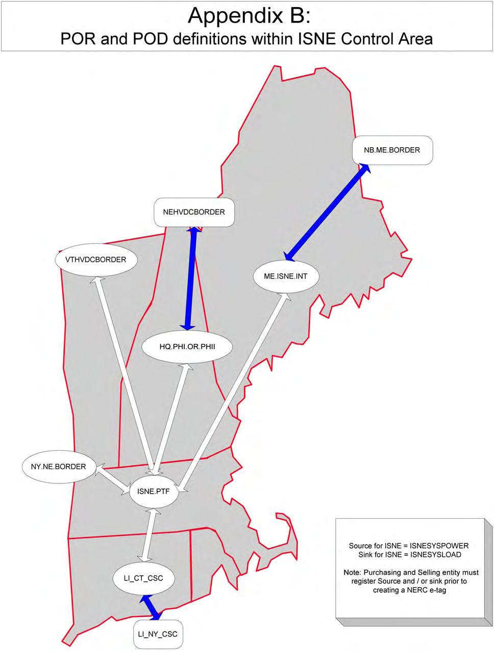
280 13
ATTACHMENT C Methodology to Assess Available Transmission Capability
 Improvement and Power District Revised Sheet No. 107 ATTACHMENT C Methodology to Assess Available Transmission Capability This methodology is excerpted from the report Determination of Available Transfer
PROPOSALFOR INCLUSION OF A TRANSCO INCLUDING ENTERGY WITHIN THE SPP RTO
 PROPOSALFOR INCLUSION OF A TRANSCO INCLUDING ENTERGY WITHIN THE SPP RTO This Proposal outlines the terms and conditions in a proposed Appendix to the Southwest Power Pool's ("SPP's") Membership Agreement
South Carolina Public Service Authority Transmission Reliability Margin Implementation Document (TRMID) April 1, Version 5.0
 April 1, Version 5.0") South Carolina Public Service Authority Transmission Reliability Margin Implementation Document (TRMID) April 1, 2017 Version 5.0 Document Change History Version Date of Change Description of Change 0.0
South Carolina Public Service Authority Transmission Reliability Margin Implementation Document (TRMID) April 1, 2017 Version 5.0 Document Change History Version Date of Change Description of Change 0.0
ISO New England Available Transfer Capability. Implementation Document. Version 1.0
 ISO New England Available Transfer Capability Implementation Document Version 1.0 1 Effective: 04/01/2011 Table of Contents 1. Introduction... 3 2. Transmission Service in the New England Markets... 6
Risk-Based Registration Technical Justification. August 26, 2014
 Risk-Based Registration Technical Justification August 26, 2014 Table of Contents Preface and NERC Mission... iv Executive Summary... v Introduction...1 Background...1 Functional Entities Considered...1
Draft Whitepaper to Platte River Board of Directors
 Draft Whitepaper to Platte River Board of Directors Report on Organized Power Markets RTOs and ISOs Presented for the October 2016 Board Meeting Overview This report on the potential formation of a regional
The Virtues of A Virtual RTO
 The Virtues of A Virtual RTO Jim Mayhew Mirant September 26, 2003 Harvard Electricity Policy Group 1 A Virtual RTO? An Organization That is a RTO in All but Name? Minimum Attributes? Regional Security
System Impact Study and Facilities Study Process Manual For Cleco Power LLC
 System Impact Study and Facilities Study Process Manual For Cleco Power LLC Version 3 March 2010 System Impact Study and Facilities Study Manual for Cleco Power LLC 1.0 Introduction.3 1.1 Purpose.3 1.2
Functional Entity Roles and Responsibilities
 Functional Entity Roles and Responsibilities NWPP MC Phase 3 Operations Integration Work Group 9/28/2014 Page 1 of 13 Table of Contents 1. Purpose... 3 2. Roles and Responsibilities of Functional Entities...
Northwest Power Pool Processes
 Northwest Power Pool Processes Background The Northwest Power Pool membership (NWPP) was founded in 1941 to promote efficient production of electrical energy. The NWPP is the geographic area encompassed
SPP at a Glance. Located in Little Rock. Approximately 600 employees
 SPP at a Glance Located in Little Rock Approximately 600 employees Primary jobs electrical engineering, operations, settlements, and IT 24 x 7 operation Full redundancy and backup site 2 Regulatory Environment
California Independent System Operator Corporation Fifth Replacement Electronic Tariff
 Table of Contents California Independent System Operator Corporation 8. Ancillary Services... 3 8.1 Scope... 3 8.2 Ancillary Services Standards... 4 8.2.1 Determination Of Ancillary Service Standards...
LOAD SERVING ENTITIES PJM REGION
 Intra-PJM Tariffs --> RELIABILITY ASSURANCE AGREEMENT PJM Interconnection, L.L.C. Rate Schedule FERC No. 44 RELIABILITY ASSURANCE AGREEMENT Among LOAD SERVING ENTITIES in the PJM REGION Effective Date:
DRAFT FOR DISCUSSION PURPOSES PROPOSED STRAWMAN PROPOSAL IN RESPONSE TO ORDER 890
 DRAFT FOR DISCUSSION PURPOSES PROPOSED STRAWMAN PROPOSAL IN RESPONSE TO ORDER 890 OVERVIEW AND PURPOSE This strawman proposes enhancements to NYISO s existing reliability and economic planning processes
April 28, Filing of CAISO Rate Schedule No. 90 Docket No. ER
 California Independent System Operator Corporation The Honorable Kimberly D. Bose Secretary Federal Energy Regulatory Commission 888 First Street, NE Washington, DC 20426 April 28, 2017 Re: California
Federal Energy Regulatory Commission Working Paper on Standardized Transmission Service and Wholesale Electric Market Design
 Federal Energy Regulatory Commission Working Paper on Standardized Transmission Service and Wholesale Electric Market Design To enhance competition in wholesale electric markets and broaden the benefits
ATTACHMENT K TRANSMISSION PLANNING PROCESS
 ATTACHMENT K TRANSMISSION PLANNING PROCESS 1.0 Introduction This Attachment K addresses the rights and obligations of Transmission Customers, relevant stakeholders and the Transmission Provider related
Introduction to RRG Drafting Team Proposal
 November 17, 2003 Introduction to RRG Drafting Team Proposal SUMMARY This introduction will review the overall task the RRG drafting team took on, set out the overall guiding principles it used, and describe
Open Access Transmission Tariff ATTACHMENT K
 ATTACHMENT K PART I Introduction The Transmission Provider s (herein referred to as Tacoma Power) local transmission planning process will include open planning meetings that Tacoma Power will conduct
Underfrequency Load Shedding Standard Drafting Team. ERCOT Offices 7620 Metro Center Drive Austin, Texas (512)
") 1) Administrative a) Roll Call Underfrequency Load Shedding Standard Drafting Team August 15, 2007 1 5 p.m. Central Time August 16, 2007 8 a.m. 5 p.m. Central Time August 17, 2007 8 a.m. noon Central Time
1) Administrative a) Roll Call Underfrequency Load Shedding Standard Drafting Team August 15, 2007 1 5 p.m. Central Time August 16, 2007 8 a.m. 5 p.m. Central Time August 17, 2007 8 a.m. noon Central Time
December 20, Amendment to Attachment C to the Southern Companies OATT Docket No. ER14-
 PIYANKA GHOSAL t: (205) 226-3454 f: (205) 488-5839 e: pghosal@balch.com December 20, 2013 BY ELECTRONIC FILING Ms. Kimberly D. Bose, Secretary Mr. Nathaniel J. Davis, Sr., Deputy Secretary Federal Energy
Business Practice Manual for the Transmission Planning Process
 Business Practice Manual for the Transmission Planning Process Order 890 Compliance Version 76.0 September 15,February 11, 2010 TABLE OF CONTENTS Order 890 Compliance... i 1. Introduction... 6 1.1 Purpose
Southwest Power Pool CRITERIA
 Southwest Power Pool CRITERIA LATEST REVISION: April 28, 2015 FOREWORD... i INTRODUCTION... ii 1.0 LOAD AND ENERGY FORECASTS...1-1 2.0 CAPACITY MARGIN...2-1 2.1 Definitions...2-1 2.1.1 Load Serving Member...2-1
Business Practice Manual for Reliability Requirements. Version 34
 Business Practice Manual for Reliability Requirements Version 34 Last Revised: January 1, 2009July 28, 2010 Approval History Approval Date: 3/27/09 Effective Date: 3/31/09 BPM Owner: Chetty Mamandur BPM
the Real-Time Market will be based on the system marginal costs produced by the Real-Time
 17.1 LBMP Calculation The Locational Based Marginal Prices ( LBMPs or prices ) for Suppliers and Loads in the Real-Time Market will be based on the system marginal costs produced by the Real-Time Dispatch
ANEACIÓN DE SISTEMAS DE ENERGÍA FLEXIBLE.
 November 2007 BGE VISIÓN DE LA PLANEACIÓN DE SISTEMAS DE ENERGÍA FLEXIBLE. January 4, 2008 December 12 and 13 2012. Medellin, Colombia Page 1 Presentation Outline Introduction Vision and context for the
Periodic Review Template INT Implementation of Interchange
 INT-009-2.1 Implementation of Interchange Executive Summary The Subject Matter Expert (SME) stakeholder team completed an initial comprehensive review of INT- 009-2.1 Implementation of Interchange. The
Business Practices for. Schedule 21-ES. (Modifications Issued on August 11, 2016)
") (Modifications Issued on August 11, 2016) 1 List of Contents Introduction Purpose of Document Overview of Transmission Services in New England Definitions Applicable Schedules Services Applicable to these
(Modifications Issued on August 11, 2016) 1 List of Contents Introduction Purpose of Document Overview of Transmission Services in New England Definitions Applicable Schedules Services Applicable to these
Outage Coordination Training MISO Training
 MISO Last material update: 05/19/2015 Course Content and Disclaimer 2 1 2 3 4 Course Description This course will review MISO's outage study processes and the coordination opportunities with TOs and MPs.
 ORLANDO UTILITIES COMMISSION Open Access Transmission Tariff Original Sheet 91 SCHEDULE 7 Long-Term Firm and Short-Term Firm Point-To-Point Transmission Service The Transmission Customer shall compensate
Load Serving Entity Definition Refinement Draft Final Proposal
 Updated: September 21, 2016 Table of Contents 1. Executive Summary... 4 2. Scope of Initiative... 6 3. Changes to this proposal... 6 4. Stakeholder Engagement... 7 5. Background... 8 Allocation of Congestion
INDEPENDENT SYSTEM OPERATORS (VI + Access Rules vs. ISO vs. ITSO)
") INDEPENDENT SYSTEM OPERATORS (VI + Access Rules vs. ISO vs. ITSO) Paul L. Joskow September 28, 2007 ALTERNATIVE SYSTEM OPERATOR MODELS System operator (SO) is vertically integrated utility (G+T) Functional
INDEPENDENT SYSTEM OPERATORS (VI + Access Rules vs. ISO vs. ITSO) Paul L. Joskow September 28, 2007 ALTERNATIVE SYSTEM OPERATOR MODELS System operator (SO) is vertically integrated utility (G+T) Functional
California Independent System Operator Corporation Fifth Replacement Electronic Tariff
 Table of Contents Appendix N... 2 Pseudo-Tie Protocol... 2 1. Pseudo-Ties of Generating Units to the CAISO Balancing Authority Area... 2 1.1 Consistency with NERC/WECC Requirements... 2 1.2 CAISO Operating,
BUSINESS PRACTICE MANUAL CHANGE MANAGEMENT CAISO RESPONSE TO APPEALS
 BUSINESS PRACTICE MANUAL CHANGE MANAGEMENT CAISO RESPONSE TO APPEALS I. Introduction The CAISO followed its business practice manual change management process 1 and submitted proposed revision request
A. Introduction Balancing Authority Reliability Coordinator Transmission Operator. 5. Effective Date:
 A. Introduction 1. Title: Emergency Operations 2. Number: EOP-011-1 3. Purpose: To address the effects of operating Emergencies by ensuring each Transmission Operator and Balancing Authority has developed
Wind Power Transmission Case Studies Project National Wind Coordinating Committee
 National Wind Coordinating Committee Wind Power Transmission Case Studies Project National Wind Coordinating Committee September 2000 Wind Power Transmission Case Studies Project National Wind Coordinating
3. RELATIONSHIP BETWEEN ISO AND PARTICIPATING TOs. Each Participating TO shall enter into a Transmission Control Agreement with the
 FERC ELECTRIC TARIFF First Revised Sheet No. 121 ORIGINAL VOLUME NO. I Replacing Original Sheet No. 121 3. RELATIONSHIP BETWEEN ISO AND PARTICIPATING TOs. 3.1 Nature of Relationship. Each Participating
UNITED STATES OF AMERICA BEFORE THE FEDERAL ENERGY REGULATORY COMMISSION. NORTH AMERICAN ELECTRIC ) Docket No. RD13- RELIABILITY CORPORATION )
 Docket No. RD13- RELIABILITY CORPORATION )") UNITED STATES OF AMERICA BEFORE THE FEDERAL ENERGY REGULATORY COMMISSION NORTH AMERICAN ELECTRIC ) Docket No. RD13- RELIABILITY CORPORATION ) PETITION OF THE NORTH AMERICAN ELECTRIC RELIABILITY CORPORATION
UNITED STATES OF AMERICA BEFORE THE FEDERAL ENERGY REGULATORY COMMISSION NORTH AMERICAN ELECTRIC ) Docket No. RD13- RELIABILITY CORPORATION ) PETITION OF THE NORTH AMERICAN ELECTRIC RELIABILITY CORPORATION
NPCC Regional Reliability Reference Directory # 9 Verification of Generator Gross and Net Real Power Capability
 NPCC Regional Reliability Reference Directory # 9 Task Force on Coordination of Operations Revision Review Record: December 22, 2008 December 28, 2011 Adopted by the Members of the Northeast Power Coordinating
ISO New England - ISO New England Inc. Transmission, Markets and Services Tariff
 ATTACHMENT K REGIONAL SYSTEM PLANNING PROCESS TABLE OF CONTENTS 1. Overview 2. Planning Advisory Committee 2.1 Establishment 2.2 Role of Planning Advisory Committee 2.3 Membership 2.4 Procedures (a) Notice
155 FERC 61,111 UNITED STATES OF AMERICA FEDERAL ENERGY REGULATORY COMMISSION
 155 FERC 61,111 UNITED STATES OF AMERICA FEDERAL ENERGY REGULATORY COMMISSION Before Commissioners: Norman C. Bay, Chairman; Cheryl A. LaFleur, Tony Clark, and Colette D. Honorable. Puget Sound Energy,
Load Forecasting Manual
 MANUAL 6 Load Forecasting Manual September 2013 Version: 4.0.1 Effective Date: 09/11/2013 Committee Acceptance: 09/01/2010 This document was prepared by: NYISO Reliability & Security New York Independent
Periodic Review Template INT Evaluation of Interchange Transactions
 INT-006-4 Evaluation of Interchange Transactions Executive Summary The Subject Matter Expert (SME) stakeholder team completed an initial comprehensive review of INT- 006-4 Evaluation of Interchange Transactions.
PJM Manual 14A: New Services Request Process Revision: 20 Effective Date: October 1, Prepared by Interconnection Planning Department
 PJM Manual 14A: New Services Request Process Revision: 20 Effective Date: October 1, 2017 Prepared by Interconnection Planning Department PJM 2017 Table of Contents Table of Contents Table of Exhibits...7
PER Operations Personnel Training
 A. Introduction 1. Title: Operations Personnel Training 2. Number: PER-005-2 3. Purpose: To ensure that personnel performing or supporting Real-time operations on the Bulk Electric System are trained using
142 FERC 61,070 UNITED STATES OF AMERICA FEDERAL ENERGY REGULATORY COMMISSION
 142 FERC 61,070 UNITED STATES OF AMERICA FEDERAL ENERGY REGULATORY COMMISSION Before Commissioners: Jon Wellinghoff, Chairman; Philip D. Moeller, John R. Norris, Cheryl A. LaFleur, and Tony T. Clark. Southwest
MOD Data for Power System Modeling and Analysis
 MOD-032-1 Data for Power System Modeling and Analysis A. Introduction 1. Title: Data for Power System Modeling and Analysis 2. Number: MOD-032-1 3. Purpose: To establish consistent modeling data requirements
Frequently Asked Questions August 2013
 Frequently Asked Questions August 2013 General What is the Bulk-Power System or Bulk Electric System? NERC defines the Bulk-Power System as the electricity power generation facilities combined with the
LES Standards of Conduct Implementation and Compliance Procedures
 LES Standards of Conduct Implementation and Compliance Procedures 1040 O Street, P.O. Box 80869 Lincoln, NE 68501-0869 p: 402.475.4211 LES.com Lincoln Electric System Posted Update: April 21, 2017 I. OVERVIEW
CIP Cyber Security Security Management Controls
 A. Introduction 1. Title: Cyber Security Security Management Controls 2. Number: CIP-003-5 3. Purpose: To specify consistent and sustainable security management controls that establish responsibility and
Demand Response and Scarcity Pricing
 Item #/ Check When Complete Demand and Scarcity Pricing Begin End Category Sub-Category Order 719 Summary Draft Status SPP Notes References Assignment 41 47 63 Demand Allow DR to provide ancillary services
Loads and Resources Methods and Assumptions
 Loads and Resources Methods and Assumptions WECC Staff September 2014 155 North 400 West, Suite 200 Salt Lake City, Utah 84103-1114 Loads and Resources Methods and Assumptions ii Contents Purpose... 1
Regional Cooperation of US States on Electric Transmission Issues
 Regional Cooperation of US States on Electric Transmission Issues William H. Smith, Jr. Executive Director Organization of MISO States [Midwest Independent System Operator] NARUC Exchange Program: Albania
Vector Pipeline L.P. Original Sheet No. 30 FERC Gas Tariff First Revised Volume No. 1 v0.0.0 RATE SCHEDULE FT-1 FIRM TRANSPORTATION SERVICE
 Vector Pipeline L.P. Original Sheet No. 30 1. AVAILABILITY RATE SCHEDULE FT-1 FIRM TRANSPORTATION SERVICE This FT-1 Rate Schedule is available to any party (hereinafter called "Shipper"), for firm transportation
STATEMENT OF WORK. Use the PJM AFC / ATC tool to calculate and post ATC values to the ComEd (MAIN) OASIS.
 OASIS.") STATEMENT OF WORK SCOPE OF WORK PJM will provide tariff administration services as follows: Administration of the (MAIN) node, analysis, evaluation, granting / rejection of transmission service and response
STATEMENT OF WORK SCOPE OF WORK PJM will provide tariff administration services as follows: Administration of the (MAIN) node, analysis, evaluation, granting / rejection of transmission service and response
MOD Steady-State and Dynamic System Model Validation
 MOD-033-1 Steady-State and Dynamic System Model Validation A. Introduction 1. Title: Steady-State and Dynamic System Model Validation 2. Number: MOD-033-1 3. Purpose: To establish consistent validation
Standard TPL Transmission System Planning Performance Requirements
 A. Introduction 1. Title: Transmission System Planning Performance Requirements 2. Number: TPL-001-4 3. Purpose: Establish Transmission system planning performance requirements within the planning horizon
Energy Markets - The Basics
 Disclaimer This training presentation is provided as a reference for preparing for the PJM Certification Exam. Note that the following information may not reflect current PJM rules and operating procedures.
Date of Request for Comment: April 7, 2017 Period of Comment: April 7, 2017 through May 5, 2017
 Market Participant Comments and AESO Replies Matrix Proposed Amended Section 304.3, Wind and Solar Power Ramp Up Management ( amended Section 304.3 ) Date of Request for Comment: April 7, 2017 Period of
ATTACHMENT P. Transmission Planning Process
 ATTACHMENT P Transmission Planning Process Overview of Western s Transmission Planning Processes The Western Area Power Administration (Western) is a Federal agency under the Department of Energy that
UNITED STATES OF AMERICA FEDERAL ENERGY REGULATORY COMMISSION
 103 FERC 61,270 UNITED STATES OF AMERICA FEDERAL ENERGY REGULATORY COMMISSION Before Commissioners: Pat Wood, III, Chairman; William L. Massey, and Nora Mead Brownell. Entergy Services, Inc. Docket No.
Utility Scale Integration of Wind and Solar Power
 Utility Scale Integration of Wind and Solar Power Charles Reinhold WestConnect Project Manager Southwest Renewable Energy Conference Flagstaff, AZ Presentation Overview WestConnect Background Area Control
Generation Capacity Mechanisms and Resource Adequacy Planning
 Generation Capacity Mechanisms and Resource Adequacy Planning Jennifer Heintz Public Service Commission of the State of Missouri February 7, 2013 Abu Dhabi, UAE Electricity Markets in the U.S. and Canada
Industry Webinar. Project Geomagnetic Disturbance Mitigation. Frank Koza, PJM Interconnection July 27, 2017
 Industry Webinar Project 2013-03 Geomagnetic Disturbance Mitigation Frank Koza, PJM Interconnection July 27, 2017 Agenda Administrative Items Review of TPL 007 1 Benchmark GMD Event Directed Revisions
Modeling Transmission Outages in the CRR Network Model
 Modeling Transmission Outages in the CRR Network Model Lorenzo Kristov Market & Product Development Dept. CRR Stakeholder Meeting June 14, 2007 Outline of Today s Discussion CRR Revenue Adequacy Timing
Periodic Review Template INT Dynamic Transfers
 INT-004-3.1 Dynamic Transfers Executive Summary The Subject Matter Expert (SME) stakeholder team completed an initial comprehensive review of INT- 004-3.1 Dynamic Transfers. The SME stakeholder team finds
Methodology for Determining and Communicating System Operating Limits for the Planning Horizon (FAC-010 & -014) Revision Log
 Revision Log") Revision Log Page 2 of 13 Revision or Change Number Effective Date Affected Page Numbers Description of Revision/Change 0000 03-26-2011 All Converted TPD document to SPP format 0001 03-26-2012 All Annual
Revision Log Page 2 of 13 Revision or Change Number Effective Date Affected Page Numbers Description of Revision/Change 0000 03-26-2011 All Converted TPD document to SPP format 0001 03-26-2012 All Annual
LEER/TLR 5 Drill Procedure General Coordination Procedures and Drill Scenario
 LEER/TLR 5 Drill Procedure General Coordination Procedures and Drill Scenario General The participants of the Lake Erie Emergency Redispatch (LEER) procedure will perform drills of various scenarios of
PJM Manual 21: Rules and Procedures for Determination of Generating Capability Revision: 12 Effective Date: January 1, 2017
 PJM Manual 21: Rules and Procedures for Determination of Generating Capability Revision: 12 Effective Date: January 1, 2017 Prepared by System Planning Department PJM 2017 Table of Contents Table of Contents
Presentation on Draft SCED RFP
 Presentation on Draft SCED RFP Pre-RFP Release Conference October 9, 2014 Presenters: Eric Espenhorst, Seattle City Light Erin Apperson, Puget Sound Energy Robb Davis, BPA Roger Bentz, BPA Kevin Holland,
Critical Actions Necessary for Effective Market Monitoring
 Critical Actions Necessary for Effective Market Monitoring Draft Comments of Anjali Sheffrin, Ph.D. Dept of Market Analysis, California ISO FERC RTO Workshop, October, 200 Mr. Chairman and Commissioners,
Load Granularity Refinements Issue Paper
 Load Granularity Refinements Issue Paper September 22, 2014 Table of Contents I. Introduction... 3 II. Background... 3 III. Scope of Initiative and Plan for Stakeholder Engagement... 4 IV. FERC s Reasons
Committed Offer: Offer on which a resource was scheduled by the Office of the Interconnection for a particular clock hour for the Operating Day.
 Proposed Tariff Revisions Attachment K-Appendix and Schedule 1 of the Operating Agreement Generator Offer Flexibility Senior Task Force Revisions Related To Make-Whole and Lost Opportunity Cost Payments
Transmission Planning Protocol of Western Electricity Coordinating Council s Transmission Expansion Planning Policy Committee
 D R A F T Transmission Planning Protocol of Western Electricity Coordinating Council s Transmission Expansion Planning Policy Committee 1 Purpose and Objectives This Protocol governs the transmission planning
TPL Transmission System Planned Performance for Geomagnetic Disturbance Events
 A. Introduction 1. Title: Transmission System Planned Performance for Geomagnetic Disturbance Events 2. Number: TPL-007-1 3. Purpose: Establish requirements for Transmission system planned performance
Dynamic Transfers Revised Draft Final Proposal
 Dynamic Transfers Revised Draft Final Proposal Provided in Support of 2009-2011 Stakeholder Process to Consider Expansion of Dynamic Transfer Services in ISO Tariff Revised February 18, 2011 CAISO/M&ID/Dynamic
AESO Practices for System Access Service. May 31, 2013
 AESO Practices for System Access Service May 31, 2013 Table of Contents 1 Purpose... 3 2 Introduction... 3 3 Practices for System Access Service... 4 3.1 Conditions for System Access Service... 4 3.2 Rationale
PLATTE RIVER POWER AUTHORITY OPEN ACCESS TRANSMISSION TARIFF. May 1, 2009
 PLATTE RIVER POWER AUTHORITY OPEN ACCESS TRANSMISSION TARIFF May 1, 2009 Original Sheet No.1 TABLE OF CONTENTS I. COMMON SERVICE PROVISIONS... 8 1 Definitions... 8 1.1 Ancillary Services... 8 1.2 Annual
UNMIK REGULATION NO. 2004/22 ON THE PROMULGATION OF A LAW ADOPTED BY THE ASSEMBLY OF KOSOVO ON ELECTRICITY
 UNITED NATIONS United Nations Interim Administration Mission in Kosovo UNMIK NATIONS UNIES Mission d Administration Intérimaire des Nations Unies au Kosovo UNMIK/REG/2004/22 30 June 2004 REGULATION NO.
Introduction to the Energy Imbalance Market (EIM Module 1)
") Introduction to the Energy Imbalance Market (EIM Module 1) Cynthia Hinman Lead Client Trainer Webinar July 25, 2013 The information contained in these materials is provided for general information only
Introduction to the Energy Imbalance Market (EIM Module 1) Cynthia Hinman Lead Client Trainer Webinar July 25, 2013 The information contained in these materials is provided for general information only
Operating Procedure PURPOSE... 1
 Table of Contents PURPOSE... 1 1. RESPONSIBILITIES... 2 2. SCOPE/APPLICABILITY... 2 2.1. Background... 2 2.2. Scope/ Applicability... 2 3. PROCEDURE DETAIL... 3 3.1. Order of Steps... 3 3.2. Restricted
May 1, The Honorable Kimberly D. Bose Secretary Federal Energy Regulatory Commission 888 First Street NE Washington, DC 20426
 May 1, 2017 The Honorable Kimberly D. Bose Secretary Federal Energy Regulatory Commission 888 First Street NE Washington, DC 20426 Re: Southwest Power Pool, Inc., Docket No. ER17- Submission of Network
NERC Organization Standards: What are they????
 NERC Organization Standards: What are they???? Northeast Power Coordinating Council General Meeting September 19, 2002 Stanley E. Kopman Director, Planning and Compliance Northeast Power Coordinating Council
CAISO s Flexible Resource Adequacy and Must Offer Obligation Phase 2 Revised Straw Proposal Public Generating Pool and Public Power Council Comments
 CAISO s Flexible Resource Adequacy and Must Offer Obligation Phase 2 Revised Straw Proposal Public Generating Pool and Public Power Council Comments May 22, 2017 Public Generating Pool (PGP) and Public
Standard MOD Verification of Models and Data for Turbine/Governor and Load Control or Active Power/Frequency Control Functions
 Standard Development Roadmap This section is maintained by the drafting team during the development of the standard and will be removed when the standard becomes effective. Development Steps Completed:
Exploring the Impacts of California s Renewable Portfolio Standard
 Exploring the Impacts of California s Renewable Portfolio Standard System Planning Committee April 2010 Table of Contents Purpose... 1 Vocabulary... 1 System Planning Committee s Initial Assessment...
Standard BAL-502-RFC-02
 A. Introduction 1. Title: Planning Analysis, Assessment and Documentation 2. Number: BAL-502-RFC-02 3. Purpose: To establish common criteria, based on one day in ten year loss of Load expectation principles,
2. Market Operations Overview
 2. Market Operations Overview 2.5 Market Information This section summarizes and describes the common information that is used by the Day-Ahead and Real-Time processes. 2.5.1 Resource Static Data Static
LOLE is expressed as hours per year with the usual target criteria being (0.1 days/year) or 1- day in 10-years MISO Tariff: Module E-1 - The
 or 1- day in 10-years MISO Tariff: Module E-1 - The") 1 2 3 4 LOLE is expressed as hours per year with the usual target criteria being (0.1 days/year) or 1- day in 10-years MISO Tariff: Module E-1 - The Transmission Provider will calculate and post the Planning
1 2 3 4 LOLE is expressed as hours per year with the usual target criteria being (0.1 days/year) or 1- day in 10-years MISO Tariff: Module E-1 - The Transmission Provider will calculate and post the Planning
January 27, The Honorable Kimberly D. Bose Secretary Federal Energy Regulatory Commission 888 First Street, NE Washington, DC 20426
 California Independent System Operator Corporation The Honorable Kimberly D. Bose Secretary Federal Energy Regulatory Commission 888 First Street, NE Washington, DC 20426 January 27, 2017 Re: California
Energy Imbalance Market Year 1 Enhancements Phase 2. Draft Final Proposal
 Energy Imbalance Market Year 1 Enhancements Phase 2 Draft Final Proposal September 8, 2015 Energy Imbalance Market Year 1 Enhancements Phase 2 Draft Final Proposal Table of Contents 1 Introduction... 3
INTEGRATED TRANSMISSION PLANNING MANUAL
 INTEGRATED TRANSMISSION PLANNING MANUAL Published on July 20, 2017 Pending FERC approval of Tariff language By SPP staff REVISION HISTORY DATE OR VERSION NUMBER AUTHOR CHANGE DESCRIPTION COMMENTS 10/13/2010
ISO-NE FCM Capacity Market Design Scott M. Harvey. October 9, 2007
 ISO-NE FCM Capacity Market Design Scott M. Harvey October 9, 2007 Summary The ISO-NE FCM capacity market design embodies many improvements over the prior ISO-NE capacity market. Five of these improvements
Introduction to the PJM Markets
 Introduction to the PJM Markets PJM 2015 1 Objectives Students will be able to: Describe some of the basic functions of PJM PJM 2015 The History of PJM EKPC joins PJM 2013 PJM 2015 3 Our Responsibility
Report on 2011 NPCC Culture of Compliance Survey Initiative
 Report on 2011 NPCC Culture of Compliance Survey Initiative Development In September 2010, NPCC Staff began an initiative that would attempt to identify a registered entity s Culture of Compliance. NPCC
Revenues from Ancillary Services and the Value of Operational Flexibility
 Revenues from Ancillary Services and the Value of Operational Flexibility October 31, 2002 LCG Consulting The Issue Research Highlights In a restructured electricity industry, markets govern the operation
December 11, 2013 VIA ELECTRONIC FILING
 VIA ELECTRONIC FILING The Honorable Kimberly D. Bose Secretary Federal Energy Regulatory Commission 888 First Street, N.E. Washington, D.C. 20426 Re: Southwest Power Pool, Inc., Docket No. ER14- -000 Compliance
Southern California Edison Company SOUTHERN CALIFORNIA EDISON COMPANY WHOLESALE DISTRIBUTION ACCESS TARIFF
 SOUTHERN CALIFORNIA EDISON COMPANY WHOLESALE DISTRIBUTION ACCESS TARIFF Original Sheet No. TABLE OF CONTENTS. Applicability.... Definitions.... Nature of Distribution Service.... Term.... Distribution
Standard IRO Reliability Coordinator Data Specification and Collection
 A. Introduction 1. Title: Reliability Coordinator Data Specification and Collection 2. Number: IRO-010-2 3. Purpose: To prevent instability, uncontrolled separation, or Cascading outages that adversely
Eastern Wind Integration and
 Eastern Wind Integration and Transmission Study Overview NCSL Transmission Policy Institute Denver, CO June 17-18, 2010 Dave Corbus National Renewable Energy Laboratory NREL is a national laboratory of