HDI 2200 Choke Position Indicator
|
|
|
- Asher Stevens
- 6 years ago
- Views:
Transcription
1 HDI 2200 Choke Position Indicator Operations and Maintenance Manual Rev or
2 TABLE OF CONTENTS SECTION 1 SECTION 2 SECTION 3 SECTION 4 SECTION 5 SECTION 6 Systems General Information: 1.1 General Information: 1.2 Unpacking and Inspection: 1.3 Precautionary Information: 1.4 Personnel Qualifications: System Description: 2.1 System Description General: 2.2 System Components: Choke Position Indicator: Choke Position Sensors: Cables 2.3 System Capacities: Choke Position Indicators: 2.4 System Options Remote Display: /20 ma Output: VDC Output: Installation: 3.1 Components Location: Console and Sensors: Cables: 3.2 Mounting Hardware 3.3 Potentiometer Assembly & Installation General Assembly Display Installation Cables Theory of Operation: 4.1 Choke Position Systems: Calibration: 5.1 Choke Position Systems: Corrective Maintenance: 6.1 Choke Position Systems: 6.2 Choke Position Systems Battery Replacement: 6.3 Adjustment Preparation 2
3 SECTION 7 SECTION 8 Preventative Maintenance 7.1 Choke Systems: Warranty 3
4 SECTION 1 Systems General Information: 1.1 General Information: This manual describes the installation operation and maintenance of the HDI System #2200 Choke Position Indicating System. This manual shall provide the user with information necessary to properly utilize the Choke Position Indicating System. Included in this manual are all the necessary procedures to install and maintain this Choke Position Indicating System Instrumentation properly. 1.2 Unpacking and Inspection: Upon receipt of the equipment, assure all items are accounted for on the packing list. If any items are missing, immediately inform the freight forwarder. Inspect all items for damage. If any items are damaged immediately inform the freight forwarder and Houston Digital Instruments, Inc. 1.3 Precautionary Information: Assure all directions on the packages are followed during unpacking and handling. 1.4 Personnel Qualifications: This equipment requires experienced personnel to handle, install and maintain. HDI offers a technical training school on their premises if the Customer desires. 4
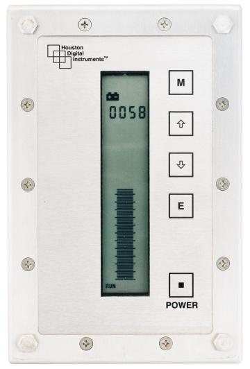
5 SECTION 2 Systems Description: 2.1 Systems Description: The HDI System #2200 is a Electronic Choke Position Indicating System. The system consists of an electronic potentiometer housed in a stainless steel tube that is located in a stainless steel housing. The assembly is adjustable inside the housing to assure the sensor is located properly. The housing(s) are constructed to adapt to a variety of choke(s). The display is a liquid crystal display (LCD), which includes both a three digit numerical display (for accuracy) and a bargraph (101 segments) representation (for trend).the electronic bar graph display indicates choke position from closed to open, percent and in 1/8 graduations. 2.2 System Components: Choke Position Indicators: Two (2) Choke Position Indicators with numeric and Bar Graph displays (for dual display systemotherwise one indicator) Choke Position Sensors: Two (2) Choke Position Housings with HDI provided position sensors and mounting systems (for a dual system only. Single systems have a single sensor or transducer) Cables: All interconnecting cables supplied by HDI. 2.3 System Capacities: Choke Position Indicators: Choke Position Indicators are rated for 0 to 100 percent or in oneeighth graduations open. 2.4 System Options: Custom designed systems will include, per the customers' request or customers' specifications, certain options required to meet offshore area classifications or specific customer requirements. Each system of this type will be designed to meet specific requirements or classifications and is therefore unique and as such goes beyond the scope of this publication. Barriers or explosion proof junction boxes are not required as the system has been certified intrinsically safe by the Canadian Standards Association (CSA). The following are common examples that may be encountered or requested by customers. HDI offers the following options at additional cost Remote Display: Remote displays may be provided to allow secondary indicators at an alternate location at the customer s request /20 ma Output: HDI offers as an option, a signal current loop providing a 4/20 ma remote output that may be used for chart recorder inputs and/or datalogging. 5
6 VDC Output: HDI offers as an option, a signal providing a 01Vdc remote output that may be used by the customer for chart recorder inputs and/or datalogging. This is a factory installed option and does not require calibration. 6
7 SECTION 3 Installation: 3.1 Components Location: Control Head and Sensors: The Control Head and Sensors are to be mounted by the Customer at the locations deemed most suitable for such equipment. The system transducer (POTENTIOMETER) comes from the factory as a complete assembly and only requires mounting of the transducer housing using standard practices for such installations Cables: All wire lengths from the Panel to the sensors shall be supplied by the customer. 3.2 Mounting Hardware: Provided by HDI, custom fit ups available as option by HDI. 3.3 Choke Position Sensor Assembly and Installation: Assembly General: The Choke Position Potentiometer and mounting brackets are provided to replace an existing pneumatic regulator choke position system presently in use. This assembly is designed to mount in the original choke position enclosure utilizing the existing hole patterns and mounting hardware. Remove the existing choke position ass'y. Install the new stainless steel housing and potentiometer ass'y with mounting brackets with the existing mounting hardware. The potentiometer shaft must be threaded into the existing choke shaft via the adjustment stud. Leave the potentiometer mounting brackets loose for adjustment. With the choke body in the fully closed position, adjust the potentiometer ass'y to allow 1/8 to 1/4" compression of the shaft into the potentiometer housing and tighten the locknut and the mounting brackets mounting screws. Assure the potentiometer does not bottom out inside its' own housing. Proceed to Calibration Choke Position Display: The system gauge is designed to be installed in a 7.25 x 4.25 cutout hole in the panel. Both the 90 degree and 120 degree bolt patterns are designed into the gauge and all applicable hardware is included. Remove the #10 elastic stopnuts from the 10 X 32 screws, drop the gauge in the appropriate hole and replace the stopnuts Cables The system comes complete with wire and connectors made to the customer s specifications. Simply route the wire from the transducer to the gauge using standard practices, connect the cables to the transducer and gauge, and tighten the collars. SECTION 4 Theory of Operation: 7
8 4.1 Choke Positioning Systems: The major components of this system consist of the Control Head, Transducer, and Power Source. The Power Source is a 3.6 potted (replaceable) Battery Pack. The Power Pack supplies power to the Control Head via the power cable. The Control Head then supplies the excitation to the Transducer. The Transducer is a sliding potentiometer that measures its own extension and compression. This Choke Position information is returned to the Control Head. The Control Head then converts the voltage to digital information which is then used to drive a 101 segment Bar Graph display, oneeighth division Bar Graph, and digital display. The Choke Position Indicator does not require any warm up period. Turning the system off when not in use will greatly extend battery life (Power OFF by pressing the Mode Select Button and then pressing the Power Button.) The Choke Position Indicator contains these operator initiated functions: Mode Select Button UP ARROW 100% Calibration Select Button DOWN ARROW 0% Calibration Select Button Selects calibration and power on/off Modes. Allows for calibration at open choke position. Allows for calibration at closed choke position. Enter Select Button Enters Mode and Calibration Selections Power ON/OFF. Power on/off switch. Power ON: Press Power button once (Unit performs selftest, all display segments turn on) Power OFF: Press MODE button once (the RUN indicator should TURN OFF) then press the POWER button within.5 sec. NOTE: (if the RUN indicator does not TURN OFF, press the MODE button again) 8
9 SECTION 5 CALIBRATION: 5.1 Choke Position System: THIS DEVICE IS CALIBRATED FROM THE CHOKE POSITION INDICATOR (Display Panel) (SEE Section 4) Setting Closed Position Level 1. Once the installation is complete the choke should be closed completely. 2. Apply power to device by pressing the POWER button. 3. Choke Position Indicator will perform self test for approximately 5 seconds during which time all LCD displays will be active. 4. After self test, the display will be in the run/active mode. ( RUN indicator will appear at the lower left side of the LCD display) 5. With Choke completely CLOSED, press the MODE button. (RUN indicator will turn OFF) 6. Press Down button within 2 secs. (Now in calibration mode) 7. The down arrow and a four digit number will appear at the top of the LCD display. 8. Press the Enter button. (Accepts the low / closed set point position, unit returns to RUN mode) 9. The closed position level is now set, and the three digit display should read Setting Open Position Level 1. Open the Choke completely. 2. With Choke completely open press MODE button. (RUN indicator will turn OFF) 3. Press UP button within 2 secs. (Now in calibration mode) 4. the up arrow and a four digit number will appear at the top of the LCD display. 5. Press the Enter button. (Accepts the low / closed set point position, unit returns to RUN mode) 6. The closed position level is now set, and the three digit display should read Unit is now fully calibrated. 9
10 SECTION 6 MAINTENANCE 6.1 Choke Position System The HDI 2200 is a digital electronic gauge designed specifically for Oilfield applications. Allows for calibation at open choke position.only minor adjustments should be required during instrument should be recalibrated every two (2) years, after a battery change or any change in wiring from the sensor to the gauge. One (1) to two (2) hours per gauge This system does not require any user maintenance. 6.2 Choke Position Systems Battery Replacement: Remove the Canon Connector from the case. Remove the four (4) 1/4"20 hex screws, nuts and washers and remove the unit from the panel. Remove the 10X32 flat head phillips screws from the front of the unit. Remove the front plate, trim ring plexiglass and gasket. Be careful not to damage the gasket. Lay the gauge to the side and assure it does not get damaged. The battery is secured by velcro to the case. Pull apart the connector that connects the battery to the display. A large screwdriver carefully placed under the battery will pry the battery out of the case. Insert the battery in the case to the velcro. Reconnect the connectors. Replace the display. Connect the canon connector to the rear of the case. Test the system. If the system operates properly reassemble and remount in the reverse order from above. Check Calibration and recalibrate per Section V. 6.3 Tools Required for Calibration and Service: THIS STEP IS NOT NECESSARY WHEN MAKING MINOR ADJUSTMENTS TO A PREVIOUSLY CALIBRATED SYSTEM 1. Screwdriver, Phillips. 2. Screwdriver, Flat Blade. 3. Nutdriver, 3/8". 4. Nutdriver, 7/16". Note: All required tools may be purchased from Houston Digital Instruments, Inc. 10
11 SECTION 7 Preventative Maintenance: 7.1 Choke Systems: This system does not require any user maintenance. The battery pack will need to be replaced on average every two (2) years. Note: The system calibration should be checked after battery replacement. 11
12 SECTION 8 Warranty: Houston Digital Instruments, Inc. (HDI) warrants for a period of one year from the date of shipment, HDI's manufactured products to the extent that HDI will replace those parts having defects in material or workmanship when used for the purpose or specification HDI recommends. HDI will replace or repair, as it deems necessary, any products covered by this warranty, after HDI's examination discloses to its satisfaction, that in fact the products are defective and an adjustment is required. If an adjustment is required, the amount of the adjustment is the net sales price of the defective product. No allowances shall be made for labor or expenses of repairing defective products or damage resulting from same. All products accepted under the provisions of this warranty shall be shipped prepaid to HDI and returned to the customer prepaid by HDI. All products not accepted under the provisions of this warranty shall be shipped prepaid to HDI and returned freight collect. HDI shall not be responsible for repair or replacement of products, resulting from improper handling, storage, installation, misuse, negligence, or use in a manner contrary to the recommendations of HDI. HDI warrants only the products which it sells of Other Manufacturers to the extent of their warranties. All warranty claims shall be made in writing to the nearest HDI office or authorized factory representative. HDI makes no other warranty of any kind, expressed or implied, and all implied warranties of merchantability or fitness for a particular purpose which exceed HDI's aforestated obligation are hereby disclaimed by HDI and excluded from this warranty. This warranty is non transferable and HDI shall not be liable for any damage, injury, loss to property or persons resulting from the use of any HDI's products or equipment whether such damage, injury or loss results from, or is caused by: manner of use, defects in materials or workmanship or otherwise. 12
13
14 TM Mounting Pattern for HDI 2200 Series Choke Position Indicators (Gauge) REV. DESCRIPTION DATE D D 4X R.125 C C B B X ø.313 A AutoCAD PROPRIETARY NOTE THIS DOCUMENT CONTAINS INFORMATION CONFIDENTIAL AND PROPRIETARY TO HOUSTON DIGITAL INSTRUMENTS AND SHALL NOT BE REPRODUCED OR TRANSFERRED TO OTHER DOCUMENTS OR DISCLOSED TO OTHERS OR USED FOR ANY PURPOSE OTHER THAN THAT FOR WHICH IT WAS OBTAINED WITHOUT THE EXPRESSED WRITTEN CONSENT OF HOUSTON DIGITAL INSTRUMENTS ALL DIMENSIONS ARE IN INCHES UNLESS OTHERWISE SPECIFIED. TOLERANCES ARE: DECIMAL.XXX ±.010.XX ±.02.X ±.03 REMOVE ALL BURRS & SHARP EDGES Directors Row Houston TX (713) F:(713) MATERIAL: SEE NOTE X FRACTIONAL ±1/32 FINISH: ANGULAR SEE NOTE X ±1/2 APPROVALS DRAWN RENEE DESIGNED ENGINEER MFG MGMT NEXT ASSEMBLY DO NOT SCALE DRAWING 4402 DATE CUTOUT MODEL 2200 CHOKE POSITION INDICATOR DRAWING NO REV. HDI2200M875CUTOT SCALE Houston Digital Instruments FULL SHEET OF 1 1 A
Wash Down Duty Non-Contact Sensor
 Wash Down Duty Non-Contact Sensor Instruction Manual Models WDDC1-020/040/060/080/100 WDDC2-020/040/060/080/100 WDDV1-020/040/060/080/100 WDDV2-020/040/060/080/100 Table of Contents 1. General Description.....................................
DRYWALL DOLLY 900 LB. CAPACITY
 DRYWALL DOLLY 900 LB. CAPACITY 94883 ASSEMBLY & OPERATING INSTRUCTIONS Due to continuing improvement, actual product may differ slightly from the product described herein. 3491 Mission Oaks Blvd., Camarillo,
Sby SR Instruments, Inc.
 Part No.: MAN947IFS_170629 Page 1 of 12 Sby SR Instruments, Inc. SRV947IFS REMOTE DISPLAY PLATFORM SCALE Operating and Service Manual Part No.: MAN947IFS_170629 Page 2 of 12 TABLE OF CONTENTS TABLE OF
VISE MOUNTED. Model 97359
 VISE MOUNTED Small English wheel Model 97359 Set up And Operating Instructions Diagrams within this manual may not be drawn proportionally. Due to continuing improvements, actual product may differ slightly
Owner s Manual & Safety Instructions
 Owner s Manual & Safety Instructions Save This Manual Keep this manual for the safety warnings and precautions, assembly, operating, inspection, maintenance and cleaning procedures. Write the product s
7 PIECE TUBE FLARING KIT
 7 PIECE TUBE FLARING KIT Model 5969 Set up And Operating Instructions Diagrams within this manual may not be drawn proportionally. Due to continuing improvements, actual product may differ slightly from
INSTALLATION PROCEDURE
 INSTALLATION PROCEDURE ELECTRA-flo/FI INSPECTION & HANDLING. The ELECTRA-flo/FI should be carefully inspected for damage prior to installation. Report damage to your Freight Department, or contact delivery
Global Water Instrumentation, Inc.
 Global Water Instrumentation, Inc. 151 Graham Road P.O. Box 9010 College Station, TX 77842-9010 T: 800-876-1172 Int l: (979) 690-5560, Fax: (979) 690-0440 E-mail : globalw@globalw.com AT210 Soil Moisture
Installation Guide Document No Transaction Windows Copyright 2017 Terra Universal Inc. All rights reserved. Revised October 2017
 Installation Guide Document No. 1788-01 Copyright 2017 Terra Universal Inc. All rights reserved. Revised October 2017 Terra Universal, Inc. TerraUniversal.com 800 S. Raymond Ave. Fullerton, CA 92831 TEL:
MERIGAUGE MODEL 3900 OPERATING INSTRUCTIONS
 99 Washington Street Melrose, MA 02176 Phone 781-665-1400 Toll Free 1-800-517-8431 Visit us at www.testequipmentdepot.com MERIGAUGE MODEL 3900 OPERATING INSTRUCTIONS Meriam Instrument s MERIGAUGE Model
Quick-Start Operating Guide Document No Process Gas Cooler Copyright 2010 Terra Universal Inc. All rights reserved. Revised October 2010
 Document No. 1800-56 Copyright 2010 Terra Universal Inc. All rights reserved. Revised October 2010 Terra Universal, Inc. TerraUniversal.com 800 S. Raymond Ave. Fullerton, CA 92831 TEL: (714) 578-6000 FAX:
This Installation Guide uses the following symbols to indicate important information. Always observe the instructions indicated by these symbols.
 VIGO INDUSTRIES INSTALLATION GUIDE FOR STANDING SHOWER CABIN (MODEL VG06062) SAFETY PRECAUTIONS This Installation Guide uses the following symbols to indicate important information. Always observe the
DS-520 Digital Indicator Operation Manual 73366
 DS-520 Di gi tal Indi cator Operation Manual 73366 SECTION DS-520 SERIES OPERATING MANUAL INDEX PAGE NUMBER 1.0 GENERAL 2-3 1.1. Features 2 1.2. Keyboard & Display Layout 2 1.3. Key Switch Information
Owner s Manual & Safety Instructions
 Owner s Manual & Safety Instructions Save This Manual Keep this manual for the safety warnings and precautions, assembly, operating, inspection, maintenance and cleaning procedures. Write the product s
LOAD RAMP 1000 LB. CAPACITY
 LOAD RAMP 1000 LB. CAPACITY 55424 ASSEMBLY AND OPERATING INSTRUCTIONS Safely roll Dirt Bikes and more into your Pickup! 3491 Mission Oaks Blvd., Camarillo, CA 93011 Visit our Web site at http://www.harborfreight.com
INSTALLATION PROCEDURE
 INSTALLATION PROCEDURE VOLU-probe/1SS for Round Ducts WARRANTY Air Monitor Corporation (hereinafter referred to as "Seller") warrants that at the time of shipment, products sold pursuant to this contract
Agilent 16034E Test Fixture
 Agilent 16034E Test Fixture Operation and Service Manual Third Edition Agilent PN 16034-90041 December 1999 Printed in: Japan Notices The information contained in this document is subject to change without
Lionel Truss Bridge with Flasher and Piers Owner s Manual
 71-2772-250 11/06 Lionel Truss Bridge with Flasher and Piers Owner s Manual Congratulations! Congratulations on your purchase of the Lionel Truss Bridge with Flasher and Piers! We recommend that you use
Model # 800SM-PS3. 8/3/2016 Page 1 of 8
 Model # 800SM-PS3 8/3/2016 Page 1 of 8 /3/2016 Page 2 of 8 1675 Locust Street Red Bud, IL 62278 Phone: 618-282-8200 Fax: 618-282-8202 WARRANTY & TERMS WARRANTY: 5 Year Limited Warranty on Thermoplastic
Model # 338S-OP. 9/30/2011 Page 1 of 13
 Model # 338S-OP 9/30/2011 Page 1 of 13 9/30/2011 Page 2 of 13 1675 Locust Street Red Bud, IL 62278 Phone: 618-282-8200 Fax: 618-282-8202 WARRANTY & TERMS WARRANTY: 5 Year Limited Warranty on Thermoplastic
FORM HEADWALL. FORM HEADWALL (floating) (floating) Installation Manual
 (floating) Installation Manual") FORM HEADWALL (floating) Installation Manual FORM HEADWALL (floating) OVERVIEW The Form is a UL-listed configurable headwall system. This system includes multiple horizontal equipment channels integrated
FORM HEADWALL (floating) Installation Manual FORM HEADWALL (floating) OVERVIEW The Form is a UL-listed configurable headwall system. This system includes multiple horizontal equipment channels integrated
Bed Docker. Installation Manual. Model BD 600/601
 Bed Docker Installation Manual Bed Docker Model BD 600/601 Overview The Modular Services Bed Docker provides a docking location for the patient bed with connections for electrical devices on each side.
Agilent 16047D Test Fixture
 Agilent 16047D Test Fixture Operation and Service Manual Third Edition Agilent Technologies Japan, Ltd. Agilent PN 16047-90300 May 2000 Printed in Japan Notices The information contained in this document
Model # 922-S4. 12/18/2013 Page 1 of 8
 Model # 922-S4 12/18/2013 Page 1 of 8 2/18/2013 Page 2 of 8 1675 Locust Street Red Bud, IL 62278 Phone: 618-282-8200 Fax: 618-282-8202 WARRANTY & TERMS WARRANTY: 5 Year Limited Warranty on Thermoplastic
QUATRA SHOWER ENCLOSURE INSTALLATION INSTRUCTIONS
 QUATRA SHOWER ENCLOSURE INSTALLATION INSTRUCTIONS IMPORTANT! DreamLine TM reserves the right to alter, modify or redesign products at any time without prior notice. For the latest up-to-date technical
Owner s Manual & Safety Instructions
 Owner s Manual & Safety Instructions Save This Manual Keep this manual for the safety warnings and precautions, assembly, operating, inspection, maintenance and cleaning procedures. Write the product s
1675 Locust Street Red Bud, IL Phone: Fax: WARRANTY & TERMS
 Model # 349S-P6 1675 Locust Street Red Bud, IL 62278 Phone: 618-282-8200 Fax: 618-282-8202 WARRANTY & TERMS WARRANTY: 5 Year Limited Warranty on Thermoplastic coated elements. Ultra Play guarantees all
Owner s Manual & Safety Instructions
 Owner s Manual & Safety Instructions Save This Manual Keep this manual for the safety warnings and precautions, assembly, operating, inspection, maintenance and cleaning procedures. Write the product s
4 rotary milling table
 4 rotary milling table Model 97208 Set up And Operating Instructions Diagrams within this manual may not be drawn proportionally. Due to continuing improvements, actual product may differ slightly from
SHCM SHOWER COLUMN INSTALLATION INSTRUCTIONS
 SHCM-27180 SHOWER COLUMN INSTALLATION INSTRUCTIONS IMPORTANT DreamLine TM reserves the right to alter, modify or redesign products at any time without prior notice. For the latest up-to-date technical
FTW 175 Wireless Monitoring System Reference Manual Part Number
 FTW 175 Wireless Monitoring System Reference Manual Part Number 7911751 SERIAL NUMBER Flash Technology, 332 Nichol Mill Lane, Franklin, TN 37067 www.spx.com/en/flash-technology (615) 261-2000 Front Matter
Thank you for purchasing the SC-CONVERSION System 500/600 Conversion Kit. This Kit is available in two different versions:
 Rev. 1 (Jun 30, 2016) Thank you for purchasing the SC-CONVERSION System 500/600 Conversion Kit. This Kit is available in two different versions: Part # 4K01328-FI SC-CONVERSION Conversion Kit with MEI
RJE INTERNATIONAL, INC.
 RJE INTERNATIONAL, INC. U LB-364 U N D ERWATER LOCATOR B EACON U SER S MANUAL R EV 3.1 1 0 / 2 3 / 2 0 1 7 PROPRIETARY MATERIAL The descriptions, procedural information, photos, figures, drawings, and
Model # 158-P4. 12/12/2013 Page 1 of 11
 Model # 158-P4 12/12/2013 Page 1 of 11 2/12/2013 Page 2 of 11 1675 Locust Street Red Bud, IL 62278 Phone: 618-282-8200 Fax: 618-282-8202 WARRANTY & TERMS WARRANTY: 5 Year Limited Warranty on Thermoplastic
Model # 238HS-P8. 4/27/2011 Page 1 of 11
 Model # 238HS-P8 4/27/2011 Page 1 of 11 4/27/2011 Page 2 of 11 1675 Locust Street Red Bud, IL 62278 Phone: 618-282-8200 Fax: 618-282-8202 WARRANTY & TERMS WARRANTY: 5 Year Limited Warranty on Thermoplastic
Lionel #213 Lift Bridge Owner s Manual /02
 Lionel #213 Lift Bridge Owner s Manual 71-4167-250 11/02 Congratulations! Congratulations on your purchase of the Lionel #213 Lift Bridge! With the help of two counterweights, the center section of track
General Guidelines. Tools Required. Instructions for Part # SC500-AF. Safety
 Instructions for Part # SC500-AF General Guidelines It is the user s responsibility to read and follow all instructions. Keep these instructions with the product at all times and review before each use.
PD662 Loop-Powered Meter Instruction Manual
 PD662 Loop-Powered Meter C US 4-20 ma Input Loop-Powered -1999 to 2999 Display Easy Four-Button Programming NEMA 4X Enclosure Loop-Powered Backlight Option 1.7 Volt Drop without Backlight 32-Point and
RJE INTERNATIONAL, INC. U LB-364EL R EV 3.2
 RJE INTERNATIONAL, INC. U LB-364EL U SER S MANUAL R EV 3.2 FORWARD This manual provides instructions and descriptions regarding the deployment, operation, and maintenance of the Underwater Locator Beacon
Model # BARK-358-RDP
 Model # BARK-358-RDP 1675 Locust Street Red Bud, IL 62278 Phone: 618-282-8200 Fax: 618-282-8202 WARRANTY & TERMS WARRANTY: 5 Year Limited Warranty on Thermoplastic/Canine coated elements. guarantees all
VI PARTS LIST. , ELECTRIC FRYER PARTS LIST ITEM DESCRIPTION MODELS PART # 10x x24
 VI PARTS LIST ORDERING PARTS Parts may be ordered by part number by calling Keating at 1-800-KEATING or your service company. You may also order online at Keating s part store, www.keatingofchicago.com.
FLEX SHOWER ENCLOSURE INSTALLATION INSTRUCTIONS
 FLEX SHOWER ENCLOSURE INSTALLATION INSTRUCTIONS IMPORTANT DreamLine TM reserves the right to alter, modify or redesign products at any time without prior notice. For the latest up-to-date technical drawings,
FLEX SHOWER DOOR INSTALLATION INSTRUCTIONS. For more information on DreamLine TM Shower Doors please visit
 FLEX SHOWER DOOR INSTALLATION INSTRUCTIONS IMPORTANT DreamLine TM reserves the right to alter, modify or redesign products at any time without prior notice. For the latest up-to-date technical drawings,
Protective Capony RTC-16
 Protective Capony RTC-16 ASSEMBLY AND OPERATION MANUAL Protective Canopy RTC-16 Assembly and Operation Manual CONTENT: 1 APPLICATION...3 2 OPERATION CONDITIONS...3 3 TECHNICAL SPECIFICATIONS...3 4 DELIVERY
PS-31 (SUS304, 300 mm) PS-31 (SUS304, 1,000 mm)
 PS-31 (SUS304, 1,000 mm)") CSM_PS-_S(R)_-31_DS_E_7_1 Separate s for Water Supply and Drainage Control in Buildings. Small, Lightweight s for Use as Built-in Components. The PS-@S(R) are separate s that allow the s to be withdrawn
CSM_PS-_S(R)_-31_DS_E_7_1 Separate s for Water Supply and Drainage Control in Buildings. Small, Lightweight s for Use as Built-in Components. The PS-@S(R) are separate s that allow the s to be withdrawn
Shur-Shot X-Proof Hydrogen Fluoride Alarm Operations Manual
 Shur-Shot X-Proof Hydrogen Fluoride Alarm Operations Manual P/N 1000006053 Rev E $7%$QDO\WLFV// //& 733 Dairy Rd. Parkton, Md. 21120 www.atbanalytics.com (410) 733-6365 Table of Contents Chapter 1: Getting
3500 Series Yellow Jacket Mild Steel Floor Scale
 Installation Manual 3500 Series Yellow Jacket Mild Steel Floor Scale 51233 2009-2014 by Fairbanks Scales, Inc. Revision 5 10/14 All rights reserved Amendment Record 3500 SERIES MILD STEEL FLOOR SCALE
STEEL PIPE NIPPLES SEAMLESS Price Sheet PNS-9.16C Effective: September 5, 2016 Cancels Price Sheet PNS-10.15C of October 5, 2015
 STEEL NIPPLES SEAMLESS Price Sheet PNS-9.16C Effective: September 5, 2016 Cancels Price Sheet PNS-10.15C of October 5, 2015 FOR THE MOST CURRENT PRODUCT / PRICING INFORMATION ON ANVIL PRODUCTS, PLEASE
Thermoelectric Coolers. All Models INSTRUCTION MANUAL. Rev. G 2016 Pentair Equipment Protection P/N
 Thermoelectric Coolers All Models INSTRUCTION MANUAL Rev. G 2016 Pentair Equipment Protection P/N 89072602 89072603 TABLE OF CONTENTS RECEIVING THE THERMOELECTRIC COOLER...3 HANDLING & TESTING THE THERMOELECTRIC
WS 10 Weighing indicator USER MANUAL
 WS 10 Weighing indicator USER MANUAL Edition:10052001A Safety Instruction For safety operation follow the safety instructions. WARNING Setting, Calibration Inspection and Maintain of the indicator is prohibited
Thermoelectric Cooler
 INSTRUCTION MANUAL Thermoelectric Cooler TE090624020, TE121024020, TE121048020, TE162024020, TE162048020, TE090624010, TE121024010, TE121048010, TE162024010, TE162048010, TE090624011, TE121024011, TE162024011
Model # 358H-PR. 4/8/2011 Page 1 of 12
 Model # 358H-PR 4/8/2011 Page 1 of 12 4/8/2011 Page 2 of 12 1675 Locust Street Red Bud, IL 62278 Phone: 618-282-8200 Fax: 618-282-8202 WARRANTY & TERMS WARRANTY: 5 Year Limited Warranty on Thermoplastic
1675 Locust Street Red Bud, IL Phone: Fax: WARRANTY & TERMS
 Model # BARK-420 1675 Locust Street Red Bud, IL 62278 Phone: 618-282-8200 Fax: 618-282-8202 WARRANTY & TERMS WARRANTY: 5 Year Limited Warranty on Thermoplastic/Canine coated elements. guarantees all items
Model # 358-R48. 7/7/2011 Page 1 of 11
 Model # 358-R48 7/7/2011 Page 1 of 11 7/7/2011 Page 2 of 11 1675 Locust Street Red Bud, IL 62278 Phone: 618-282-8200 Fax: 618-282-8202 WARRANTY & TERMS WARRANTY: 5 Year Limited Warranty on Thermoplastic
AQUA UNO T UB DOOR AND T UB DOOR GLASS PANEL INSTALLATION INSTRUCTIONS
 AQUA UNO T UB DOOR AND T UB DOOR GLASS PANEL INSTALLATION INSTRUCTIONS IMPORTANT DreamLine TM reserves the right to alter, modify or redesign products at any time without prior notice. For the latest up-to-date
Precision Automatic Vacuum Control (PAVC+)
") USER GUIDE UGE105-1216 www.conairgroup.com Precision Automatic Vacuum Control (PAVC+) Corporate Office: 724.584.5500 l Instant Access 24/7 (Parts and Service): 800.458.1960 l Parts and Service: 814.437.6861
USER GUIDE UGE105-1216 www.conairgroup.com Precision Automatic Vacuum Control (PAVC+) Corporate Office: 724.584.5500 l Instant Access 24/7 (Parts and Service): 800.458.1960 l Parts and Service: 814.437.6861
Global Water Instrumentation, Inc.
 Global Water Instrumentation, Inc. 151 Graham Road P. O. Box 9010 College Station, TX 77842-9010 T: 800-876-1172 Int l: (979) 690-5560, F: (979) 690-0440 E-mail : globalw@globalw.com WS700 Sampler 01-455
Instruction Manual HK285. Note: The Owner/Operator must read carefully and understand all the information presented here before operation.
 Instruction Manual HK285 Note: The Owner/Operator must read carefully and understand all the information presented here before operation. Contents Warnings and Safety Instructions 1 Receiving Instructions
10810 W. LITTLE YORK RD. #130 HOUSTON TX VOICE (713) FAX (713) web: IMPORTANT!!!
 FAX (713) web: IMPORTANT!!!") 080 W. LITTLE YORK RD. #0 HOUSTON TX 770-05 VOICE (7) 97-6905 FAX (7) 97-95 web: www.twrlighting.com IMPORTANT!!! PLEASE TAKE THE TIME TO FILL OUT THIS FORM COMPLETELY. FILE IT IN A SAFE PLACE. IN THE
080 W. LITTLE YORK RD. #0 HOUSTON TX 770-05 VOICE (7) 97-6905 FAX (7) 97-95 web: www.twrlighting.com IMPORTANT!!! PLEASE TAKE THE TIME TO FILL OUT THIS FORM COMPLETELY. FILE IT IN A SAFE PLACE. IN THE
Fixed LCD TV/Monitor Mount 10" to 24" Installation Instructions
 Fixed LCD TV/Monitor Mount 10" to 24" Installation Instructions IMPORTANT: If you don't understand the installation instructions, please consult an installation specialist. 04-0525C 1 Caution This mount
C60 Standby UPS. 800VA Models. User & Installation Manual Xtreme Power Conversion Corporation. All rights reserved.
 For more information, visit www.247technology.com/on-line-ups/c60-standby-ups C60 Standby UPS 800VA Models User & Installation Manual 2015. All rights reserved. (Rev 6/23/15) Table of Contents Package
SAVE THIS INSTRUCTION MANUAL
 IS0608UA_Rev B OWNER S MANUAL INSTALLATION & PARTS FOR MODEL NUMBERS: SP0608U - FOR VINYL OR FIBERGLASS POOLS & SPAS Jiffy Niche TM Series Niches Unlike metallic niches, Jiffy Niche TM niches are injection-molded
Troubleshooting Guide 9702 Series
 Troubleshooting Guide 9702 Series Satellite Solutions for Mobile Markets 11200 Hampshire Avenue South, Bloomington, MN 55438-2453 Phone: (800) 982-9920 Fax: (952) 922-8424 www.kingcontrols.com 1305-AUTO
No part of this manual may be reproduced in any form or by any means, without prior written permission of Darrera.
 3R RGA01 Windshield for Rain Gauge User Manual 10/09/2015 Rev. A Darrera, S.A. C/ de l Església, 5-7-9 08950 Esplugues de Llobregat Barcelona (Spain) Tel: +34 934 734 532 Fax: +34 934 735 708 info@darrera.com
Switch-Tek. LV41 & LV42 Series Manual. Sump Float Level Switches
 Switch-Tek Sump Float Level Switches LV41 & LV42 Series Manual LV41 Series Shown LV42 Series Shown Flowline, Inc. 10500 Humbolt Street, Los Alamitos, CA 90720 p 562.598.3015 f 562.431.8507 w flowline.com
Aero Tec Models 700 & 750 (115 vac)
") Aero Tec Installation Guide Aero Tec Models 700 & 750 (115 vac) A Product of 340 Gateway Park Drive North Syracuse, NY 13212 Phone: 315-463-7348 Toll Free: 866-235-7468 Fax: 315-463-8559 Email: sales@dlmanufacturing.com
Aero Tec Installation Guide Aero Tec Models 700 & 750 (115 vac) A Product of 340 Gateway Park Drive North Syracuse, NY 13212 Phone: 315-463-7348 Toll Free: 866-235-7468 Fax: 315-463-8559 Email: sales@dlmanufacturing.com
USER'S GUIDE TO OPERATION
 35mW 633nm HELIUM-NEON LASER SYSTEM USER'S GUIDE TO OPERATION Research Electro-Optics, Inc. 5505 Airport Boulevard Boulder, Colorado 80301 Phone - (303) 938-1960 Fax - (303) 447-3279 UNPACKING... 3 SHIPPING
SECTION HANGERS AND SUPPORTS FOR ELECTRICAL SYSTEMS
 SECTION 26 05 29 HANGERS AND SUPPORTS FOR ELECTRICAL SYSTEMS PART 1 GENERAL 1.1 DESCRIPTION A. Scope: 1. CONTRACTOR shall provide all labor, materials, equipment, and incidentals as shown, specified, and
MASTER. Water Conditioning Corp. OPERATION MANUAL. PURO PRO 1200 SCP Series Modular Reverse Osmosis System. January 2012 Version
 MASTER Water Conditioning Corp. www.masterwater.com OPERATION MANUAL PURO PRO 1200 SCP Series Modular Reverse Osmosis System January 2012 Version Table of Contents Model Number... 1 Shipping Description
MODEL BRT GAS-FIRED TUBULAR UNIT HEATERS
 CATALOG NO.: BRTPC-4 GAS-FIRED UNIT HEATERS MODEL BRT GAS-FIRED TUBULAR UNIT HEATERS CATALOG INDEX WARRANTY INFORMATION RETURN GOODS...2 BRT-30/120...3, 4, 5 OPTIONAL PARTS...6 CONVERSION KITS...7 TERMS...8
WLC60 Heavy Duty LED Light
 Datasheet Banner's WLC60 Heavy Duty Lights are engineered to withstand harsh environments, making it the first choice for a machine lighting solution. A conservative mechanical design protects against
MERCEDES SPRINTER PARTITION INSTALLATION INSTRUCTIONS
 www.sortimo.knapheide.com Document # 3964-01 The following instructions detail the procedure for installing a Sortimo By Knapheide Protexx Partition in a Mercedes Sprinter. This guide is intended to walk
Installation, Operation & Maintenance Manual
 Original Instructions Installation, Operation & Maintenance Manual Sentry IC Indexing Cabinet Automatic Sampling Accessories S-AS-IOM-00462-2 11-17 Do not install, maintain, or operate this equipment without
NVD-40 NEAR VERTICAL DRUM LIFTER INSTRUCTION MANUAL
 VESTIL MANUFACTURING CORP. 2999 North Wayne Street, P.O. Box 507, Angola, IN 46703 Telephone: (260) 665-7586 -or- Toll Free (800) 348-0868 Fax: (260) 665-1339 www.vestilmfg.com e-mail: info@vestil.com
SST-II HYDRAULIC BI-FOLD SPECIFICATIONS
 PART 1 GENERAL 1.01 DESCRIPTION A. General 1. Furnish SST-II Hydraulic Bi-Fold System complete from one manufacturer. Provide all labor, materials, tools and equipment to furnish the SST-II Bi-Fold System
OPERATION AND INSTALLATION MANUAL
 IQ200TE and IQ300TE Thermoelectric Coolers OPERATION AND INSTALLATION MANUAL *** IMPORTANT *** PLEASE READ this manual and follow the instructions for safe and satisfactory installation and operation of
Global Water Instrumentation, Inc.
 Global Water Instrumentation, Inc. 151 Graham Road P. O. Box 9010 College Station, TX 77842-9010 T: 800-876-1172 Int l: (979) 690-5560, F: (979) 690-0440 E-mail : globalw@globalw.com WS750 Sampler 01-457
REV. 9/08. Mounting Structure PRE-INSTALLATION GUIDE for Ergon Skybooms
 REV. 9/08 Mounting Structure PRE-INSTALLATION GUIDE for Ergon Skybooms SKYTRON MOUNTING STRUCTURES for Ceiling Mounted Equipment Foreword Skytron s objective is to provide a program and guideline to assist
92831 TEL: (714) FAX:
 FAX:") Document No. 1800-59 MicroVac Portable Cleanroom Vacuum Cleaner Copyright 2010 Terra Universal Inc. All rights reserved. Revised October 2010 Terra Universal, Inc. TerraUniversal.com 800 S. Raymond Ave.
Document No. 1800-59 MicroVac Portable Cleanroom Vacuum Cleaner Copyright 2010 Terra Universal Inc. All rights reserved. Revised October 2010 Terra Universal, Inc. TerraUniversal.com 800 S. Raymond Ave.
Stainless steel rolling cabinet
 Stainless steel rolling cabinet Model 97320 Set up And Operating Instructions Diagrams within this manual may not be drawn proportionally. Due to continuing improvements, actual product may differ slightly
RHE3 Dock Leveler Installation Manual
 RHE3 Dock Leveler Installation Manual MADE IN U.S.A. This Manual Covers Dock Levelers Built After Serial Numbers: 07FE160001M and up PRINTED IN U.S.A. RITE-HITE PRINT SHOP PUBLICATION NO. 1222 MAY 2007
4300 WINDFERN RD #100 HOUSTON TX VOICE (713) FAX (713) web: twrlighting.com IMPORTANT!!!
 FAX (713) web: twrlighting.com IMPORTANT!!!") 4300 WINDFERN RD #100 HOUSTON TX 77041-8943 VOICE (713) 973-6905 FAX (713) 973-9352 web: twrlighting.com IMPORTANT!!! PLEASE TAKE THE TIME TO FILL OUT THIS FORM COMPLETELY. FILE IT IN A SAFE PLACE. IN
4300 WINDFERN RD #100 HOUSTON TX 77041-8943 VOICE (713) 973-6905 FAX (713) 973-9352 web: twrlighting.com IMPORTANT!!! PLEASE TAKE THE TIME TO FILL OUT THIS FORM COMPLETELY. FILE IT IN A SAFE PLACE. IN
Universal Tilting TV Mount 32" to 60" Installation Instructions
 Universal Tilting TV Mount 32" to 60" Installation Instructions Tiltable LCD / TFT TV Wall Mount Material: 2.0mm Cold Rolled Steel Plate TV size: 32" - 60" Tilt angle: 0-15 degrees Max load capacity: 165
DMX-BRANCH/4. user manual. ELATION DMX-BRANCH/4 user manual
 DMX-BRANCH/4 user manual ELATION DMX-BRANCH/4 user manual 2016 ELATION PROFESSIONAL all rights reserved. Information, specifications, diagrams, images, and instructions herein are subject to change without
Safety Signal Models SS0550 thru SS0554
 Safety Signal Installation Guide Safety Signal Models SS0550 thru SS055 A Product of 0 Gateway Park Drive North Syracuse, NY Phone: 5-6-78 Toll Free: 866-5-768 Fax: 5-6-8559 Email: sales@dlmanufacturing.com
Rack Power Distribution Unit AP7562, AP7563, AP7564 General Information
 Rack Power Distribution Unit AP7562, AP7563, AP7564 General Information Description This booklet provides information on installing and operating the Rack Power Distribution Units (PDUs) AP7562, AP7563,
Safety Precautions. 3. Cabinet Assembly 4. Operating buttons / functions.5-6. Machine Operation
 USER MANUAL Contents Safety Precautions. 3 Cabinet Assembly 4 Operating buttons / functions.5-6 Machine Operation...7-11 Convert from Inches to Millimeters / Millimeters to Inches.. 7 Programming in Manual
ON-FLOOR WIREWAY INSTALLATION GUIDE
 ON-FLOOR WIREWAY INSTALLATION GUIDE BEFORE STARTING: Concrete floor surfaces must be flat, level and structurally sound. Floor topping / leveling may be required prior to installation of the Connectrac
SECTION CRL50 AND CRL51 HEAVY GLASS TOP HUNG SLIDING DOOR SYSTEMS
 SECTION 08 32 20 CRL50 AND CRL51 HEAVY GLASS TOP HUNG SLIDING DOOR SYSTEMS Page 1 of 6 USE THIS SECTION WHEN SPECIFYING OVERHEAD SUPPORTED GLASS PANEL PARTITIONS. SECTION INCLUDES OVERHEAD TRACK ASSEMBLY,
Product Specifications MRI Trench Duct
 NOVA Energy & Automation Product Specifications MRI Trench Duct Model AT Aluminum Non Ferrous 03 January 2012 Product 1. Non Ferrous Large Capacity Trench (Floor) Duct Non Ferrous (Aluminum) Large capacity
OM-90 SERIES Portable Temperature and Humidity Data Loggers. Shop online at omega.com
 TM For complete product manual: www.omega.com/manuals/manualpdf/m5440.pdf Shop online at omega.com e-mail: info@omega.com For latest product manuals: www.omegamanual.info OM-90 SERIES Portable Temperature
Revision 1 RAM ELEVATORS. Elevator Electrical Planning Guide. RAM Manufacturing Ltd
 RAM ELEVATORS Elevator Electrical Planning Guide This guide is intended for people with an understanding of electricity. If you are not, please consult a licensed electrician as errors in application of
Field Economy Unit Instruction Manual
 Field Economy Unit Instruction Manual Models CDC3FE-001 CDC3FE-002 CDC3FE-003 Table of Contents 1. General Description............................................................ 2 2. Specifications &
Drag Chain Conveyor Installation and Operation Manual
 Drag Chain Conveyor Installation and Operation Manual Material Handling Equipment Sales, Incorporated 310 S. Section Line Rd Delaware, OH 43015 Phone: (989) 430-4005 Fax: (740) 363-9004 WARRANTY MATERIAL
TOLL FREE: (866) VANITY SPECIFICATIONS. VANITY COMPONENTS Model VG09008
 VANITY SPECIFICATIONS. VANITY COMPONENTS Model VG09008") VANITY SPECIFICATIONS VANITY COMPONENTS Model VG09008 MODEL VG09008 FEATURES Wall-mounted cabinet Soft closing sliding cabinet drawer hardware Cabinet ships assembled PACKING LIST Vanity Brackets - 2 Plastic
VANITY SPECIFICATIONS VANITY COMPONENTS Model VG09008 MODEL VG09008 FEATURES Wall-mounted cabinet Soft closing sliding cabinet drawer hardware Cabinet ships assembled PACKING LIST Vanity Brackets - 2 Plastic
SOUTHEASTERN PENNSYLVANIA TRANSPORTATION AUTHORITY 1234 MARKET STREET, PHILADELPHIA, PA 19107
 SOUTHEASTERN PENNSYLVANIA TRANSPORTATION AUTHORITY 1234 MARKET STREET, PHILADELPHIA, PA 19107 SPECIFICATION FOR PLATFORM RUBBING EDGE ASSEMBLIES FOR 69 TH ST TC, 40 TH ST, 34 TH ST, 2 ND ST, SPRING GARDEN
END TRUCKS WHEEL SIZES: 9", 12", 15" & 18"
 OPERATION, SERVICE & PARTS MANUAL STRUCTURAL TUBE ROTATING AXLE WHEEL SIZES: 9", ", 5" & 8" P/N: 5367 REV. AA November 03 ROTATING TOP AXLE RUNNING END ROTATING TRUCK PARTS AXLE BREAKDOWN END TRUCK P/N:
Monolithic Isolation Fittings
 Monolithic Isolation Fittings The Industry s Dual O Ring Seal Standard Tests Include: 100% Hydrostatic Pressure & Electrical Tests 100% Ultrasonic of Welds 100% Magnetic Particle of Welds 100% Dye Penetrant
Model M120 Mini Temperature/Humidity Meter
 Model M120 Mini Temperature/Humidity Meter 2 Table of Contents 1 INTRODUCTION... 3 1.1 The M120 features:... 3 2 SAFETY SUMMARY... 4 3 COMPLIANCE STATEMENTS... 5 4 PRODUCT CONTENTS AND INSPECTION... 5
GENERAL PROVISIONS: Furnish and install one steel deck platform motor truck scale and associated electronic controls.
 GENERAL PROVISIONS: Furnish and install one steel deck platform motor truck scale and associated electronic controls. The scale shall have a clear and unobstructed weighing surface of not less than 70