B Recommended land pattern: [mm] C Stencil suggestion: SSt. SKl CHECKED DATE
|
|
|
- Letitia Lawrence
- 6 years ago
- Views:
Transcription
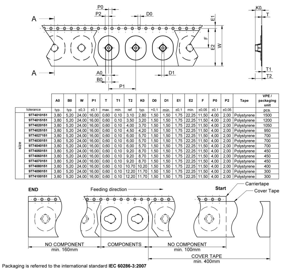
1 A Dimensions: [mm] B Recommended land pattern: [mm] D Properties: Properties Surface Material Thread Tightening torque Solder Cream Thickness Packaging Value Tin plated 11SMnPb30 M Nm 150 µm Reel C Stencil suggestion: E General information: In tape & reel packaging a kapton-film is fixed on the top of the spacer for automatic assembly. During the programming of the Pick and Place machine and the AOI, please consider the flap of the kapton-film. Technical Tolerances according to DIN ISO 2768m In tape & reel packaging a kapton-film is fixed on the top of the spacer to realize automatic assembly
2
3 H Soldering Specifications: H1: Classification Reflow Profile for SMT components: H2: Classification Reflow Profiles Profile Feature Preheat - Temperature Min (T smin ) - Temperature Max (T smax ) - Time (t s ) from (T smin to T smax ) Ramp-up rate (T L to T P ) Liquidous temperature (T L ) Time (t L ) maintained above T L Peak package body temperature (T p ) Time within 5 C of actual peak temperature (t p ) Ramp-down rate (T P to T L ) Time 25 C to peak temperature Pb-Free Assembly 150 C 200 C seconds 3 C/ second max. 217 C seconds See Table H seconds 6 C/ second max. 8 minutes max. refer to IPC/JEDEC J-STD-020D H3: Package Classification Reflow Temperature Package Thickness PB-Free Assembly < 1.6 mm PB-Free Assembly mm PB-Free Assembly 2.5 mm refer to IPC/JEDEC J-STD-020D Volume mm³ < C Volume mm³ C 245 C Volume mm³ > C 245 C
4 I Cautions and Warnings: The following conditions apply to all goods within the product series of WA-SMSI of : General: All recommendations according to the general technical specifications of the data-sheet have to be complied with. The responsibility for the applicability of customer specific products and use in a particular customer design is always within the authority of the customer. All technical specifications for standard products do also apply for customer specific products. Product Specific: Follow all instructions in the datasheet, especially: The solder profile has to be complied with according to the technical reflow soldering specification, otherwise no warranty will be sustained. Surface discoloration due to reflow processing is permitted. Wave soldering is not applicable. Reflow soldering is recommended. All products shall be used before the end of the period of 12 months based on the product date-code, if not a 100% solderability can t be ensured. The maximum permissible torques must be complied with to prevent mechanical destruction of the elements and PCB.
5 J Important Notes: The following conditions apply to all goods within the product range of : 1. General Customer Responsibility Some goods within the product range of contain statements regarding general suitability for certain application areas. These statements about suitability are based on our knowledge and experience of typical requirements concerning the areas, serve as general guidance and cannot be estimated as binding statements about the suitability for a customer application. The responsibility for the applicability and use in a particular customer design is always solely within the authority of the customer. Due to this fact it is up to the customer to evaluate, where appropriate to investigate and decide whether the device with the specific product characteristics described in the product specification is valid and suitable for the respective customer application or not. 2. Customer Responsibility related to Specific, in particular Safety-Relevant Applications It has to be clearly pointed out that the possibility of a malfunction of electronic components or failure before the end of the usual lifetime cannot be completely eliminated in the current state of the art, even if the products are operated within the range of the specifications. In certain customer applications requiring a very high level of safety and especially in customer applications in which the malfunction or failure of an electronic component could endanger human life or health it must be ensured by most advanced technological aid of suitable design of the customer application that no injury or damage is caused to third parties in the event of malfunction or failure of an electronic component. Therefore, customer is cautioned to verify that data sheets are current before placing orders. The current data sheets can be downloaded at. 3. Best Care and Attention Any product-specific notes, cautions and warnings must be strictly observed. Any disregard will result in the loss of warranty. 4. Customer Support for Product Specifications Some products within the product range may contain substances which are subject to restrictions in certain jurisdictions in order to serve specific technical requirements. Necessary information is available on request. In this case the field sales engineer or the internal sales person in charge should be contacted who will be happy to support in this matter. 6. Product Life Cycle Due to technical progress and economical evaluation we also reserve the right to discontinue production and delivery of products. As a standard reporting procedure of the Product Termination Notification (PTN) according to the JEDEC-Standard we will inform at an early stage about inevitable product discontinuance. According to this we cannot guarantee that all products within our product range will always be available. Therefore it needs to be verified with the field sales engineer or the internal sales person in charge about the current product availability expectancy before or when the product for application design-in disposal is considered. The approach named above does not apply in the case of individual agreements deviating from the foregoing for customer-specific products. 7. Property Rights All the rights for contractual products produced by on the basis of ideas, development contracts as well as models or templates that are subject to copyright, patent or commercial protection supplied to the customer will remain with Würth Elektronik eisos GmbH & Co. KG. does not warrant or represent that any license, either expressed or implied, is granted under any patent right, copyright, mask work right, or other intellectual property right relating to any combination, application, or process in which Würth Elektronik eisos GmbH & Co. KG components or services are used. 8. General Terms and Conditions Unless otherwise agreed in individual contracts, all orders are subject to the current version of the General Terms and Conditions of Würth Elektronik eisos Group, last version available at. 5. Product R&D Due to constant product improvement product specifications may change from time to time. As a standard reporting procedure of the Product Change Notification (PCN) according to the JEDEC-Standard inform about minor and major changes. In case of further queries regarding the PCN, the field sales engineer or the internal sales person in charge should be contacted. The basic responsibility of the customer as per Section 1 and 2 remains unaffected.
6 Mouser Electronics Authorized Distributor Click to View Pricing, Inventory, Delivery & Lifecycle Information: Wurth Electronics:
B Recommended land pattern: [mm] C Stencil suggestion: SSt SSt CHECKED DATE
![B Recommended land pattern: [mm] C Stencil suggestion: SSt SSt CHECKED DATE](/thumbs/92/108972358.jpg "B Recommended land pattern: [mm] C Stencil suggestion: SSt SSt CHECKED DATE") A Dimensions: [mm] B Recommended land pattern: [mm] C Stencil suggestion: D Properties: Properties Surface Material Thread Tightening torque Solder Cream Thickness Rated current Packaging Value Tin CuZn39Pb3
A Dimensions: [mm] B Recommended land pattern: [mm] C Stencil suggestion: D Properties: Properties Surface Material Thread Tightening torque Solder Cream Thickness Rated current Packaging Value Tin CuZn39Pb3
Recommended Land Pattern: [mm] Stencil Suggestion:
![Recommended Land Pattern: [mm] Stencil Suggestion:](/thumbs/77/75627151.jpg "Recommended Land Pattern: [mm] Stencil Suggestion:") Dimensions: [mm] Recommended Land Pattern: [mm] Properties: Properties Value Unit Thread M3 Inner Diameter Ø ID 4.2 mm O 6,0 G u 0,1 1,0 O 4,2 sectional drawing - M 3,0 Suggested Solder pad Non plated
Dimensions: [mm] Recommended Land Pattern: [mm] Properties: Properties Value Unit Thread M3 Inner Diameter Ø ID 4.2 mm O 6,0 G u 0,1 1,0 O 4,2 sectional drawing - M 3,0 Suggested Solder pad Non plated
Recommended Land Pattern: [mm] Stencil Suggestion:
![Recommended Land Pattern: [mm] Stencil Suggestion:](/thumbs/90/103462493.jpg "Recommended Land Pattern: [mm] Stencil Suggestion:") Dimensions: [mm] Recommended Land Pattern: [mm] Properties: Properties Value Unit Thread M3 Inner Diameter Ø ID 4.2 mm O 6,0 G u 0,1 1,0 O 4,2 sectional drawing - M 3,0 Suggested Solder pad Non plated
Dimensions: [mm] Recommended Land Pattern: [mm] Properties: Properties Value Unit Thread M3 Inner Diameter Ø ID 4.2 mm O 6,0 G u 0,1 1,0 O 4,2 sectional drawing - M 3,0 Suggested Solder pad Non plated
WE-UKW EMI Suppression 6-Hole Ferrite Bead
 A Dimensions: [mm] D Electrical Properties: Properties Test conditions Value Unit Tol. Impedance @ 25 MHz 25 MHz Z 920 Ω ±25% Impedance @ 100 MHz 100 MHz Z 961 Ω ±25% Rated current ΔT = 40K I R 3.0 A max.
WE-UKW EMI Suppression 6-Hole Ferrite Bead
 A Dimensions: [mm] D Electrical Properties: Properties Test conditions Value Unit Tol. Impedance @ 25 MHz 25 MHz Z 702 Ω ±25% Impedance @ 100 MHz 100 MHz Z 773 Ω ±25% Rated current ΔT = 40K I R 3.0 A max.
WE-UKW EMI Suppression 6-Hole Ferrite Bead
 A Dimensions: [mm] D Electrical Properties: Properties Test conditions Value Unit Tol. Impedance @ 25 MHz 25 MHz Z 320 Ω ±25% Impedance @ 100 MHz 100 MHz Z 512 Ω ±25% Rated current ΔT = 40K I R 3.0 A max.
WE-UKW EMI Suppression 6-Hole Ferrite Bead
 A Dimensions: [mm] D Electrical Properties: Properties Test conditions Value Unit Tol. Impedance @ 25 MHz 25 MHz Z 670 Ω ±25% Impedance @ 100 MHz 100 MHz Z 976 Ω ±25% Rated current ΔT = 40K I R 3.0 A max.
Recommended Land Pattern: [mm] Stencil Suggestion:
![Recommended Land Pattern: [mm] Stencil Suggestion:](/thumbs/88/114837681.jpg "Recommended Land Pattern: [mm] Stencil Suggestion:") Dimensions: [mm] Recommended Land Pattern: [mm] Properties: 5,54 O 0,84 55 detail 0,2 suggested solder pad O 0,97 +0,2-0,0 non plated 3,33 Properties Value Unit Material Surface rass Solder Cream Thickness
Dimensions: [mm] Recommended Land Pattern: [mm] Properties: 5,54 O 0,84 55 detail 0,2 suggested solder pad O 0,97 +0,2-0,0 non plated 3,33 Properties Value Unit Material Surface rass Solder Cream Thickness
WE-UKW EMI Suppression 6-Hole Ferrite Bead
 A Dimensions: [mm] D Electrical Properties: Properties Test conditions Value Unit Tol. Impedance @ 25 MHz 25 MHz Z 920 Ω ±25% Impedance @ 100 MHz 100 MHz Z 961 Ω ±25% Rated current ΔT = 40K I R 3.0 A max.
WE-UKW EMI Suppression 6-Hole Ferrite Bead
 A Dimensions: [mm] D Electrical Properties: Properties Test conditions Value Unit Tol. Impedance @ 25 MHz 25 MHz Z 720 Ω ±25% Impedance @ 100 MHz 100 MHz Z 1240 Ω ±25% Rated current ΔT = 40K I R 3.0 A
WE-CBF SMD EMI Suppression Ferrite Bead
 A Dimensions: [mm] B Recommended land pattern: [mm] D Electrical Properties: Properties Test conditions Value Unit Tol. Impedance @ 100 MHz 100 MHz Z 1000 Ω ±25% Maximum impedance 120 MHz Z 1100 Ω typ.
WE-CBF SMD EMI Suppression Ferrite Bead
 A Dimensions: [mm] B Recommended land pattern: [mm] D Electrical Properties: Properties Test conditions Value Unit Tol. Impedance @ 100 MHz 100 MHz Z 470 Ω ±25% Maximum impedance 230 MHz Z 600 Ω typ. Rated
WE-CBF SMD EMI Suppression Ferrite Bead
 A Dimensions: [mm] B Recommended land pattern: [mm] D Electrical Properties: Properties Test conditions Value Unit Tol. Impedance @ 100 MHz 100 MHz Z 600 Ω ±25% Maximum impedance 250 MHz Z 900 Ω typ. Rated
WE-CBF SMD EMI Suppression Ferrite Bead
 A Dimensions: [mm] B Recommended land pattern: [mm] D Electrical Properties: Properties Test conditions Value Unit Tol. Impedance @ 100 MHz 100 MHz Z 1000 Ω ±25% Maximum impedance 200 MHz Z 1200 Ω typ.
WE-SLM SMD Common Mode Line Filter
 A Dimensions: [mm] B Recommended land pattern: [mm] D Electrical Properties: Properties Test conditions Value Unit Tol. Inductance 100 khz/ 100 mv L 2x 470 µh +50/-30% Impedance 100 MHz Z max 2200 Ω typ.
WE-CBF HF SMD EMI Suppression Ferrite Bead (High Frequency)
") A Dimensions: [mm] B Recommended land pattern: [mm] D Electrical Properties: Properties Test conditions Value Unit Tol. Impedance @ 100 MHz 100 MHz Z 600 ±25% Impedance @ 1 GHz 1 GHz Z 1100 min. Maximum
A Dimensions: [mm] B Recommended land pattern: [mm] D Electrical Properties: Properties Test conditions Value Unit Tol. Impedance @ 100 MHz 100 MHz Z 600 ±25% Impedance @ 1 GHz 1 GHz Z 1100 min. Maximum
WE-CBF HF SMD EMI Suppression Ferrite Bead (High Frequency)
") A Dimensions: [mm] B Recommended land pattern: [mm] D Electrical Properties: Properties Test conditions Value Unit Tol. Impedance @ 100 MHz 100 MHz Z 600 ±25% Impedance @ 1 GHz 1 GHz Z 450 min. Maximum
A Dimensions: [mm] B Recommended land pattern: [mm] D Electrical Properties: Properties Test conditions Value Unit Tol. Impedance @ 100 MHz 100 MHz Z 600 ±25% Impedance @ 1 GHz 1 GHz Z 450 min. Maximum
WE-CBF SMD EMI Suppression Ferrite Bead
 A Dimensions: [mm] B Recommended land pattern: [mm] D Electrical Properties: Properties Test conditions Value Unit Tol. Impedance @ 100 MHz 100 MHz Z 600 Ω ±25% Maximum impedance 150 MHz Z 700 Ω typ. Rated
WE-CBF SMD EMI Suppression Ferrite Bead
 A Dimensions: [mm] B Recommended land pattern: [mm] D Electrical Properties: Properties Test conditions Value Unit Tol. Impedance @ 100 MHz 100 MHz Z 30 Ω ±25% Maximum impedance 1000 MHz Z 40 Ω typ. Rated
WE-CBF SMD EMI Suppression Ferrite Bead
 A Dimensions: [mm] B Recommended land pattern: [mm] D Electrical Properties: Properties Test conditions Value Unit Tol. Impedance @ 100 MHz 100 MHz Z 1000 Ω ±25% Maximum impedance 90 MHz Z 1100 Ω typ.
WE-CBF SMD EMI Suppression Ferrite Bead
 A Dimensions: [mm] B Recommended land pattern: [mm] D Electrical Properties: Properties Test conditions Value Unit Tol. Impedance @ 100 MHz 100 MHz Z 50 Ω ±25% Maximum impedance 1000 MHz Z 82 Ω typ. Rated
WE-CNSW SMD Common Mode Line Filter
 A Dimensions: [mm] B Recommended land pattern: [mm] D Electrical Properties: Properties Test conditions Value Unit Tol. Impedance 100 MHz Z 90 Ω ±25% Rated current T = 40 K I R 370 ma max. DC Resistance
WE-CBF HF SMD EMI Suppression Ferrite Bead (High Frequency)
") A Dimensions: [mm] B Recommended land pattern: [mm] D Electrical Properties: Properties Test conditions Value Unit Tol. Impedance @ 100 MHz 100 MHz Z 1000 ±25% Impedance @ 1 GHz 1 GHz Z 1100 min. Maximum
A Dimensions: [mm] B Recommended land pattern: [mm] D Electrical Properties: Properties Test conditions Value Unit Tol. Impedance @ 100 MHz 100 MHz Z 1000 ±25% Impedance @ 1 GHz 1 GHz Z 1100 min. Maximum
WE-UCF SMD Common Mode Line Filter
 A Dimensions: [mm] B Recommended land pattern: [mm] D Electrical Properties: Properties Test conditions Value Unit Tol. Inductance 10 khz/ 50 mv L 2x 0.013 mh ±30% Rated current T = 40 K I R 10.0 A max.
WE-UCF SMD Common Mode Line Filter
 A Dimensions: [mm] B Recommended land pattern: [mm] D Electrical Properties: Properties Test conditions Value Unit Tol. Inductance 10 khz/ 50 mv L 2x 4.7 mh ±30% Rated current T = 40 K I R 0.75 A max.
WE-UCF SMD Common Mode Line Filter
 A Dimensions: [mm] B Recommended land pattern: [mm] D Electrical Properties: Properties Test conditions Value Unit Tol. Inductance 10 khz/ 50 mv L 2x 0.32 mh ±30% Rated current T = 40 K I R 3.25 A max.
WE-CBA SMD EMI Suppression Ferrite Bead
 A Dimensions: [mm] B Recommended land pattern: [mm] D Properties: Properties Test conditions Value Unit Tol. Impedance 100 MHz Z 1100 Ω ±25% Maximum Impedance 70 MHz Z 1400 Ω typ. Rated Current ΔT = 40K
WE-CBA SMD EMI Suppression Ferrite Bead
 A Dimensions: [mm] B Recommended land pattern: [mm] D Properties: Properties Test conditions Value Unit Tol. Impedance 100 MHz Z 600 Ω ±25% Maximum Impedance 190 MHz Z 660 Ω typ. Rated Current ΔT = 40K
WE-LQS SMD Power Inductor
 A Dimensions: [mm] B Recommended land pattern: [mm] D Electrical Properties: Properties Test conditions Value Unit Tol. Inductance 100 khz/ 1 V L 2.2 µh ±30% Rated current T = 40 K I R 4.60 A max. Saturation
WE-CNSW SMD Common Mode Line Filter
 A Dimensions: [mm] B Recommended land pattern: [mm] D Electrical Properties: Properties Test conditions Value Unit Tol. Inductance 100 khz/ 100 mv L 100 µh +50%/-30% Impedance 10 MHz Z 8000 Ω typ. Rated
WE-HCI SMD Flat Wire High Current Inductor
 A Dimensions: [mm] B Recommended land pattern: [mm] D Electrical Properties: Properties Test conditions Value Unit Tol. Inductance 100 khz/ 10 ma L 22 µh ±20% Rated inductance 100 khz/ 10 ma/ 11.0 A L
WE-CNSW HF SMD Common Mode Line Filter (High Frequency)
") A Dimensions: [mm] B Recommended land pattern: [mm] D Electrical Properties: Properties Test conditions Value Unit Tol. Impedance 100 MHz Z 90 Ω ±25% Rated current T = 20 K I R 500 ma max. DC Resistance
A Dimensions: [mm] B Recommended land pattern: [mm] D Electrical Properties: Properties Test conditions Value Unit Tol. Impedance 100 MHz Z 90 Ω ±25% Rated current T = 20 K I R 500 ma max. DC Resistance
WE-CNSW SMD Common Mode Line Filter
 A Dimensions: [mm] B Recommended land pattern: [mm] D Electrical Properties: Properties Test conditions Value Unit Tol. Inductance 100 khz/ 100 mv L 1.3 µh typ. Impedance 100 MHz Z 800 Ω ±25% Rated current
WE-CNSW HF SMD Common Mode Line Filter (High Frequency)
") A Dimensions: [mm] B Recommended land pattern: [mm] D Electrical Properties: Properties Test conditions Value Unit Tol. Impedance 100 MHz Z 90 Ω ±25% Rated current T = 20 K I R 500 ma max. DC Resistance
A Dimensions: [mm] B Recommended land pattern: [mm] D Electrical Properties: Properties Test conditions Value Unit Tol. Impedance 100 MHz Z 90 Ω ±25% Rated current T = 20 K I R 500 ma max. DC Resistance
WE-MPSB EMI Multilayer Power Suppression Bead
 A Dimensions: [mm] B Land Pattern: [mm] D Electrical Properties: Properties Test conditions Value Unit Tol. Impedance @ 100 MHz 100 MHz Z 56 Ω ±25% Maximum Impedance 1000 MHz Z 90 Ω typ. Rated Current
WE-MPSB EMI Multilayer Power Suppression Bead
 A Dimensions: [mm] B Land Pattern: [mm] D Electrical Properties: Properties Test conditions Value Unit Tol. Impedance @ 100 MHz 100 MHz Z 100 Ω ±25% Maximum Impedance 1200 MHz Z 160 Ω typ. Rated Current
WE-SL2 SMD Common Mode Line Filter
 A Dimensions: [mm] B Recommended land pattern: [mm] D Electrical Properties: Properties Test conditions Value Unit Tol. Inductance 100 khz/ 5 mv L 2x 1000 µh ±50% Impedance Z max 6000 Ω typ. Rated current
WE-SL2 SMD Common Mode Line Filter
 A Dimensions: [mm] B Recommended land pattern: [mm] D Electrical Properties: Properties Test conditions Value Unit Tol. Inductance 100 khz/ 5 mv L 2x 500 µh ±50% Impedance Z max 3300 Ω typ. Rated current
Recommended Land Pattern: [mm]
![Recommended Land Pattern: [mm]](/thumbs/72/67185272.jpg "Recommended Land Pattern: [mm]") Dimensions: [mm] Recommended Land Pattern: [mm] Properties: NEG. CONTCT (PD) Material Surface Phosphor Bronze Nickel O 2,35 5,1 10,45 Battery Type 2016,2020,2025,2032 25,9 30,5 21,1 sectional drawing -
Dimensions: [mm] Recommended Land Pattern: [mm] Properties: NEG. CONTCT (PD) Material Surface Phosphor Bronze Nickel O 2,35 5,1 10,45 Battery Type 2016,2020,2025,2032 25,9 30,5 21,1 sectional drawing -
WE-CFWI Coupled Flatwire Inductor
 Dimensions: [mm] B Recommended land pattern: [mm] D Electrical Properties: Properties Test conditions Value Unit Tol. Inductance 1 100 khz/ 1 m L 1 4.40 µh ±20% Inductance 2 100 khz/ 1 m L 2 4.40 µh ±20%
WE-CFWI Coupled Flatwire Inductor
 Dimensions: [mm] B Recommended land pattern: [mm] D Electrical Properties: Properties Test conditions Value Unit Tol. Inductance 1 100 khz/ 1 m L 1 2.20 µh ±20% Inductance 2 100 khz/ 1 m L 2 2.20 µh ±20%
Dimensions: [mm] Electrical Properties: Schematic: General Information: WE-UKW EMI Suppression 6-Hole Ferrite Bead
![Dimensions: [mm] Electrical Properties: Schematic: General Information: WE-UKW EMI Suppression 6-Hole Ferrite Bead](/thumbs/81/82619494.jpg "Dimensions: [mm] Electrical Properties: Schematic: General Information: WE-UKW EMI Suppression 6-Hole Ferrite Bead") Dimensions: [mm] Electrical Properties: Properties Test conditions Value Unit Tol. Impedance @ 25 MHz 25 MHz 670 Ω ±25% Impedance @ 100 MHz 100 MHz Z 976 Ω ±25% Rated Current ΔT = 40 K I R 3 A max. Curie
Dimensions: [mm] Electrical Properties: Properties Test conditions Value Unit Tol. Impedance @ 25 MHz 25 MHz 670 Ω ±25% Impedance @ 100 MHz 100 MHz Z 976 Ω ±25% Rated Current ΔT = 40 K I R 3 A max. Curie
WE-PD2A SMD Power Inductor
 A Dimensions: [mm] B Recommended land pattern: [mm] D Electrical Properties: Properties Test conditions Value Unit Tol. Inductance 10 KHz/ 100 mv L 47 µh ±10% Rated Current T = 40 K I R 0.68 A max. Saturation
Recommended Land Pattern: [mm] Stencil Suggestion:
![Recommended Land Pattern: [mm] Stencil Suggestion:](/thumbs/90/102451029.jpg "Recommended Land Pattern: [mm] Stencil Suggestion:") Dimensions: [mm] Recommended Land Pattern: [mm] Properties: Properties Value Unit ±0,1 Bevelled edge 0,5 ±0,1 around 5:1 detail B 3,0 ±0,2 O3,2 Solder Pad non plated through-hole Material Brass Surface
Dimensions: [mm] Recommended Land Pattern: [mm] Properties: Properties Value Unit ±0,1 Bevelled edge 0,5 ±0,1 around 5:1 detail B 3,0 ±0,2 O3,2 Solder Pad non plated through-hole Material Brass Surface
WE-SPC SMD Shielded Power Inductor
 A Dimensions: [mm] B Land Pattern: [mm] D Electrical Properties: Properties Test conditions Value Unit Tol. Inductance 100 khz/ 1 ma L 0.68 µh ±30% Rated Current T = 40 K I R 3.40 A max. Saturation Current
Recommended Land Pattern: [mm]
![Recommended Land Pattern: [mm]](/thumbs/92/110917620.jpg "Recommended Land Pattern: [mm]") Dimensions: [mm] Recommended Land Pattern: [mm] Electrical Properties: Properties Test conditions Value Unit Tol. Inductance 0.796 MHz L 100 µh ±10% 3,2 ±0,4 2,9 ±0,2 2,5 ±0,2 1 ±0,2 0,6 +0,3-0,0 2,2 ±0,2
Dimensions: [mm] Recommended Land Pattern: [mm] Electrical Properties: Properties Test conditions Value Unit Tol. Inductance 0.796 MHz L 100 µh ±10% 3,2 ±0,4 2,9 ±0,2 2,5 ±0,2 1 ±0,2 0,6 +0,3-0,0 2,2 ±0,2
Recommended Land Pattern: [mm]
![Recommended Land Pattern: [mm]](/thumbs/77/75871344.jpg "Recommended Land Pattern: [mm]") Dimensions: [mm] 0,3 ± 0,1 Recommended Land Pattern: [mm] 0,762 Electrical Properties: Properties Test conditions Value Unit Tol. Inductance 200 MHz L 56 nh ±5% Q-Factor 200 MHz Q min. 32 min. DC Resistance
Dimensions: [mm] 0,3 ± 0,1 Recommended Land Pattern: [mm] 0,762 Electrical Properties: Properties Test conditions Value Unit Tol. Inductance 200 MHz L 56 nh ±5% Q-Factor 200 MHz Q min. 32 min. DC Resistance
Recommended Land Pattern: [mm]
![Recommended Land Pattern: [mm]](/thumbs/94/118765902.jpg "Recommended Land Pattern: [mm]") Dimensions: [mm] 0,3 ± 0,1 Recommended Land Pattern: [mm] 0,762 Electrical Properties: Properties Test conditions Value Unit Tol. Inductance 250 MHz L 11 nh ±5% Q-Factor 250 MHz Q min. 30 min. DC Resistance
Dimensions: [mm] 0,3 ± 0,1 Recommended Land Pattern: [mm] 0,762 Electrical Properties: Properties Test conditions Value Unit Tol. Inductance 250 MHz L 11 nh ±5% Q-Factor 250 MHz Q min. 30 min. DC Resistance
Recommended Land Pattern: [mm]
![Recommended Land Pattern: [mm]](/thumbs/94/118765807.jpg "Recommended Land Pattern: [mm]") Dimensions: [mm] Recommended Land Pattern: [mm] Electrical Properties: Properties Test conditions Value Unit Tol. 7,9 Inductance 1 MHz L 146 nh ±20% Q-Factor 100 MHz Q 163 typ. 8,55 u 1,0 DC Resistance
Dimensions: [mm] Recommended Land Pattern: [mm] Electrical Properties: Properties Test conditions Value Unit Tol. 7,9 Inductance 1 MHz L 146 nh ±20% Q-Factor 100 MHz Q 163 typ. 8,55 u 1,0 DC Resistance
Recommended Land Pattern: [mm]
![Recommended Land Pattern: [mm]](/thumbs/92/108685678.jpg "Recommended Land Pattern: [mm]") Dimensions: [mm] Recommended Land Pattern: [mm] Electrical Properties: Properties Test conditions Value Unit Tol. Inductance L 1.06 MHz 22 µh ±10% Rated Current I R ΔT = 40 K 650 ma max. DC Resistance
Dimensions: [mm] Recommended Land Pattern: [mm] Electrical Properties: Properties Test conditions Value Unit Tol. Inductance L 1.06 MHz 22 µh ±10% Rated Current I R ΔT = 40 K 650 ma max. DC Resistance
Recommended Land Pattern: [mm]
![Recommended Land Pattern: [mm]](/thumbs/72/66460513.jpg "Recommended Land Pattern: [mm]") Dimensions: [mm] Recommended Land Pattern: [mm] Properties: 4,5 Material Recommended Working Height Copper Beryllium (CuBe) gold-plated(au) 1-1.2 mm 1 ref. 1 ref. 1,6 ref. 2,8 ±0,2 3,2 ±0,2 0,5 ref. 0,08
Dimensions: [mm] Recommended Land Pattern: [mm] Properties: 4,5 Material Recommended Working Height Copper Beryllium (CuBe) gold-plated(au) 1-1.2 mm 1 ref. 1 ref. 1,6 ref. 2,8 ±0,2 3,2 ±0,2 0,5 ref. 0,08
Recommended Land Pattern: [mm]
![Recommended Land Pattern: [mm]](/thumbs/77/75335947.jpg "Recommended Land Pattern: [mm]") Dimensions: [mm] Recommended Land Pattern: [mm] O 0,7 Electrical Properties: Properties Test conditions Value Unit Tol. Impedance @ 25 MHz 25 MHz Z 212 Ω ±25% Impedance @ 100 MHz 100 MHz Z 264 Ω ±25% Curie
Dimensions: [mm] Recommended Land Pattern: [mm] O 0,7 Electrical Properties: Properties Test conditions Value Unit Tol. Impedance @ 25 MHz 25 MHz Z 212 Ω ±25% Impedance @ 100 MHz 100 MHz Z 264 Ω ±25% Curie
Recommended Land Pattern: [mm] Stencil Suggestion:
![Recommended Land Pattern: [mm] Stencil Suggestion:](/thumbs/82/86769336.jpg "Recommended Land Pattern: [mm] Stencil Suggestion:") Dimensions: [mm] Recommended Land Pattern: [mm] Properties: 6:1 detail B O3,2 Solder Pad Properties Value Unit Material Brass Surface Tin ±0,1 ±0,1 Bevelled edge 0,5 ±0,1 around 3,0 ±0,2 O1,85 Via Tightening
Dimensions: [mm] Recommended Land Pattern: [mm] Properties: 6:1 detail B O3,2 Solder Pad Properties Value Unit Material Brass Surface Tin ±0,1 ±0,1 Bevelled edge 0,5 ±0,1 around 3,0 ±0,2 O1,85 Via Tightening
Recommended Land Pattern: [mm]
![Recommended Land Pattern: [mm]](/thumbs/86/93359061.jpg "Recommended Land Pattern: [mm]") Dimensions: [mm] Recommended Land Pattern: [mm] Electrical & Optical Properties: Properties Test conditions Value Unit Tol. Inductance 250 MHz L 6.8 nh ±2% 1,2 0,5 Q-factor 250 MHz Q 28 min. DC Resistance
Dimensions: [mm] Recommended Land Pattern: [mm] Electrical & Optical Properties: Properties Test conditions Value Unit Tol. Inductance 250 MHz L 6.8 nh ±2% 1,2 0,5 Q-factor 250 MHz Q 28 min. DC Resistance
Recommended Land Pattern: [mm]
![Recommended Land Pattern: [mm]](/thumbs/89/97569223.jpg "Recommended Land Pattern: [mm]") Dimensions: [mm] 0,5 ±0,3 Recommended Land Pattern: [mm] 0,7 0,8 0,7 1,45 Electrical Properties Properties Test conditions Value Unit Tol. Inductance 1 MHz/ 5 ma L 2.2 μh ±20% Rated Current ΔT = 20 K I
Dimensions: [mm] 0,5 ±0,3 Recommended Land Pattern: [mm] 0,7 0,8 0,7 1,45 Electrical Properties Properties Test conditions Value Unit Tol. Inductance 1 MHz/ 5 ma L 2.2 μh ±20% Rated Current ΔT = 20 K I
WE-TI Radial Leaded Wire Wound Inductor
 A Dimensions: [mm] B Recommended land pattern: [mm] D Electrical Properties: Properties Test conditions Value Unit Tol. Inductance 100 khz/ 5 ma L 220 µh ±10% Rated current T = 40 K I R 1.20 A max. Saturation
WE-PoEH Power over Ethernet High Power Transformer
 Dimensions: [mm] B Recommended land pattern: [mm] D Electrical Properties: Properties Test conditions alue Unit Tol. Inductance 100 khz/ 100 m L 21 µh ±10% Turns ratio n 1.33:1:1:0.89 ±3% Saturation current
WE-TCI Thinfilm Chip Inductor
 A Dimensions: [mm] B Recommended land pattern: [mm] D Electrical Properties: Properties Test conditions Value Unit Tol. Inductance L 2.7 nh ± 0.1nH Qfactor Q 13 min. Qfactor Q 15.18 typ. DC Resistance
WE-CMBNC Common Mode Power Line Choke Nanocrystalline
 A Dimensions: [mm] B Recommended hole pattern: [mm] D Electrical Properties: Properties Test conditions Value Unit Tol. Inductance 10 khz/ 0.1 ma L 2x 14.0 mh +50%/-30% Rated current @ 70 C I R 8.0 A DC
WE-LLCR Resonant Converter
 A Dimensions: [mm] B Recommended land pattern: [mm] D Electrical Properties: Properties Test conditions Value Unit Tol. Inductance 100 khz/ 100 mv L 400 µh ±10% Turns ratio n 27 : 6 : 6 : 2 ±3% Saturation
Recommended Land Pattern: [mm]
![Recommended Land Pattern: [mm]](/thumbs/73/69201515.jpg "Recommended Land Pattern: [mm]") Dimensions: [mm] Recommended Land Pattern: [mm] Electrical Properties: Properties Test conditions Value Unit Tol. Inductance 100 khz/ 10 ma L 68 µh ±30% Rated Current ΔT = 30 K I R 0.32 A max. Saturation
Dimensions: [mm] Recommended Land Pattern: [mm] Electrical Properties: Properties Test conditions Value Unit Tol. Inductance 100 khz/ 10 ma L 68 µh ±30% Rated Current ΔT = 30 K I R 0.32 A max. Saturation
Product Marking: Schematic: General Properties: WE-PD SMT Shielded Power Inductor SIZE REVISION STATUS DATE (YYYY-MM-DD) BUSINESS UNIT PAGE
 BUSINESS UNIT PAGE") Product Marking: Start of Winding Schematic: General Properties: It is recommended that the temperature of the component does not exceed +125 C under worst case conditions Storage Conditions (in original
Product Marking: Start of Winding Schematic: General Properties: It is recommended that the temperature of the component does not exceed +125 C under worst case conditions Storage Conditions (in original
Dimensions: [mm] Recommended Land Pattern: [mm] 3,5 pl 3,5 1,0 0,6. Pattern Properties: Article Properties:
![Dimensions: [mm] Recommended Land Pattern: [mm] 3,5 pl 3,5 1,0 0,6. Pattern Properties: Article Properties:](/thumbs/74/71304573.jpg "Dimensions: [mm] Recommended Land Pattern: [mm] 3,5 pl 3,5 1,0 0,6. Pattern Properties: Article Properties:") Dimensions: [mm] Recommended Land Pattern: [mm] 3,5 pl 3,5 1,0 0,6 1 End 2,2 1 End 2,6 1,0 ±0,05 L ±0,15 L2 ±0,1 Pl ±0,1 h 0,13 0,35 ±0,05 3,00 ±0,15 1,7 General tolerance ±0,05 Pl Pl 1,7 1,7 ±0,25 7,1
Dimensions: [mm] Recommended Land Pattern: [mm] 3,5 pl 3,5 1,0 0,6 1 End 2,2 1 End 2,6 1,0 ±0,05 L ±0,15 L2 ±0,1 Pl ±0,1 h 0,13 0,35 ±0,05 3,00 ±0,15 1,7 General tolerance ±0,05 Pl Pl 1,7 1,7 ±0,25 7,1
WE-PD2 HV SMD Power Inductor (High Voltage)
") A Dimensions: [mm] B Recommended land pattern: [mm] D Electrical Properties: Properties Test conditions Value Unit Tol. Inductance 100 khz/ 250 mv L 2200 µh ±10% Rated current T = 40 K I R 0.15 A max.
A Dimensions: [mm] B Recommended land pattern: [mm] D Electrical Properties: Properties Test conditions Value Unit Tol. Inductance 100 khz/ 250 mv L 2200 µh ±10% Rated current T = 40 K I R 0.15 A max.
Electrical Properties: Dimensions: [mm] Schematic: General Properties: WE-FI Leaded Toroidal Line Choke ORDER CODE
![Electrical Properties: Dimensions: [mm] Schematic: General Properties: WE-FI Leaded Toroidal Line Choke ORDER CODE](/thumbs/71/65614107.jpg "Electrical Properties: Dimensions: [mm] Schematic: General Properties: WE-FI Leaded Toroidal Line Choke ORDER CODE") Dimensions: [mm] Electrical Properties: Properties Test conditions Value Unit Tol. Inductance 10 khz/ 5 ma L 220 µh ±20% Rated Current ΔT = 40 K I R 2 A max. DC Resistance R DC 0.16 Ω max. 15,8 max 7,5
Dimensions: [mm] Electrical Properties: Properties Test conditions Value Unit Tol. Inductance 10 khz/ 5 ma L 220 µh ±20% Rated Current ΔT = 40 K I R 2 A max. DC Resistance R DC 0.16 Ω max. 15,8 max 7,5
Recommended Land Pattern: [mm]
![Recommended Land Pattern: [mm]](/thumbs/76/74444087.jpg "Recommended Land Pattern: [mm]") Dimensions: [mm] Recommended Land Pattern: [mm] Electrical Properties: Properties Test conditions Value Unit Tol. 0,9 typ. Inductance 100 khz/ 10 ma L 2.2 µh ±30% Rated Current ΔT = 40 K I R 1.3 A typ.
Dimensions: [mm] Recommended Land Pattern: [mm] Electrical Properties: Properties Test conditions Value Unit Tol. 0,9 typ. Inductance 100 khz/ 10 ma L 2.2 µh ±30% Rated Current ΔT = 40 K I R 1.3 A typ.
Recommended Land Pattern: [mm]
![Recommended Land Pattern: [mm]](/thumbs/86/94587153.jpg "Recommended Land Pattern: [mm]") Dimensions: [mm] Recommended Land Pattern: [mm] Electrical Properties: Properties Test conditions Value Unit Tol. Inductance 100 khz/ 1 ma L 15 µh ±20% Rated Current ΔT = 40 K I R 0.72 A typ. Saturation
Dimensions: [mm] Recommended Land Pattern: [mm] Electrical Properties: Properties Test conditions Value Unit Tol. Inductance 100 khz/ 1 ma L 15 µh ±20% Rated Current ΔT = 40 K I R 0.72 A typ. Saturation
Recommended Land Pattern: [mm]
![Recommended Land Pattern: [mm]](/thumbs/92/108615782.jpg "Recommended Land Pattern: [mm]") Dimensions: [mm] Recommended Land Pattern: [mm] Electrical Properties: Properties Test conditions Value Unit Tol. Inductance 100 khz/ 1 ma L 2.2 µh ±20% Rated Current ΔT = 40 K I R 1.8 A typ. Saturation
Dimensions: [mm] Recommended Land Pattern: [mm] Electrical Properties: Properties Test conditions Value Unit Tol. Inductance 100 khz/ 1 ma L 2.2 µh ±20% Rated Current ΔT = 40 K I R 1.8 A typ. Saturation
Recommended Land Pattern: [mm] Dimensions: [mm] Article Properties: USB 2.0 Type A Horizontal SMT Short Type WR-COM
![Recommended Land Pattern: [mm] Dimensions: [mm] Article Properties: USB 2.0 Type A Horizontal SMT Short Type WR-COM](/thumbs/82/84877373.jpg "Recommended Land Pattern: [mm] Dimensions: [mm] Article Properties: USB 2.0 Type A Horizontal SMT Short Type WR-COM") Dimensions: [mm] Recommended Land Pattern: [mm] 7 ±0,15 0,7 ±0,20 O 1,20 ±0.15 2,45 ±0,15 1,25 ±0,15 2 ±0,50 0,55 ±0,15 2,50 ±0,15 2,00 ±0,15 2,50 ±0,15 13,1 ±0,15 5,72 ±0,15 6,30 ±0,15 2 ±0,50 O 1,5 ±0,15
Dimensions: [mm] Recommended Land Pattern: [mm] 7 ±0,15 0,7 ±0,20 O 1,20 ±0.15 2,45 ±0,15 1,25 ±0,15 2 ±0,50 0,55 ±0,15 2,50 ±0,15 2,00 ±0,15 2,50 ±0,15 13,1 ±0,15 5,72 ±0,15 6,30 ±0,15 2 ±0,50 O 1,5 ±0,15
Dimensions: [mm] Recommended Land Pattern: [mm] Pattern Properties: Article Properties: 0.50mm SMT ZIF Horizontal Top Contact WR-FPC
![Dimensions: [mm] Recommended Land Pattern: [mm] Pattern Properties: Article Properties: 0.50mm SMT ZIF Horizontal Top Contact WR-FPC](/thumbs/91/105083509.jpg "Dimensions: [mm] Recommended Land Pattern: [mm] Pattern Properties: Article Properties: 0.50mm SMT ZIF Horizontal Top Contact WR-FPC") Dimensions: [mm] Recommended Land Pattern: [mm] 0,96 3,28 pl 3,28 0,50 0,30 1 End 1,20 0,2 ±0,05 0,50 ±0,15 1 End 3,00 L ±0,15 L1 ±0,10 Pl ±0,10 4,30 ±0,15 2,10 ±0,15 General tolerance ±0,05 2,70 Pl h
Dimensions: [mm] Recommended Land Pattern: [mm] 0,96 3,28 pl 3,28 0,50 0,30 1 End 1,20 0,2 ±0,05 0,50 ±0,15 1 End 3,00 L ±0,15 L1 ±0,10 Pl ±0,10 4,30 ±0,15 2,10 ±0,15 General tolerance ±0,05 2,70 Pl h
Dimensions: [mm] Recommended Land Pattern: [mm] Pattern Properties: Article Properties: 0.50mm SMT ZIF Horizontal Bottom Contact WR-FPC
![Dimensions: [mm] Recommended Land Pattern: [mm] Pattern Properties: Article Properties: 0.50mm SMT ZIF Horizontal Bottom Contact WR-FPC](/thumbs/92/110714931.jpg "Dimensions: [mm] Recommended Land Pattern: [mm] Pattern Properties: Article Properties: 0.50mm SMT ZIF Horizontal Bottom Contact WR-FPC") Dimensions: [mm] Recommended Land Pattern: [mm] 0,96 pl ±0,15 3,28 0,50 0,30 1,20 1 End 1 End 0,20 ±0,05 0,50 ±0,15 3,00 L ±0,15 2,10 ±0,15 2,70 General tolerance ±0,05 Pl h 0,13 Pl Pl ±0,10 L1 ±0,10 0,80
Dimensions: [mm] Recommended Land Pattern: [mm] 0,96 pl ±0,15 3,28 0,50 0,30 1,20 1 End 1 End 0,20 ±0,05 0,50 ±0,15 3,00 L ±0,15 2,10 ±0,15 2,70 General tolerance ±0,05 Pl h 0,13 Pl Pl ±0,10 L1 ±0,10 0,80
Recommended Land Pattern: [mm]
![Recommended Land Pattern: [mm]](/thumbs/91/105181600.jpg "Recommended Land Pattern: [mm]") Dimensions: [mm] Recommended Land Pattern: [mm] Electrical Properties: Properties Test conditions Value Unit Tol. Frequency Range f 5150-5875 MHz 1,3 Insertion Loss IL 5150-5875 MHz 1.5 db max. VSWR 5150-5875
Dimensions: [mm] Recommended Land Pattern: [mm] Electrical Properties: Properties Test conditions Value Unit Tol. Frequency Range f 5150-5875 MHz 1,3 Insertion Loss IL 5150-5875 MHz 1.5 db max. VSWR 5150-5875