Europe Bill Acceptor EBA xx
|
|
|
- Gloria Gaines
- 6 years ago
- Views:
Transcription
1 Europe Bill Acceptor EBA xx CHAPTER 1 Table of Contents & Model Numbers DWG No Date JAPAN CASHMACHINE CO., LTD. Copyright 1997 Japan Cash Machine Co., Ltd.
2 Contents Contents ➀ Chapter Table of Contents & Product Name ➁Chapter Operation Manual ➂ Chapter Communication Specifications ID-001 (parallel Interface) ID-003 (serial Interface) ➃ Chapter Disassembly & Assembly Procedure ➄ Chapter Wiring Diagram ➅ Chapter Trouble Shooting ➆ Chapter Adjustment Manual Performance Test ➇ Chapter Parts List ➈ Chapter Schematics Layouts TABLE OF CONTENTS & MODEL NUMBERS Japan Cash Machine Co., Ltd. Class EBA-10-PB Chapter 1 Date Dwg No Contents
3 EBA Product Name EBA Product Name Product name consists of two parts, it s [Model] name and it s [Type] name. TABLE OF CONTENTS & MODEL NUMBERS [Model] Name Japan Cash Machine Co., Ltd. Class EBA-10-PB Chapter 1 Date Dwg No Page 1
4 [Type] Name [Type] Name Soft protocol number Kind of option This section provides information about the case of special specifications. The The country names of of a a bill bill to to be be identified are are determined based on on ISO ISO TABLE OF CONTENTS & MODEL NUMBERS ➀ Cassette box type 4: Cassette box which can store 400 bills 6: Cassette box which can store 600 bills (future release) ➁ Faceplate type 0: No faceplate *: The faceplate is provided as decided after discussions ➂ Type of guide block for setting the bill insertion slot width The guide block is selected at the factory on each country basis in accordance with the maximum width of the bills to be sensed. 1: Bills up to 78mm wide (maximum insertion slot width) 2: Bills up to 68mm wide 3: Bills up to 72mm wide ➀ Soft protocol type Two types of protocols are supported by the ROM. 01: ID-001 (parallel interface) 03: ID-003 (serial interface) Japan Cash Machine Co., Ltd. Class EBA-10-PB Chapter 1 Date Dwg No Page 2
5 EBA Product Name EBA product name constitutes two kinds; it is [ MODEL ] name and [ TYPE ] name. EBA SD2 - * * * - * * * [ MODEL ] name [ TYPE ] name [ MODEL ] name EBA SD2 Stack type Series on the product from stack type The product form Japan Cash Machine Co., Ltd. Class EBA-10-SD2 Chapter 1 Date Dwg No Page 2.
6 [TYPE] Name!!!"!"!"!!!!!!!!!"!"!"!!!!!!!!"!"!"!!!!!!!!!!!!!!!!!!!!!!!!!!!!!!!#!$!%!!!!!!!!!!!!& soft protocol number kind of option use a nation cord of ISO 3166 that show the! nation of discriminated money. "Cassette box type 4: Cassette box which can store 400 bills 6: Cassette box which can store 600 bills (future release) # Faceplate type 0 : No faceplate ' : The faceplate is provided as decided after discussions. $Type of guide block for setting the bill insertion slot width The guide block i5 selected at the factory on each country basis in accordance with the maximum width of the bills to be sensed. 1: Bills up to 78mm wide (maximum insertion slot width) 2: Bills up to 68mm wide 3: Bills up to 72mm wide %Soft protocol type Two types of protocols are supported by the ROM. 01: ID001 (parallel interface) 02: ID003 (serial interface) Japan Cash Machine Co., Ltd. Class EBA-10-SD2 Chapter 1 Date Dwg No Page 3.
7 Europe Bill Acceptor EBA xx CHAPTER 2 Operation Manual DWG No Date JAPAN CASHMACHINE CO., LTD. Copyright 1997 Japan Cash Machine Co., Ltd.
8 Contents Contents Page 1 Features 1 2 Component Names Precautions Collecting Bills When the Acceptor is Jammed..4 O P E R A T I O N M A N U A L 6 Cleaning Installation Outline of Interface Input/Output circuits Cabling Pin Assignment...10~12 12 DIP Switch Setting.. 13~14 13 Operation Flowchart 15~17 14 General Specifications Outside Dimensions..19 Japan Cash Machine Co., Ltd. Class EBA-10-PB Chapter 2 Date Dwg No Contents
9 1 Features Validator EBA-10-PB provides the following features. Setting for accepting a bill It can be set up independently whether the reception of the bill is possible by using DIP-SW. O P E R A T I O N M A N U A L A bill collection direction can be chosen. Flexible collection corresponding to the conditions is possible in the space and so on because three kinds of bill discharge directions can be chosen as the collection of the bill. Bill theft prevention mechanism A security device is installed to prevent illegal action. Once a bill is fed into the unit, it cannot be pulled out. Japan Cash Machine Co., Ltd. Class EBA-10-PB Chapter 2 Date Dwg No A Page 1
10 2 Component Names O P E R A T I O N M A N U A L Japan Cash Machine Co., Ltd. Class EBA-10-PB Chapter 2 Date Dwg No A Page 2
11 3 Precautions 1.Do not insert a torn, folded, or wet bill. It will get jammed in the unit. 2.Never expose the unit to water. The unit contains several Precision electronic devices which can be damaged if water or any liquid is sprayed or spilled into the unit. 3.Do not install the unit in a dusty environment. Dust will lower the performance of the bill sensor. O P E R A T I O N M A N U A L 4 Collecting Bills It can be collected in the exchange plate in 3 ways. Japan Cash Machine Co., Ltd. Class EBA-10-PB Chapter 2 Date Dwg No A Page 3
12 5 When the Acceptor is Jammed (1) Remove the bill which loosened the knob of the left - right 4 place and which opened the acceptor head part and which it choked it with when a bill is jammed in the inside of the acceptor. O P E R A T I O N M A N U A L (2) Cancel a slide lock on the left right side of the PB unit, and remove the bill which opened the cap of the PB unit and which choked it, with a string and so on. Japan Cash Machine Co., Ltd. Class EBA-10-PB Chapter 2 Date Dwg No A Page 4
13 5 When the Acceptor is Jammed (1) When bills are jammed near the entrance of the stacker box, unlock the box and pull it out to remove the jammed bills. (2) Loosen 2 knobs each from either side to open the acceptor head and remove the jammed bills. Japan Cash Machine Co., Ltd. Class EBA-10-SD2 Chapter 2(4) Date Dwg No Page 4
14 (1) When you cannot remove jammed Bills even after opening the acceptor head, open the cover of bill theft prevention unit to remove the jammed bills and strings. (4) When bills are jammed in the feed route, remove 2 screws at the back and 2 screws each from either side of the stacker storage unit to pull out the feed unit and remove the jammed bills. Japan Cash Machine Co., Ltd. Class EBA-10-SD2 Chapter 2(4) Date Dwg No Page 5
15 6 Cleaning When the acanning unit and its sensor becomes dirty, this could cause paper jams and deterioration of the bill scanning capability. Periodically open the acceptor and bill theft prevention unit and clean the inner parts of these units. O P E R A T I O N M A N U A L Use a soft cloth or cotton swab to clean the inner parts. If you can not remove a stain, wipe it using a cloth or cotton swab moistened with a standard head cleaner sold in the market. Never use organic solvents such as thinners to clean the inside parts. Do no use organic solvent like thinner. Japan Cash Machine Co., Ltd. Class EBA-10-PB Chapter 2 Date Dwg No A Page 5
16 6 Cleaning When the scanning unit and its sensor becomes dirty, this could cause paper jams and deterioration of the bill sensing capability. Periodically open the acceptor and bill theft prevention unit and clean the inner parts of these units. Use a soft cloth or cotton swab to clean the inner parts. If you cannot remove a stain, wipe it using a cloth or cotton swab moistened with a standard head cleaner sold in the market. Never use organic solvents such as thinners to clean the inside parts: Do no use organic solvent like thinner. Japan Cash Machine Co., Ltd. Class EBA-10-SD2 Chapter 2(4) Date Dwg No Page 6
17 7 Installation (1) Installation An installation screw in the bottom 4 place is to be careful not to project inside more than 3mm and install an installation hole securely. O P E R A T I O N M A N U A L (2) Replacing the width guides of the bill insertion slot. To replace the width guides of the bill insertion slot, remove the screws from the back side of these width guides. Japan Cash Machine Co., Ltd. Class EBA-10-PB Chapter 2 Date Dwg No A Page 6
18 7 Installation (1) Installing the unit: There are 4 installation holes each on the rear and bottom cover panels of the unit. (2) Replacing the width guides of the bill insertion slot To replace the width guides of the bill insertion slot, remove the screws from the back side of these width guides. Bank notes to accept Between Width min 65mm ~ 78 mm Length min 125mm ~ 170mm Japan Cash Machine Co., Ltd. Class EBA-10-SD2 Chapter 2(4) Date Dwg No Page 7
19 8 Outline of Interface The following 2 types of interfaces can be provided in Validator EBA-10-PB, depending on the ROM. (1) ID-001 interface ID-001 interface offers parallel interface support for 7 output lines and 3 input lines. The status of the acceptor is output by the ABN, BSY and STKF output signals. The type of currency received is output by the VEND 1 to VEND 3 and VALID output signals. The acceptor operation can be controlled by the ACK, REJ and INH input signals. See the attached Communications Specifications ID-001 for communication specifications. (2) ID-003 interface The ID-003 interface is a 2-way serial interface. You can control the acceptor status and operation of the acceptor and confirm the settings of each function by sending a polling Status Request and commands ( Operation command and Setting command ) from the controller. See the attached Communications Specifications ID-003 for communication specifications. O P E R A T I O N M A N U A L (3) ID-082 interface Japan Cash Machine Co., Ltd. Class EBA-10-PB Chapter 2 Date Dwg No A Page 7
20 9 Input/Output Circuits ID-001 interface circuit O P E R A T I O N M A N U A L ID-003 interface circuit Circuit for output signal to turn ON the display LED Japan Cash Machine Co., Ltd. Class EBA-10-PB Chapter 2 Date Dwg No A Page 8
21 10 Cabling O P E R A T I O N M A N U A L Japan Cash Machine Co., Ltd. Class EBA-10-PB Chapter 2 Date Dwg No A Page 9
22 11 Pin Assignment ID-001 interface CPU BOARD O P E R A T I O N M A N U A L Japan Cash Machine Co., Ltd. Class EBA-10-PB Chapter 2 Date Dwg No A Page 10
23 ID-003 interface CPU BOARD O P E R A T I O N M A N U A L Japan Cash Machine Co., Ltd. Class EBA-10-PB Chapter 2 Date Dwg No A Page 11
24 ID-082 interface CPU BOARD O P E R A T I O N M A N U A L Japan Cash Machine Co., Ltd. Class EBA-10-PB Chapter 2 Date Dwg No A Page 12
25 12 DIP Switch Setting DIP switch setting (ID-001) You can set the type of currency to be received, the escrow mode, and other functions using the DIP switch settings. O P E R A T I O N M A N U A L DIP switch setting (ID-003) The available DIP switch settings are as follows: Japan Cash Machine Co., Ltd. Class EBA-10-PB Chapter 2 Date Dwg No A Page 13
26 DIP switch setting (ID-082) O P E R A T I O N M A N U A L Japan Cash Machine Co., Ltd. Class EBA-10-PB Chapter 2 Date Dwg No A Page 14
27 13 Operation Flowchart ID-001 interface operation flowchart O P E R A T I O N M A N U A L Japan Cash Machine Co., Ltd. Class EBA-10-PB Chapter 2 Date Dwg No A Page 15
28 ID-003 interface operation flowchart O P E R A T I O N M A N U A L Japan Cash Machine Co., Ltd. Class EBA-10-PB Chapter 2 Date Dwg No A Page 16
29 14 General Specifications 1. Type of currency accepted: See relevant specifications. 2. Direction of insertion: See relevant specifications. 3. Receiving rate: 90% or more. Be sure to use the specified guide block for the bill insertion slot. Includes the first time return and second time acceptance. The following bills however, are excluded: (1) Dirty, worn, wet, torn and badly wrinkled bills. (2) Bills with corner or edge folded and overlapped. (3) Bills which have considerably different cutting dimensions and print displacement. 4. Identification time: Approx. 4 seconds (Time interval until the storage confirmation signal is output after bills are inserted and stacked.) 5. Interface: ID-001: Photo coupler isolation input/output ID-082: Photo coupler isolation input/output ID-003: TTL level 6. Escrow: ID-001: 1 sheet escrow (when the DIP switch is set) ID-003: 7. Display: Four LEDs can be lit. (1) LED ON signal output 2 lines during bill reception enabled status. (2) LED ON signal output 2 lines during error detection and trouble status. 8. Power supply: DC 12V (+/- 5%) 9. Power consumption: (1) Standby status: 4VA (2)Operating status: 6VA 10. Operating environment: (1) Operating temperature: 0 to 40 degrees Celsius (2) Storage temperature: -20 to 70 degrees Celsius (3) Humidity: 30% to 85% RH (without condensation) (4) Light disturbance: Do not expose the unit to direct sunlight. (5) Installation: Indoors 11. Outside dimensions: See attached drawing. 12. Weight: Main unit (with cassette box) approx. 1.2kg 13. Installation: Horizontal installation O P E R A T I O N M A N U A L Japan Cash Machine Co., Ltd. Class EBA-10-PB Chapter 2 Date Dwg No A Page 17
30
31 15 Outside Dimensions O P E R A T I O N M A N U A L Japan Cash Machine Co., Ltd. Class EBA-10-PB Chapter 2 Date Dwg No A Page 18
32
33 Europe Bill Acceptor EBA 10 xx CHAPTER 4 Disassembly and Assembly DWG No Date 97-11
34 Contents 1 Disassembling the unit Removing the stacker box Removing the acceptor Removing the feed unit Removing the push mechanism unit Disassembling the Acceptor Disassembling the upper scanning unit Disassembling the lower scanning unit Disassembling the Feed Unit Removing the belt and motor Disassembling the Push Mechanism Detaching the motor and sensor board 12 5 Disassembling the main Unit Detaching the motor, main board and sensor board DISASSEMBLY AND ASSEMBLY PROCEDURES Japan Cash Machine Co., Ltd. Class EBA-10-PB Chapter 4 Date Dwg No Contents
35 1 Disassembly of Unit 1. Disassembly of acceptor and PB unit (1) Remove 3 screws to detach the acceptor from the PB unit. TABLE OF CONTENTS & MODEL NUMBER Japan Cash Machine Co., Ltd. Class EBA-10-PB Chapter 1 Date Dwg No Page 1
36 1. Disassembling the Validator 1. Removing the stacker box. (1) After removing the key, lift and hold the stacker box and then pull it out forward. 2. Removing the acceptor. (1) Remove 4 screws and 2 washers from the bottom of the acceptor. Disconnect the connector to remove the acceptor. Japan Cash Machine Co., Ltd. Class EBA SD2 Chapter 4 Date Dwg No Page 1
37 2. Removing the feed unit. (1) Remove 2 screws to detach the left side cover plate. Next, disconnect the connector inside the unit. (2) Remove 2 screws each from either side and 2 screws from the lower portion of the stacker box storage. Japan Cash Machine Co., Ltd. Class EBA SD2 Chapter 4 Date Dwg No Page 2
38 (3) Pass the connector cable carefully through the hole and pull out the feed unit. 3. Removing the push mechanism unit (1) Remove 2 screws to detach the right side cover plate and disconnect inside the unit. Japan Cash Machine Co., Ltd. Class EBA SD2 Chapter 4 Date Dwg No Page 2
39 (2) Remove 2 screws each from either side to remove the bothom lid plate. (3) Pass the connector cable carefully through the hole and pull out the push mechanism unit. Japan Cash Machine Co., Ltd. Class EBA SD2 Chapter 4 Date Dwg No Page 2
40 2 Disassembly of Acceptor 1. Disassembly of upper scanning unit (1) Remove 2 screws each on either side to remove the top cover. Be sure the screws remain attached to the cover. TABLE OF CONTENTS & MODEL NUMBER (2) Remove the 2 connectors and loosen 2 knobs each on either side until the retaining boss comes out. Then lift the upper scanning unit to detach it. Japan Cash Machine Co., Ltd. Class EBA-10-PB Chapter 1 Date Dwg No Page 2
41 (3) Remove 1 screw on the left side panel. TABLE OF CONTENTS & MODEL NUMBER (4) Remove 3 screws and disconnect the connector to detach the CPU board. Japan Cash Machine Co., Ltd. Class EBA-10-PB Chapter 1 Date Dwg No Page 3
42 (5) Remove 2 screws to detach the mother headboard. TABLE OF CONTENTS & MODEL NUMBER 2. Disassembly of lower scanning unit (1) Remove 1 screw each on either side to remove the front cover. Then remove 1 screw each on either side and 1 screw on the bottom plate to remove the rear cover. Japan Cash Machine Co., Ltd. Class EBA-10-PB Chapter 1 Date Dwg No Page 4
43 (2) Remove 2 knobs and 1 screw each on either side and disconnect the connector. TABLE OF CONTENTS & MODEL NUMBER (3) Pushing the side panels of the housing slightly outward, lift out the assembly inside. Japan Cash Machine Co., Ltd. Class EBA-10-PB Chapter 1 Date Dwg No Page 5
44 (4) Remove 1 screw on top and disconnect the connector to remove the motor assembly. TABLE OF CONTENTS & MODEL NUMBER (5) Remove 2 screws to detach the LED board. Japan Cash Machine Co., Ltd. Class EBA-10-PB Chapter 1 Date Dwg No Page 6
45 (6) Remove 1 screw to remove the motor. TABLE OF CONTENTS & MODEL NUMBER (7) Remove 1 spring, 2 E-rings, and 2 gears to remove the belt. Japan Cash Machine Co., Ltd. Class EBA-10-PB Chapter 1 Date Dwg No Page 7
46 2 Disassembly of PB Unit 1. Removing the Board (1) Remove 2 screws each on either side to remove the bottom plate. TABLE OF CONTENTS & MODEL NUMBER (2) Remove 1 screw to detach the board. Japan Cash Machine Co., Ltd. Class EBA-10-PB Chapter 1 Date Dwg No Page 8
47 2. Removing the motors, sensor boards, and belt (1) Remove 2 screws each on either side to remove both side panels. TABLE OF CONTENTS & MODEL NUMBER (2) Remove the rear guide and pull out the shaft to remove the top cover. Japan Cash Machine Co., Ltd. Class EBA-10-PB Chapter 1 Date Dwg No Page 9
48 (3) Remove 4 screws to remove two motors. TABLE OF CONTENTS & MODEL NUMBER (4) Remove 2 screws to detach the sensor boards. Japan Cash Machine Co., Ltd. Class EBA-10-PB Chapter 1 Date Dwg No Page 10
49 (5) Remove the E-ring and bearing and pull out the shaft from the opposite side to remove the pulley, belt, springs, another shaft, and pin. TABLE OF CONTENTS & MODEL NUMBER Japan Cash Machine Co., Ltd. Class EBA-10-PB Chapter 1 Date Dwg No Page 11
50
51
52
53
54 Europe Bill Acceptor EBA 10 xx CHAPTER 5 Wiring Diagram DWG No Date 97-11
55 Contents 1. General Wiring Diagram EBA-10-SD Acceptor Unit EBA-10-SD Stacker Unit EBA-10-SD TWIRING DIAGRAM Japan Cash Machine Co., Ltd. Class EBA-10-PB Chapter 5 Date Dwg No Contents
56
57
58
59 Europe Bill Acceptor EBA 10 xx CHAPTER 6 Trouble Shooting DWG No Date 97-11
60 Contents Introduction Outline of Troubleshooting Connecting the EBA and V M Bill Identification Operation Test Procedure EBA Trouble Indication and Bill Rejection Trouble Indication Trouble Classification Error Code Sensor Lay out 10 8 Printed circuit board connection diagram...11 TROUBLE SHOOTING Japan Cash Machine Co., Ltd. Class EBA-10-PB Chapter 6 Date Dwg No Contents
61 Introduction Many troubles of the validator are caused by minor reasons. Before replacing any part, be sure to check whether connectors are connected properly and there is no line breakage in a cable harness. If the validator frequently rejects a bill, the magnetic head and conve you r belt may have a lay er of iron particles on them. Clean these areas. Observe the operating conditions of the validator carefully when y ou turn on the power. This is important for the detection of a trouble cause and defective location. Whenever y ou disassemble and repair the validator head, be sure to adjust the sensors. Perform repairs in accordance with Chapter 7, Adjustment Manual Performance Test, and Chapter 4, Disassembly Procedure. TROUBLE SHOOTING Japan Cash Machine Co., Ltd. Class EBA-10-PB Chapter 6 Date Dwg No Page 1


62 1 Outline of Troubleshooting EBA can find a trouble cause by performing the bill identification operation test. The performance test or sensor adjustment is performed according to the identified trouble cause and the necessary repairs and replacement of parts are performed. Investigation of trouble cause VM-450 Trouble Shooting Cause A Cause B Performance Test Analysis of trouble EBA-10/410 (Test mode Execution of bill identification operation test) Adjustment Manual IBM PC Sensor Adjustment MAG test tool MAG BOARD Cable Analysis of trouble TROUBLE SHOOTING 2 Connecting the EBA with VM- 450 or MIB 232 EBA-10/410 VM-450 MIB232 EBA-10/410 Japan Cash Machine Co., Ltd. Class EBA-10-PB Chapter 6 Date Dwg No Page 2


63 3 Bill Identification Operation Test Procedure 3-1 To perform the bill identification operation test, first set the acceptor to the test mode standby status. Set the DIP switches of EBA-10/410 and VM-450 as shown in the figure below. Make sure to turn off VM-450 before changing the DIP switch. 3-2 When you turn on the power of VM-450, the BSY LED lights and _000_00 will appear on the segment display. At this time, the DIP switch next the LED of EBA will light. This is called the test mode standby status. You can perform various operation tests in this status. TROUBLE SHOOTING 3-3 Executing the identification operation tests Set the DIP switch of the acceptor as shown in the figure below. 3-4 When you turn off DIP switch No. 1 of the acceptor, the acceptor can receive a bill and you can confirm the bill receiving rate after the initial operation is completed. VM-450 indicates that the bill is received and the type of currency is indicated by means of the VEND1 to VEND3 LED combinations. VM-450 currency type signal indication Currency type VEND1 VEND2 VEND3 Currency type 1 O - - Currency type 2 - O - Currency type 3 O O - Currency type O Currency type 5 O - O Currency type 6 - O O O LED Light Japan Cash Machine Co., Ltd. Class EBA-10-PB Chapter 6 Date Dwg No Page 3
64 Do not use bills like the ones below to confirm the bill receiving operation. If you insert such a bill, it will not be identified properly. a) Bills that are dirty, worn, wet, torn, and badly wrinkled. b) Bills with folded and overlapped corners or edges. c) Bills that have considerably different cutting dimensions and printing displacement. d) Bills that are stained or have iron particles on them. 4 EBA Trouble Indication and Bill Rejection Trouble Indication 4-1 When the EBA cannot store the bills successfully, the LED on the CPU board will flash as shown in the figure below. You can determine the trouble by confirming the flashing condition and number of times the LED flashes. (a) The bill is not accepted. EBA operation error. The LED on the CPU board flashes slowly. Check the number of time the LED flashes and see 6 Error Code (Malfunction) List. (b) After the bill is received, it is rejected. Acceptor identification unit error. The LED on the CPU board flashes rapidly. Check the number of times the LED flashes and see 6 Error Code (Rejecting a Bill) List. TROUBLE SHOOTING Japan Cash Machine Co., Ltd. Class EBA-10-PB Chapter 6 Date Dwg No Page 4
65 5 Trouble Classification The trouble causes are mainly divided into the following 6 types. Check the operating conditions. (1) Test mode cannot be started. page 6 (2) Indication LED does not turn on. page 6 (3) Normal signal cannot be sent from acceptor to controller. page 6 (4) Bill is rejected and rate of receiving bills is poor. page 7 (5) Bill is not fed smoothly. (Jammed in feed route.) page 7 (6) Bill is not accepted. The LED next to the DIPswitch flashes repeatedly. (Stop state due to malfunction) page 8 TROUBLE SHOOTING Japan Cash Machine Co., Ltd. Class EBA-10-PB Chapter 6 Date Dwg No Page 5
66 (1) Test mode cannot be started. Check whether the ROM of the acceptor is properly installed Check the acceptor CPU board ROM. NG Replace the ROM. OK Check whether power is supplied to the CPU board. CPU board check result OK? NG Replace the CPU board. -> Adjust the sensor. (*1) Stacker harness check result OK? NG Replace the stacker harness. OK Replace the stacker board. (2) Indication LED does not turn on. Performance test Check 3-(4) (Acceptor I/F OUT test) Indication LED check result OK? NG Replace the indication LED. TROUBLE SHOOTING LED harness check result OK? NG Replace the LED harness. OK Replace the CPU board. -> Adjust the sensor. (*1) (3) Normal signal cannot be sent from acceptor to controller. Check whether the interface protocol complies with the Check the acceptor CPU board ROM. NG Replace the ROM. LED. Performance Test Check 3-(4) (Acceptor I/F OUT test) Check 3-(5) (Acceptor I/F IN test) Acceptor interface cable (26-pin) check result OK? OK NG Replace the acceptor interface cable. Replace the CPU board. -> Adjust the sensor. (*1) *1: See Chapter 7, Adjustment Manual for details about the sensor adjustment. Japan Cash Machine Co., Ltd. Class EBA-10-PB Chapter 6 Date Dwg No Page 6
67 (4) Bill is rejected and rate of receiving bills is poor. Check whether the ROM being used complies with the country corresponding Check the acceptor CPU board ROM. NG Replace the ROM. Clean the tray and adjust the sensors. (*1) Is the adjustment result NG *2 Relay harness check result OK? NG Replace the relay harness. -> Adjust the sensors. (*1) The rate of bill reception is poor. CPU board check result OK? NG Replace the CPU board. -> Adjust the sensors. (*1) MAG board check result OK? Replace the MAG board. -> Adjust the sensors. (*1) Replace the LED board. -> Adjust the sensors. (*1) *1: See Chapter 7, Adjustment Manual for details about the sensor adjustment. *2: Determine the defective position from 6 Error Message in the Adjustment Manual and replace the parts as required. OK NG TROUBLE SHOOTING (5) Bill is not fed smoothly. (Jammed in feed route.) Check the feed condition of bills. Check the feed route. Check the feed roller. NG NG Check the feed belt. NG Check the lever. NG Check the transmission gear. NG Repair or replace the required parts, or adjust the sensor. Japan Cash Machine Co., Ltd. Class EBA-10-PB Chapter 6 Date Dwg No Page 7
68 (6) Bill is not accepted. The Led next to the DIP switch flashes repeatedly. (Stop state due to malfunction) Check the number of times the LED flashes. LED flashes once. (Stacker is full or lagging movement.) Performance test [3] Check (Stacker Storage Test) 13 (PB transfer unit operation test) 15 (PB transfer unit speed test) LED flashes 4 times. (Adjustment sensor error.) Sensor adjustment (*1) (See Adjustment Manual) LED flashes 5 times. (Acceptor head speed error.) LED flashes 6 times. (Acceptor feed system error.) LED flashes 9 times. (Stacker PB unit error.) Performance test [3]-1 Check (Acceptor normal rotation test) [3]-2 Check (Acceptor reverse rotation test) Sensor adjustment (*1) (See Adjustment Manual.) Performance test [3]-14 Check (Stacker PB test) *1: See Chapter 7, Adjustment Manual for details about the sensor adjustment. TROUBLE SHOOTING Japan Cash Machine Co., Ltd. Class EBA-10-PB Chapter 6 Date Dwg No Page 8
69 6 Error Code Error Code (Malfunction) List. No. of times LED flashes Description of error 1 (1) Detected stacker is full. (2) Operation of the insertion slot unit is lagging. 2 (1) Insertion slot unit operation error. (2) No signal is sent from the stacker home position sensor. (3) No signal is sent from the stacker encoder. 3 (1) Bill stays in the stacker feed route. (2) Feed operation of the stacker is disabled. 4 (1) Bill stays in the acceptor. 5 Acceptor feed motor speed error. 6 (1) Acceptor motor was started but does not rotate. (2) Acceptor motor was stopped but does not stop. (3) No signal is sent from the acceptor encoder sensor. 7 Reserved. 8 Reserved. 9 (1) PB unit motor was started but does not rotate. (2) PB unit motor was stopped but does not stop. (3) No signal is sent from the home sensor of the PB unit. 10 Reserved. 11 Reserved. 12 Sensor turned on at a timing impossible in normal operation. TROUBLE SHOOTING Error Code (Rejecting a Bill) List No. of times LED flashes Description of error 1 Bill was inserted at a crooked angle. (Crooked insertion) 2 Magnetic sensor pattern error. (Magnetic pattern error) 3 Bill stays in the acceptor feed route. (Jamming paper) 4 Photo sensor error 1. (X-rate error) 5 Bill feed error. (Sync detect error) 6 Judgement error. (Near error) 7 Photo sensor error 2. (Pattern error) 8 Photo sensor error 3. (Photo level error) 9 Receiving inhibited bill was rejected. (Inhibit signal) 10 Reject signal was input. (Reject signal) 11 Lever sensor has detected an error. (Lever on error) 12 Back sensor has detected an error. (Back sensor on error) 13 Incorrect bill length. (Length error) 14 Photo sensor error 4. (IR/Red error) 15 Photo sensor error 5. (Characteristic error) *: When the Photo Sensor errors 1-5 occur frequently, clean the acceptor head and adjust the sensor. Japan Cash Machine Co., Ltd. Class EBA-10-PB Chapter 6 Date Dwg No Page 9
70 7 Sensor layout L/R Lever discriminate sensor MAG sensor Back Lever PB Unit PB motor Stack feed sensor 1 Stack feed sensor 2 Feed encoder sensor Acceptor feed motor Feed motor PB home sensor TROUBLE SHOOTING Japan Cash Machine Co., Ltd. Class EBA-10-PB Chapter 6 Date Dwg No Page 10
71
72 TROUBLE SHOOTING Japan Cash Machine Co., Ltd. Class EBA-10-PB Chapter 6 Date Dwg No Page 11
73 Europe Bill Acceptor EBA 10 xx CHAPTER 7 Adjustment Manual Performance Test DWG No Date 97-11
74 Contents 1 Adjustment Manual A 2 Performance Test A ADJUSTMENT MANUAL Japan Cash Machine Co., Ltd. Class EBA-10-PB Chapter 7 Date Dwg No Contents


75 1 Connecting the EBA with the Personal Computer 1. Connect the EBA with the PC in the following manner. Turn OFF the power and set both EBA-10/410 and VM-450 to the test mode. paperboard create by customer Adjustmentsoftware by from JCM # ADJUSTMENT MANUAL Tool required for adjustment # x 70mm MagTool # G00179 Note: Automatic adjustment can be performed while the stacker box is installed in the unit. When the guide block and mouthpiece are mounted on the insertion slot of the tray, remove them. Japan Cash Machine Co., Ltd. Class EBA-10-PB Chapter 7 Date Dwg No Page 1
76 2 Setting the EBA (1) After confirming the VM-450 DIP switch settings and EBA DIP switch settings, turn on VM-450. (2) The BSY LED of VM-450 will light and _ will appear on the segment display. At this time, the LED next to the DIP switch of EBA will light up. This status is called the test mode. After the test mode, communications to the PC is enabled. 3 Running Environment of the Adjustment Software Type of personal computer to be used: IBM PC of AT compatible machines RS-232C communication ports (D-sub 9 pins). Communication port address: 3F8 to 3FF (serial port 1) OS: MS-DOS V6.0 (The software cannot be operated by Windows and Windows DOS prompt.) ADJUSTMENT MANUAL 4 Starting the PC Adjustment Software (1) Turn on the PC and start up MS-DOS. See the procedures in the relevant PC and MS-DOS manuals to turn on the PC and start up MS-DOS. (2) When MS-DOS is started, set the floppy disk containing the adjustment software in the PC. (3) Change the current drive to the disk drive in which the adjustment software floppy disk is inserted. For example, when the floppy disk is set in drive A:, type A:. (4) Start the adjustment software. Type EBA-103 and press the Enter key. Japan Cash Machine Co., Ltd. Class EBA-10-PB Chapter 7 Date Dwg No Page 2
77 5 Adjustment Procedure (1) When the adjustment software is started, the initial screen (Screen 1) will appear. Confirm the model name, type, and version (V*.**). Press 1 and Enter key to select menu 1 (ADJUSTMENT). ****EBA-10(**********)AUTO ADJUSTMENT PROGRAM V1.03*********( ) **************MENU***********************************OPERATION************************ 1.ADJUSTMENT INPUT THE NUMBER 2.END ************************************************************************************************ *****MESSAGE****************************************************************************** 1.ADJUSTMENT SENSOR ADJUSTMENT FOR ACCEPTOR ************************************************************************************** Screen 1 (Initial Screen) (2) Set both EBA and VM-450 to the test mode, and turn on VM-450. Connect the communication cable and confirm that EBA is put in the test mode. Then, press the Enter key. ADJUSTMENT MANUAL ****EBA-10(**********)AUTO ADJUSTMENT PROGRAM V1.03*******( ) **************MENU***********************************OPERATION************************ 1.ADJUSTMENT CONNECT TO PC AND ACCEPTOR THEN HIT ENTER KEY. ************************************************************************************************ *****MESSAGE****************************************************************************** ACCEPTOR SET TO TEST MODE THEN MONITOR (VM450) POWER ON ************************************************************************************** Screen 2 Japan Cash Machine Co., Ltd. Class EBA-10-PB Chapter 7 Date Dwg No Page 3
78 (3) The initialization of the EEPROM is being performed. *************************OPERATION*************************** INITIALIZE OF EEPROM. ******************************************************************* (4) The level sensor is checked. (ON) Screen 3 *************************OPERATION*************************** <LEVER SENSOR CHECK> PAPER IN THE TRAY. HIT ENTER KEY ******************************************************************* Screen 4 Open the EBA tray and set the paper to check the lever sensors at the following 3 locations. ADJUSTMENT MANUAL Paper (150mm x 70mm, copying paper, etc.) Japan Cash Machine Co., Ltd. Class EBA-10-PB Chapter 7 Date Dwg No Page 4
79 Close the tray and then press the Enter key. (5) The lever sensor is checked. (OFF) *************************OPERATION*************************** <LEVER SENSOR CHECK> PAPER OUT OF THE TRAY. HIT ENTER KEY. ******************************************************************* Screen 5 Remove the paper from the tray and press the Enter key. At this time, make sure to close the tray and close the knurls on both sides properly. (Otherwise, the adjustment value will be incorrect.) (6) Photo sensor adjustment 1 *************************OPERATION*************************** WHITE BASE PAPER IN THE TRAY HIT ENTER KEY. ******************************************************************* ADJUSTMENT MANUAL Screen 6 There is no need to open the tray. Insert the base paper. KS-34 Make sure to place the base paper properly on the tray. After inserting the base paper in the tray, press the Enter key. Japan Cash Machine Co., Ltd. Class EBA-10-PB Chapter 7 Date Dwg No Page 5
80 (7) During photo sensor adjustment (approximately 15 seconds) *************************OPERATION*************************** ADJUSTING ******************************************************************* (8) Photo sensor adjustment 2 Screen 7 *************************OPERATION*************************** WHITE BASE PAPER OUT OF THE TRAY. BLACK BASE PAPER <KS-035> IN THE TRAY. HIT ENTER KEY. ******************************************************************* Screen 8 Place the base paper KS-35 on the tray and then press the Enter key. ADJUSTMENT MANUAL (9) During photo sensor adjustment (approximately 5 seconds) *************************OPERATION*************************** ADJUSTING ******************************************************************* Screen 9 Japan Cash Machine Co., Ltd. Class EBA-10-PB Chapter 7 Date Dwg No Page 6
81 (10) Photo sensor adjustment 3 *************************OPERATION*************************** BLACK BASE PAPER OUT OF THE TRAY. HIT ENTER KEY. ******************************************************************* Screen 10 Remove the base paper and then press the Enter key. (11) During photo sensor adjustment (approximately 10 seconds) *************************OPERATION*************************** ADJUSTING ******************************************************************* ADJUSTMENT MANUAL Screen 11 Japan Cash Machine Co., Ltd. Class EBA-10-PB Chapter 7 Date Dwg No Page 7
82 (12) MAG Sensor adjustment *************************OPERATION*************************** MAG BOARD IN THE TRAY HIT ENTER KEY. ******************************************************************* Screen 12 Open the EBA tray and set the MAG board at the specified position. Set the portion marked A at the MAG sensor position. ADJUSTMENT MANUAL After setting the MAG board, close the tray and the knurls on both sides properly. (Otherwise, the adjustment value will be incorrect.) When the preparation is completed, press the Enter key. Japan Cash Machine Co., Ltd. Class EBA-10-PB Chapter 7 Date Dwg No Page 8

83 (13) MAG sensor adjustment ****EBA-10(**********)AUTO ADJUSTMENT PROGRAM V1.03*********( ) **************MENU***********************************OPERATION************************ 1.ADJUSTMENT ADJUST PEAK LEVEL HIT ENTER KEY. ************************************************************************************************ *****MESSAGE****************************************************************************** MAG PEAK 25p ************************************************************************************** Screen 13A Move the MAG head test board forward and backward slowly to detect the peak value. The peak value is displayed on the MESSAGE screen. (peak 46~70) ADJUSTMENT MANUAL **********MESSAGE************************************************************************* MAG PEAK 58p ************************************************************************************** Screen 13B When the peak value reading becomes stable, press the Enter key in this condition Japan Cash Machine Co., Ltd. Class EBA-10-PB Chapter 7 Date Dwg No Page 9
84 (14) Feed speed check *************************OPERATION*************************** MAG BOARD OUT OF THE TRAY HIT ENTER KEY. ******************************************************************* Screen 14 Remove the MAG board and press the Enter key. (15) During the feed speed check *************************OPERATION*************************** TESTING MOTOR ******************************************************************* ADJUSTMENT MANUAL Screen 15 (16) Completion of adjustment *************************OPERATION*************************** COMPLETE. HIT ENTER KEY. ******************************************************************* Screen 16 Japan Cash Machine Co., Ltd. Class EBA-10-PB Chapter 7 Date Dwg No Page 10
85 The adjustment has been completed. Press the Enter key and then turn off VM-450. The program returns to the initial screen (screen 1). To adjust another EBA, select menu 1 (ADJUSTMENT). EBA is provided with a mode for confirming the bill receiving (identification) status. See the items in the attached Test Mode document for more information. Do not use bills like the ones below to confirm the bill receiving operation. If you insert such a bill, it will not be identified properly. a) Bills that are dirty, worn, wet, torn and badly wrinkled. b) Bills with folded and overlapped corners or edges. c) Bills that have considerably different cutting dimensions and printing displacement. d) Bills that are stained or have iron particles on them. ADJUSTMENT MANUAL Japan Cash Machine Co., Ltd. Class EBA-10-PB Chapter 7 Date Dwg No Page 11
86 6 Error Messages When a problem occurs during adjustment, an error message will appear on the OPERATION comment field or MESSAGE comment field and the adjustment will be interrupted. Repair or replace the parts in accordance with the message. OPERATION error list Communication error Cannot initialize EEPROM Acceptor lever fail Adjustment error Communication is disabled. Check the settings and connections of the acceptor and PC CPU board error. Replace the CPU board. Lever detection trouble. Adjustment is disabled or incorrect adjustment value. You can also determine the trouble location from the error message displayed on the MESSAGE comment field. Performance Test ADJUSTMENT MANUAL Japan Cash Machine Co., Ltd. Class EBA-10-PB Chapter 7 Date Dwg No Page 12
87 MESSAGE-POSITION conversion diagram You can determine the trouble location from the number of the MESSAGE error list. The UP and DOWN indications in the figure are classified based on the bill feed route. ADJUSTMENT MANUAL Japan Cash Machine Co., Ltd. Class EBA-10-PB Chapter 7 Date Dwg No Page 13
88 1 Connecting the EBA and VM-450 (1) Connect the EBA and VM-450 in the following manner. Set the DIP switches of both EBA-10/410 and VM-450 to the test mode. Be sure to turn off VM-450 before setting the test mode. (2) Make sure that the DIP switches of both VM-450 and EBA are set correctly. Then, turn on VM-450. (3) The BSY LED of VM-450 lights and _ will appear on the segment display. At this time, the LED next to the DIP switch of EBA will light up. This status is called the test mode. In the test mode, various operation tests are enabled. PERFORMANCE TEST Note: Automatic adjustment can be performed while the stacker box is installed in the unit. When the guide block and mouthpiece are mounted on the insertion slot of the tray, remove them. Japan Cash Machine Co., Ltd. Class EBA-10-PB Chapter 7 Date Dwg No Page 1
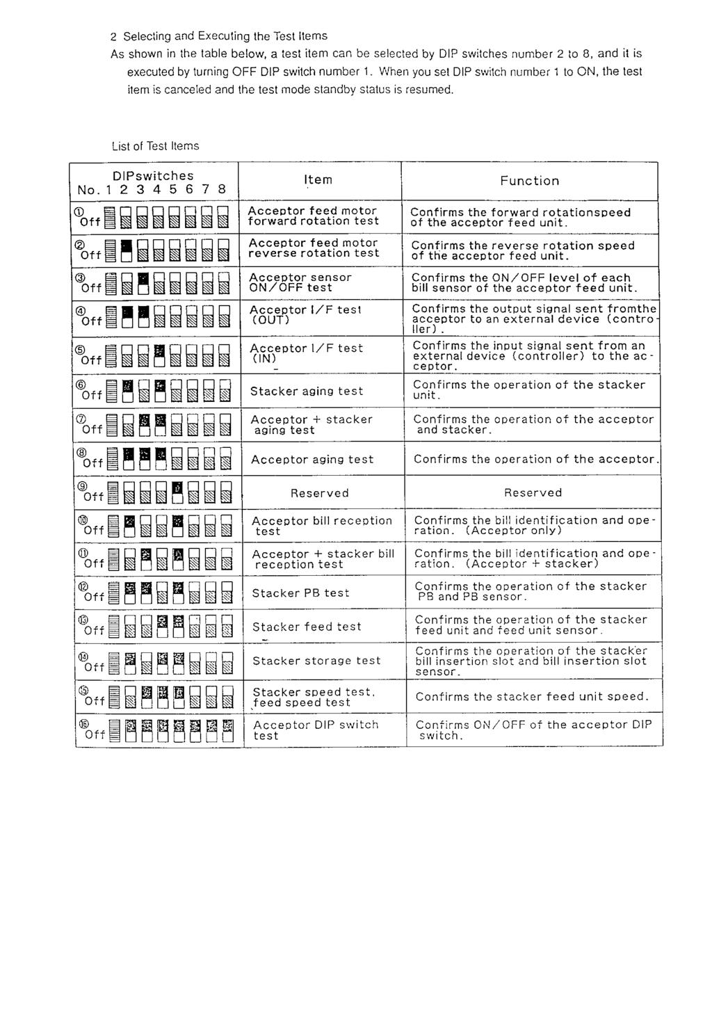
89 2 Selecting and Executing the Test Items As shown in the table below, a test item can be selected by DIP switches number 2 to 8, and it is executed by turning OFF DIP switch number 1. When you set DIP switch number 1 to ON, the test item is cancelled and the test mode standby status is resumed. List of Test Items DIP switches No Item Acceptor feed motor forward rotation test Acceptor feed motor reverse rotation test Acceptor sensor ON / OFF test Acceptor I/F test (OUT) Acceptor I/F test (IN) PB aging test Function Confirms the forward rotation speed of the acceptor feed unit. Confirms the reverse rotation speed of the acceptor feed unit. Confirms the ON / OFF level of each bill sensor of the acceptor feed unit. Confirms the output signal sent from the acceptor to an external device (controller). Confirms the input signal sent from an external device (controller) to the acceptor. Confirms the operation of the PB unit. Acceptor + PB aging test Confirms the operation of the acceptor and PB. Acceptor aging test Confirms the operation of the acceptor. Reserved Acceptor bill reception test Acceptor + stacker bill reception test PB test PB feed test Reserved PB speed test, feed speed test Acceptor DIP switch test Reserved Confirms the bill identification and operation. (Acceptor only) Confirms the bill identification and operation. (Acceptor + stacker) Confirms the operation of the PB and PB sensor. Confirms the operation of the PB feed unit and feed unit sensor. Reserved Confirms the PB feed unit speed. Confirms ON / OFF of the acceptor DIP switch. PERFORMANCE TEST Japan Cash Machine Co., Ltd. Class EBA-10-PB Chapter 7 Date Dwg No Page 2
90
91 3 Description of Test Items (1) Acceptor feed motor forward rotation test Confirms the forward rotation speed of the acceptor feed unit. The feed speed is displayed on the VM-450. VEND1 and VEND2 turn on. Fast feed speed VEND2 and VEND3 turn on. Correct feed speed VEND3 and VEND3 turn on. Slow feed speed PERFORMANCE TEST (2) Acceptor feed motor reverse rotation test The feed speed is displayed on VM-450 in the same manner as (1). Acceptor feed motor forward rotation test. Japan Cash Machine Co., Ltd. Class EBA-10-PB Chapter 7 Date Dwg No Page 3
92 (3) Acceptor sensor ON / OFF test Confirms the ON / OFF level of each bill sensor of the acceptor feed unit. Note: You can perform this test only after performing the automatic adjustment. When a bill is fed into the feed route of the acceptor, the VEND1 to VEND4, ABN and STKF LEDs of VM-450 will light up. (This test only confirms the operation of sensors which detect whether a bill is present or not.) (4) Acceptor I/F test (OUT) PERFORMANCE TEST This test allows you to confirm the operation of the output signal line from the acceptor to the external device (controller) according to the lighting sequence of the VM-450 LEDs. Japan Cash Machine Co., Ltd. Class EBA-10-PB Chapter 7 Date Dwg No Page 4
93 The signals sent from the acceptor are sequentially indicated by the VEND1, VEND2, VEND3, VEND4, ABN and STKF LEDs of VM-450. (Make sure the BSY LED is lit.) VM-450 (5) Acceptor I/F test (IN) This test allows you to confirm the operation of the input signal line from the external device (controller) to the acceptor according to the lighting sequence of the VM-450 LEDs. When the ENABLE/DISABLE, REJ and ACK switches are turned on at VM-450, the acceptor will output a signal to turn on the LEDs of VM-450. PERFORMANCE TEST When the ENABLE/DISABLE, REJ and ACK switches are turned on, the VEND2 to VEND4 LEDs will light up. Before performing this test, perform 3-(4) Acceptor I/F test (OUT). Japan Cash Machine Co., Ltd. Class EBA-10-PB Chapter 7 Date Dwg No Page 5
94 (6) Stacker ageing test Confirms the operation of the stacker unit. When an error occurs during the operation of the stacker, the VEND1 to VEND3 LEDs and ABN LED of VM-450 are turned on and the stacker operation is terminated. An error code is displayed depending on the number of times the LED on the CPU board flashes. (See 4-(1) Error Code (Malfunction) List.) (7) Acceptor + stacker ageing test Periodically repeats the series of acceptor and stacker operations. When an error occurs during the operation of the stacker, the VEND1 to VEND3 LEDs and ABN LED of VM-450 are turned on and the stacker operation is terminated. An error code is displayed depending on the number of times the LED on the CPU board flashes. (See 4-(1) Error Code (Malfunction) List.) (8) Acceptor ageing test PERFORMANCE TEST Periodically repeats the acceptor operation. When an error occurs during the operation of the acceptor, the VEND1 to VEND3 LEDs and ABN LED of VM-450 are turned on and the acceptor operation is terminated. An error code is displayed depending on the number of times the LED on the CPU board flashes. (See 4-(1) Error Code (Malfunction) List.) Japan Cash Machine Co., Ltd. Class EBA-10-PB Chapter 7 Date Dwg No Page 6
95 (9) Omitted because this switch is reserved. (10) Acceptor bill reception test Confirms the bill receiving operation of only the acceptor. After the initial operation is completed, a bill can be received and the rate of receiving bills can be confirmed. When the model (ROM) supporting the HI security is tested, bill receiving with the HI security function can be confirmed if you turn on DIP switch No. 8 after the initial operation is completed. Note: Even if DIP switch No. 1 is set to ON, the test mode will not be resumed when this test is executed. VM-450 currency type signal indication Currency type V 1 V 2 V 3 Currency type 1 Currency type 2 Currency type 3 Currency type 4 Currency type 5 Currency type 6 If a bill is not received successfully, check the following items. VM-450 indicates that a bill has been received. The type of currency is indicated by means of the combination of flashing LEDs. a) A bill is not accepted. Acceptor operation error. Check the number of times the LED on the CPU board flashes and repair or replace the necessary parts. (See 4-(1) Error Code (Malfunction) List.) b) A bill is rejected. Acceptor identification unit error. Check the number of times the LED on the CPU board flashes and adjust (clean the identification unit), repair or replace the necessary parts. (See 4-(2) Error Code (Rejecting a bill) List.) PERFORMANCE TEST Note: Do not use bills like the ones below to confirm the bill receiving operation. If you insert such a bill, it will not be identified properly. (a) Bills that are dirty, worn, wet, torn and badly wrinkled. (b) Bills with folded and overlapped corners or edges. (c) Bills that have considerably different cutting dimensions and printing displacement. (d) Bills that are stained or have iron particles on them. Japan Cash Machine Co., Ltd. Class EBA-10-PB Chapter 7 Date Dwg No Page 7
96 (11) Acceptor + stacker bill reception test Confirms the bill reception when the acceptor is equipped with a stacker. After the initial operation is completed, a bill can be received and the rate of receiving bills can be confirmed. When the model (ROM) supporting the HI security is tested, bill reception with the HI security function can be confirmed if you turn on DIP switch No. 8 after the initial operation is completed. Note: Even if DIP switch No.1 is set on ON, the test mode will not be resumed when this test executed. (12) Stacker PB test Confirms the operation of the stacker PB and PB lever sensor. PB lever home position detection: VEND1LED turns on PB unit operates periodically. VEND1 turns on only when the home position detection lever of the PB unit is blocking the photo interrupt of the stacker board. PERFORMANCE TEST (13) Stacker feed test Confirms the operation of the stacker feed, FEED 1 and FEED 2 sensors and stacker reset switch. Japan Cash Machine Co., Ltd. Class EBA-10-PB Chapter 7 Date Dwg No Page 8
TF20 Tray Feeder. Instruction Manual. for JEDEC and IEC Standard Trays
 for JEDEC and IEC Standard Trays Instruction Manual 096-0243-003 Data I/O assumes no liability for errors, or for any incidental, consequential, indirect, or special damages, including, without limitation,
July P Wide Format Stacker User Guide
 July 2009 701P49768 Wide Format Stacker User Guide 2009 Xerox Corporation. All rights reserved. Xerox and the sphere of connectivity design are trademarks of Xerox Corporation in the United States and/or
BakeMax Dough Mini Moulder BMMDM02
 BakeMax Dough Mini Moulder BMMDM02 2 Instruction Manual 1. Preface ------------------------------------------- P2 2. Machine Introduction -------------------------------- P2 3. Machine Specification and
WELCOME. Standard Change Makers, Inc. Changer Maintenance Overview General Maintenance Guide for Standard Change-Makers Machines
 WELCOME Standard Change Makers, Inc. Changer Maintenance Overview - - - General Maintenance Guide for Standard Change-Makers Machines Service Maintenance School Reviewing: The SC System Product Line. The
Operational Manual for the HV-X Validator
 Operational Manual for the HV-X Validator Document #101-0029 12/26/02 ABOUT THIS MANUAL This manual will enable the operator to complete basic maintenance, identify error codes, and perform basic troubleshooting.
Conversion Station Model 711
 Conversion Station Model 711 Automatic Tag Dispenser Guide 3M Library Systems 3M Center, Building 225-4N-14 St. Paul, Minnesota 55144-1000 www.3m.com/library Copyright 2000-2004, 3M IPC. All rights reserved.
Service Manual For the E Ride 26
 Service Manual For the E Ride 26 For: Training Troubleshooting Adjustments Contents 1 Cautions ------------------------------------------------------------------------ 2 Safety Information ----------------------------------------------------------
Magner /35-3 Series Currency Counter. Operator's Manual
 Magner 35-2003/35-3 Series Currency Counter Operator's Manual Magner 35-2003 / 35-3 Series Introduction. The MAGNER 35-2003 / 35-3 is the most advanced Currency Counter available today. MAGNER's Design
F56/F53 Bill Dispenser Unit Maintenance Training Summary
 F56/F53 Bill Dispenser Unit Maintenance Training Summary Contents 1, F56/F53 BDU F56/F53 BDU Outline Description 2, D level command / test program 3, Error codes, Maintenance tracking procedure 4, RAS
Camera Eyepiece. User s Manual. KS035200G4-Ver1.0
 Camera Eyepiece User s Manual Content CHAPTER 1 NOTES AND SAFETY REQUIREMENTS ------------------------- - 1-1.1 Cautions and Notes ------------------------------------------------------------------- -
FW66 FORESTRY WINCH FW66. Owner s Manual 19/02/2016
 FW66 FORESTRY WINCH FW66 19/02/2016 Owner s Manual TABLE OF CONTENTS INTRODUCTION ---------------------------------------------------------------------------------- 2 INTENDED USE -----------------------------------------------------------------------------------
dronium TWO AP DRONE with camera
 dronium TWO AP TM DRONE with camera INSTRUCTION MANUAL WWW.PROTOCOLNY.COM THANK YOU. Thank you for your purchase of Protocol s Dronium Two AP With Camera. You are about to experience the best of what remote
nual k Excella E-1 Open Air Shaker N) manual New Brunswick Excella E-1 Open Air Shaker Operating manual
 manual New Brunswick Excella E-1 Open Air Shaker Operating manual") nual k Excella E-1 Open Air Shaker N) manual New Brunswick Excella E-1 Open Air Shaker Operating manual Copyright 2014 Eppendorf AG, Germany. No part of this publication may be reproduced without the prior
nual k Excella E-1 Open Air Shaker N) manual New Brunswick Excella E-1 Open Air Shaker Operating manual Copyright 2014 Eppendorf AG, Germany. No part of this publication may be reproduced without the prior
Imperial Series. Model IMP-425/525/625/825/1000AP IMD-425/525/625/825/1000AP IMP-1025/1200/1500/2000AP IMD-1025/1200/1500/2000AP
 Service Manual Imperial Series Model IMP-425/525/625/825/1000AP IMD-425/525/625/825/1000AP IMP-1025/1200/1500/2000AP IMD-1025/1200/1500/2000AP Contents of Service Manual 1. Safety Precautions ------------------------------------------------------------------
HOBO Plug Load Logger (UX ) Manual
 Manual") HOBO Plug Load Logger (UX120-018) Manual The HOBO Plug Load logger is designed to monitor energy consumption of AC-powered plug in loads. This compact device can be used as a power meter with its built-in
HOBO Plug Load Logger (UX120-018) Manual The HOBO Plug Load logger is designed to monitor energy consumption of AC-powered plug in loads. This compact device can be used as a power meter with its built-in
09/04 Rev MANUAL Jumbo Stacker. Setup, Service
 09/04 Rev. 3.00-02 MANUAL Setup, Service General... 2 Intended purpose... 2 Mode of operation... 2 System requirements... 3 Safety notes... 3 Setting up... 4 Positioning the stacker... 4 Setting the material
Thank you for purchasing the SC-CONVERSION System 500/600 Conversion Kit. This Kit is available in two different versions:
 Rev. 1 (Jun 30, 2016) Thank you for purchasing the SC-CONVERSION System 500/600 Conversion Kit. This Kit is available in two different versions: Part # 4K01328-FI SC-CONVERSION Conversion Kit with MEI
GMV Super Star. Part List
 GMV Super Star Part List 25 Table of Contents Part List 25 Magazine... 28 Target Retainer... 30 Throwing Table... 31 Main Frame... 32 Turntable... 33 Base... 34 Elevator... 35 Throwing Arm... 36 Motor...
AXIS II RC DRONE WITH CAMERA
 AXIS II RC DRONE WITH CAMERA THANK YOU. Thank you for your purchase of Protocol s Axis II RC Drone With Camera. You are about to experience the best of what remote control flight has to offer. We strongly
Offi ceright Folding Machine DF800/DF900
 Offi ceright Folding Machine DF800/DF900 Operator Guide English Version Table of Contents Chapter 1 Chapter 2 Chapter 3 Introduction Safety...1-1 To The Operator...1-3 About your System...1-3 Machine
MA SERIES Owner's Manual
 TEC MA-600 Series owners programming Manual TEC Electronic Cash Register MA-600-1 SERIES Owner's Manual FCC Notice This equipment has been tested and found to comply with the limits for a Class B digital
Instructions for Continued Airworthiness Talon LC Keeperless Cargo Hook Kit For the AS350 Series. System Part Number STC SR00886SE
 Instructions for Continued Airworthiness Talon LC Keeperless Cargo Hook Kit For the AS350 Series System Part Number 200-261-00 STC SR00886SE 13915 NW 3 rd Court Vancouver Washington 98685 USA Phone: 360-546-3072
USER GUIDE AND MANUAL
 Specifications: Item No.: X5SC Function: up/down, forward/backward, turn left / Right,With GYRO /Flash lights 360-degree 3D special function. Battery: 3.7V 500mAh Li-poly Charging time: About 100 minutes
Troubleshooting Guide 9702 Series
 Troubleshooting Guide 9702 Series Satellite Solutions for Mobile Markets 11200 Hampshire Avenue South, Bloomington, MN 55438-2453 Phone: (800) 982-9920 Fax: (952) 922-8424 www.kingcontrols.com 1305-AUTO
USER S OPERATING AND INSTRUCTION MANUAL
 Grand Rapids, Michigan, U.S.A. 49504-5298 USER S OPERATING AND INSTRUCTION MANUAL MODEL 2005 VARIABLE SLICE THICKNESS BREAD SLICER 2005S20000-CV INDEX Section Description Document No. Page No. SAFETY INSTRUCTIONS
MODEL BE-100HT HEADSET TELEPHONE OWNER S MANUAL PLEASE READ THIS INSTRUCTION MANUAL CAREFULLY.
 MODEL BE-100HT HEADSET TELEPHONE OWNER S MANUAL PLEASE READ THIS INSTRUCTION - 1 - MANUAL CAREFULLY. - 2 - TABLE OF CONTENTS Introduction -------------------------------------------------------------------4
Firmware Version:1.137 Display Version:2.06a. Xrd-384 Stacker Installation Manual
 Firmware Version:1.137 Display Version:2.06a Xrd-384 Stacker Installation Manual 1 Content 1. Safety Precaution 3 2. To use instrument safety 3-4 3. Instruction for use 4 4. Specifications 5 5.Overview
MEDIZINTECHNIK FÜR TIERÄRZTE
 GB Tabel of contents: Operation Instructions Electronic Platfoorm Balances MEDIZINTECHNIK FÜR TIERÄRZTE 1 Technical data 17 2 Fundamental information (general) 18 2.1 Intended use 18 2.2 Inappropriate
AP5K-C Precision AC Double-Pulse Spot Welding Machine User s Manual Shenzhen Will-Best Electronics Co., Ltd
 AP5K-C Precision AC Double-Pulse Spot Welding Machine User s Manual Shenzhen Will-Best Electronics Co., Ltd 1 Content 1. Introduction...3 1.1 Functions...3 1.2 Units of AP5K-C...4 2. The Initial Installation
POWER FACTOR REGULATOR. Computer-12e-xx INSTRUCTION MANUAL ( M / 02A ) (c) CIRCUTOR S.A.
 (c) CIRCUTOR S.A.") POWER FACTOR REGULATOR Computer-12e-xx INSTRUCTION MANUAL ( M 981 606 / 02A ) (c) CIRCUTOR S.A. -------- POWER FACTOR REGULATOR COMPUTER- 12e --------- Page 2 POWER FACTOR REGULATOR COMPUTER- 12e 1.- POWER
POWER FACTOR REGULATOR Computer-12e-xx INSTRUCTION MANUAL ( M 981 606 / 02A ) (c) CIRCUTOR S.A. -------- POWER FACTOR REGULATOR COMPUTER- 12e --------- Page 2 POWER FACTOR REGULATOR COMPUTER- 12e 1.- POWER
Operator s Manual for Morse Heavy-Duty Kontrol-Karrier with 3-Piece Drum Holder
 CONTENTS Page Receiving Procedures.................... 1 Warranty............................. 1 Safety Information..................... 1-2 Machine Description................... 3 Operating Instructions....................
Océ DFS10. Operator Manual
 Océ DFS10 Operator Manual Océ-Technologies B.V. All rights reserved Id: 7241873 Approvals and certifications Safety Europe Approved by Underwriters Laboratories Inc. North America This equipment is listed
INSTRUCTION MANUAL VR HD NANO DRONE
 Age: 14+ INSTRUCTION MANUAL VR HD NANO DRONE Thank you for purchasing our VR HD Nano Drone. Please read the instructions carefully to fully learn about the drone and fly it safely. Save this instructions
LED ROTATION BEAM LIGHT
 LED ROTATION BEAM LIGHT MJ-1018(White) INSTRUCTION MANUAL Thank you for choosing our LED rotation beam light. For the sake of your safety, Please read and follow these instructions carefully and keep this
MAGNER START
 - Contents Important Safety Precautions... 4 Warning... 4 1. START 1-1. Packing List... 5 1-2. Options... 5 1-3. Appearance... 6 2. BASIC OPERATION 2-1 Self-Diagnosis... 7 2-2. Counting Notes... 8 2-3.
MERIGAUGE MODEL 3900 OPERATING INSTRUCTIONS
 99 Washington Street Melrose, MA 02176 Phone 781-665-1400 Toll Free 1-800-517-8431 Visit us at www.testequipmentdepot.com MERIGAUGE MODEL 3900 OPERATING INSTRUCTIONS Meriam Instrument s MERIGAUGE Model
Manual Rotary Heat Sealers. Type: F108TX. List of content : Introduction 2. General description 3. Application 4. Safety precautions 5
 Manual Rotary Heat Sealers Type: F108TX List of content : Page: Introduction 2 General description 3 Application 4 Safety precautions 5 Transport and storage 6 Installation 7 First Set-up 8 Connection
Agilent 16034E Test Fixture
 Agilent 16034E Test Fixture Operation and Service Manual Third Edition Agilent PN 16034-90041 December 1999 Printed in: Japan Notices The information contained in this document is subject to change without
Table of Contents. Installation 2-10 Leveler legs... 2 Controller... 4 Dip-switch Configurations. 5 Wire Harness Installation.. 7
 Table of Contents Installation 2-10 Leveler legs... 2 Controller... 4 Dip-switch Configurations. 5 Wire Harness Installation.. 7 Operation 11-14 Program HOME Position... 12 Program/Reprogram AUTO Level
PTSV403. Camera Parking Assist System. Camera PTSV
 PTSV403 Camera Parking Assist System PTSV403 75545485 Camera Sensor Contents Reasons to choose Steelmate User's Manual Reasons to choose Steelmate -------------------- Disclaimer --------------------------------------------
Quick Installation Guide. MVC-PTZ-23X Indoor/Outdoor 23 PTZ Speed Dome Camera
 MVC-PTZ-23X Indoor/Outdoor 23 PTZ Speed Dome Camera Quick Installation Guide 5101 NW 21st Ave, Suite 210 Fort Lauderdale, FL 33309 www.mace.com (877) 585-6223 Table of Contents 1 QUICK INSTALLATION SPEED
Xerox Nuvera Xerox Production Stacker Operator Manual
 Software Version 11.6 October 2012 702P00782 Xerox Nuvera Xerox Production Stacker Xerox Nuvera 100/120/144/157 EA Production System Xerox Nuvera 100/120/144 MX Production System Xerox Nuvera 200/288/314
TALON Cargo Hook Troubleshooting Guide
 TROUBLESHOOTING GUIDE 125-004-00 Revision 1 As of: August 14, 2009 For all TALON Cargo Hooks TALON Cargo Hook Troubleshooting Guide TALON LC Hydraulic Hook TALON LC Cargo Hook TALON LC Keeperless Hook
VENTO WIFI DRONE WITH LIVE STREAMING CAMERA
 VENTO WIFI DRONE WITH LIVE STREAMING CAMERA INSTRUCTION MANUAL THANK YOU. Thank you for your purchase of Protocol s Vento Wifi Drone with Live Streaming Camera. You are about to experience the best of
FAST POWER FACTOR REGULATOR. Computer-14df - xx - 144a INSTRUCTION MANUAL ( M / 00A ) (c) CIRCUTOR S.A.
 (c) CIRCUTOR S.A.") FAST POWER FACTOR REGULATOR Computer-14df - xx - 144a INSTRUCTION MANUAL ( M 981 611 / 00A ) (c) CIRCUTOR S.A. -------- POWER FACTOR REGULATOR COMPUTER- 14f --------- Page 2 POWER FACTOR REGULATOR COMPUTER-
FAST POWER FACTOR REGULATOR Computer-14df - xx - 144a INSTRUCTION MANUAL ( M 981 611 / 00A ) (c) CIRCUTOR S.A. -------- POWER FACTOR REGULATOR COMPUTER- 14f --------- Page 2 POWER FACTOR REGULATOR COMPUTER-
WP200e Wallbox to CD Changer Adapter
 WP200e Wallbox to CD Changer Adapter Supported Wallbox Models AMI W-40 & W-80 & W-120, 40/80/120 Select AMI WQ-200, 200 Select Rock-Ola 1558 & 500, 160 Select Rock-ola 1555, 200 Select Rowe WRA, WRB &
Pallet Safe: Installation Supplement Rev
 Pallet Safe: Installation Supplement Rev. 4-1-13 Smartscan Incorporated, 33083 Eight Mile Road, Livonia MI 48152 Tel: (248)477-2900 Fax: (248) 477-7453 Web: www.smartscaninc.com SMARTSCAN INCORPORATED
Option Printer. d-color MF201 d-color MF201Plus - MF250 - MF350 PC-405 THEORY OF OPERATION. Code Y
 Option Printer d-color MF201 d-color MF201Plus - MF250 - MF350 THEORY OF OPERATION Code Y109041-4 PUBLICATION ISSUED BY: Olivetti S.p.A. 77, Via Jervis - 10015 Ivrea (TO) Italy Copyright 2008, Olivetti
SERVICE PARTS LIST SPECIFY CATALOG NO. AND SERIAL NO. WHEN ORDERING PARTS. 120V Permanent Magnet Drill STARTING SERIAL NUMBER.
 69(5x) CATALOG NO. SERVICE PARTS LIST SPECIFY CATALOG NO. AND SERIAL NO. WHEN ORDERING PARTS 120V Permanent Magnet Drill 2-20 STARTING SERIAL NUMBER G85A BULLETIN NO. 5-6-00 REVISED BULLETIN DATE Apr.
CM-v-3 module. GSM/GPRS/EDGE communication module for MT880 meters. Technical description
 GSM/GPRS/EDGE communication module for MT880 meters Document code: EAD 028.890.101 Version: V1.01 Language: English Date: 06.03.2015 COPYRIGHT 2011 ISKRAEMECO d.d., Merjenje in upravljanje energije. All
Best Selection for Your Business. Electronic Pricing Scale. User s Manual. (Model: TP-31)
") Best Selection for Your Business Electronic Pricing Scale User s Manual (Model: TP-31) CATALOG 1. Foreword... 2 1.1. Introductions... 2 1.2. Main functions and features... 2 1.3. Specification... 2 1.4.
Best Selection for Your Business Electronic Pricing Scale User s Manual (Model: TP-31) CATALOG 1. Foreword... 2 1.1. Introductions... 2 1.2. Main functions and features... 2 1.3. Specification... 2 1.4.
XSTi Standby UPS. 400VA, 600VA, 800VA Models. User & Installation Manual
 XSTi Standby UPS 400VA, 600VA, 800VA Models User & Installation Manual www.xpcc.com 2015. All rights reserved. (Rev 12/14/15) Table of Contents Package Contents... 3 Product Introduction... 3 Product Overview...
THANK YOU. As with any aircraft, this is a precision flying machine. Treat it well and enjoy all the fun it has to offer, flight after flight.
 WWW. PROTOCOLNY.COM THANK YOU. Thank you for your purchase of Protocol s Dronium One AP With Camera. You are about to experience the best of what remote control flight has to offer. We strongly recommend
Setup Guide. Snackvendor Models 170/ Enterprise Way Bridgeton, MO (314) August,
 August,") Setup Guide Snackvendor Models 170/171 12955 Enterprise Way Bridgeton, MO 63044-1200 (314) 298-3510 August, 1998 1700014 TABLE OF CONTENTS Specifications... ii Electrical Power Requirements... 1 Unpack
Setup Guide Snackvendor Models 170/171 12955 Enterprise Way Bridgeton, MO 63044-1200 (314) 298-3510 August, 1998 1700014 TABLE OF CONTENTS Specifications... ii Electrical Power Requirements... 1 Unpack
Instruction Manual ODY-1765
 INSPIRING IMAGINATION Instruction Manual ODY-1765 We hope you enjoy your purchase of the Stealth NX-2 Drone and use this Instruction Manual to get your drone to take off! Included Contents 1. Stealth NX-2
Wireless Freezer Manual Installation Guide
 Wireless Freezer Manual Installation Guide Doc # 152-11103-01 Revision DRAFT May 2009 Copyrights Copyright 2008 by. All rights reserved. The information in this document is subject to change without notice.
Installation, Operation & Maintenance Manual
 Original Instructions Installation, Operation & Maintenance Manual Sentry IC Indexing Cabinet Automatic Sampling Accessories S-AS-IOM-00462-2 11-17 Do not install, maintain, or operate this equipment without
! CAUTION: Read and follow these instructions.
 OmniLog SAFETY AND INSTALLATION INSTRUCTIONS! CAUTION: Read and follow these instructions. Avoid Contact with Hazardous Live Parts WARNING: Risk of electrical shock. Refer servicing to qualified personnel.
Operational Manual. Spectrophotometer Model: SP-830 PLUS. Metertech Inc. Version 1.07
 Operational Manual Spectrophotometer Model: SP-830 PLUS Metertech Inc. Version 1.07 Metertech Inc. provides this publication as is without warranty of any kind, either express or implied, including, but
PMA 31-G. English. Printed: Doc-Nr: PUB / / 000 / 00
 PMA 31-G English 1 Information about the documentation 1.1 About this documentation Read this documentation before initial operation or use. This is a prerequisite for safe, trouble-free handling and
GIGA Commercial Drone. Owner s Manual. For Owner s Manual updates, warranty information, and support, visit:
 GIGA -6000 Commercial Drone Owner s Manual For Owner s Manual updates, warranty information, and support, visit: www.mota.com/giga-6000 Please read the Owner s Manual before your first flight. It has information
Cutlass Fasteners, Inc. 83 Vermont Ave., Unit 6, Warwick, RI Tel: (401) Fax: (401) cutlass-studwelding.com
 Fax: (401) cutlass-studwelding.com") MODEL : PHM-12 ARC WELD GUN PART NO. : PHM-12 (PHM-12-RS) SERIAL NO. : PLEASE READ THIS OPERATION AND MAINTENANCE MANUAL CAREFULLY BEFORE USING YOUR NEW CUTLASS STUD WELDER. COPYRIGHT CFI 2009 email: sales@
MODEL : PHM-12 ARC WELD GUN PART NO. : PHM-12 (PHM-12-RS) SERIAL NO. : PLEASE READ THIS OPERATION AND MAINTENANCE MANUAL CAREFULLY BEFORE USING YOUR NEW CUTLASS STUD WELDER. COPYRIGHT CFI 2009 email: sales@
Visit us at
 testo 606-2 Instruction manual 99 Washington Street Melrose, MA 02176 Phone 781-665-1400 Toll Free 1-800-517-8431 Visit us at www.testequipmentdepot.com Short manual testo 606-2 11 Short manual testo 606-2
Good Husband Brand Remote Lighting Lifter
 Good Husband Brand Remote Lighting Lifter National Patent Number:200520069085.5 200520075680.X 200520075677.8 200520075679.7 International Patent Number: PCT/CN2006/000409 Product Standard: Q/QABC002-2009
14+ FOR AGES 14 AND UP ITEM NO
 14+ FOR AGES 14 AND UP ITEM NO. 33743 INTRODUCTION Thank you for purchasing this amazing World Tech Toys product. This drone is suitable for indoor and outdoor flight. Please carefully read the entire
SIWAREX FTC-B Weighing Module for Belt Scales Set-up of SIWAREX FTC with SIWATOOL FTC_B
 SIWAREX FTC-B Weighing Module for Belt Scales Set-up of SIWAREX FTC with SIWATOOL FTC_B Quick Guide For modules with order number 7MH4900-3AA01 1 Hardware Requirements... 3 2 Connections... 5 3 SIWATOOL
TABLE OF CONTENTS SERVICE
 Manu ual Treadmill IMPORTANT: Read all instructions carefully before using this product. Retain this owner s manual for future reference. The specifications of this product may vary from this photo and,
ENG. Instruction Manual. Turbo SFcompact. LNS Turbo 203 Turbo Drive Kings Mountain, NC 28086
 Instruction Manual ENG Turbo SFcompact LNS Turbo 203 Turbo Drive Kings Mountain, NC 28086 IMPORTANT READ CAREFULLY BEFORE USE AND KEEP FOR FUTURE REFERENCE. Published: 11/2016 LNS SA 2016 9.900.002.1.EN
1600 Currency counting machines
 600 Currency counting machines user guide DE LA RUE CASH SYSTEMS SIZE AUTO CFA 0 8 9 5 6 Walton Rd, Farlington, Portsmouth Hampshire P06 ITJ Tel: + (0) 9 86 Fax: + (0) 9 58 REFERENCE- TML09 600 De La Rue
Operating Instructions
 M-620 4.01 Operating Instructions for Automatic Actuators for Machine Doors MxP 50/101/300 The Power of New Motor Technologies Certified Quality System ISO 900 1/E N 2 9001 The enterprises Landert-Motoren
Crane Merchandising Systems Parts and Support Phone Numbers:
 This machine has been engineered to our own rigid safety and performance standards. It has been designed to comply with sanitation and health guidelines recommended by the Automatic Merchandising Health-Industry
U28. Name of Parts 1. Drone. Blade Guard. Battery Cover. Drone Body Blade Motor. Body Light. Camera. Landing Gear. Blade Guard Installation Diagram
 Name of Parts 1. Drone Blade Guard Drone Body Blade Motor Body Light Camera Landing Gear Blade Guard Installation Diagram U8 TF Card Installation Diagram . Transmitter Power Switch Throttle/ Up and Down
HRO-50 Water Purifier
 HRO-50 Water Purifier Product Installation & Operation Manual Honeywell Environmental & Combustion Controls (Tianjin) Co., Ltd. Content Important Notes P2 Product Functions P3-P5 Installation Instructions
MET-FAB FABRICATION & MACHINE, INC. P.O. Box 363, Batavia, Ohio Ph. (513) Fax (513)
 Fax (513)") 1 2 MET-FAB FABRICATION & MACHINE, INC. P.O. Box 363, Batavia, Ohio 45103 Ph. (513) 724-3715 Fax (513) 724-1336 The people who can help you with your material handling needs Fact! A note about our references.
1 2 MET-FAB FABRICATION & MACHINE, INC. P.O. Box 363, Batavia, Ohio 45103 Ph. (513) 724-3715 Fax (513) 724-1336 The people who can help you with your material handling needs Fact! A note about our references.
HYDRAULIC DOCK LEVELER OWNERS MANUAL
 HYDRAULIC DOCK LEVELER OWNERS MANUAL 1 HYDRAULIC DOCK LEVELER OWNERS MANUAL 2 TABLE OF CONTENTS Table Of Contents.. Page 2 Koke Hydraulic Leveler Model Information... Page 3 Hydraulic Dock Leveler Installation
Instruction Manual HT 24 BM-D2400 Homogenizer
 Instruction Manual HT 24 BM-D2400 Homogenizer Foreword Thank you for purchasing a HT 24 Homogenizer. This manual contains instructions for the proper operation and care of this instrument. Please read
Electra User s Manual
 Electra User s Manual Help Desk: 1-800-922-8079 Help Desk Hours: M-F 8:00 a.m. to 5:00 p.m. EST Operating instructions for the PI-21 printer with the CI-201 Keypad Unit. Open the Door of your machine to
Adam Equipment LBH SERIES. (P.N , Revision B2, January 2010)
") Adam Equipment LBH SERIES (P.N. 700660113, Revision B2, January 2010) Adam Equipment Company 2010 Easy Reference: Model name of the scale: Serial number of the unit: Software revision number (Displayed
Adam Equipment LBH SERIES (P.N. 700660113, Revision B2, January 2010) Adam Equipment Company 2010 Easy Reference: Model name of the scale: Serial number of the unit: Software revision number (Displayed
PE45 AMAZON MONKEY BARS OWNER'S MANUAL
 PE45 AMAZON MONKEY BARS OWNER'S MANUAL WARNING! The disassembled product may contain small parts which pose a choking hazard to children under 3. IMPORTANT: This product may contain sharp points and small
NORTHWESTERN UNIVERSITY PROJECT NAME JOB # ISSUED: 03/29/2017
 SECTION 12 2113 - LOUVER BLINDS PART 1 - GENERAL 1.1 RELATED DOCUMENTS A. Drawings and general provisions of the Contract, including General and Supplementary Conditions and Division 01 Specification Sections,
GT p HD FPV 4 Channel RC Quadcopter. Quadcopter Overview Remote Control Overview
 GT-4160 720p HD FPV 4 Channel RC Quadcopter 1 2 3 4 5 6 7 8 9 10 11 12 13 Quadcopter Overview Remote Control Overview Headless Mode Explained Remote Control Battery & Pairing Remote Control Mode FPV Screen
Blender. Instruction Manual
 Blender Model BL-020B Instruction Manual Version 1 3115 Pepper Mill Court, Mississauga, ON, L5L 4X5 4450 Witmer Industrial Estates, Unit 4, Niagara Falls, NY, 14305 1-800-465-0234 www.omcan.com Table of
Snack Vendor. PosiVend. Models 159, 160, 172, 173, 452, 453, 467, 490, 491
 1720007 Models 159, 160, 172, 173, 452, 453, 467, 490, 491 GPL PosiVend Snack Vendor RT INSEINS CO LY ON E MAK YOURION LOW CT BE SELE RNED GE AN CH TU RE RT INSE SE, 10p PLEA, 5p 1 2p 1p, 50p, 20p, INS
ecosphere water purifier 3in1 USER MANUAL
 ecosphere water purifier 3in1 USER MANUAL TABLE OF CONTENTS System Components 3 Function Overview 4 How to Set up Your Purifier 6 3in1 Cartridge Set Up 7 Initial Run 8 Use 8 Purified Water 8 Tap Water
Storm Drone 6 GPS DEVO 7 Setup for NAZA-M Lite
 DEVO 7 Setup for NAZA-M Lite Step 1 - Set Fixed ID on the transmitter! Skip this part if you have a brand new Storm Drone 6 GPS, we have already done before we ship. 1. 2. 3. 4. 5. 6. 7. 8. 9. Turn on
USER MANUAL FOR MORE INFORMATION
 USER MANUAL FOR MORE INFORMATION Visit us online at force1rc.com for product information, replacement parts and flight tutorials. ATTENTION: BEFORE FLYING YOUR DRONE, PLEASE WATCH THIS FLIGHT INSTRUCTION
KAPTUR GPS WI-FI DRONE WITH HD CAMERA
 KAPTUR GPS WI-FI DRONE WITH HD CAMERA THANK YOU. Thank you for your purchase of Protocol s Kaptur GPS Wi-Fi Drone with HD Camera. You are about to experience the best of what remote control flight has
FTW 175 Wireless Monitoring System Reference Manual Part Number
 FTW 175 Wireless Monitoring System Reference Manual Part Number 7911751 SERIAL NUMBER Flash Technology, 332 Nichol Mill Lane, Franklin, TN 37067 www.spx.com/en/flash-technology (615) 261-2000 Front Matter
SERVICE PARTS LIST DEEP CUT BANDSAW D51C BULLETIN NO CATALOG NO SEE PAGE 3 FOR FASTENER TORQUE CHART
 = Part number change from previous service parts list. SPECIFY CATALOG NO. AND SERIAL NO. WHEN ORDERING PARTS DEEP CUT BANDSAW CATALOG NO. 232-20 SERVICE PARTS LIST STARTING SERIAL NO. D5C REVISED BULLETIN
Quick Guide. CSN950 MultiHead Dimensioner _v2d_MAN_QG_CSN950MH_EN
 Quick Guide CSN950 MultiHead Dimensioner File: 20160406_v2d_MAN_QG_CSN950MH_EN CSN950 MultiHead Quick Guide Table of Contents 1. Safety Instructions... 2 Safety and General Precautions... 2 2. Specifications
DH18 Pizza Warmer Instruction Manual
 DH18 Pizza Warmer Instruction Manual Version 2.1 3115 Pepper Mill Court, Mississauga, ON, L5L 4X5 4450 Witmer Industrial Estates, Unit 4, Niagara Falls, NY, 14305 1-800-465-0234 www.omcan.com Table of
User Manual Interroll Cassette Type 6C L, U, CD, T, W and C profile
 User Manual Interroll Cassette Type 6C L, U, CD, T, W and C profile Version 1.1 (06/2016) en-us Manufacturer Interroll Joki A/S Hammerholmen 2-6 2650 Hvidovre Denmark Telephone: +45 36 88 33 44 Fax: +45
Industrial flue gas probes. Instruction manual
 Industrial flue gas probes Instruction manual 2 1 Contents 1 Contents 1 Contents... 3 2 Safety and the environment... 4 2.1. About this document... 4 2.2. Ensure safety... 4 2.3. Protecting the environment...
2000 User/ Installer Guide
 MODELS SH 16, 30, 50, 75, 100 Now Up To 14 Digit Dialing 2000 User/ Installer Guide Select Entry Systems This page intentionally blank. TABLE OF CONTENTS 1.0 INTRODUCTION... 1 1.1 ENVIRONMENTAL... 1 1.2
Weighing Indicator YH-T3. User Manual
 Weighing Indicator YH-T3 User Manual Content CHAPTER 1 MAIN SPECIFICATION......-2- CHAPTER 2 INSTALLATION......- 3-2.1 FRONT AND BACK VIEW OF INDICATOR... - 3-2.2 CONNECTING LOAD CELL TO INDICATOR...-
BESTMOVE STANDING TRANSFER AID
 BESTMOVE STANDING TRANSFER AID L.L.C. MODELS BestMove 400 BestMove 450 PRODUCT FEATURES *BestMove 450 shown Ensure the product has been assembled according to the instructions in this manual. OPERATING
MICRO WELD MODEL GP1, GP2 CERAMIC FUSION BUTT WELDERS MICRO PRODUCTS COMPANY SERVICE MANUAL
 MICRO WELD MODEL GP1, GP2 CERAMIC FUSION BUTT WELDERS MICRO PRODUCTS COMPANY SERVICE MANUAL 1 TABLE OF CONTENTS 1.0 SPECIFICATIONS 2.0 GENERAL OPERATING INSTRUCTIONS 3.0 BASIC OPERATING PARTS 4.0 BASIC
INSTALLATION MANUAL AND OPERATING INSTRUCTIONS
 INSTALLATION MANUAL AND OPERATING INSTRUCTIONS MD41-( ) Series GPS Annunciation Control Unit for Garmin GNS 430/530 VHF Communication and Navigation Management System MD41-1469 28vdc Horizontal Mount MD41-1479
Revision 1 RAM ELEVATORS. Elevator Electrical Planning Guide. RAM Manufacturing Ltd
 RAM ELEVATORS Elevator Electrical Planning Guide This guide is intended for people with an understanding of electricity. If you are not, please consult a licensed electrician as errors in application of
USER S OPERATING AND INSTRUCTION MANUAL
 Grand Rapids, Michigan, U.S.A. 49504-5298 USER S OPERATING AND INSTRUCTION MANUAL MODEL 777-N VARIETY SLICER 0777S20000-CV3 INDEX Section Description Document No. Page No. SAFETY INSTRUCTIONS -------------------------------