DRAFT TECHNICAL MEMORANDUM: DIVERGING DIAMOND INTERCHANGES
|
|
|
- Theodore Briggs
- 5 years ago
- Views:
Transcription

1 PHX C DRAFT TECHNICAL MEMORANDUM: DIVERGING DIAMOND INTERCHANGES Note: This document presents a planning level assessment of the feasibility of various improvement strategies for consideration when developing MAG s NexGen RTP. The RTP process would include further technical evaluation and vetting of the strategies with stakeholders and the public. All Rights Reserved, 2010
2 Table of Contents 1.0 OVERVIEW WHAT IS A DDI? DESIGN AND OPERATING PARAMETERS OF A DDI POTENTIAL DDI LOCATIONS EVALUATION APPROACH EVALUATION RESULTS Detailed Screening of Potential DDI Locations Evaluation of Potential Feasible DDI Locations ASSESSMENT OF PERFORMANCE AND FINAL SELECTION RE ROUTING EXISTING TRAFFIC VOLUMES TO SIMULATE DDI OPERATING CONDITIONS OPERATIONAL DELAY AND SPEED CHANGES DUE TO POTENTIAL CONVERSION... 8 Attachments Attachment A Attachment B Attachment C Evaluation of Potential Locations for Diverging Diamond Interchanges Preliminary Engineering Plan Drawing for Potential E. Princess Dr/N. Pima Rd DDI Conversion Preliminary Conceptual Engineering Drawings: Conversion of Selected Urban Diamond Interchanges to Diverging Diamond Interchanges List of Figures Figure 1 Typical Tight Urban Diamond Interchange (TUDI)... 1 Figure 2 Typical Diverging Diamond Interchange (DDI) 2 Phase Operation... 2 Figure 3 Typical Conflict Points for Urban Diamond and Diverging Diamond Interchanges... 3 Figure 4 Typical Single Point Urban Interchange (SPUI)... 4 Figure 5 Potential Locations for Diverging diamond Interchanges (DDIs) Selected for Additional Review... 9 List of Tables Table 1 Potential Diverging Diamond Interchange (DDI) Conversions for Capacity Improvements... 9 Table 2 Comparison of Operational/Capacity Parameters: Standard Diamond Interchange v. Diverging Diamond Interchange (DDI)... 9 TECHNICAL MEMORANDUM Page i of i
3 1.0 OVERVIEW MAG is considering construction of diverging diamond interchanges (DDIs) at select existing (and potentially future) interchange locations within the CPHX study area. 1 These locations have been evaluated to ascertain whether a DDI would facilitate more efficient and expedited traffic flow along major arterials crossing the freeways. Wilson & Company conducted preliminary planning and engineering studies to assess its applicability and suitability for DDIs. The objective of this activity was to (1) determine the feasibility of constructing a DDI at the select locations, (2) identify potential fatal flaws; and (3) establish a preliminary probable cost to construct. 1.1 WHAT IS A DDI? DDIs are a variant of the urban diamond interchange, which has two, two-phase signalized intersections with each serving a separate on/off ramp and crossroad movements (Figure 1). Signal control is developed to minimize the number of vehicles queuing between ramp signals, and signals generally are managed together as one system. The tight urban diamond interchanges (TUDI) design is a compressed diamond interchange. The signalized intersections are more closely spaced and traffic flow, clearance times, and turning speeds are similar to a conventional at-grade intersection. Typically, a four-phase signal control procedure with overlapping cycles is required at both intersections. The TUDI is most beneficial in urban and suburban areas where right-of-way (ROW) constraints exist and simplicity of operation is important, as it is easier for drivers to navigate. As such, many of the interchange treatments in the CPHX study have been constructed as TUDIs. FIGURE 1 TYPICAL TIGHT URBAN DIAMOND INTERCHANGE (TUDI) The DDI is designed to direct the two opposing traffic flows on the arterial street to temporarily cross over to the opposite side of the roadway. This action occurs between the traditional ramp terminal pointes of the TUDI (Figure 2). The DDI design allows left-turning traffic on the crossing arterial to proceed to the freeway on-ramp during a signal phase that precludes potential conflicts with opposing traffic flows. Because a left-turn cycle is not required to facilitate access to the on-ramp, the interchange operation requires only a two-phase signal control; the third phase the protected or dedicate left-turn phase has been eliminated. As shown in Figure 2, during one phase, vehicles shift over to the opposite side of the roadway, and left-turning vehicles proceed unhindered to the freeway on-ramp. Through vehicles traveling in the opposite direction are stopped. Left-turning vehicles from the freeway off-ramp are stopped or required to yield, depending on traffic volumes at the intersection. During the second phase, the vehicle crossover flow is stopped by the signal, as are right-tuning vehicles from the freeway off-ramp. Vehicles previously stopped to accommodate the crossover are given green to continue through the intersection. All left-turning vehicles coming from the freeway off-ramps are given green (or free to pass through a yield sign) to continue unhindered to the second signal has now changed to green. Two-phase signal control reduces delay time, resulting in a substantial increase in intersection throughput or interchange capacity. The DDI design works best where there are heavy left-turn movements onto or off freeway ramps and/or if through movements are unbalanced during peak hours. The signal phasing shown on Figure 2 works particularly well, if there are balanced, heavy left-turn volumes at the interchange. Under the second condition, where unbalanced, through traffic movements on the cross street dominate in the peak-hour, there is an 1 The DDI also is referred to as the Double Crossover Diamond (DCD) Interchange, reflecting the shifting of traffic from the right side of the roadway to the left side, then back to the right side. TECHNICAL MEMORANDUM Page 1 of 11

4 FIGURE 2 TYPICAL DIVERGING DIAMOND INTERCHANGE (DDI) 2 PHASE OPERATION PHASE I PHASE II alternate phasing sequence that clears the through movements at both signalized intersections. The potential benefits and advantages of DDIs are as follows: Simple/unopposed left- and right-turns from all directions, specifically including a free-flow left-trun from the crossing street to the freeway, permitting substantially higher left-turn movements to be accommodated both onto and off the limited access highway or freeway; 2 Better signal network synchronization only two phases needed, and shorter cycle lengths result in reduced delay; Increases the capacity of turning movements (left-turns) to/from freeway ramps Minimizes the need to widen bridge/overpass for more lanes, thereby may reduce project costs; Lanes with multiple assignments in all directions (i.e., opposing through lanes serve also as left-turn lanes and receivers of left-turning vehicles from the freeway); Better storage between the ramp terminals; U-turns from highway are accommodated well with reduced impedance of flow (similar to SPUI), which also can aid incident management and maintenance of traffic plans for nearby construction; Can create a calming effect on overall traffic operations reduced speed can result in fewer, less severe crashes; Wrong-way movements to/from freeway ramps are virtually eliminated; Theoretically improves pedestrian and bicycle safety; and 2 It is important to note that all turning movements may encounter the need to yield, depending on the number of lanes provided and presence of pedestrian/bicycle traffic. However, it is critical for the left turn to be free flow, as this is the defining concept of the DDI and its principal advantage. Refer to Missouri s Experience with a Diverging Diamond Interchange, Lessons Learned, Missouri Department of Transportation, Rpt #OR , May TECHNICAL MEMORANDUM Page 2 of 11
5 CENTRAL PHOENIX TRANSPORTATION FRAMEWORK STUDY Fewer conflict points than the TUDI, which has 30 compared to the DDI s 18 (considering only the two ramp intersections and not the freeway/ramp splits, the TUDI has 26 conflict points and the DDI has only 14 (Figure 3); and Better sight distances. FIGURE 3 TYPICAL CONFLICT POINTS FOR URBAN DIAMOND AND DIVERGING DIAMOND INTERCHANGES Diverging Merging Crossing Source: Adapted from Figure 1.1 and 1.2 in Missouri s Experience with a Diverging Diamond Interchange Lessons Learned, Missouri Department of Transportation, Rpt #OR , May, For existing interchanges, DDIs have additional benefits related to retrofitting: Existing bridge generally can be used on- and off-ramps operate more efficiently, minimizing the need for multiple lanes; Additional ROW rarely needed (for conversion of urban diamond interchanges); Offers the opportunity to add bus crossover lanes on the left-turn on-ramp to facilitate direct access to/from P&R/Transit Center located adjacent to the freeway; Construction time is reduced, as bridge replacement usually is not required; and Maintenance of traffic is simplified during construction, as removal of the existing bridge is not required. There are certain disbenefits or disadvantages to the DDI design: If through traffic volumes on the crossing arterial are high, the slowing of traffic, due to crossover, may dictate examining other interchange design treatments; DDI crossover design, requiring driver to shift to the left side of the roadway, is contrary to driver expectations public education campaign can minimize this issue; Traffic exiting the freeway via off-ramps cannot re-enter the freeway, i.e., traffic cannot proceed straight through to an opposite on-ramp, which also eliminates the ability to integrate the interchange design with one-way frontage roads; Due to crossover design, drivers passing through the DDI must operate at a lower speed (generally, 35 miles per hour) [Note: The corollary to this is fewer, less severe crashes, as noted above]; When pedestrians are present, the requirement to signalize for safe crossing can negatively influence interchange operations; A DDI cannot be placed where other signalized intersections or driveways are too close, because of the potential for vehicle at these nearby locations to backup into the interchange. TECHNICAL MEMORANDUM Page 3 of 11
6 The Single-Point Urban Interchange (SPUI) is another interchange design treatment common to the Phoenix metropolitan area. This design requires the least amount of real estate, but the bridges are larger and more expensive to construct. The SPUI design has only one signal controlling all ramp and crossroad traffic movements (Figure 4). A three-phase signal control commonly is used to control traffic at a SPUI. Signal progressions accommodate leading left-turn and through movements for the crossroad and left-turn movements for the ramps. Right-turn movements for the ramps can be signal or yield controlled. The SPUI design also reduces the number of conflict points compared with a TUDI, 24 v. 30 (20 v. 26, considering only the two ramp intersections). Both the SPUI and DDI improve operational efficiency of an intersection. Typically, the SPUI is most valuable, when there are high arterial volumes and high left-turn volumes and where available right-of-way is constrained or can be secured only at a premium cost. The DDI increases in value as ramp volumes increase, i.e., the DDI design is most beneficial when arterial volumes are lower and ramp volumes are heavy and where a wider freeway right-of-way footprint is available. A comparative study was undertaken to evaluate the DDI relative to the TUDI and SPUI, utilizing Synchro 7, SimTraffic, and VISSIM 4.2 traffic modeling software. Those conducting the study tested various traffic volume scenarios to gain better understanding regarding the affect each deign has on traffic flow. The conclusion resulting from this study is the DDI provides better operations than the TUDI with fewer lanes in the bridge area, and the higher the ramp volume, the more benefit attained and the DDI far outperforms the diamond interchange and the SPUI under all scenarios [with protected phasing], even with fewer lanes DESIGN AND OPERATING PARAMETERS OF A DDI There are certain operational and design parameters that generally characterize a DDI; however, some involve acceptable ranges rather than concrete values. The following parameters have been determined through a review of several sources, including departments of transportation, Federal Highway Administration, and presentations addressing the design and operation of DDIs to improve intersections efficiency and capacity. 4 Other parameters, relating to signage and signal phasing are subject to greater interpretation and responsive to the specific site conditions and traffic volumes. DESIGN SPEED: 10 miles per hour (mph) slower than crossing street speed FIGURE 4 TYPICAL SINGLE POINT URBAN INTERCHANGE (SPUI) 35 mph or lower mph WB-67 design vehicle should be able to proceed at 20 mph and make all turn movements at 15 mph A Comparative Analysis of Diverging Diamond Interchange Operations, Steven B. Speth, PE, Oregon ITE. Sources: Engineering Policy Guide, Diverging Diamond Interchanges, Missouri Department of Transportation; UDOT Lessons Learned, Bangerter Hwy & SR 201, Presentation May 9, 2012, H.G. Kunzler and Nicole Williams, H.W. Lochner; Double Crossover Diamond Interchange, Federal Highway Administration TechBrief (FHWA HRT ), October 2009; Diverging Diamond Interchange 101, Presentation: 14thAnnual ACEC KY FHWA KYTC Partnering Conference, Scott Wolf, Federal Highway Administration, August 11, 2009; To Go Left, Turn Right, Innovative Intersection/Interchange Design, Presenation VTCA Conference, M. Doctor, et al, April 20, 2012; Alternative Intersections/Interchanges: Informational Report (AIIR), FHWA Report (FHWA HRT ), April WB 67 design vehicle is an Interstate Semitrailer, 13.5' high, 8.5' wide and 73.5' long with a 53 foot trailer. The Geometric Design of Highways and Streets Handbook published by the American Association of State Highway and Transportation Officials (AASHTO) that this truck should generally TECHNICAL MEMORANDUM Page 4 of 11
7 INTERCHANGE DESIGN: Signalized intersection and driveways cannot be too close Crossing angle of travel lanes: 30 degrees minimum Median width: Generally increased to allow for flaring required for reverse curves on the interchange approaches Lane storage: Ramp crossover spacing (i.e., distance between ramp terminal intersections) sufficient to accommodate forecast vehicle queue (500- to 850-foot minimum) Ramp terminal intersection to adjacent intersection 1,000-foot minimum or consistent with VISSIM analysis Glare screens are desirable for opposing traffic lanes Lane Width: 15 feet for a WB-67 design vehicle Sidewalk Width: 5 feet minimum, if there is at least 2 feet separation from the curb 6 feet minimum, if located adjacent to the curb 8 feet, if bicycle traffic will be present Wider sidewalks may be necessary, depending on the volume of pedestrian and bicycle traffic Sidewalks must comply with Americans with Disabilities Act Accessibility Guidelines. Typical Design Radii: Design speed between 25 and 30 mph Typically in the 150- to 300-foot range (see below) Based on WB-67 design vehicle Source: Diverging Diamond Interchange 101, Presentation: 14thAnnual ACEC KY FHWA KYTC Partnering Conference, Scott Wolf, Federal Highway Administration, August 11, be the minimum size design vehicle considered for intersections of freeway ramp terminals with arterial crossroads that carry high volumes of traffic and/or that provide local access for large trucks. TECHNICAL MEMORANDUM Page 5 of 11
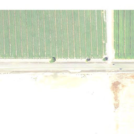
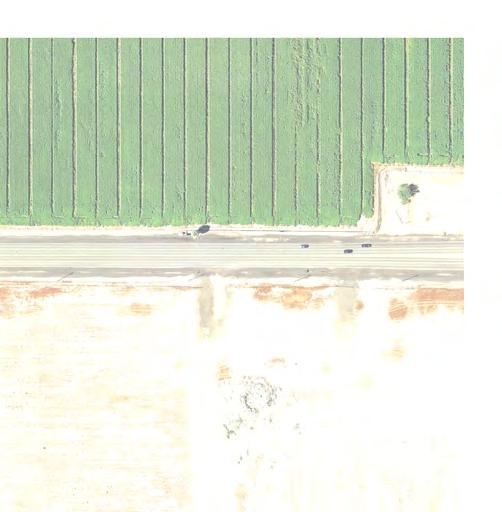
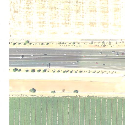
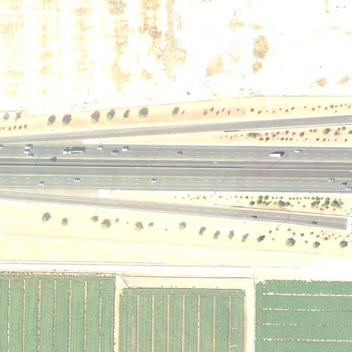
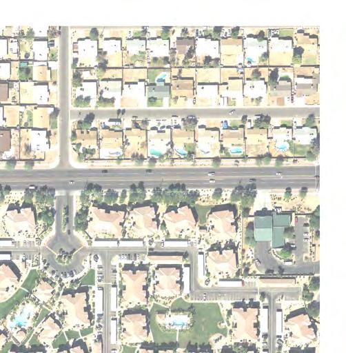
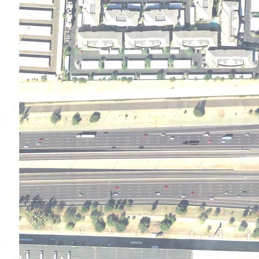
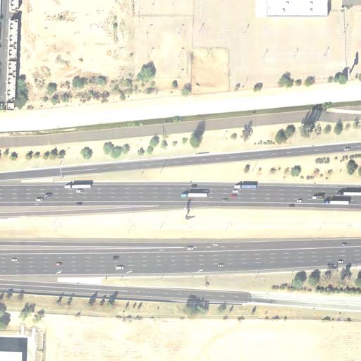
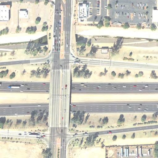
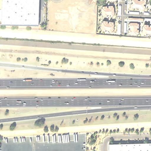
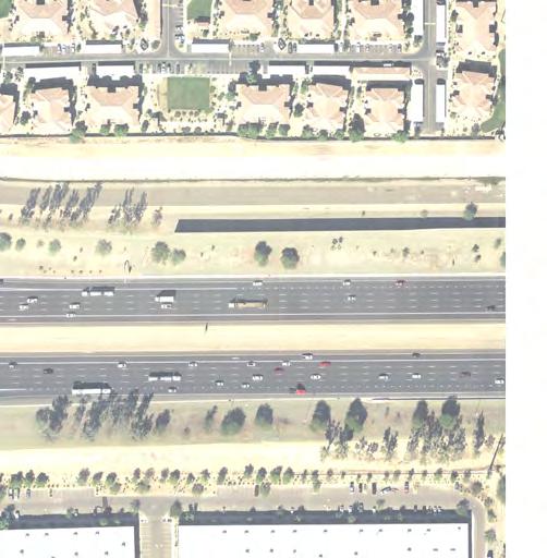
8 2.0 POTENTIAL DDI LOCATIONS This evaluation was conducted to be a planning-level tool sufficiently flexible to apply to the entire freeway network in the CPHX study area. It is anticipated that more detailed evaluations will be added with future iterations addressing this subject. The evaluation was accomplished in three steps: Identify desirable characteristics for locating DDIs; Develop an approach for identifying and evaluating potential locations; Applying the framework and summarize results. 2.1 EVALUATION APPROACH The evaluation of locations potentially suitable for considering construction of a DDI was accomplished through three screenings. The initial screening was based on a fatal flaw type of assessment that took note of two specific factors considered to be conditions contrary to feasible construction of a DDI at interchange locations on the CPHX freeway network: Locations with frontage roads (e.g., I-17 north of I-10 and many segments of Loop 101; and Single-Point Urban Interchanges (SPUIs) and TUDIs where additional right-of-way did not appear to be available. The second screening examined the suitability of potential locations relative to certain basic geometric and operational attributes of DDIs. There were three criteria employed for this screening: Locations with spacing between ramp terminals of at least 500 feet; 6 Locations with spacing to adjacent intersections or other prominent physical feature (e.g., drainage channel) of at least 500 feet; and Locations where DDIs could be implemented with minimal right-of-way impacts. It is important to note that the conversion of an interchange to a DDI was recommended wherever the interchange design treatment fit the screening criteria. This second level screening was undertaken solely for purpose of identifying where near-term capacity increases to the freeway in the network potentially could be implemented. The first two screenings were predicated on the assumption that additional, more detailed evaluations would occur during subsequent studies and did not preclude retention of existing SPUIs or TUDIs. The results of the first two screenings resulted in the identification of 26 potential locations. These 26 locations represent the starting point for the analysis presented in this Technical Memorandum. The objective of this analysis was to ferret out those locations that represent the best potential opportunity to satisfy near-term capacity improvements EVALUATION RESULTS The 26 locations identified through the two-level screening were examined in greater detail through the application of information gained from field reconnaissance and available aerial photography. The additional analysis presented in this Technical Memorandum considered: site geometrics; operational and design factors; operational attributes under the most current traffic volume data for the location; and assumptions regarding conversion cost and original community investment. 6 7 It should be noted that ramp terminal spacing of less than 500 feet, e.g., feet, may be feasible where available right of way is severely constrained and an appropriate geometry can be achieved for efficient and safe traffic flows. The greater distance of 500 feet was adopted for this analysis, as it offers a more conservative basis for determining feasibility and reflects the predominant conclusion in literature on the subject. The original analysis of potential DDI conversion locations was first presented in the Technical Memorandum titled Central Phoenix Transportation Framework Study Assessment of Alternative Improvements Strategies, CH2MHill, July 2, This Technical Memorandum represents an expansion of the information previously published through the addition of aerial photos for easier reference and understanding of issues. TECHNICAL MEMORANDUM Page 6 of 11
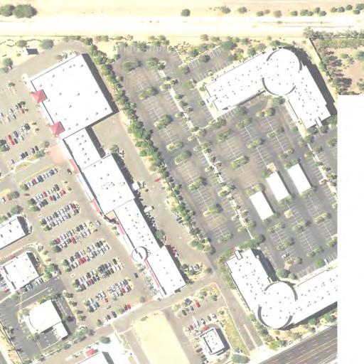
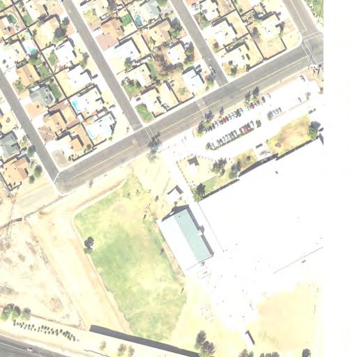
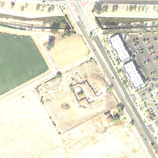
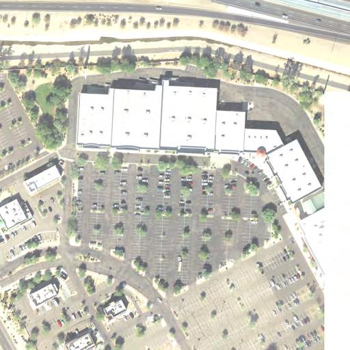
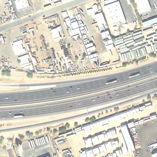
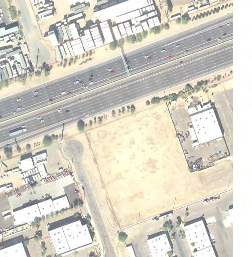
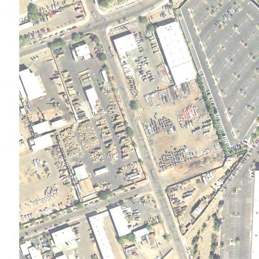
9 2.2.1 DETAILED SCREENING OF POTENTIAL DDI LOCATIONS A review of the 26 potential DDI locations revealed that seven locations were SPUIs. The SPUI design treatment provides a significant operational improvement over the TUDI and in many cases over the DDI, partly because (1) it requires only one signal in the center of the intersection of the crossing arterial 8 and (2) because the design eliminates a signal phase and reduces delay. As noted above, this interchange design treatment also reduces potential conflicts points. Another significant feature of the SPUI is the requirement for a relatively narrow right-of-way, which reduces the cost to construct. That being said, the primary disadvantage of the SPUI is the high construction cost associated with bridging. The essence of the design prohibits a center support structure when the intersection is overpassed by the freeway (i.e., the freeway crosses over the arterial). A ramp intersection under the freeway requires a long bridge to provide a clear span for the crisscrossing traffic pattern. Single-span overpass bridges at SPUIs typically are 220 feet in length, if interchange ramp turning movements are below the freeway overpass. A SPUI with ramp intersections on a bridge over the freeway also tends to be very wide to accommodate the length and geometry of the paths taken by left-turning vehicles. The result is high costs to construct. Because the SPUI often has been constructed in urban areas, where right-of-way is tightly constrained, the design typically utilizes extensive retaining walls, further adding to the cost. The Missouri Department of Transportation (MoDOT) estimates the SPUI costs approximately $1 to $2 million more to construct than a TUDI. 9 Although SPUI design/construction costs often are partially offset by reduced right-of-way cost, the SPUI still represents a significant investment. For example, MoDOT, which has been at the forefront of DDI research and development in this country, conducted a study to improve the TUDI on Interstate 44 at State Route 13 in Springfield. The Department considered widening the existing bridge to create dual left-turn lanes, replacing it with s SPUI over Interstate 44, or converting it to a DDI. The DDI represented a $6 million savings over the SPUI ($3 million v. $9 million) and could be installed in approximately six months compared to 1.5+ years for the SPUI. Because the SPUI provides a significant advantage over the TUDI and SPUIs represent a high initial investment by the community in the transportation system, replacement with a DDI is not a reasonable action. Few benefits would be gained, if any, relative to traffic flow or safety, and the cost to remove a SPUI would be very high, adding significantly to the cost of the upgrade a DDI would provide. Therefore, the SPUI locations were eliminated from further consideration as sites for DDI conversion. The Loop 101 (Pima Freeway)/N. 64 th Street location is a complete TUDI; however, there are no roadways connecting with the interchange. The City s Capital Improvement Program (CIP) includes design and construction of the segment between the interchange and E. Mayo Boulevard to the south in the period. Design of N. 64 th Street to the north will not occur before the period of the CIP. Because the intent of this current assessment of potential location for DDIs is focused on attaining near-term improvements to system capacity consideration of N. 64 th Street during this initial screening was not warranted EVALUATION OF POTENTIAL FEASIBLE DDI LOCATIONS Subsequent to completion of the screening process, it was determined that 18 of the potential locations were worthy of future consideration. The original 26 and the selected 18 locations are shown graphically in Figure 5. The selected 18 locations are listed in Table 1. Attachment A to this Technical Memorandum presents detailed information regarding the 18 locations identified as potentially suitable for conversion to a DDI. The attachment includes information relating to the locational attributes at each site and provides aerial and street-level photographs (as appropriate) to aid in understanding site conditions. Site-specific information, relating to recommended actions, is presented, including caveats or other considerations that may influence development of a DDI as a capacity-enhancing improvement. For purposes of informing the decisionmaking process, Attachment B contains a preliminary engineering drawing for DDI conversion at the E. Princess Drive/N. Pima Road intersection on Loop 101/Pima Freeway, although the City of Scottsdale has opted not to implement the conversion at this time. It is important to note that potential 8 9 Signalization involves four phases, if through movements connecting frontage roads are accommodated. Design of Single Point Urban Interchanges, Research Development and Technology (RDT), Missouri Department of Transportation (MoDOT), Brief, RI , RDT , April, TECHNICAL MEMORANDUM Page 7 of 11
10 improvements at recommended locations may be precluded or complemented by other actions, such as extension of the METRO Light Rail system, the regional light rail transit (LRT) line. Therefore, additional, more detailed engineering studies will be necessary to establish the feasibility and desirability for converting the TUDIs to DDIs. Any further study to implement recommendations in this document should be coordinated with regional and local planning activities and transportation improvement projects. 3.0 ASSESSMENT OF PERFORMANCE AND FINAL SELECTION The original 26 locations identified through the two-level screening were examined in greater detail and subsequently narrowed down to 18 potential locations worthy of future consideration in an assessment of potential improvement scenarios for the CPHX freeway system. This section discusses two additional analyses undertaken to evaluate the feasibility of converting existing interchanges to DDIs. A traffic simulation analysis was conducted to assess the effects of re-routing existing traffic volumes at the selected diamond interchanges to reflect DDI operating conditions. A capacity analysis was conducted to permit comparison of total delay, stops per vehicle, and average speed differences between the two interchange types. 3.1 RE ROUTING EXISTING TRAFFIC VOLUMES TO SIMULATE DDI OPERATING CONDITIONS The most significant adjustment that would be associated with conversion to a DDI design treatment is the shifting of vehicles to the opposite side of the crossing street at the ramp terminal intersections (refer to Figure 2). Once through the ramp terminal intersections on the crossing street, left-turning vehicles proceed unhindered to the freeway on-ramp. Through vehicles traveling in the opposite direction are stopped, and left-turning vehicles from the freeway off-ramp are stopped or required to yield, depending on traffic volumes at the intersection. During the second phase, the vehicle crossover flow is stopped at the signal, while right-tuning vehicles from the freeway off-ramp may be stopped or required to yield. Opposing traffic, previously stopped to accommodate the crossover, continues through the intersection. All left-turning vehicles coming from the freeway off-ramp continue unhindered to the second signal at the opposite end of the DDI. 3.2 OPERATIONAL DELAY AND SPEED CHANGES DUE TO POTENTIAL CONVERSION The 18 locations selected as potentially suitable for conversion to a DDI, based on the three-level screening process, are listed in Table 2. A capacity analysis of each location was conducted using Synchro software, which is based on methodologies outlined in Highway Capacity Manual The analyses permitted comparison of operations of the original Diamond-type interchanges with DDI operations relative to overall level of service (LOS), as defined by improvement in travel delay, stops per vehicle, and average speed. Table 2 highlights eight potential DDI conversion locations deemed to be reasonably feasible to proceed with development of preliminary conceptual engineering layouts: the next step forward in the planning process. The eight potentially feasible sites were determined by identifying whether or not improvement (or, at the least, no degradation) resulted with implementation of the DDI operating pattern. Three interchange locations (51 st Avenue, 59 th Avenue, and 67 th Avenue) were summarily eliminated, because development of the METRO Light Rail Phoenix West Line in the median of Interstate 10 and the future interchange of the Loop 202/South Mountain Freeway would preclude reconstruction of the interchanges. Table 2 reveals that, in all cases, the DDI results in fewer stops. Those interchange locations expected to experience an increase in overall delay were eliminated. Interchange locations expected to experience little or no increase in average speed also were eliminated from consideration. The remaining eight interchange locations (highlighted in green in Table 2) are expected to experience noticeable improvements relative to two or all three operating criteria. These eight locations were considered potentially feasible for DDI conversion. Preliminary conceptual engineering layouts were developed, and are included for reference in Attachment C. TECHNICAL MEMORANDUM Page 8 of 11
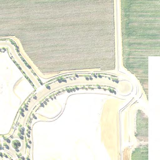
11 CENTRAL PHOENIX TRANSPORTATION FRAMEWORK STUDY FIGURE 5 POTENTIAL LOCATIONS FOR DIVERGING DIAMOND INTERCHANGES (DDIS) SELECTED FOR ADDITIONAL REVIEW NOTE: Preliminary engineering drawings and cost estimates were completed in December, 2011 of a DDI at Princess Dr/Pima Rd. The City of Scottsdale opted to not proceed with conversion at this time. Locations Eliminated from Further Consideration TECHNICAL MEMORANDUM DDI Conversion Policy Guidance Page 9 of 11 May, 2014
12 TABLE 1 POTENTIAL DIVERGING DIAMOND INTERCHANGE (DDI) CONVERSIONS FOR CAPACITY IMPROVEMENTS Freeway I 10 (Papago Fwy) West to East I 10 (Maricopa Fwy) West to East Loop 101 (Aqua Fria Fwy) South to North Loop 101 (Pima Fwy) West to East Segment System Interchange with Loop101/Aqua Fria Fwy to N. 59 th Ave N. 59 th Ave to The Stack (System Interchange of I 10/Papago Fwy with I 17/Black Canyon Fwy) The Split (System Interchange of I 10/Maricopa Fwy with I 17/Maricopa Fwy) to System Interchange with SR 143/Hohokam Expwy System Interchange with US 60/Superstition Fwy to Pecos Stack (System Interchange of I 10/Maricopa Fwy with Loop 202/Santan Freeway) System Interchange with I 10/Papago Fwy to W. Peoria Ave Milepost Begin End MP MP MP MP MP 0.0 W. Peoria Ave to N. 75 th Ave MP 9.1 System Interchange with SR 51/Piestewa Fwy to MP E. Princess Dr 28.9 MP MP MP MP MP 9.1 MP 16.0 MP 35.4 Location N. 83rd Ave [MP 135.7] N. 75th Ave [MP 136.7] N. 67th Ave [MP 137.7] N. 59th Ave [MP 138.7] N. 51st Ave [MP 139.7] N. 43rd Ave [MP 140.7] E. University Dr/ S. 32nd St [MP 151.5] W/E Elliot Rd [MP 157.9] W/E Warner Rd [MP 158.9] W/E Ray Rd [MP 159.9] W/E Chandler Blvd [MP 160.9] W. Thomas Rd [MP 1.74] W. Indian School Rd [MP 2.75] W. Bethany Home Rd [MP 4.7] W. Northern Avenue [MP 6.9] W. Thunderbird Rd [MP 11.5] N. 56 th St [MP 31.2] N. Hayden Rd [MP 34.3] TECHNICAL MEMORANDUM Page 10 of 11
13 TABLE 2 COMPARISON OF OPERATIONAL/CAPACITY PARAMETERS: STANDARD DIAMOND INTERCHANGE V. DIVERGING DIAMOND INTERCHANGE (DDI) Potential DDI Location Urban Diamond Interchange Total Delay/ Veh (Sec/Veh) Stops/ Veh Avg Speed (Mph) Total Delay/ Veh (Sec/Veh) DDI Stops/ Veh Avg Speed (Mph) I 10 & 43 rd Ave I 10 & 51 ST Ave I 10 & 59 TH Ave I 10 & 67 TH Ave I 10 & 75 TH Ave I 10 & 83 RD Ave I 10 & University Dr I 10 & Elliot Road I 10 & Warner Road I 10 & Ray Road I 10 & Chandler Blvd Loop 101 & 56 TH Street Loop 101 & Thomas Rd Loop 101 & Indian School Rd Loop 101 & Bethany Home Rd Loop 101 & Northern Ave Loop 101 & Thunderbird Rd Loop 101 & Hayden Rd XXXXXX Eliminated, due to planned development of METRO Light Rail in the median of Interstate 10. Operating parameter value is equal to or worse than urban Diamond interchange Operating parameters are equal to or better than operations of a urban Diamond interchange. Proceed with Preliminary Conceptual Engineering Layout. TECHNICAL MEMORANDUM Page 11 of 11
14 Attachment A Evaluation of Potential Locations for Diverging Diamond Interchanges TECHNICAL MEMORANDUM
 lanes in each direction with east- and westbound high-occupancy vehicle (HOV) lanes")

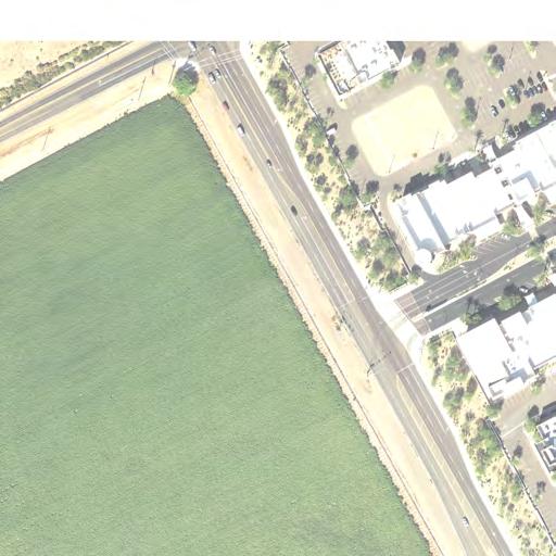
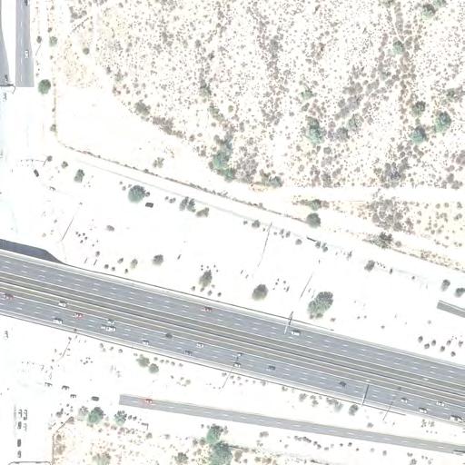
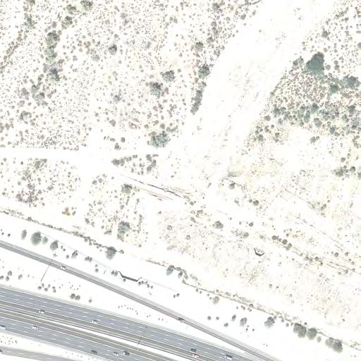
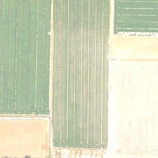
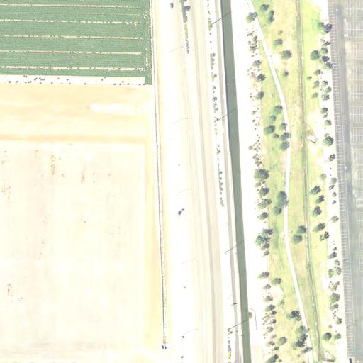
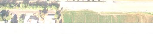
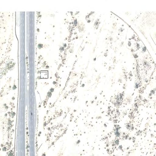
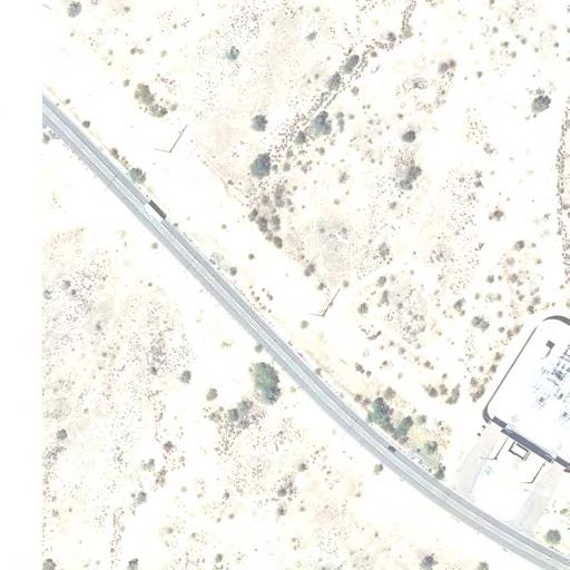
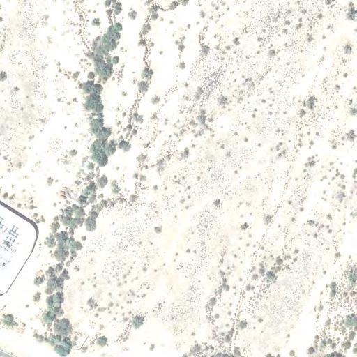
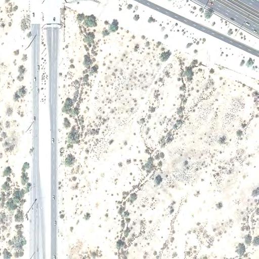
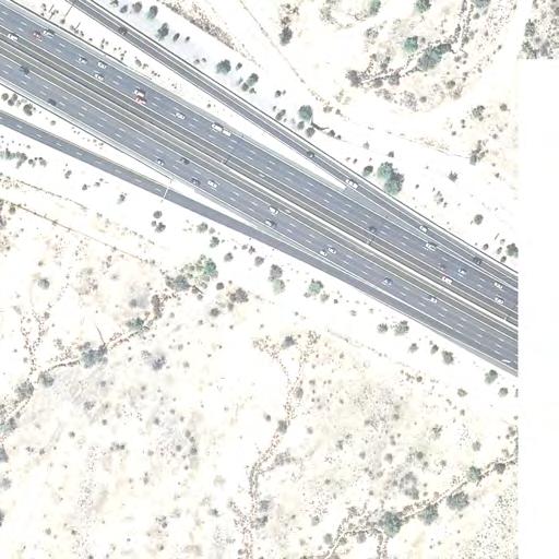
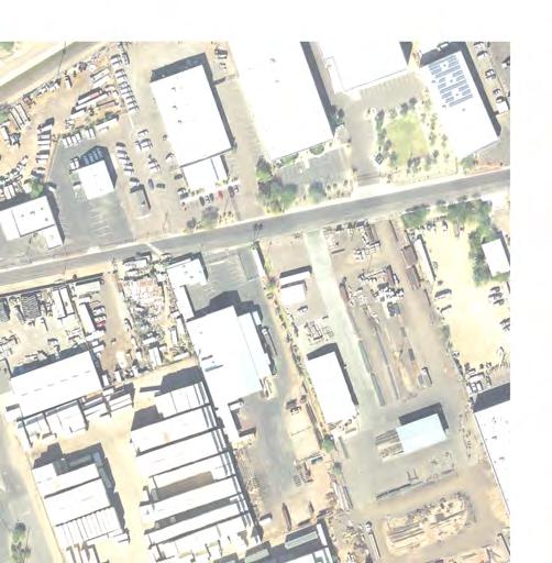
15 Interstate 10 Papago Freeway I-10/Papago Freeway: Loop 101/Aqua Fria Freeway to N. 59th Avenue 4.9 Miles +/- The freeway mainline is depressed throughout this segment and consists of four general purpose (GP) lanes in each direction with east- and westbound high-occupancy vehicle (HOV) lanes adjacent to the median. Auxiliary lanes to facilitate entering and exiting the GP lanes are provided between N. 67 th and N. 83 rd avenues in the westbound direction and between N. 83 rd and N. 75 th avenues in the eastbound direction. Also, a GP lane has been added between N. 83 rd and N. 75 th avenues in the eastbound direction. Tight urban diamond interchanges (TUDIs) have been constructed at one-mile intervals N. 91 st Avenue, N. 83 rd Avenue, N. 75 th Avenue, and N. 67 th Avenue. The ramp terminal intersections are generally spaced approximately 500 feet at all interchanges. Direct HOV ramps to/from the east have been constructed at N. 79th Avenue with access to W. McDowell Road to the north. The bridge structure is constructed to accommodate access to W. Van Buren Street the south, but this connection has yet to be completed. A second overcrossing exists at N. 63rd Avenue, but connections to the north and south have not been completed. A substantial storm drain (approximately 90 feet across at the top) parallels Interstate 10 through the entire length of this segment, undercrossing each of the three arterials directly north ( feet) of the westbound on-ramp/off-ramp terminal. Residential developments, particularly high-density apartment complexes, predominantly line the north side of I-10. Land uses along the south side are mostly commercial and light industrial. There are large undeveloped parcels north and south of Interstate 10 through this segment. Continuation of the local roadway network south of I-10 is obstructed by the Union Pacific Railroad (UPRR) mainline track of its Phoenix Subdivision. In addition, the Roosevelt Irrigation Canal, a feature of some historic significance, has a southwest-by-southeast zigzag path from west of N. 83 rd Avenue to W. Buckeye Road at S. 67 th Avenue. The Phoenix West extension of METRO Light Rail, the regional light rail transit (LRT) line, is proposed to be constructed in the median of I-10 to N. 79 th Avenue. Potential Diverging Diamond Interchanges The TUDIs at N. 83 rd Avenue, N. 75 th Avenue, and N. 67 th Avenue potentially could be converted to DDIs should operational and capacity improvements be required in the future (Exhibit 1). Average annual daily traffic (AADT) forecasts prepared by ADOT for the segment indicate volumes exceeding 340,000 vehicles per day east of N. 75 th Avenue in the year Exhibit 2 shows the three interchange areas at a larger scale for easier reference. EXHIBIT 1 POTENTIAL DDI LOCATIONS ON I 10/PAPAGO FREEWAY WEST SEGMENT N. 83 rd Ave 27,100 N. 75 th Ave 24,500 W. McDowell Rd N. 67 th Ave 18,700 48, ,000 (2010) 266,000 (2030) DHOV Lanes 24, ,000 (2010) 348,000 (2030) S t o r m D r a i n 24, ,000 (2010) 364,000 (2030) Image Source: Bing Maps XXXX = ADOT State Highway System Average Annual Daily Traffic AADT (Year) XXXX = MAG 8 Million scenario SED on 2031 Network Model Run 24 Hour Volumes 0 1,000 2,000 Approx. Scale in Feet TECHNICAL MEMORANDUM Page A-1 of 14


16 EXHIBIT 2 POTENTIAL DDI LOCATIONS AT N. 83 RD, N. 75 TH, AND N. 67 TH AVENUES ON I 10/PAPAGO FREEWAY WEST SEGMENT Storm Drain Pump House Storm Drain Pump House HOV Lane HOV Lane N. 83 rd Ave N. 75 th Ave HOV Lane HOV Lane Storm Drain HOV Lane HOV Lane Pump House N. 67 th Ave NOTE: Blue lines identify development or subdivision boundaries, as platted. Orange lines identify privately owned parcels. Land outside the orange lines is dedicated roadway right of way or publicly owned. Image Source: Maricopa County Assessor Interactive Maps Approx. Scale in Feet I-10/Papago Freeway: N. 59th Avenue to The Stack at I-17/Black Canyon Freeway 4.5 Miles +/- The freeway mainline is depressed throughout this segment and consists of four GP lanes in each direction with east- and westbound HOV lanes adjacent to the median from N. 59 th Avenue to N. 35 th Avenue. Auxiliary lanes to facilitate entering and exiting the GP lanes are provided between each of the arterial interchanges. Between N. 35 th and N. 27 th avenues, the freeway remains depressed and consists of five GP lanes in both directions with east- and westbound HOV lanes. The freeway becomes elevated as it approaches N. 27 th Avenue. East of N. 27 th Avenue to the I-17/Black Canyon Freeway system interchange, Interstate 10 consists of three GP lanes in each direction with east- and westbound HOV lanes occupying the innermost portion of the roadway. TUDIs have been constructed at each of the four of the mile-road arterials crossing over Interstate 10 N. 59 th Avenue, N. 51 st Avenue, N. 43 rd Avenue, and N. 35 th Avenue. The interchange at N. 27 th Avenue is constructed as a half-diamond - west only. Spacing between the ramp terminal intersections varies between 425 feet and 500 feet. Additional overcrossings are provided at N. 31 st Avenue and N. 39 th Avenue with connections to W. McDowell Road to the north and W. Van Buren Street to the south. The substantial storm drain of the previous segment continues parallel with Interstate 10 between N. 59 th and N. 43 rd avenues, undercrossing N. 59 th and N. 51 st avenues directly north ( feet) of the westbound on-ramp/off-ramp terminal. Land uses along the corridor are a mixture of residential developments and commercial/industrial properties. There are several large agricultural parcels south of Interstate 10 between N. 59th and N. 51st avenues. Development of the local north-south arterial roadway network to the south of I-10 is constrained by the UPRR TECHNICAL MEMORANDUM Page A-2 of 14
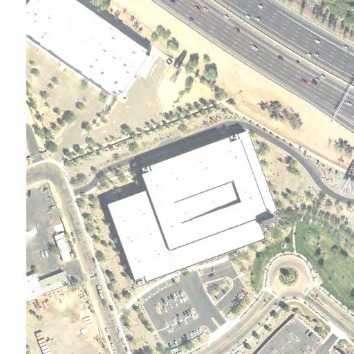
17 mainline track and to the north by the Grand Canal. Only the mile-roads have been constructed south of the UPRR track, and all crossings are at-grade. The Grand Canal has restricted travel to the mile-roads and two ½-mile roads (N. 55th and N. 47th avenues). Ongoing regional planning activities include consideration of a connection of the Loop 202/South Mountain Freeway at Interstate 10, potentially in the area of N. 59th Avenue. Also, the Phoenix West extension of METRO Light Rail is proposed to be constructed in the median of Interstate 10 to from downtown Phoenix to N. 79th Avenue. Potential Diverging Diamond Interchanges The TUDIs at N. 59th Avenue, N. 51st Avenue, and N. 43rd Avenue potentially could be converted to DDIs should operational and capacity improvements be required in the future (Exhibit 3). Average annual daily traffic (AADT) forecasts prepared by ADOT for the segment indicate volumes exceeding 370,000 vehicles per day east of N. 59 th Avenue in the year Exhibit 4 shows the three interchange areas at a larger scale for easier reference. EXHIBIT 3 POTENTIAL DDI LOCATIONS ON I 10/PAPAGO FREEWAY EAST SEGMENT N. 59 th Ave 24,400 Note: Potential connection with S. Mtn Fwy W. McDowell Rd S t o r m D r a i n 230,000 (2010) 376,000 (2030) N. 51 st Ave 20,100 23, ,000 (2010) 388,000 (2030) N. 43 rd Ave 20,900 31, ,000 (2010) 381,000 (2030) Image Source: Bing Maps XXXX = ADOT State Highway System Average Annual Daily Traffic AADT (Year) XXXX = MAG 8 Million scenario SED on 2031 Network Model Run 24 Hour Volumes 0 1,000 2,000 Approx. Scale in Feet I-10 Maricopa Freeway I-10/Maricopa Freeway: The Split at I-17/Black Canyon Freeway to SR-143/Hohokam Expressway 3.6 Miles +/- In this section of the I-10 corridor, interchanges are provided at three locations: S. 24 th Street (half-diamond - east only), E. University Drive/S. 32 nd Street (TUDI), and S. 40 th Street (diamond with a Part-Clover Leaf (Par-Clo) in the southeast quadrant. The freeway mainline is at-grade throughout this segment and consists of six GP lanes in the westbound direction east of the E. University Drive/S. 32 nd Street traffic interchange to the S. 24 th Street with an HOV lanes adjacent to the median. At this point, three lanes split to the right, cross over the other three lanes and continue west to become Interstate 17/Black Canyon Freeway. The three other lanes split to the left, cross under the other three lanes and continue north as Interstate 10; the HOV lane remains with these three lanes. In the eastbound direction, there are five GP lanes and an HOV lane adjacent the median. TECHNICAL MEMORANDUM Page A-3 of 14


.")
18 EXHIBIT 4 POTENTIAL DDI LOCATIONS AT N. 59 TH, N. 51 ST, AND N. 43 RD AVENUES ON I 10/PAPAGO FREEWAY EAST SEGMENT Storm Drain Storm Drain Pump House Pump House HOV Lane HOV Lane N. 59 th Ave HOV Lane HOV Lane N. 51 st Ave Noise Wall Storm Drain HOV Lane HOV Lane N. 43 rd Ave Pump Station Noise Wall NOTE: Blue lines identify development or subdivision boundaries, as platted. Orange lines identify privately owned parcels. Land outside the orange lines is dedicated roadway right of way or publicly owned. Noise Wall Image Source: Maricopa County Assessor Interactive Maps Approx. Scale in Feet A transition is made at the E. University Drive/S. 32 nd Street traffic interchange to five GP lanes westbound and four lanes eastbound with HOV lanes in the center. West of S. 40 th Street, there are four GP lanes in each direction with the HOV lanes. Auxiliary lanes are added in both directions between S. 40 th Street and S. 48 th Street/Hohokam Expressway (SR-143). The distance between the S. 24 th Street and E. University Drive/S. 32 nd Street interchanges is approximately 1.5 miles. Within this section, Interstate 10 crosses the Salt River. The distance from the E. University Drive/S. 32 nd Street traffic interchange to the Hohokam Expressway traffic interchange is 1.9 miles. There are no additional corridor crossings. The Tempe Drain flows under E. University Drive directly north (approximately 120 feet) of the westbound on-ramp/off-ramp terminal. Commercial, industrial, and institutional land uses line Interstate 10 through this segment. The local north-south arterial roadway network is disrupted by Sky Harbor International Airport (Sky Harbor) and the Salt River. S. 24 th Street provides access to the western end of Sky Harbor, including the old tower area and the Arizona Air National Guard, extensive rental car facilities, and the Greyhound Bus Depot on the southwest corner at E. Buckeye Road. Potential Diverging Diamond Interchanges The E. University Drive/S. 32 nd Street diamond interchange could be converted to a DDI (Exhibit 5). Average annual daily traffic (AADT) forecasts prepared by ADOT for TECHNICAL MEMORANDUM Page A-4 of 14
 427,000 (2030) S. 32 nd St E. Wood St Image Source: Google Earth 0 500 1,000 Approx.")


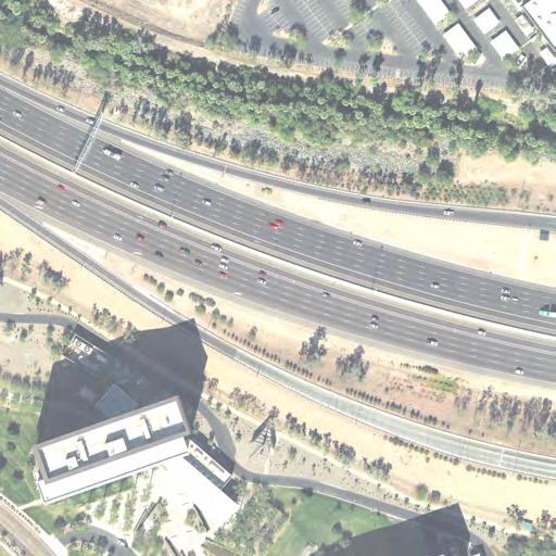
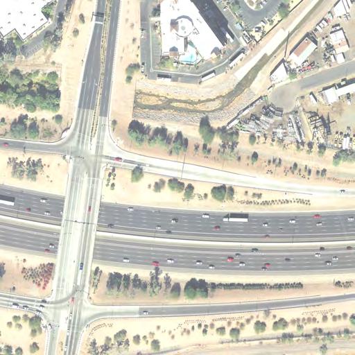
19 EXHIBIT 5 POTENTIAL DDI LOCATION AT E. UNIVERSITY DRIVE/S. 32 ND STREET OVER I 10/MARICOPA FREEWAY E. Elwood St E. University Dr 22,400 Tempe Drain HOV Lanes E. University Dr Tempe Drain 25, ,000 (2010) 427,000 (2030) S. 32 nd St E. Wood St Image Source: Google Earth ,000 Approx. Scale in Feet XXXX = ADOT State Highway System Average Annual Daily Traffic AADT (Year) XXXX = MAG 8 Million scenario SED on 2031 Network Model Run 24 Hour Volumes S. 32 nd St NOTE: Blue lines identify development or subdivision boundaries, as platted. Orange lines identify privately owned parcels. Land outside the orange lines is dedicated roadway right of way or publicly owned. Image Source: Maricopa County Assessor Interactive Maps Approx. Scale in Feet 500 the segment indicate volumes exceeding 310,000 vehicles per day east of N. 59 th Avenue in the year Exhibit 5 also shows the interchange area at a larger scale for easier reference. I-10/Maricopa Freeway: US-60/Superstition Freeway to Pecos Stack at Loop 202/Santan Freeway 6.3 Miles +/- TUDIs provide access to the major mile arterials Baseline Road, Elliot Road, Warner Road, Ray Road, and Chandler Boulevard. With the exception of Baseline Road, a TUDI, major arterials pass over the freeway mainline. An overcrossing is provided at W. Guadalupe Road. The freeway mainline is at-grade through the US-60/Supersittion Freeway system interchange, becoming elevated over W. Baseline Road. The freeway then takes on a cross-section that is slightly depressed relative to the west side and slightly elevated relative to the east side. The freeway is semi-depressed under all of the mile-road arterials, resulting in inclined ramps serving semi-elevated arterial ramp terminals. This segment of Intertate 10 has three GP lanes in each direction with eastand westbound HOV lanes adjacent to the median through its length. Auxiliary lanes to facilitate entering and exiting the GP lanes and support queuing of ramp traffic are provided between all interchanges from the US-60/Supersittion Freeway system interchange to the Pecos Stack. A mix of residential and commercial developments lines this segment of Interstate 10. Two large commercial developments are located on the east side of the freeway: Arizona Mills Outlet Mall in the southeast quadrant of Interstate 10 and US-60 and Tempe Autoplex in the southeast quadrant of Interstate 10 and Elliot Road. Between Warner Road and Ray Road, Mountain Vista Park is located along the west side, and a large drainage retention basin is on the east side. The Highline Canal South Lateral, which is south of Baseline Road west of the freeway forms a south-by-southwest loop east of the freeway, which impacts the local roadway network. This canal is an underground culvert between W. Orchid Lane (east of the freeway) and E. Thistle Landing Drive (west of the freeway), passing directly through the I-10/Ray Road traffic interchange. TECHNICAL MEMORANDUM Page A-5 of 14


20 Potential Diverging Diamond Interchanges The TUDIs at Elliot Road, Warner Road, Ray Road, and Chandler Boulevard could be converted to DDIs (Exhibit 6). However, the steep grades approaching the ramp terminal intersections are a potential design issue. Average annual daily traffic (AADT) forecasts prepared by ADOT for the segment indicate volumes exceeding 350,000 vehicles per day at W/E Elliot Road in the year Forecast 2030 traffic volumes at the south end of this segment, approaching W/E Chandler Boulevard, are close to 180,000 AADT. Exhibit 7 shows the interchange area at a larger scale for easier reference. EXHIBIT 6 POTENTIAL DDI LOCATIONS ON I 10/MARICOPA FREEWAY US 60 TO THE PECOS STACK TEMPE E. Elliot Rd 12, ,000 (2010) 350,000 (2030) 19,500 W. Elliot Rd Highline Canal 155,000 (2010) 253,000 (2030) TEMPE AUTOPLEX E. Ray Rd 28,200 29,600 W. Ray Rd PHOENIX TEMPE PHOENIX CHANDLER E. Warner Rd S. 48 th Street 166,000 (2010) 292,000 (2030) 7,000 20,700 W. Warner Rd Highline Canal S. Priest Drive S. 48 th Street E. Chandler Blvd 23, ,000 (2010) 178,000 (2030) 33,800 S. Priest Drive W. Chandler Blvd Image Source: Bing Maps XXXX = ADOT State Highway System Average Annual Daily Traffic AADT (Year) XXXX = MAG 8 Million scenario SED on 2031 Network Model Run 24 Hour Volumes Pecos Stack 0 1,000 2,000 Approx. Scale in Feet TECHNICAL MEMORANDUM Page A-6 of 14


21 EXHIBIT 7 POTENTIAL DDI LOCATIONS AT ELLIOT ROAD, WARNER ROAD, RAY ROAD, AND CHANDELER BOULEVARD ON I 10/MARICOPA FREEWAY US 60 TO THE PECOS STACK HOV Lanes Elliot Rd HOV Lanes Warner Rd Pump House HOV Lanes Ray Rd HOV Lanes Chandler Blvd Approx. Scale in Feet NOTE: Blue lines identify development or subdivision boundaries, as platted. Orange lines identify privately owned parcels. Land outside the orange lines is dedicated roadway right of way or publicly owned. Image Source: Maricopa County Assessor Interactive Maps TECHNICAL MEMORANDUM Page A-7 of 14
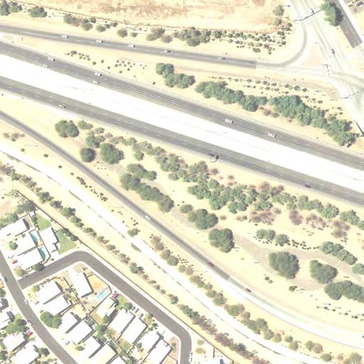
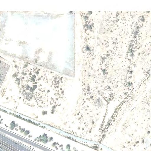
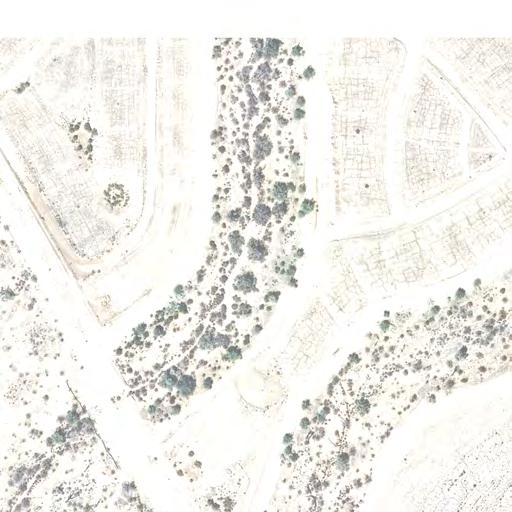
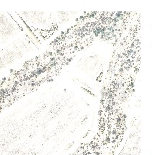
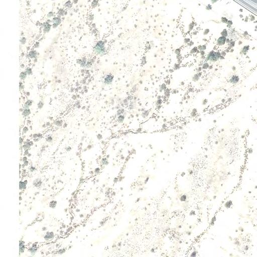
22 Loop 101 Agua Fria Freeway Loop 101/Aqua Fria Freeway: I-10/Papago Freeway to W. Peoria Avenue 8.2 Miles +/- Different treatments of TUDIs are provided at the mile-road arterials through this segment of Loop 101/Agua Fria Freeway W. Mc Dowell Road (half - diamond - north only), W. Thomas Road (TUDI), W. Indian School Road (TUDI), W. Camelback Road (SPUI), W. Bethany Home Road (TUDI), W. Glendale Avenue (SPUI), W. Northern Avenue (Spread), and W. Olive Avenue (TUDI). There is an additional corridor crossing at W. Maryland Avenue (over), located mid-way between W. Glendale Avenue and W. Bethany Home Road. W. Maryland Avenue provides direct access to University of Phoenix Stadium, Jobing.com Arena, and Westgate City Center, a mixed-use development with interactive shopping, dining, and entertainment. ADOT recently released a bid request for construction of DHOV ramps in conjunction with the W. Maryland Avenue overpass. The freeway has three GP lanes in each direction through the entire length of this segment. A northbound HOV lane begins immediately north of the Interstate 10 system interchange and continues through the entire length of the segment. A southbound HOV lane is present from W. Peoria Avenue to directly north of W. Thomas Road. Auxiliary lanes are present between each of the traffic interchanges to facilitate entering and exiting the GP lanes and support queuing of ramp traffic. The freeway generally is at-grade between traffic interchanges and elevated over crossing arterials. The lone exception to this is W. Indian School Road, which crosses over the depressed freeway. The northern two miles of this freeway corridor, between W. Northern Avenue and W. Peoria Avenue, are nearly built out with residential and commercial developments. A good portion of the central and southern segments still is used for agricultural purposes, although residential, entertainment, and commercial developments are present. Westgate City Center, University of Phoenix Stadium, and Jobing.com Arena are located along the east side of the corridor between W. Glendale Avenue and W. Bethany Home Road. Because portions of the corridor are undeveloped, the potential exists to preserve/acquire ROW for future transportation improvements and to incorporate those future improvements into development plans. Potential Diverging Diamond Interchanges Due to skewed crossing and wide spacing of ramp terminal intersections, the W. Northern Avenue traffic interchange offers good potential to convert to a DDI, should additional operational/capacity improvements be needed at this location (Exhibit 8). Skewed interchange designs and widely spaced terminal ramps often result in the SPUI being a cost prohibitive solution. Therefore, a DDI would have a distinct advantage at this location. Three TUDIs W. Thomas Road, W. Indian School Road, and W. Bethany Home Road also offer opportunities for conversion to a DDI should additional/capacity improvements be needed in the future (Exhibit 9). Preliminary analysis indicates additional ROW likely would be needed at the three TUDIs to increase the distance between ramp intersections, as there is less than 500 feet between ramp terminals. An additional issue associated with these three locations is the presence of major storm drainage facilities and, in the case of W. Bethany Home Road, a canal parallels the interchange on the north side. Exhibit 10 shows the three interchange areas at a larger scale for easier reference. Average annual daily traffic (AADT) forecasts prepared by ADOT for the segment indicate volumes approaching 250,000 vehicles per day north of W. Indian School Road in the year Recorded 2010 traffic volumes at the south end of this segment are in the neighborhood of 130,000 AADT. Loop 101/Aqua Fria Freeway: W. Peoria Avenue to N. 75th Avenue 6.5 Miles +/- Along this segment of Agua Fria Freeway, a mixture of diamond-type interchanges provides access to the major mile-road arterials W. Peoria Avenue (TUDI), US-60/W. Grand Avenue (half-diamond south only), W. Thunderbird Road (Spread), W. Bell Road (SPUI), W. Union Hills Drive (TUDI), N. 91 st Avenue (slip ramps north only). The interchanges are spaced at approximately one-mile intervals with the exception of the spacing between W. Bell Road and W. Thunderbird Road, which is two miles, because W. Greenway Road has not been continued as a major arterial west of N. 67 th Avenue. TECHNICAL MEMORANDUM Page A-8 of 14
 193,000 (2030) 49,400 W. Northern Ave W.")


 249,000 (2030) Storm Drain S t o r m D r a i n 30,000 25,500 W. Thomas Rd W. Indian School Rd 29,300 Canal W.")
23 EXHIBIT 8 POTENTIAL DDI AT W. NORTHERN AVENUE ON LOOP 101/AGUA FRIA FREEWAY HOV Lanes N. 99 th Ave 44, ,000 (2010) 193,000 (2030) 49,400 W. Northern Ave W. Northern Ave Image Source: Bing Maps 0 1,000 2,000 Approx. Scale in Feet Image Source: Maricopa County Assessor Interactive Maps XXXX = ADOT State Highway System Average Annual Daily Traffic AADT (Year) XXXX = MAG 8 Million scenario SED on 2031 Network Model Run 24 Hour Volumes Approx. Scale in Feet NOTE: Blue lines identify development or subdivision boundaries, as platted. Orange lines identify privately owned parcels. Land outside the orange lines is dedicated roadway right of way or publicly owned. EXHIBIT 9 POTENTIAL DDI LOCATIONS ON LOOP 101/AGUA FRIA FREEWAY 17, ,000 (2010) 232,000 (2030) Storm Drain 130,000 (2010) 249,000 (2030) Storm Drain S t o r m D r a i n 30,000 25,500 W. Thomas Rd W. Indian School Rd 29,300 Canal W. Bethany Home Rd 24, ,000 (2010) 238,000 (2030) Image Sources: Bing Maps XXXX = ADOT State Highway System Average Annual Daily Traffic AADT (Year) XXXX = MAG 8 Million scenario SED on 2031 Network Model Run 24 Hour Volumes 0 1,000 2,000 Approx. Scale in Feet TECHNICAL MEMORANDUM Page A-9 of 14


24 EXHIBIT 10 POTENTIAL DDI LOCATIONS AT W. THOMAS RD, W. INDIAN SCHOOL RD, AND W. BETHANY HOME RD LOOP 101/AGUA FRIA FREEWAY S t o r m D r a i n Approx. Scale in Feet C a n a l HOV Lanes W. Bethany Home Rd HOV Lanes W. Indian School Rd S t o r m D r a i n Pump House W. Thomas Rd HOV Lanes S t o r m D r a i n NOTE: Blue lines identify development or subdivision boundaries, as platted. Orange lines identify privately owned parcels. Land outside the orange lines is dedicated roadway right of way or publicly owned. Image Source: Maricopa County Assessor Interactive Maps TECHNICAL MEMORANDUM Page A-10 of 14


25 The freeway continues north from W. Peoria Avenue with three GP lanes in each direction and HOV lanes adjacent the median. Auxiliary lanes are provided at the following locations: between W. Peoria Avenue and US-60/Grand Avenue, connecting the N. 91 st Avenue northbound on-ramp with W. Thunderbird Road, between W. Bell Road and W. Union Hills Drive, and between W. Union Hills Drive and N. 75 th Avenue (northbound only). The mainline alignment follows New River and crosses Skunk Creek approximately one-half south of W. Bell Road, constraining the location and design of the interchanges. An additional corridor crossing is provided at N. 83 rd Avenue. A new collector-distributor ramp recently was constructed between N. 75 th Avenue and W. Union Hills Drive with a Texas U-turn at W. Union Hills Drive. Completion of this project provides a direct connection of W. Beardsley Road across New River to Loop 101 and improves access to Loop 101 for W. Lake Pleasant Parkway/N. 83 rd Avenue. Land uses at the northern and southern ends of this segment of the freeway predominately are residential. Significant commercial development is located in the central portion of the segment, including: Arrowhead Towne Center, north of W. Bell Road; and the Peoria Sports Complex/Entertainment District and North Valley Power Center, situated south of W. Bell Road. All interchanges provide access to the Sun City developments located just to the west of the freeway. The continuity of the adjacent roadway network is significantly affected by New River, Skunk Creek, Arizona Canal, Arizona Canal Diversion Channel, and the Burlington Northern Santa Fe (BNSF) Railway mainline. Potential Diverging Diamond Interchanges In this freeway segment, there is only the potential to convert the W. Thunderbird Road traffic interchange to a DDI, should additional operational/capacity improvements be needed at this location (Exhibit 11). The skewed crossing and more than adequate spacing of the ramp terminal intersections, as is the case at W. Northern Avenue, gives this location good potential for increasing capacity with a DDI, as the SPUI cannot be considered a viable alternative. There may be a need to modify the culvert accommodating drainage along the east side of the freeway. EXHIBIT 11 POTENTIAL DDI LOCATION AT W. THUNDERBIRD RD ON LOOP 101/AGUA FRIA FREEWAY HOV Lanes 42,600 42,400 W. Thunderbird Rd W. Thunderbird Rd 107,000 (2010) 199,000 (2030) Storm Drain Image Source: Bing Maps 0 1,000 2,000 Storm Drain Approx. Scale in Feet XXXX = ADOT State Highway System Average Annual Daily Traffic AADT (Year) XXXX = MAG 8 Million scenario SED on 2031 Network Model Run 24 Hour Volumes Image Source: Maricopa County Assessor Interactive Maps Approx. Scale in Feet NOTE: Blue lines identify development or subdivision boundaries, as platted. Orange lines identify privately owned parcels. Land outside the orange lines is dedicated roadway right of way or publicly owned. TECHNICAL MEMORANDUM Page A-11 of 14
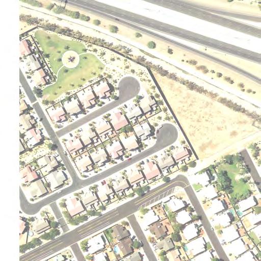
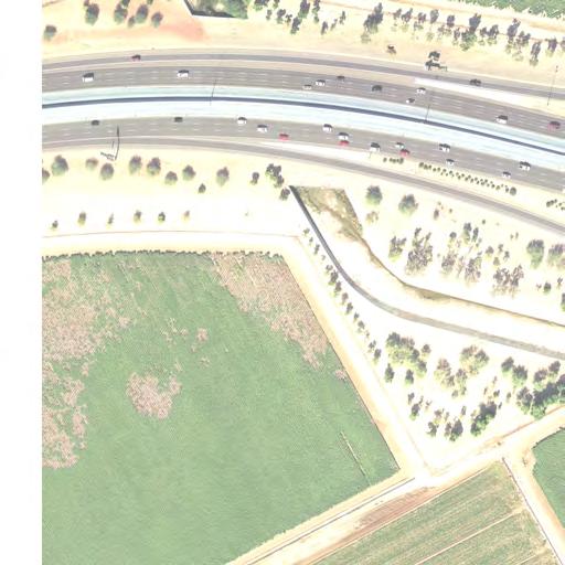
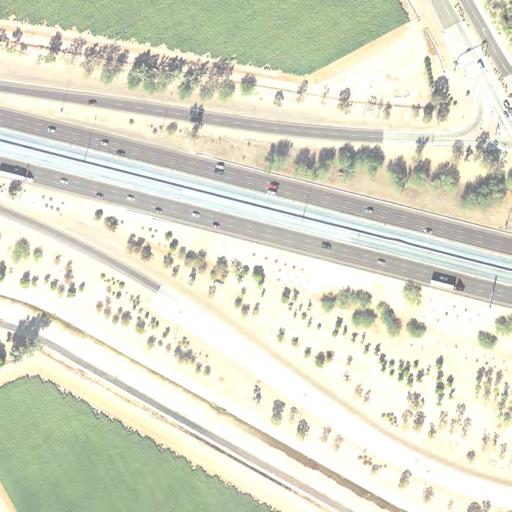
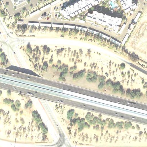
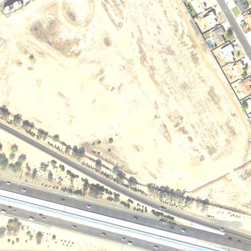
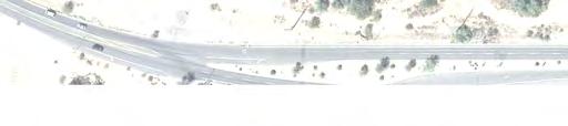
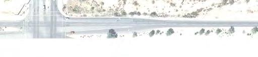
26 Loop 101 Pima Freeway Loop 101/Pima Freeway: SR-51/Piestewa Freeway to East Princess Drive/North Pima Road 6.4 Miles +/- This segment of Loop 101 passes through one of the most rapidly developing areas of northern Phoenix/Scottsdale. A SPUI has been constructed at N. Tatum Boulevard. TUDIs are provided at the mile-road arterials N. 56 th Street, N. 64 th Street, N. Scottsdale Road, and N. Hayden Road. The freeway mainline generally consists of three GP lanes in each direction with HOV lanes adjacent the median. In the transition region from SR-51/Piestewa Freeway to N. Tatum Boulevard, there is an additional eastbound GP lane and auxiliary lanes in both directions. There also are auxiliary lanes between N. Tatum Boulevard and N.56 th Street (both eastbound and westbound), between N. 56 th and N. 64 th streets (westbound only), between N. 64 th Street and N. Scottsdale Road (eastbound only), between N. Scottsdale Road and N. Hayden Road (both eastbound and westbound), and between N. Hayden and E. Princess Drive/N. Pima Road (both eastbound and westbound). Generally, the Loop 101/Pima Freeway is an at-grade facility on crossing east-to-west on a large alluvial fan; therefore, land is slightly higher on the north side. As a result, extensive drainage improvements have been installed along the north side of freeway through this segment. The freeway is elevated over all arterials except N. 64 th Street, which crosses over the freeway. There are no roadways connecting to the N. 64th Street overpass at this time. On the north side of the freeway, between N. Scottsdale Road and N. Hayden Road, a one-way frontage road recently was constructed, and N. Hayden Road only recently was completed between E. Princess Drive and E. Thompson Peak Parkway. At the present time, there are no additional crossings of the freeway. Significant regional commercial developments and recreational attractions are located within and accessed along this segment of Loop 101, including: CAP Reach 11 Sports Complex, which extends from west of SR-51 to Scottsdale Road; Desert Ridge Marketplace (northeast quadrant of Loop 101 and N. Tatum Boulevard); Marriott Wildfire Golf Club and Resort, accessible from N. Tatum Boulevard and N. 56 th Street; Mayo Clinic Hospital and Musical Instrument Museum (MIM), one-half mile south of Loop 101 on N. Tatum Boulevard; Scottsdale 101 and adjoining Chauncey Lane commercial/entertainment complex (southeast quadrant of Loop 101 and N. Scottsdale Road); Henkel (Dial) Headquarters (northeast quadrant of Loop 101 and N. Scottsdale Road); and Tournament Players Club (TPC), one mile south of Loop 101 between N. Hayden Road and N. Scottsdale Road;). However, most of that land in this freeway segment remains undeveloped; therefore, this is an excellent time to plan and secure ROW for future transportation improvements. These improvements could be incorporated as future commercial and residential development is implemented. Potential Diverging Diamond Interchanges The TUDIs at N. 56th Street and N. Hayden Road have good ramp intersection spacing and potentially could be converted to DDIs should operational and capacity improvements be required in the future (Exhibit 12). Average annual daily traffic (AADT) forecasts prepared by ADOT for the segment indicate volumes exceeding 250,000 vehicles per day on this segment of the freeway in the year Exhibit 13 shows the two interchange areas at a larger scale for easier reference. TECHNICAL MEMORANDUM Page A-12 of 14
 254,000 (2030) N. 56 th ST N.")
 XXXX = MAG 8 Million scenario SED")
27 EXHIBIT 12 POTENTIAL DDI LOCATIONS ON LOOP 101/PIMA FREEWAY 140,000 (2010) 258,000 (2030) 66,000 Storm Drainage System 48,500 Storm Drainage System 30, ,000 (2010) 254,000 (2030) N. 56 th ST N. Hayden Rd Image Source: Google Earth E. Mayo Blvd XXXX = ADOT State Highway System Average Annual Daily Traffic AADT (Year) XXXX = MAG 8 Million scenario SED on 2031 Network Model Run 24 Hour Volumes 0 1,000 2,000 Approx. Scale in Feet TECHNICAL MEMORANDUM Page A-13 of 14


28 EXHIBIT 13 POTENTIAL DDI LOCATIONS AT N. 56 TH STREET AND N. TATUM ROAD ON LOOP 101/PIMA FREEWAY Storm Drainage System Storm Drainage System N. 56 th ST Storm Drain N. Hayden Rd Storm Drain Image Source: Maricopa County Assessor Interactive Maps NOTE: Blue lines identify development or subdivision boundaries, as platted. Orange lines identify privately owned parcels. Land outside the orange lines is dedicated roadway right of way or publicly owned Approx. Scale in Feet TECHNICAL MEMORANDUM Page A-14 of 14
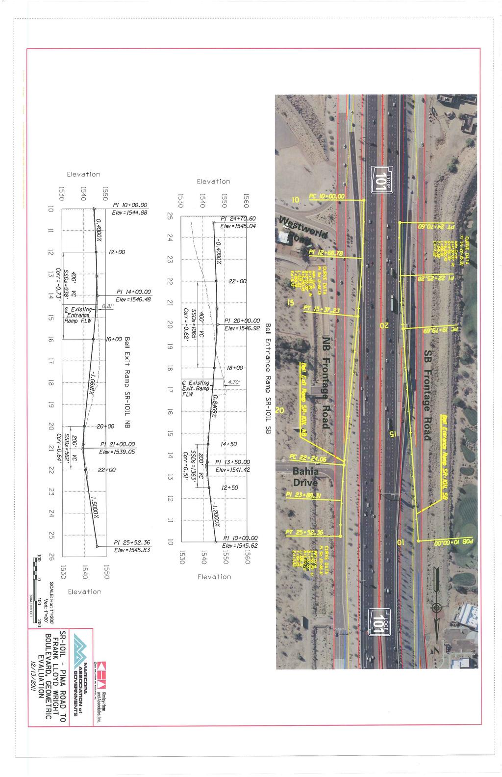
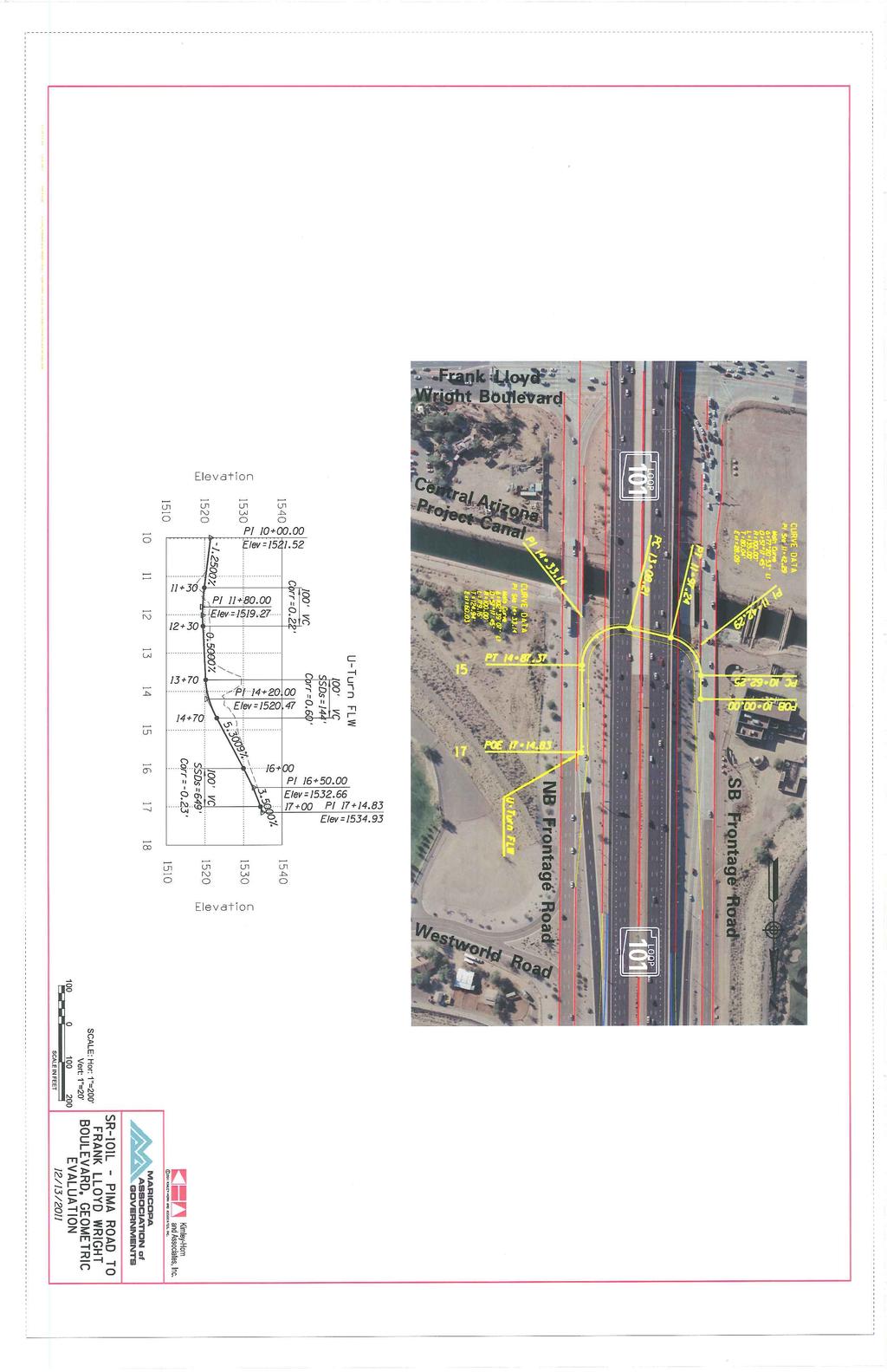
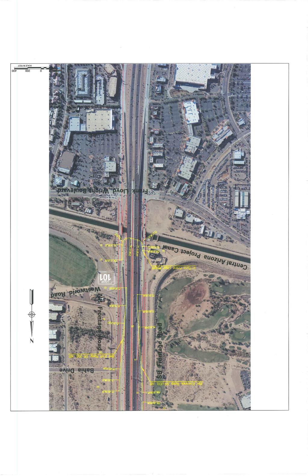
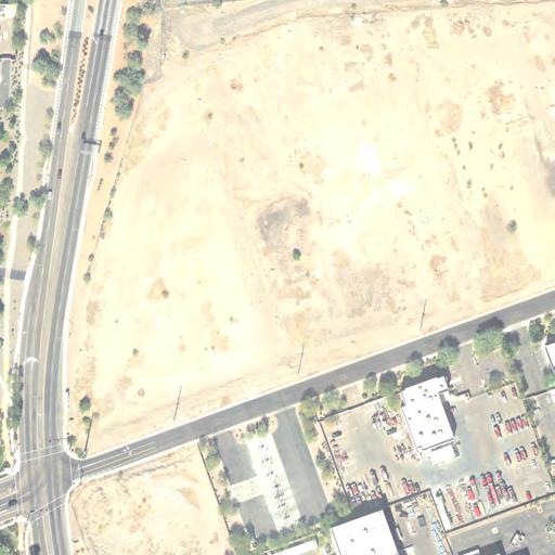
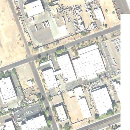
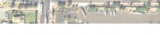
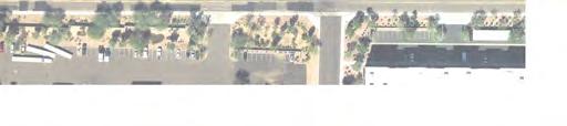
29 Attachment B Preliminary Engineering Plan Drawing for Potential E. Princess Dr/N. Pima Rd DDI Conversion TECHNICAL MEMORANDUM
30
31
32
33
34
35
36
37
38
39 Attachment C Preliminary Conceptual Engineering Drawings: Conversion of Selected Urban Diamond Interchanges to Diverging Diamond Interchanges TECHNICAL MEMORANDUM
40 Thunderbird Rd SR101L CONCEPTUAL DESIGN FOR DISCUSSION PURPOSES ONLY SCALE (FEET) DDI Concept SR-101L & THUNDERBIRD RD SHEET 1 OF 1


41 Thom as Road SR101L CONCEPTUAL DESIGN FOR DISCUSSION PURPOSES ONLY SCALE (FEET) DDI Concept SR-101L & THOMAS RD SHEET 1 OF 1


42 N orthern Ave SR101L CONCEPTUAL DESIGN FOR DISCUSSION PURPOSES ONLY SCALE (FEET) DDI Concept SR-101L & NORTHERN AVE SHEET 1 OF 1


43 Hayden Rd SR101L CONCEPTUAL DESIGN FOR DISCUSSION PURPOSES ONLY SCALE (FEET) DDI Concept SR-101L & HAYDEN RD SHEET 1 OF 1


44 99th Avenue SR101L Bethany Hom e Rd CONCEPTUAL DESIGN FOR DISCUSSION PURPOSES ONLY SCALE (FEET) DDI Concept SR-101L & BETHANY HOME RD SHEET 1 OF 1


45 SR101L 56th Street CONCEPTUAL DESIGN FOR DISCUSSION PURPOSES ONLY SCALE (FEET) DDI Concept SR-101L & 56TH ST SHEET 1 OF 1


46 Elwood Street U niveristy Drive I-10 32nd Street CONCEPTUAL DESIGN FOR DISCUSSION PURPOSES ONLY SCALE (FEET) DDI Concept I-10 & UNIVERSITY DR/32ND ST SHEET 1 OF 1


47 McDowell Road I-10 75th Avenue CONCEPTUAL DESIGN FOR DISCUSSION PURPOSES ONLY SCALE (FEET) DDI Concept I-10 & 75TH AVE SHEET 1 OF 1