DIVERGING DIAMOND INTERCHANGE. Informational Guide
|
|
|
- Giles Porter
- 5 years ago
- Views:
Transcription


1 DIVERGING DIAMOND INTERCHANGE Informational Guide August 2014
2 FOREWORD The Federal Highway Administration (FHWA) Every Day Counts (EDC) initiative is designed to identify and deploy innovation aimed at reducing project delivery time, enhancing safety and protecting the environment. In 2012, FHWA chose Intersection & Interchange Geometrics (IIG) to feature as one of the innovative technologies in EDC-2. Specifically, IIG consists of a family of alternative intersection designs that improve intersection safety while also reducing delay, and at lower cost and with fewer impacts than comparable traditional solutions. As part of the effort to mainstream these intersections, FHWA has produced a series of guides to help transportation professionals routinely consider and implement these designs. Concurrent with this Diverging Diamond Interchange (DDI) Informational Guide, FHWA developed and published guides for three other designs: Median U-turn (MUT), Displaced Left Turn (DLT), and Restricted Crossing U-turn (RCUT). These guides represent summaries of the current state of knowledge and practice, and are intended to inform project planning, scoping, design and implementation decisions. An electronic version of this document is available on the Office of Safety website at Additionally, limited quantities of hard copies are available from the Report Center; inquiries may be directed to report.center@dot.gov or Michael S. Griffith Director Office of Safety Technologies Notice This document is disseminated under the sponsorship of the U.S. Department of Transportation in the interest of information exchange. The U.S. Government assumes no liability for the use of the information contained in this document. This report does not constitute a standard, specification, or regulation. The U.S. Government does not endorse products or manufacturers. Trademarks or manufacturers names appear in this report only because they are considered essential to the objective of the document. Quality Assurance Statement The Federal Highway Administration (FHWA) provides high-quality information to serve Government, industry, and the public in a manner that promotes public understanding. Standards and policies are used to ensure and maximize the quality, objectivity, utility, and integrity of its information. FHWA periodically reviews quality issues and adjusts its programs and processes to ensure continuous quality improvement.
3 Technical Report Documentation Page 1. Report No. FHWA-SA Government Accession No. 3. Recipient s Catalog No. 4. Title and Subtitle Diverging Diamond Interchange Informational Guide 7. Authors Bastian Schroeder; Chris Cunningham; Brian Ray, Andy Daleiden, Pete Jenior, Julia Knudsen, Kittelson & Associates, Inc. 9. Performing Organization Name and Address Kittelson & Associates, Inc. 610 SW Alder Street, Suite 700 Portland, OR Sponsoring Agency Name and Address U.S. Department of Transportation Federal Highway Administration Office of Safety 1200 New Jersey Ave., SE Washington, DC Report Date August Performing Organization Code 8. Performing Organization Report No. Project Work Unit No. (TRAIS) 11. Contract or Grant No. TO DTFH T Type of Report and Period Technical Report Informational Report September 2013 to August Sponsoring Agency Code FHWA 15. Supplementary Notes Jeffrey Shaw (jeffrey.shaw@dot.gov), Office of Safety Technologies ( served as the Technical Manager for the Federal Highway Administration (FHWA). The following FHWA staff contributed as technical working group members, reviewers and/or provided input or feedback to the project at various stages: Joe Bared, Mark Doctor, Brian Fouch, Elizabeth Hilton, Jim McCarthy, George Merritt, Will Stein, Jim Sturrock and Wei Zhang. 16. Abstract This document provides information and guidance on the Diverging Diamond Interchange (DDI). To the extent possible, the guide addresses a variety of conditions found in the United States, to achieve designs suitable for a wide array of potential users. This guide provides general information, planning techniques, evaluation procedures for assessing safety and operational performance, design guidelines, and principles to be considered for selecting and designing Diverging Diamond Interchanges. 17. Key Words DDI, DCD, Diverging diamond interchange, Double crossover diamond interchange, Alternative intersections, Alternative interchanges, Innovative interchanges, Innovative intersections 18. Distribution Statement No restrictions. 19. Security Classif. (of this report) Unclassified 20. Security Classif. (of this page) Unclassified 21. No. of Pages Price Form DOT F (8-72) Reproduction of completed pages authorized i
4 ii
5 TABLE OF CONTENTS CHAPTER 1 INTRODUCTION... 1 OVERVIEW OF ALTERNATIVE INTERSECTIONS AND INTERCHANGES... 1 INTERSECTION CONTROL EVALUATIONS AND CONSIDERATIONS... 1 ORGANIZATION OF THE GUIDELINES... 2 SCOPE OF THE GUIDE... 3 DDI OVERVIEW... 3 APPLICATION... 4 GEOMETRIC DESIGN CONSIDERATIONS RESOURCE DOCUMENTS CHAPTER 2 POLICY AND PLANNING PLANNING CONSIDERATIONS FOR ALTERNATIVE INTERSECTIONS AND INTERCHANGES STAKEHOLDER OUTREACH POLICY CONSIDERATIONS PLANNING CONSIDERATIONS PLANNING CHALLENGES PROJECT PERFORMANCE CONSIDERATIONS PROJECT DEVELOPMENT PROCESS SUMMARY OF DDI ADVANTAGES AND DISADVANTAGES CHAPTER 3 MULTIMODAL CONSIDERATIONS DESIGN PRINCIPLES AND APPROACH PEDESTRIANS BICYCLISTS TRANSIT HEAVY VEHICLE CONSIDERATIONS CHAPTER 4 SAFETY SAFETY PRINCIPLES GENERAL SAFETY CONCERNS OBSERVED SAFETY PERFORMANCE INCIDENT RESPONSE CONSIDERATIONS SAFETY EVALUATION CONSIDERATIONS CHAPTER 5 OPERATIONAL CHARACTERISTICS INTRODUCTION OPERATIONAL CONSIDERATIONS iii
6 SIGNAL TIMING AND COORDINATION COMPARATIVE PERFORMANCE STUDIES CHAPTER 6 OPERATIONAL ANALYSIS OPERATIONAL ANALYSIS TOOL OVERVIEW PLANNING-LEVEL ANALYSIS HIGHWAY CAPACITY MANUAL (HCM) ANALYSIS MICROSIMULATION ANALYSIS CHAPTER 7 GEOMETRIC DESIGN DESIGN APPROACH GEOMETRIC DESIGN PARAMETERS GEOMETRIC DESIGN PRINCIPLES ALIGNMENT ALTERNATIVES DESIGN GUIDANCE CHAPTER 8 SIGNAL, SIGNING, MARKING, AND LIGHTING DESIGN PRINCIPLES AND APPROACH SIGNALS SIGNING PAVEMENT MARKINGS LIGHTING CHAPTER 9 CONSTRUCTION AND MAINTENANCE CONSTRUCTION COSTS MAINTENANCE LAW ENFORCEMENT NEEDS REFERENCES Appendix A CATALOG OF ALL KNOWN INSTALLATIONS IN THE UNITED STATES Appendix B SUPPLEMENTAL OPERATIONAL AND SAFETY DETAILS Appendix C MARKETING AND OUTREACH MATERIALS iv
7 List of Exhibits Exhibit 1-1. Key characteristics of a DDI Exhibit 1-2. Locations of DDIs Exhibit 1-3. First constructed DDI in Utah at Pioneer Crossing and Interstate 15 (American Fork, UT). (1)... 6 Exhibit 1-4. First constructed DDI in Georgia at Ashford Dunwoody Road near Perimeter Market. (2)... 7 Exhibit 1-5. First constructed DDI in Minnesota at Highway 15. (3)... 7 Exhibit 1-6. First constructed DDI in Idaho at Interstate 86 and US 91/Yellowstone Highway (Pocatello-Chubbuck, ID). (4)... 8 Exhibit 1-7. Crossover location at the DDI located at SR 92 and Interstate 15 (Utah County, UT). (5)... 8 Exhibit 1-8. Overhead signing at the DDI located at SR 92 and Interstate 15 (Utah County, UT). (5)... 9 Exhibit 1-9. Pedestrian crossing at the right-turn lane of the exit located at Pioneer Crossing and Interstate 15 DDI (American Fork, UT). (6)... 9 Exhibit Sidewalk and recessed lighting located on the bridge at the Pioneer Crossing and Interstate 15 DDI (American Fork, UT). (6) Exhibit DDI (overpass) at 500 East American Fork (American Fork, UT). (1) Exhibit DDI (underpass) at Dorsett Road and Interstate 270 (St Louis, MO). (7) Exhibit 2-1. Relationship between volume and interchange type Exhibit 2-2. Example video screen captures from UDOT of how to travel through a DDI. (1) Exhibit 2-3. Example video screen capture from Nevada DOT of how to travel through a DDI. (20) Exhibit 2-4. Fact sheet from Minnesota DOT on how various users travel through a DDI. (3) Exhibit 2-5. Public outreach brochure used by MoDOT. (7) Exhibit 2-6. Example public outreach brochure used by GDOT. (2) Exhibit 2-7. Project development process Exhibit 2-8. Summary of DDI advantages and disadvantages Exhibit 3-1. Schematic of DDI right-of-way availability for multimodal facilities Exhibit 3-2. Center walkway at MO 13 (Springfield, MO). (14) Exhibit 3-3. Outside walkway at Dorsett Road (Maryland Heights, MO). (14) Exhibit 3-4. Shared-use path on outside at Harrodsburg Road (Lexington, KY). (14) Exhibit 3-5. Pedestrian facilities in center of DDI (Springfield, MO). (26) Exhibit 3-6. Pedestrian facilities on outside of DDI (Maryland Heights, MO). (26) Exhibit 3-7. Center walkway pedestrian safety and comfort Exhibit 3-8. Outside path/sidewalk pedestrian safety and comfort Exhibit 3-9. Pedestrian-focused DDI center walkway Exhibit Pedestrian-focused DDI outside walkway Exhibit Pedestrian-vehicle conflict points at DDI with center walkway Exhibit Pedestrian-vehicle conflict points at DDI with outside walkways Exhibit Pedestrian-vehicle conflict points at conventional diamond Exhibit Pedestrian-vehicle conflict points at conventional diamond with pedestrian crossing of arterial Exhibit Pedestrian-vehicle conflict point comparison Exhibit Example of pedestrian crossing at free-flow left onto freeway. (6) v
8 Exhibit Pedestrian markings to indicate directionality of traffic (Maryland Heights, MO). (14) Exhibit Channelization toward center crosswalk. (26) Exhibit Channelization toward outside crosswalk. (26) Exhibit Example of pedestrian wayfinding provision at DDI via curbing. (26) Exhibit Example of pedestrian wayfinding provision at DDI using an urban fence. (26) Exhibit Bicycle lane maintained through DDI between crossovers. (20) Exhibit Bicycle provisions on shared-use path. (14) Exhibit Bicyclist in travel lane at DDI crossover. (14) Exhibit Visualization of bicycle lane, approach of first crossover into DDI. (20) Exhibit Visualization of bicycle lane, approach of second crossover out of DDI. (20) Exhibit Schematic for bicycle lane placement on right side of vehicular traffic Exhibit Aerial view of DDI with center-running light rail at I-494 and 34 th Avenue in Bloomington, MN. (29) Exhibit 4-1. Conflict point diagram for DDI Exhibit 4-2. Conflict point diagram for conventional diamond Exhibit 4-3. Conflict point comparison Exhibit 4-4. Oncoming traffic for the right turn at the exit ramp Exhibit 4-5. Oncoming traffic for the left turn at the exit ramp Exhibit 4-6. Conflict zones at ramp terminal intersection Exhibit 4-7. Wrong-way maneuvers at five DDI sites along with crossover angle and crossroad AADT Exhibit 4-8. Southbound outer-most lane closed and marked with pavement markings. (26) Exhibit 4-9. Pavement marking used to channel vehicles through crossovers. (26) Exhibit 5-1. Key operational characteristics of a DDI Exhibit 5-2. Naming convention of movements at a DDI (east-west cross street) Exhibit 5-3. Operational consideration zones for DDIs Exhibit 5-4. Operational considerations at DDIs Exhibit 5-5. Queue spillback into DDI from downstream adjacent signal. (14) Exhibit 5-6. Different lane configurations at three-lane DDIs Exhibit 5-7. Left lane utilization prediction for two-lane DDI crossovers. (14) Exhibit 5-8. Field-measured speed parameters for DDI sites. (14) Exhibit 5-9. Queue spillback caused by heavy traffic volumes and a no RTOR condition. (14) Exhibit Ramp meter with added lane for queue storage at a DDI. (6) Exhibit Weaving maneuver and conflict points for DDI right turn from freeway Exhibit Lane separation for heavy and emergency vehicle accommodation. (26) Exhibit Phasing schematic with exit ramp queue clearance phase Exhibit Simplified DDI timing sequence Exhibit Example use of overlap phases in DDI timing sequence Exhibit DDI timing favoring cross street versus turns Exhibit Time-space diagram for corridor of conventional intersections Exhibit Time-space diagram for corridor with DDI Exhibit Example of percent demand starvation Exhibit Before-after interchange delay comparison at two DDIs. (14) Exhibit 6-1. Cap-X Planning Level Tool Screen Capture. (39) Exhibit 6-2. LOS criteria for DDIs (based on HCM Exhibit 22-11). (9) vi
9 Exhibit 6-3. HCM methodology for DDI evaluation (adapted from HCM Exhibit 22-14). (9) Exhibit 6-4. Input data for HCM DDI evaluation (based on HCM Exhibit 22-15). (9) Exhibit 6-5. Concept of look-back distance in simulation Exhibit 6-6. Simulation speed settings Exhibit 7-1 DDI characteristics Exhibit 7-2. Examples of various cross sections utilized at overpasses in the U.S. (26) Exhibit 7-3. Examples of various cross sections utilized at underpasses in the U.S. (26) Exhibit 7-4. Conventional diamond interchange overlaid with a DDI design. (13) Exhibit 7-5. An oversized load making a left turn onto I-44 at MO 13 (Springfield, MO). (16) Exhibit 7-6. Vehicle paths through crossover Exhibit 7-7. Alignment alternatives that minimize cross-sections over or under a bridge. (14) Exhibit 7-8. Alignment alternatives to minimize the distance between crossovers and amount of reverse curvature. (14) Exhibit 7-9. Example of horizontal alignment and cross-sections for under and overpass designs that minimize the distance between crossovers. (14) Exhibit Symmetrical alignment with no reverse curves between crossovers (Dorsett Rd., Maryland Heights, MO). (26) Exhibit Cross-sectional distances for a symmetrical alignment with no reverse curves between crossovers (Dorsett Rd., Maryland Heights, MO). (26) Exhibit Shifted alignment south of centerline (red) with no reverse curves between crossovers (Pioneer Crossing, American Fork, UT). (26) Exhibit Cross-sectional distances for a shifted alignment with no reverse curves between crossovers (Pioneer Crossing, American Fork, UT). (26) Exhibit Speed-radius relationship. (42) Exhibit Barriers and traffic islands to discourage wrong-way movements. (26) Exhibit Tangent length approaching and departing the crossover Exhibit Auxiliary left turn lane between crossovers Exhibit Auxiliary left turn lane developed prior to the first crossover Exhibit Auxiliary lane, shared left and through, developed prior to the first crossover Exhibit Auxiliary through lane developed prior to the first crossover Exhibit Entry ramp right turn yield control - no acceleration lane Exhibit Entry ramp free right and left turns with acceleration lanes Exhibit Entry ramp left turn yield control - no acceleration lane Exhibit Exit ramp left turn with yield control Exhibit Exit ramp left turn with signal control Exhibit Alignment of exit ramp right and left turn movements Exhibit Supplemental advanced signal at crossover. (26) Exhibit Plan view of supplemental signal Exhibit Time gap - Case C2, left and right turn from minor approach Exhibit SSD and ISD calculations (Case C2) Exhibit Stopping and intersection sight distance for yield controlled left and right turns. 144 Exhibit Median barriers blocking ISD for exit ramp right turns Exhibit 8-1. DDI standard phasing scheme Exhibit 8-2. Considerations for one versus two controllers at a DDI Exhibit 8-3. Example of a single controller with four rings servicing protected pedestrian and vehicle movements on all approaches vii
10 Exhibit 8-4. Example of two controllers with two rings servicing protected pedestrian and vehicle movements on all approaches Exhibit 8-5. Restricted signal head visibility from opposing movement mast arm. (26) Exhibit 8-6. Supplemental signal on right for an inbound movement at a DDI. (26) Exhibit 8-7. Supplemental signal on left for an outbound movement at a DDI. (26) Exhibit 8-8. Supplemental signal for a DDI exit ramp from freeway. (26) Exhibit 8-9. Type 2 crossover signals with a type 1 supplemental signal on left. (26) Exhibit Undesirable use of single pole with two pedestrian push-buttons, no APS, and insufficient separation of the two detectable warning surfaces. (26) Exhibit DDI splitter island with pedestrian signals on same side Exhibit DDI splitter island with diagonal pedestrian signals Exhibit Pedestrian signal and push-button on outside of crossover (pedestrian facilities in center). (14) Exhibit Pedestrian signal for left-turn onto freeway (pedestrian facilities on outside). (14) 159 Exhibit No Left and No Right turn signs. (26) Exhibit Stay Right and Stay Left signs. (26) Exhibit Do not Enter and Wrong Way signs. (26) Exhibit One Way signs. (26) Exhibit Yield Ahead, Advanced Signal Ahead and Reverse Curve Ahead signs. (26) Exhibit Double Arrow signs. (26) Exhibit Lane control signing for signalized movements. (26) Exhibit Example centerline and edge line pavement markings at a DDI. (26) Exhibit Lane line markings at crossover and ramp terminal approaches. (26) Exhibit Use of short skip lines to delineate an exclusive left turn lane onto a limited access facility. (26) Exhibit Channelizing lines and vane islands at the exit ramp. (26) Exhibit Three variations of lane use arrows at the crossover intersection. (26) Exhibit Stop bar locations at the intersection crossover and exit ramp terminal. (26) Exhibit Yield line locations. (26) Exhibit Transverse (A) and longitudinal (B) crosswalk markings at a DDI. (26) Exhibit Engraved pedestrian pavement marking Look Left. (26) Exhibit Continuous interchange lighting in an urban setting. (26) Exhibit Partial interchange lighting in a suburban setting. Lighting on the ramps is provided as a transition. (26) Exhibit Partial interchange lighting in a suburban setting. No lighting is provided on the ramps for transition. (26) Exhibit Recessed lighting in DDI center walkway. (14) Exhibit 9-1. Example of construction staging using an existing structure. (47) Exhibit 9-2. Self-propelled modular transporter (SPMT) brings superstructure to DDI location. (48) Exhibit 9-3. Construction staging using pre-cast construction methods. (48) Exhibit 9-4. Construction cost estimates. (14) viii
11 CHAPTER 1 INTRODUCTION OVERVIEW OF ALTERNATIVE INTERSECTIONS AND INTERCHANGES Alternative intersections and interchanges offer the potential to improve safety and reduce delay at a lower cost and with fewer impacts than traditional solutions. However, transportation professionals are generally unfamiliar with many alternative intersection and interchange forms, partially because some forms have only a few installations in operation or because installations are concentrated in a few states. Furthermore, at the national level, well-documented and substantive resources needed for planning, analysis, design, and public outreach and education, were limited. Concurrent with this Diverging Diamond Interchange (DDI) Informational Guide, the Federal Highway Administration (FHWA) developed and published informational guides for three other alternative intersection forms: Median U-Turn (MUT), Restricted Crossing U-Turn (RCUT), and Displaced Left Turn (DLT). These guides are intended to increase awareness of these specific alternative intersections and interchanges and provide guidance on how to plan, design, construct, and operate them. These guides supply transportation professionals with summaries of the current state of knowledge, which can be used to support decisions when considering and potentially selecting alternative intersection and interchange forms for appropriate applications. INTERSECTION CONTROL EVALUATIONS AND CONSIDERATIONS The term intersection means the junction of two or more street facilities. In some cases, this may specifically mean an at-grade intersection form. In others, it may include the junction of two or more streets requiring partial or complete grade separation ( interchanges ). A number of state and city transporation agencies have or are implementing intersection control evaluation processes or policies as a means of integrating the widest range of intersection forms as project solutions. For example, California, Indiana, Minnesota, and Wisconsin have policies or processes to objectively consider and select the most appropriate intersection form for a given project context. Many of the policies or processes include common objectives in selecting the optimal or preferred intersection control alternative for a given project context. The common elements generally include but are not limited to the following: Understanding the intended context, and how operations, safety, and geometry fit that context for each intersection or corridor including intended users (pedestrians, bicyclists, passenger cars, transit vehicles, freight, emergency responders, and over size/over weight [OSOW] vehicles) Identifying and documenting the overall corridor or intersection context including the built, natural, and community environment and the intended performance outcomes of the intersection form Considering and assessing a wide range of traffic control strategies and other practical improvement concepts to identify worthy project-level technical evaluation 1
12 Comparing engineering and economic analysis results of practical alternatives that consider implementation costs, performance benefits and impacts (safety, multimodal, operations, environment, etc.), and the estimated service life of alternatives ORGANIZATION OF THE GUIDELINES This guide has been structured to address the needs of a variety of readers, including the general public, policy makers, transportation planners, operations and safety analysts, and conceptual and detailed designers. This chapter distinguishes DDIs from conventional interchanges and provides an overview of each chapter in this guide. The remaining chapters in this guide increase in the level of detail provided. Chapter 2: Policy and Planning This chapter provides guidance on when to consider alternative interchanges in general and DDIs in particular. The transportation professional should consider policies, project challenges, and performance measures, as well as the project development process throughout the duration of the project to balance trade-offs. Chapter 3: Multimodal Considerations This chapter provides an overview of multimodal facilities at DDIs and how various types of users can be safely integrated into the design. Guidance for pedestrian and bicycle facilities is also discussed in this chapter. Chapter 4: Safety This chapter summarizes the safety performance at DDIs based on studies completed by state agencies and recent research efforts. Although the documented safety performance of DDIs is limited, information about conflict points, wrong-way maneuvers, and emergency services at DDIs are discussed in this chapter. Chapter 5: Operational Characteristics This chapter provides information on the unique operational characteristics of DDIs and how they affect elements such as traffic signal phasing and coordination. The chapter also provides guidance for practitioners related to design elements such as driveways that may affect the operational performance of DDIs. It is intended to prepare readers for conducting operational analysis as described in Chapter 6. Chapter 6: Operational Analysis This chapter presents an overview of the approach and tools available for conducting a traffic operations analysis of a DDI. Chapter 7: Geometric Design This chapter describes the typical DDI design approach and provides guidance for geometric features. It requires input from the chapters on multimodal considerations (Chapter 3), safety assessment (Chapter 4), and traffic operational analysis (Chapters 5 and 6). Chapter 8: Signal, Signing, Marking, and Lighting This chapter presents information relating to the design and placement of traffic control devices at DDIs, including traffic signals, signs, pavement markings, and intersection lighting. Chapter 9: Construction and Maintenance This chapter focuses on the constructability and maintenance of a DDI. 2
13 An Appendix is included at the end of this guide for the purpose of providing more detailed information about many of the resources and best practices presented in the guide. The Appendix contains the following information: A - Catalog of All Known Installations in the United States B - Supplemental Operational and Safety Details C - Marketing and Outreach Materials D - Supplemental Construction and Design Details SCOPE OF THE GUIDE This document provides information and guidance on planning and designing a DDI for a variety of typical conditions commonly found in the United States. To the extent possible, the guide provides information on the wide array of potential users as it relates to the interchange form. The scope of this guide is to provide general information, planning techniques, evaluation procedures for assessing safety and operational performance, design guidelines, and principles to be considered for selecting and designing a DDI. This guide does not include specific legal or policy requirements; however, Chapter 2 provides information on planning topics and considerations when investigating intersection control forms. This first edition of the Diverging Diamond Interchange Informational Guide has been developed from best practices and prior research. As more DDIs are built, the opportunity to conduct research that refines and develops better methods will result in improved future editions of this guide. DDI OVERVIEW The diverging diamond interchange (DDI) is also known as a double crossover diamond (DCD) and is an alternative to the conventional diamond interchange or other alternative interchange forms. The primary difference between a DDI and a conventional diamond interchange is the design of directional crossovers on either side of the interchange. This eliminates the need for left-turning vehicles to cross the paths of approaching through vehicles. By shifting cross street traffic to the left side of the street between the signalized crossover intersections, vehicles on the crossroad making a left turn on to or off of ramps do not conflict with vehicles approaching from other directions. The DDI design has shown to improve the operations of turning movements to and from the freeway facility and significantly reduces the number of vehicle-to-vehicle conflict points compared to a conventional diamond interchange. The DDI also reduces the severity of conflicts, as conflicts between left-turning movements and the opposing through movement are eliminated. The remaining conflicts are reduced to merge conflicts for turning movements, and the reducedspeed crossover conflict of the two through movements. Chapter 4 provides additional discussion of these conflict points and DDI safety benefits. Exhibit 1-1 illustrates an example of a DDI and highlights the key features of this interchange design. 3
14 Exhibit 1-1. Key characteristics of a DDI. The street segment between the crossovers can be designed as an underpass or overpass depending on the site characteristics. The interchange design will be directly affected by whether or not the arterial passes over or under the limited access facility. In most cases, DDIs designed with a cross road as an overpass offer the most design flexibility in serving pedestrians. The majority of DDIs evaluated have reconstructed existing diamond interchanges, and the decision to go over or under the limited access facility had already been determined. APPLICATION DDIs have been implemented in many different locations with a variety of design features. This section includes photos of several of these locations and some of the different environments and design features of the constructed DDI. Exhibit 1-2 shows the location of existing and planned DDIs in the United States, as of the publication of this guide. The Appendix documents installations of DDIs in locations in the United States. 4
15 Exhibit 1-2. Locations of DDIs. Exhibits 1-3 to 1-6 show several of the DDIs recently constructed in the U.S. Exhibits 1-7 to 1-10 show some of the unique features of a DDI such as the crossover location, overhead signing, pedestrian crossing location and markings, sidewalk location, and recessed lighting on the bridge for pedestrians. 5

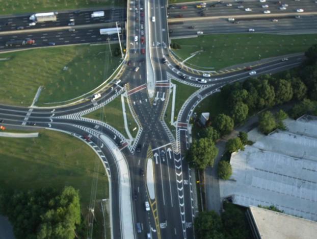
16 Exhibit 1-3. First constructed DDI in Utah at Pioneer Crossing and Interstate 15 (American Fork, UT). (1) 6

 Exhibit 1-5.")
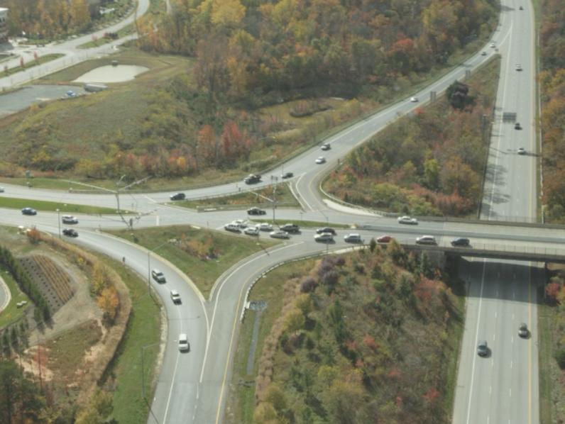
17 Exhibit 1-4. First constructed DDI in Georgia at Ashford Dunwoody Road near Perimeter Market. (2) Exhibit 1-5. First constructed DDI in Minnesota at Highway 15. (3) 7

 Exhibit 1-7.")
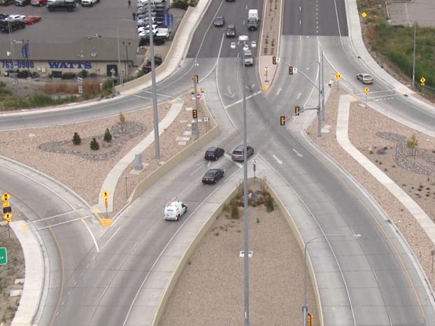
18 Exhibit 1-6. First constructed DDI in Idaho at Interstate 86 and US 91/Yellowstone Highway (Pocatello-Chubbuck, ID). (4) Exhibit 1-7. Crossover location at the DDI located at SR 92 and Interstate 15 (Utah County, UT). (5) 8


19 Exhibit 1-8. Overhead signing at the DDI located at SR 92 and Interstate 15 (Utah County, UT). (5) Exhibit 1-9. Pedestrian crossing at the right-turn lane of the exit located at Pioneer Crossing and Interstate 15 DDI (American Fork, UT). (6) 9
 GEOMETRIC DESIGN CONSIDERATIONS The fundamental design features of the DDI are the directional crossovers on either side of the interchange, which ultimately improve the operations of turning")
20 Exhibit Sidewalk and recessed lighting located on the bridge at the Pioneer Crossing and Interstate 15 DDI (American Fork, UT). (6) GEOMETRIC DESIGN CONSIDERATIONS The fundamental design features of the DDI are the directional crossovers on either side of the interchange, which ultimately improve the operations of turning movements to and from the freeway facility. The geometric design necessary to allow for these crossover movements results in the use of reverse curvatures in advance of the interchange as vehicular traffic is directed to the right before it can cross to the left. Several overarching principles guide users in conceptualizing and designing DDIs. The following principles may support DDI concept development, considering the context of the interchange and nearby adjacent intersections: Accommodate design vehicles at the crossover ramp terminal junctions Promote reduced and consistent design speeds through the interchange Channelize inbound and outbound movements in the crossover design at each intersection to guide drivers to use the intended lanes and discourage wrong-way movements Create a vehicle path alignment directing vehicles into appropriate receiving lanes DDI concept design involves balancing and optimizing trade-offs associated with user performance, capacity, costs, maintenance, and construction staging, among other items. For instance, considering heavy vehicle design at the crossover may lead designers to contemplate larger design radii or wider lanes; however, this could promote higher speeds through the 10


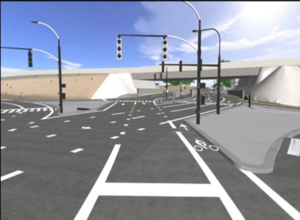
21 crossover for other vehicle types. Instead, to provide adequate facilities for the design vehicle while maintaining safe speeds for other motorists, designers may want to consider designs that offset one or more of the approaches to the DDI. This method may increase street alignment radii, resulting in comparatively narrower lanes to serve design vehicle over tracking. These and other tradeoffs of DDI geometric design are discussed in detail in Chapter 7. Exhibits 1-11 and 1-12 illustrate typical designs for an overpass and underpass at a DDI. Exhibit DDI (overpass) at 500 East American Fork (American Fork, UT). (1) Exhibit DDI (underpass) at Dorsett Road and Interstate 270 (St Louis, MO). (7) 11
22 RESOURCE DOCUMENTS This DDI guide is supplemental to major resource documents including but not limited to: A Policy on Geometric Design of Highways and Streets (American Association of State Highway and Transportation Officials [AASHTO] Green Book) (8) Highway Capacity Manual (HCM) (9) Manual on Uniform Traffic Control Devices (MUTCD) (10) Highway Safety Manual (HSM) (11) Other research documents that appear in this guide and are more specialized to specific areas of the guide include various National Cooperative Highway Research Program (NCHRP) reports, Transportation Research Board (TRB) papers, and FHWA publications The following supplemental resource documents related to the DDI are available: FHWA Tech Brief on Double Crossover Diamonds (FHWA-HRT ) (12) FHWA Alternative Intersection/Interchanges: Informational Report (AIIR) (FHWA- HRT ) (13) FHWA Project DTFH61 10 C 00029: Operational and Safety Evaluation of Double Crossover Diamonds. Year 1 and Year 2 Project reports (14) FHWA Saxton Transportation Lab Project : HCM Chapters/Guidance for Alternative Intersections/Interchanges. New HCM methodologies for DDI (15) MODOT Report: Missouri s Experience with the Diverging Diamond Interchange (16) MODOT Diverging Diamond Interchange Performance Evaluation (I-44 & Route 13) (17) Kentucky Transportation Cabinet DDI Evaluation Study (18) FHWA Driver Evaluation of the Diverging Diamond Interchange (FHWA-HRT ) (19) 12
23 CHAPTER 2 POLICY AND PLANNING This chapter contains guidance on how to consider alternative intersections and interchanges in general and a DDI in particular. This chapter summarizes policy and planning considerations related to a DDI. The remaining chapters of this guide will provide specific details of the multimodal, safety, operations, geometric design, and traffic control features of a DDI. Alternative intersections are often initially considered for operational or safety needs, and other key factors may include spatial requirements and multimodal needs. This chapter provides approximate footprints for different types of DDIs to allow for planning-level screening and feasibility analysis. PLANNING CONSIDERATIONS FOR ALTERNATIVE INTERSECTIONS AND INTERCHANGES Alternative intersection evaluations may vary depending on the stage of the project development process. Each project stage can affect how each of the policy and technical considerations is assessed. While the operational, design, safety, human factors, and signing controls should be considered at every stage of the development process, a planning-level design evaluation may not require the same level of analysis or detailed evaluation as projects in later development stages. Evaluations should be as comprehensive as needed to answer key project questions for each unique project context. Serving Pedestrians and Bicycles A DDI offers an excellent opportunity to integrate multimodal facilities into an interchange. Almost all of the DDIs constructed to date included some combination of pedestrians, bicyclists, or transit facilities. The reduced number of signal phases can make it easier to serve non-motorized movements compared to a multi-phase signal. The two-phase DDI signal in most cases provides sufficient time per phase to serve pedestrians. Any pedestrian clearance phases are further minimized, as crossing distances are shortened to only cross one direction of traffic at a time. Through the separation and channelization of the two directions of vehicular traffic, pedestrians only have to interact with one direction of traffic at a time. This simplifies the pedestrian gap acceptance process and reduces the risk for pedestrian-vehicle conflicts provided pedestrians understand which direction traffic is coming from. The reduced crossing distances can also benefit bicyclists by reducing exposure time within the intersection (crossover) and minimizing the chance for vehicular conflicts. Some DDIs to date have been constructed with bicycle lanes through the crossovers, providing dedicated right-ofway for those road users. Several others have been constructed with bicycle facilities in the form of shared-use paths on the outside of the interchange. While there are many opportunities for multimodal accommodations at a DDI, these design elements are not without challenges. Chapter 3 of this guide discusses challenges and 13
24 considerations, and provides recommendations for how to achieve safe and efficient provisions for multimodal users of a DDI. Traffic Volume Relationships Exhibit 2-1 conceptually depicts the relationship of conventional intersections, alternative intersections, and grade separations in their ability to serve increasing traffic volumes. Exhibit 2-1. Relationship between volume and interchange type. 14
25 The DDI is an alternative to the conventional diamond interchange, as well as other interchange forms like a single-point interchange or a partial cloverleaf. The primary difference between a DDI and a conventional diamond interchange is the design of directional crossovers on either side of the interchange. This eliminates the need for left-turning vehicles to cross the paths of approaching through vehicles. Cross street traffic is shifted to the left side of the street between the signalized ramp intersections. Drivers on the cross street who are making a left turn onto the ramps are allowed to continue to the ramps without conflicting with opposing through traffic and without stopping. The DDI design has shown to improve the operations of turning movements to and from the freeway facility, as well as significantly reduce the number of vehicle-to-vehicle conflict points compared to a conventional diamond interchange. STAKEHOLDER OUTREACH Similar to other transportation projects, stakeholder outreach is a critical part of the overall planning process. Successfully implementing the first DDI in a community may benefit from explicit and proactive outreach and education to affected stakeholders and the general public. This would create opportunities to familiarize others with how the intersections work while creating opportunities to hear of general project and DDI specific issues and considerations. Special considerations may include minimizing the likelihood of a wrong-way maneuver into opposing traffic. The greater the crossing angle, the more the intersection will appear to intersect in a familiar manner. Public information and educational campaigns prior to opening a DDI intersection can help promote an understanding of unique features. Creating multiple forums to engage the public (including presentations at local council or board meetings, briefs at community organization functions, and project-specific open house meetings) results in opportunities to listen to community interests and share objective information about the interchange form. Exhibit 2-2 and Exhibit 2-3 are two examples of using video animation to describe how to travel through a DDI. The video clip includes animation and narration to provide the general public with a clear message of how a DDI functions. Both videos were included on the Utah Department of Transportation (UDOT) and Nevada DOT project websites. Exhibit 2-4 is an example of a fact sheet of how to travel through a DDI with an emphasis on all users of the system. The fact sheet highlights how a pedestrian, bicyclist, and motorist would travel through a DDI in Minnesota. 15


 16")
26 Exhibit 2-2. Example video screen captures from UDOT of how to travel through a DDI. (1) Exhibit 2-3. Example video screen capture from Nevada DOT of how to travel through a DDI. (20) 16
 Exhibit 2-5 is an example of a DDI explanation brochure used by Missouri Department of Transportation (MoDOT) for a DDI.")
27 Exhibit 2-4. Fact sheet from Minnesota DOT on how various users travel through a DDI. (3) Exhibit 2-5 is an example of a DDI explanation brochure used by Missouri Department of Transportation (MoDOT) for a DDI. Once the interchange is open to the public, monitoring driver behavior and using law enforcement as necessary to promote proper use of the new form can aid driver acclimation. 17

28 Exhibit 2-5. Public outreach brochure used by MoDOT. (7) Exhibit 2-6 is an example of a DDI branding campaign used by Georgia Department of Transportation (GDOT) and local improvement district. The branding campaign included a website, a unique logo, and slogan titled, Can You DDI? Arrive-Crossover-Drive. This branding effort provides the public with an easy, identifiable look to this planned urban DDI. 18
 FHWA has created alternative intersection and interchange informational videos and video case studies, which can be viewed on the FHWA YouTube channel (https://www.youtube.com/user/usdotfhwa).")
29 Exhibit 2-6. Example public outreach brochure used by GDOT. (2) FHWA has created alternative intersection and interchange informational videos and video case studies, which can be viewed on the FHWA YouTube channel ( (21) In addition, FHWA has developed alternative intersection brochures that can be found on the FHWA website ( (22) Examples of this information are shown in the appendix. 19
30 POLICY CONSIDERATIONS Designing, operating, and managing a street and its intersections should align with the appropriate jurisdictional policies associated with that facility. The facility location and type can often dictate the appropriateness of the right-of-way and access management needs associated with alternative intersections. The degree to which motor vehicle throughput should or should not be prioritized over other modes also plays a role in determining the appropriateness of alternative intersections at specific locations. Some of the considerations that should be addressed before construction of a DDI include the following: Access management considerations Operational measures of effectiveness Pedestrian facilities with access and wayfinding for persons with disabilities, including the requirements of the Americans with Disabilities Act (ADA) and Section 504 (the Rehabilitation Act) (23) Bicycle facilities Managed lane scenarios, including ramp metering Snow removal and storage Design vehicle Incident management Emergency response needs Access Management The subject of adjacent intersections has been one of the biggest concerns noted by practitioners building and operating DDIs as well as by academics who study the effects of DDIs on operations and safety. Adjacent intersections are problematic for many interchange configurations that may be considered as a replacement to conventional diamond interchanges; the specific issues relative to the DDI are discussed here. From an operational perspective, the DDI s efficient two-phase signals provide much higher throughput than nearby adjacent signals that often allow many more signal phases. This, combined with the close proximity of the adjacent intersection, causes limited queue storage and spillback into the DDI. To the motoring public, the DDI design will often appear to be a wasted effort when in fact the DDI is operating as intended. Safety concerns arise for motorist turning right from an exit ramp and weaving across traffic to make a left at the adjacent intersection, especially if right turn on red (RTOR) operations are allowed at the exit ramps. 20
31 Transportation agencies considering the DDI with nearby signalized intersections and congested cross roads have had to make geometric and signal design modifications to nearby intersections. Some potential geometric treatments that could improve operations and/or safety include: Relocating an intersection to the next closest signalized intersection if nearby. This treatment was used at Dorsett Road in Maryland Heights, MO. Using grade separation to eliminate one or more signal phases at the intersection. This treatment was used at National Avenue in Springfield, MO where a left turn into the hospital was modified to take a right, followed by another immediate right turn that looped around and under the cross road using an underpass. Alternative intersection designs could be used to reduce the number of necessary signal phases at adjacent intersections along the corridor. This treatment has yet to be used in practice; however, an entire corridor of alternative intersection designs is being designed along Poplar Tent Road in Charlotte, NC. PLANNING CONSIDERATIONS Transportation professionals should address the following planning considerations when developing an alternative intersection design: Community goals Outside of formalized land use policies, cities and communities often have general goals that provide insights about the nature and character of their community. These goals can range from concepts that preserve a historic character or identified heritage. Some goals may be to create walkable communities or complete streets. Other goals can be to encourage economic development by preserving existing business or residential areas while encouraging thoughtful development. Regardless of the specific goals or vision, these considerations may influence street and intersection design. Surrounding land uses and zoning DDI intersections are well suited for suburban and urban environments. They are more challenging to implement on streets with nearby adjacent traffic signals or numerous driveways. Project context Key questions that help to identify key stakeholders for a particular project might include: o What is the purpose and function of the existing or planned road facilities? o What are the existing and planned land uses adjacent to and in the vicinity of the road facilities? o Who will likely desire to use the road facilities given the existing and planned land uses? o What are the existing and anticipated future socio-demographic characteristics of the populations adjacent to and in the vicinity of the existing or planned road facilities? 21
32 o What are the perceived or actual shortcomings of the existing road facilities? o Who has jurisdiction over the facility? o Where is capital funding for the project originating (or expected to originate)? o Who will operate and maintain the facility? Multimodal considerations As with any street segment or intersection, each configuration must consider and serve the various users who currently or may be expected to use the facilities. This includes pedestrians and bicyclists and can also include users with special needs such as the visually impaired, elderly users, or young users. Access management Access near a DDI needs to be restricted based on local, state, and federal requirements for intersection spacing. Design vehicles The interchange geometry will need to accommodate transit, emergency vehicles, freight, and potentially oversize and overweight (OSOW) vehicles. PLANNING CHALLENGES The following are several challenges associated with planning DDIs: Overpass or underpass The decision to build over or under the limited access facility can have adverse effects on the operation and safety of various transportation modes. Driver education Successful implementations of DDIs are often preceded by public outreach and education campaigns, which are typically not conducted for conventional intersection improvements. Driver expectation DDIs relocate through and left-turn movements at the crossovers from their conventional location. This is different from what most drivers would expect and must be accounted for in the intersection planning and design. Multimodal accommodation As with any street segment or intersection, each configuration must consider and serve the various users who currently or may be expected to use the facilities. This should always include pedestrians and bicycles, understanding that the exact provisions may necessarily vary from site to site. However, pedestrian facilities must always be made accessible. DDI intersections are generally compatible with transit as well. Sufficient right-of-way Right-of-way constraints may limit a designer s ability to provide safe movement of vehicles through the crossover or limit the use of alternative design configurations. 22
33 Proximity to adjacent intersections Nearby adjacent intersections have been found to hinder the ability of the DDI to process traffic as efficiently as it was intended. PROJECT PERFORMANCE CONSIDERATIONS Measuring the effectiveness of a project s overall performance depends on the nature or catalyst for the project. Understanding the intended specific operational, safety, and geometric performance context for each intersection or corridor including intended users can help determine project-specific performance measures. The project performance may be directly linked to the specific design choices and the specific performance of the alternatives considered. The project performance categories described below can influence and are influenced by the specific DDI design elements and their characteristics. (24) Accessibility Chapter 3 of this guide describes accessibility as it relates to special consideration given to pedestrians with disabilities including accommodating pedestrians with vision or mobility impairments. However, for the purposes of considering a project s general context and the performance considerations, the term accessibility goes beyond the conversation of policy related to ADA and Public Rights-of-Way Accessibility Guidelines (PROWAG) and is meant to be considered in broader terms. (23) With respect to considering applicable intersection forms for a given project context, accessibility is defined broadly as the ability to approach a desired destination or potential opportunity for activity using highways and streets (including the sidewalks and/or bicycle lanes provided within those rights-of-way). This could include the ability for a large design vehicle to navigate an intersection as much as it might pertain to the application of snow mobiles or equestrian uses in some environments or conditions. Mobility Mobility is defined as the ability to move various users efficiently from one place to another using highways and streets. The term mobility can sometimes be associated with motorized vehicular movement and capacity. For the purposes of this guide, mobility is meant to be independent of any particular travel mode. Quality of Service Quality of service is defined as the perceived quality of travel by a road user. It is used in the 2010 HCM to assess multimodal level of service (MMLOS) for motorists, pedestrians, bicyclists, and transit riders. Quality of service may also include the perceived quality of travel by design vehicle users such as truck or bus drivers. Reliability Reliability is defined as the consistency of performance over a series of time periods (e.g., hourto-hour, day-to-day, year-to-year). 23
34 Safety Safety is defined as the expected frequency and severity of crashes occurring on highways and streets. Expected crash frequencies and severities are often disaggregated by type, including whether or not a crash involves a non-motorized user or a specific vehicle type (e.g., heavy vehicle, transit vehicle, motorcycle). In cases where certain crash types or severities are small in number, as is often the case with pedestrian- or bicycle-involved, it may be necessary to review a longer period of time to gain a more accurate understanding. PROJECT DEVELOPMENT PROCESS For the purposes of this report, the project development process is defined as consisting of the stages described below. Federal, state, and local agencies may have different names or other nomenclature with the overall intent of advancing from planning to implementation. Exhibit 2-7 illustrates the overall project development process. Planning Studies Exhibit 2-7. Project development process. Planning studies often include exercises such as problem identification and other similar steps to ensure there is a connection between the project purpose and need and the geometric concepts being considered. Planning studies could include limited geometric concepts on the general type or magnitude of project solutions to support programming. Alternatives Identification and Evaluation The project needs identified in prior planning studies inform concept identification, development, and evaluation. At this stage, it is critical to understand the project context and intended outcomes so potential solutions may be tailored to meet project needs within the opportunities and constraints of a given effort. FHWA describes context sensitive solutions as a collaborative, interdisciplinary approach that involves all stakeholders in providing a transportation facility that fits its setting. (25) In considering the concept of context sensitive design/solutions, this stage calls for the meaningful and continuous stakeholder engagement to progress through the project development process. 24
35 Preliminary Design Concepts advancing from the previous stage are further refined and screened during preliminary design. For more complex, detailed, or impactful projects, the preliminary design (typically 30- percent design level plans) and subsequent documentation are used to support more complex state or federal environmental clearance activities. The corresponding increased geometric design detail allows for refined technical evaluations and analyses that inform environmental clearance activities. Preliminary design builds upon geometric evaluations conducted as part of the previous stage (alternatives identification and evaluation). Some of the common components of preliminary design include: Horizontal and vertical alignment design Typical sections Grading plans Structures Traffic/intelligent transportation systems (ITS) Signing and pavement markings Illumination Utilities Final Design The design elements are advanced and refined in final design. Typical review periods include 60- percent, 90-percent, and 100-percent plans before completing the final PS&E. During this stage, there is relatively little variation in design decisions as the plan advances to 100-percent. Functionally, in this stage of the project development process, the targeted performance measures have a lesser degree of influence on the form of the project. Construction Construction activities could include geometric design decisions related to temporary streets, connections, or conditions that facilitate construction. Project performance measures may relate to project context elements. SUMMARY OF DDI ADVANTAGES AND DISADVANTAGES As described in Chapter 1 and the previous sections of this chapter, DDIs have unique features and characteristics, including multimodal considerations, safety performance, operations, geometric design, spatial requirements, constructability, and maintenance. 25
36 Exhibit 2-8 provides an overview of the primary advantages and disadvantages of DDIs for users, policy makers, designers, and planners should to understand when considering this type of alternative intersection form. 26
37 Exhibit 2-8. Summary of DDI advantages and disadvantages. Advantages Disadvantages Non-motorized users Reduces conflicts between vehicles and pedestrians Pedestrians may have to cross unsignalized, for most crossing movements channelized right and left turns onto freeway Opportunity to safely accommodate pedestrians Pedestrians may be unaware what direction traffic is and bicyclists through interchange coming from Creates shorter pedestrian crossing distance for Center walkway may be unfamiliar to pedestrians some movements Opportunity for bicycle lanes and multi-use paths through additional right-of way (no left turn lanes needed) Provides two-stage crossing opportunities Safety Reduced conflict points over other interchange May have potential for wrong-way maneuvers at forms crossovers Reduction from 10 to 2 crossing conflicts Unusual sight distance considerations at crossovers compared to standard diamond and ramp movements Operations Two-phase signals reduce lost time at interchange Potential lower right-turn capacity from freeway and increase capacity where RTOR not allowed Left-turns onto freeway may be free-flowing Challenging to coordinate through traffic in both Ability to coordinate through traffic or left turns from freeway directions Increased operational challenges at adjacent Potential for significant delay and travel time savings over standard diamond intersections due to crossover, two-phase operation at DDI Significantly reduced queue spillback potential, especially between ramp terminals Potential driver unfamiliarity with crossover design and merges from left Access Management Provide full access control through interchange Does not allow exit ramp to entrance ramp movement Reduced speed through the interchange from crossover geometry and reverse curves Traffic Calming May require access control beyond interchange to prevent weaving maneuvers May require relocating or removal of adjacent streets/driveways to accommodate crossover and reverse curves Turns onto the freeway may have high speeds due to lack of signal control Space Generally fits within existing interchange right-ofway Some additional ROW width may be needed to and bridge structure accommodate crossovers at tight diamonds due to Lower footprint compared to parclo interchanges reverse curves Construction and Maintenance Generally fits on or under existing bridge structure May require additional lighting due to unique Low-cost design compared to other interchange geometry forms Additional signage and pavement markings are Less queuing on the arterial may reduce pavement needed beyond the levels of a conventional diamond rutting and wear interchange More complex signal design requires early consideration in design 27
38 This page intentionally left blank. 28
39 CHAPTER 3 MULTIMODAL CONSIDERATIONS This chapter presents guidance for accommodating pedestrians, bicyclists, transit, and heavy vehicles at a DDI. While many existing interchanges do not have accommodations for pedestrians, bicyclists, or transit, almost all of the DDIs constructed to date included some combination of such facilities. The overall objective is to develop a design, regardless of the type of intersection, compatible with a Complete Street. A Complete Street is a facility that serves many types of users including freight, transit, and non-motorized users. This chapter discusses both the challenges and benefits of DDIs as an alternative intersection choice that is safe and efficient for multimodal users. Multimodal benefits of DDIs include: Reduced overall right-of-way footprint compared to a conventional diamond interchange Two-phase traffic signal control with reduced pedestrian wait time Minimized crossing distances Simplification of conflicts to one-directional vehicular traffic Opportunities for bicycle lanes and multiuse paths through the interchange Some of the challenges of multimodal provisions at DDIs include: Altered travel paths with travel in the center of the interchange between vehicular lanes Traffic approaching from unexpected directions Unfamiliar signal phases Uncontrolled crossing of turn lanes The reduced number of signal phases can make it easier to serve non-motorized movements compared to a multi-phase signal. At multi-phase signals, the need to provide adequate pedestrian clearance may result in the pedestrian movement controlling the phase lengths, leading to longer cycle lengths and greater pedestrian delay. In contrast, vehicle movements typically control phase length at two-phase DDI signals, which most often provide sufficient time per phase to also serve pedestrians. Although pedestrian crossings at the crossovers are signalized, pedestrian crossings of the turn lanes to and from the freeway may not be signalized. These potentially uncontrolled crossing locations require special attention and consideration to assure pedestrian safety. A DDI avoids the need for left-turn pockets within the interchange, which frees up right-of-way compared to a conventional diamond. This right-of-way can be used for multimodal facilities in the form of sidewalks, bicycle lanes, or even transit facilities. 29
40 At the crossover pedestrian signals, pedestrian clearance phases are generally short as crossing distances are shortened to only cross one direction of traffic at a time. At the same time, pretimed DDI signals can provide for extended pedestrian walk phase times, which can reduce pedestrian delay, and can provide added time for pedestrians with disabilities. The reduced crossing distances can also benefit bicyclists, who have a reduced exposure time within the crossover intersection, thereby minimizing the chance for vehicular conflicts. Finally, through the separation and channelization of the two directions of vehicular traffic, pedestrians interact with one direction of traffic at a time. This simplifies the pedestrian gap acceptance process and reduces the risk for pedestrian vehicle conflicts, provided pedestrians understand from which direction traffic is coming from at a given crossing. DESIGN PRINCIPLES AND APPROACH The fundamental design features of the DDI are the ramp terminal intersection directional crossovers serving movements to and from the freeway facility. The geometric design necessary to allow for these crossover movements can result in reverse curvature in advance of the crossover. These bulb-outs can result in a locally wider right-of-way footprint and large channelization islands that provide opportunities for providing pedestrian and bicycle facilities. Similarly, the two directions of through traffic within the interchange are often separated by a median (again a function of the bulb-outs needed for the crossover), that could be used for a share-use pathway between the streets. These features result in several options for locating pedestrian and bicycle facilities, as illustrated in the schematic in Exhibit 3-1. Exhibit 3-1. Schematic of DDI right-of-way availability for multimodal facilities. 30

41 Exhibit 3-1 illustrates possible locations for multimodal facilities in the center of the interchange or outside of the traffic lanes. Multimodal facilities on the outside are common for most transportation facilities and interchanges, but the DDI also provides room in the center between the two through movements. Large channelization islands between the crossovers, bulb-outs, and channelized turn lanes provide additional room to locate facilities. The right-of-way can also be used to add bicycle lanes adjacent to the travel lanes. Anticipating Multimodal Needs, Behavior, and Patterns A fundamental challenge in developing any new intersection or interchange form is deciding how to best provide for pedestrian and bicycle movements, and anticipating the desire lines between different origins and destinations for these modes (e.g., how they travel through the intersection or interchange). Forecast volumes for non-motorized users are rarely available, and if they are, they typically do not capture travel patterns within the intersection or interchange. However, the majority of DDIs constructed to date feature pedestrian and bicycle facilities. For many retrofit sites, the existing pedestrian and bicycle facilities were improved with construction of the DDI. For example, DDIs at MO 13 in Springfield, MO; Dorsett Road in Maryland Heights, MO; and Harrodsburg Road in Lexington, KY all added shared-use paths through the interchange (see Exhibits 3-2, 3-3, and 3-4). At all three of these sites, the construction of multimodal facilities was a priority for agencies, garnering positive feedback from local residents and users of the facility. At interchanges, land use development can sometimes lag interchange construction, resulting in pedestrian and bicycle needs to not be apparent from opening day. But early consideration and provision for pedestrian and bicycle movements should be a priority consideration for any DDI, and should be accounted for in even early design concepts. Exhibit 3-2. Center walkway at MO 13 (Springfield, MO). (14) 31
 This chapter describes the unique characteristics of the four primary non-auto modes (pedestrians, bicyclists, transit, and heavy vehicles) that should be considered when analyzing and designing")
42 Exhibit 3-3. Outside walkway at Dorsett Road (Maryland Heights, MO). (14) Exhibit 3-4. Shared-use path on outside at Harrodsburg Road (Lexington, KY). (14) This chapter describes the unique characteristics of the four primary non-auto modes (pedestrians, bicyclists, transit, and heavy vehicles) that should be considered when analyzing and designing DDIs. The transportation professional needs to work to identify and understand the needs of these various users in order to produce a balanced design that serves them all. PEDESTRIANS The inclusion of pedestrian facilities should receive attention and consideration throughout the design process. This section describes DDI design features, considerations, and trade-offs relating to the pedestrian mode. Pedestrian facilities should be planned, designed, and constructed to emphasize pedestrian convenience and safety, which is achieved through appropriately sized sidewalks, vertical and horizontal separation from adjacent travel lanes, minimized pedestrian crossing distances, clearly defined pedestrian paths, adequate time to cross, and low vehicular speeds. Landscaping and other aesthetic treatments can contribute to a positive pedestrian experience. 32
43 Pedestrians Outside Versus Center Pedestrian facilities can be provided as walkways outside the vehicular through travel way (standard for most diamond interchanges with pedestrian facilities) or as a walkway in the median, between the vehicular directions of travel. For an overpass DDI, pedestrian facilities in the center of the interchange (within the median) may be recommended to minimize conflicts with left-turning traffic to and from the freeway and to allow crossing the interchange in all directions i.e., travel along the arterial and crossing the arterial from one side to the other). For underpass DDIs, pedestrian walkways may need to be located on the outside to avoid conflicts with bridge columns placed between the two directions of vehicular traffic. A concern for outside pedestrian facilities is the lack of marked crosswalks to allow pedestrians to cross the arterial street at the DDI. While this has been the practice at many DDIs with outside facilities to date, it is not desirable as it requires pedestrians to travel to the next adjacent signal to cross the arterial. As many DDIs are associated with access management treatments and relocated adjacent intersections, the additional travel distance for pedestrians to the next crossing opportunity may be large, and may result in frequent non-compliance and jaywalking by pedestrians. It should be expected that pedestrians will need and want to cross the arterial, and the presence of transit facilities or certain types of development will only make this more likely. It is strongly recommended that all pedestrian movements be provided for at any intersection, including a DDI interchange. Exhibit 3-5 gives an example of a pedestrian facility located in the center of the DDI (MO 13 in Springfield, MO). Example 3-6 gives an example of an outside pedestrian walkway (Dorsett Road in Maryland Heights, MO). The center facility is at an arterial overpass, while the outside facility is at an arterial underpass. In general, both configurations are feasible for both arterial overpasses and underpasses, although with some challenges as discussed below. The exhibits further highlight which crossings have pedestrian signals, and which are unsignalized crossings. For pedestrian crossings without signals, vehicle movements should be controlled to assure pedestrian safety and comfort by controlling vehicle speeds, and supplementing the crossing with pedestrian safety enhancements including a raised crosswalk, high-visibility markings, or rectangular rapid-flashing beacons (RRFB). In some cases, a pedestrian signal may be needed to assure driver compliance with the pedestrian crossing. Higher-speed and free-flowing vehicle turning movements should only be used where pedestrian facilities are not present. For multilane turns with pedestrian crossings, pedestrian signals are required to make the crossing accessible to pedestrians with disabilities. Additional information related to special consideration given to pedestrians with disabilities including accommodating pedestrians with vision or mobility impairments can be found in the policies related to ADA and Public Rights-of-Way Accessibility Guidelines (PROWAG). (23) 33
 In the case of the overpass with center walkways in Exhibit 3-5, traffic signals are needed to control vehicle crossover movements.")
44 Exhibit 3-5. Pedestrian facilities in center of DDI (Springfield, MO). (26) In the case of the overpass with center walkways in Exhibit 3-5, traffic signals are needed to control vehicle crossover movements. Pedestrian facilities to cross into the center can be colocated with these vehicle signals, and a pedestrian crossing phase provided with the concurrent vehicle phase. The right turns are shown as unsignalized pedestrian crossings and should be configured in a way to promote low vehicle speeds, good sight distance to the crosswalk, and high driver yielding behavior. Additional treatments are available to further promote yielding. In general, the center walkway needs to be separated by a barrier wall for pedestrian comfort and safety. The center walkway should not be extended to adjacent intersections outside the interchange. In the case of the underpass with outside walkways in Exhibit 3-6, pedestrians in each direction cross four vehicle turn lanes with eight total pedestrian crossings. These can all be unsignalized, but may be signalized for pedestrian safety or enhanced with other treatments that may improve yielding. In this example the right-turn off the freeway is signalized, and the right-turn to the freeway is unsignalized. Notice that in this case, no pedestrian crossing of the arterial street is provided, which is undesirable. An example of pedestrian-focused design of a DDI sidewalk along the perimeter that also allows for an arterial crossing is discussed in a later section. 34
 The advantages and challenges of center and outside pedestrian facilities are summarized in Exhibits")
45 Exhibit 3-6. Pedestrian facilities on outside of DDI (Maryland Heights, MO). (26) The advantages and challenges of center and outside pedestrian facilities are summarized in Exhibits 3-7 and 3-8, respectively. 35
46 Exhibit 3-7. Center walkway pedestrian safety and comfort. Street Crossings Walkway Facility Advantages Crossing of the arterial street provided at DDI for full pedestrian access Crossing one direction of traffic at a time Short crossing distances No exposure to free-flowing left turns to freeway Protected signalized crossing to walkway Pedestrian clearance time generally provided in crossover signal phasing Pedestrian delay to center minimized by short cycles at two-phase signals Side walls provide a positive barrier between vehicular movements and pedestrians Walls low enough to avoid tunnel effect that could impact pedestrian comfort Recessed lighting can provide good illumination of walkway Challenges Crossing of free-flow right-turn movements to/from freeway Pedestrians may not know to look to the right when crossing to center Wait at center island dictated by length of signal phase for through traffic Location of pedestrian signals can conflict with vehicular signals at crossovers Center walkway placement counter to typical hierarchy of street design Potential discomfort from moving vehicles on both sides of walkway Sign and signal control clutter 36
47 Exhibit 3-8. Outside path/sidewalk pedestrian safety and comfort. Advantages Crossing one direction of traffic at a time Ramp crossing distances are often shorter than through traffic crossing distance due to fewer travel lanes Challenges Crossing of free-flow right-turn movements to/from freeway Conflict with free-flow left turns to freeway, where fast vehicle speeds are likely (acceleration to freeway) Street Crossings Walkway Facility Extension of existing pedestrian network (natural placement on outside of travel lanes) Pedestrian typically has view of path ahead (depends on sight lines and obstructions) Walkway doesn't conflict with center bridge piers (at underpass) Opportunity to use right-of-way outside of bridge piers (at underpass) Crossing of the arterial street sometimes not provided at DDI Potential sight obstruction of pedestrian crossing left turns from behind barrier wall Pedestrians may not know which direction to look in, when crossing turn lanes Unnatural to look behind to check for vehicles before crossing when traveling out of the DDI (depends on angle of approach and direction of travel) Signalized crossings require more complicated timing Need for widened structure on outside for overpass Potential for additional right-of-way for underpass or construction of retaining wall under bridge Need for additional lighting for underpass Pedestrian-Focused DDI Design In general, pedestrian safety and comfort can be enhanced by reducing vehicle speeds, improving sight distances between drivers and pedestrians, and appropriately locating the crosswalks. At DDIs, the required channelized right and left-turn lanes to and from the freeway presents an opportunity for pedestrian-focused designs through the use of reduced curve radii and other geometric changes. Exhibits 3-9 and 3-10 illustrate this concept for a DDI with center walkway and a DDI with outside facilities, respectively. 37
48 Exhibit 3-9. Pedestrian-focused DDI center walkway. 38
49 Exhibit Pedestrian-focused DDI outside walkway. The key concepts underlying pedestrian-focused design of DDIs include four primary principles: Tighten vehicle curve radii to reduce speeds at the crosswalk. Lower vehicle speeds have been linked in research to increased driver yielding rates, as well as lower risk of serious injury or death for the pedestrian in the case of a crash. Provide adequate sight distance for vehicle approaches to crosswalks by locating the crosswalk in the tangent portion of the approach, or in the beginning portions of the curve. A crosswalk located in the middle of a large swooping turn is difficult for drivers to see and react to. Improved vehicle sight distance also provides enhanced pedestrian sight distance to make adequate gap crossing decisions at unsignalized crossings. Provide one vehicle length of storage downstream of the crosswalks for yield-controlled vehicle movements. Similar to the crosswalk placement at roundabouts, this separates the driver decision points of yielding to pedestrians at the crosswalk and screening for gaps at the yield sign. It also prevents drivers waiting at the yield line from blocking the crosswalk with their vehicle. Locate crosswalks behind the stop bar for signalized vehicle turns, consistent with driver and pedestrian expectations at signalized intersections. 39
50 These configurations apply equally to DDIs with center walkway or outside pedestrian facilities. One key difference between the two is that the turn radius for the left-turns to and from freeways can be selected independent of pedestrian considerations for the center walkway, because pedestrians do not cross these turn movements with a center walkway DDI configuration. Conflict Points Anywhere a pedestrian walkway crosses vehicular travel lanes, a pedestrian vehicle conflict point exists. The number and type of conflict points for a DDI with center and outside walkways are illustrated in Exhibits 3-11 and 3-12, respectively. Note that a center walkway inherently enables pedestrians to cross from one side of the arterial to the other. For outside walkways an opportunity to cross the arterial street should be provided, although some existing DDIs did not provide crossings of the arterial. In those cases crossings of the arterial would have to take place at an upstream or downstream intersection, which is undesirable. The exhibits distinguish between conflict points where vehicles are stopped at signals or decelerating, and those where vehicles are more likely to be free-flowing or accelerating. Free-flow vehicles may also be present at the first type of conflict points (for example when the vehicle signal is green), but there are at least some intervals in the signal cycle where traffic is stopped at those locations. For the free-flow or accelerating conflict points, traffic rarely has to stop or slow down, other than when drivers yield to pedestrians. Exhibit Pedestrian-vehicle conflict points at DDI with center walkway. 40
51 Exhibit Pedestrian-vehicle conflict points at DDI with outside walkways. Exhibit 3-11 shows a total of eight pedestrian-vehicle conflict points for the center walkway. Two of these conflict points are free-flowing or accelerating (right turns to the freeway), while the other six conflict points are stopped or decelerating, with traffic having to stop at regular intervals. For the outside walkway, a total of twelve conflict points exist if pedestrian facilities are also provided to cross the arterial street. Four of the conflict points are accelerating and the remaining eight are decelerating. The two additional accelerating conflict points, compared to a center walkway, are for the free-flowing left-turn movements onto the freeway. These movements require designers to use extra care and attention to assure a safe pedestrian crossing, as discussed below. Note that the diagrams depict a single lane in each direction of travel, while DDIs are typically constructed at interchanges were the arterial has multiple through lanes in each direction. In practice, a mainline crossing will likely have more conflict points than a channelized turn lane crossing. For comparison, Exhibit 3-13 shows pedestrian-vehicle conflict points for a typical diamond interchange with channelized right turns. Exhibit 3-14 shows the pedestrian-vehicle conflict points for a typical diamond interchange with pedestrian crossing of the arterial. The diamond interchange has a total of eight conflict points for pedestrians with four decelerating and four accelerating points. When a crossing of the arterial is provided, an additional four decelerating conflict points are created. 41
52 Exhibit Pedestrian-vehicle conflict points at conventional diamond. Exhibit Pedestrian-vehicle conflict points at conventional diamond with pedestrian crossing of arterial. In summary, a DDI with center walkways has six stopped or decelerating and two free-flow or accelerating conflict points, while the DDI with outside walkways has eight stopped and four free-flow conflicts. Overall, a DDI with center walkway minimizes the overall number of conflict points, including accelerating conflicts, while providing full access of pedestrians to also cross the arterial street. 42

53 Exhibit Pedestrian-vehicle conflict point comparison. DDI with outside walkways Conventional diamond with pedestrian crossing Type of conflict DDI with center walkway Conventional diamond Free-flow Stopped Total Free-Flow Left Turn Conflict If the decision is made to place pedestrian facilities on the outside, the designer should pay close attention to placement, visibility, and vehicular speeds for the pedestrian crossing at the freeflowing left turn. Exhibit 3-16 shows one example of such a left-turn crossing. The image shows an exclusive left-turn lane approaching the crosswalk, with cars accelerating toward the freeway entrance ramp. The exhibit further shows potential visibility limitations for pedestrians crossing from the middle of the DDI. The waiting area is obstructed by a shadow in the photo, but even at other times of day the line of sight between the waiting position and the approaching truck in the left-turn lane is partially obstructed by the barrier wall on the bridge structure. Free-flowing vehicle movements, elevated speeds, acceleration, and insufficient sight distance can contribute to low yielding and an increased chance of conflicts at these crossing locations. Exhibit Example of pedestrian crossing at free-flow left onto freeway. (6) To overcome the visibility and sight distance challenges, several potential treatments could be considered, including: Revising the left-turn geometry towards a pedestrian-focused DDI design with reduced turn radii, reduced vehicle speeds, and improved sight distances as described above 43
 or other pedestrian-activated devices to alert drivers of the presence and crossing intent of a pedestrian Providing a")

54 Relocating the crosswalk further upstream in the turn-lane for improved sight distances Adding raised crosswalks or other geometric modifications to control vehicular speeds in the vicinity of the crosswalk Installing rectangular rapid-flashing beacons (RRFBs) or other pedestrian-activated devices to alert drivers of the presence and crossing intent of a pedestrian Providing a pedestrian-activated signal to supply a crossing opportunity with a steady red phase for vehicular traffic (an example of this treatment is shown in Chapter 8) While this discussion has focused on the channelized left-turn to the freeway, similar considerations should be applied to channelized right-turn lanes to and from the freeway, and the channelized left turn from the freeway (if yield-controlled). Another key consideration for the left-turn crossing is that pedestrians may not be aware of the direction from which conflicting traffic is coming. While this is also true for the crossings of the mainline at the center walkway, it is a particular consideration for the left- turn crossings, as they are typically unsignalized. Some agencies have provided special pedestrian signage or pavement marking to guide the pedestrian, as shown in Exhibit APS devices can provide this guidance with a speech message. Exhibit Pedestrian markings to indicate directionality of traffic (Maryland Heights, MO). (14) This type of information should further be provided in auditory fashion to provide equal access to pedestrians with vision disabilities. A speech message recording saying for example traffic coming from your left needs to be added to an accessible pedestrian signal at signalized crossing, or to an audible push-button device at unsignalized crossings. Accessibility considerations of DDIs are discussed further below and in Chapter 8. 44
55 Signalized and Unsignalized Pedestrian Crossings Pedestrian crossings at a DDI can be signalized or unsignalized. For center walkways, the crossings from the channelization island to the center walkway are signalized, while the crossings from the island across the right-turn lanes are often unsignalized. Special attention to pedestrian visibility, sight distances, and vehicular speed control should be given to these channelized right-turn lanes. These considerations are not unique to a DDI and are similar in principle to channelized turn lanes at signalized intersections. For outside walkways, both the right-turn and left-turn channelized movements are crossed, and both may be unsignalized. Special considerations for the channelized left turns were given previously. The visibility of the pedestrian signals should be explored in the early stages of the design phase of the DDI, especially in the case of the narrow noses at the ends of the center walkway. Sight lines to and from the center walkway can further be obstructed by vehicles using the crossovers, as well as by poles and signage located in the median. The actual pedestrian signal may not be visible when approaching the crossing in the center walkway, and it may be unclear what the intended crossing direction is. Signal pole placement and orientation should be screened and selected carefully to assure that pedestrians can intuitively find and understand the intention of these traffic control devices. An accessible pedestrian signal with locator tone is required to help pedestrians with vision impairments locate the push-button. Pedestrian Channelization and Wayfinding Because the DDI crossover is unusual for drivers, human factors considerations are emphasized throughout the design process. Human factors considerations also apply to the pedestrian environment, which is different from what pedestrians are used to at conventional interchanges. With center walkways, crossing to the center of the street is unusual compared to the typical hierarchy of street design, in which pedestrian facilities are typically placed outside of vehicular traffic. This hierarchy is satisfied for outside walkways, but pedestrian discomfort can arise as pedestrians have to cross a freeway bridge or walk through an underpass adjacent to vehicular traffic. Depending on the design vehicle and speed of the DDI, the channelization islands separating the right- and left-turning movements can be quite large, and pedestrians need clear guidance and information on where they should and should not walk, and where they should and should not cross. Cut-through island designs can be used to provide positive guidance to pedestrians as to where walkway and crossing locations are provided. A cut-through walkway can guide the pedestrian directly to the intended crossing point and can be angled to support pedestrians in viewing oncoming vehicular traffic and potential conflicts. The channelization islands at DDIs provide the opportunity for wide walkways. The cut-through walkway should be at least eight feet wide to comfortably accommodate pedestrians, including those with wheelchairs and other mobility devices. The actual curb ramp landing should be aligned perpendicular to the street centerline, which minimizes crossing distance and orients pedestrians to access ramps. As an alternative to the cut-through design, landscaping (grass or gravel) can be used to define the boundaries of the pedestrian walkway and give pedestrians a sense of place in what can be 45
 Exhibit 3-19. Channelization toward outside crosswalk.")
.")
56 very large channelization islands. Examples of cut-through and landscaping designs are provided in Exhibits 3-18 and 3-19, respectively. Exhibit Channelization toward center crosswalk. (26) Exhibit Channelization toward outside crosswalk. (26) ADA and PROWAG Accessibility Considerations Accessibility was previous described in Chapter 2 in the broader contexts of considering a project s contextual environment and the ability for various users to approach a desired destination or potential opportunity for activity using highways and streets (including the sidewalks and/or bicycle lanes provided within those rights-of-way). In this section, accessibility is explicitly focused on the policies related to ADA and Public Rights-of-Way Accessibility Guidelines (PROWAG). (23) Special consideration should be given to pedestrians with disabilities including accommodating pedestrians with vision or mobility impairments. Being relatively new, 46

57 specific guidance for Accessible DDIs is not yet available. However, general accessibility principles can be borrowed from other forms of intersections and applied here. The United States Access Board provides many additional resources on accessibility and specific requirements for Accessible Public Rights of Way, which the transportation professional should refer to and be familiar with. (23) The basic principles for accessible design can be divided into the pedestrian walkway and the pedestrian crossing location. For the pedestrian walkways, the following considerations apply: Delineate the walkway through landscaping, curbing, or fencing to assist with wayfinding for blind pedestrians. Example of such wayfinding provisions are shown in Exhibits 3-20 and Note the use of fencing under the bridge structure where landscaping is more difficult to maintain. Provide sufficient space (length and width) and recommended slope rates for wheelchair users and other non-motorized users such as people pushing strollers, walking bicycles, and others Construct an appropriate landing with flat slope and sufficient size at crossing points. Exhibit Example of pedestrian wayfinding provision at DDI via curbing. (26) 47
 For pedestrian crossing locations, these additional considerations apply: Provide curb ramps and detectable warning surfaces at the end of curb ramp and transition to the street Provide audible")
58 Exhibit Example of pedestrian wayfinding provision at DDI using an urban fence. (26) For pedestrian crossing locations, these additional considerations apply: Provide curb ramps and detectable warning surfaces at the end of curb ramp and transition to the street Provide audible speech message to communicate directionality of traffic (from left or from right) at all crossing points. Audible speech messages should be used where spacing between APS devices is less than 10 feet or where additional narrative for the expected direction of traffic is needed (from left or from right; see discussion in Chapter 8) Provide accessible pedestrian signals with pushbutton locator tone at signalized crossings Locate push-buttons to be accessible by wheelchairs and adjacent to the crossing at a minimum separation of 10 feet Align the curb ramp landing to the intended crossing direction Crosswalk width through the intersection should be wide enough to permit pedestrian and wheelchairs to pass without delay from opposing directions, and the medians should provide sufficient storage for all non-motorized users to safely wait when 2 stage crossing are required. Pedestrians with vision, mobility, or cognitive impairments may benefit from targeted outreach and additional informational material created with these specific users in mind. These outreach materials include information on crosswalk placement and intended behavior, as well as answers to frequently asked questions. For blind pedestrians, materials need to be presented in an accessible format with sufficient description of all features of the DDI crossing. 48
59 BICYCLISTS Bicyclists at DDIs may be commuters or recreational users. While the latter category depends to some extent on adjacent land uses and the presence of bicycle facilities, bicycle commuters are commonplace in many locations and should be explicitly considered in the design of most DDIs. Bicycle-friendly design should focus on minimizing bicycle vehicle conflicts, providing adequate lateral space between vehicles and bicycles, minimizing the speed differential between bicycles and vehicles, and managing any bicycle pedestrian conflicts. Options for Bicycle Accommodation at DDIs Three basic options exist for accommodating bicyclists at a DDI. These options include providing: 1. A marked bicycle lane through the DDI. For this option, pavement markings can reinforce to drivers that the bicycle lane is not a shoulder (Exhibit 3-22) 2. A separated bicycle path or shared-use path (Exhibit 3-23) 3. Shared-lane or on-street bicycle accommodations, which would mean that bicyclists would use the vehicular travel lane. For this option, sharrow markings can reinforce to driers that bicyclists are legal road users(exhibit 3-24) Each of these options may be viable in certain locations; the choice depends to a large extent on the expected use of the facility by bicyclists, the expected behavior of these bicyclists (commuter versus recreational), and the available right-of-way at the interchange. Without a bicycle lane, experienced bicyclists are likely to use the vehicular travel lanes (see Exhibit 3-24) while recreational bicyclists are more likely to use the sidewalk. But this may also lead to the interchange becoming or being perceived as an obstacle that would keep cyclists from using the facility. 49

60 Exhibit Bicycle lane maintained through DDI between crossovers. (20) Exhibit Bicycle provisions on shared-use path. (14) 50
61 Exhibit Bicyclist in travel lane at DDI crossover. (14) Conflict Points The conflict points for a bicycle using the street generally include two crossing conflicts at the crossover, four merging conflicts with traffic coming from the freeway, and four diverging conflicts for traffic moving to the freeway. Bicyclists using the sidewalk system or a shared-use path experience the same conflict points as pedestrian movements, which were discussed in a previous section. Sight distances should be checked for these conflict areas; walls, railings, tall landscaping, or other obstructions may limit sight distance. Bicycle Lane Guidance Bicycle lanes are recommended at a DDI to provide bicyclists with safe and convenient facilities to travel across the interchange. The bicycle lanes should be located to the right of the travel lanes for motorized traffic, which is generally where bicyclists expect to travel. Protected bicycle lanes are recommended where actual vehicle speeds exceed 35 miles per hour (mph), but add comfort for bicyclists for all facilities. Bicycle lanes wider than five feet may be appropriate on an arterial where the lanes would be placed adjacent to a concrete barrier. (27) For example, a seven-foot bicycle lane provides additional room between the bicyclist and the concrete barrier without encroaching on the travel lanes. Buffered bicycle lanes should be used when a bicycle lane width in excess of seven feet is desired, as greater widths may encourage motor vehicle use. Green-colored pavement and/or dashed bicycle lane lines can be used to connect the solid bicycle lane lines at intersections. The bicycle lane should only be interrupted by stop bars at the signalized crossovers. The bicycle lane should continue through the exit ramps from freeway, where motorized traffic would generally be required to yield to arterial traffic, including cyclists. Where bicycle lanes cross exit ramps, the use of colored pavement may increase cyclist visibility 51


62 to motorists. Exhibits 3-25 and 3-26 show visualizations of a DDI bicycle lane in Reno, NV that highlight some of these features. Exhibit Visualization of bicycle lane, approach of first crossover into DDI. (20) Exhibit Visualization of bicycle lane, approach of second crossover out of DDI. (20) 52
63 Left versus Right Side Bicycle Lane When bicycle lanes are provided, it is generally preferred to locate them to the right of motorized vehicle traffic, consistent with generally expected bicyclist behavior. At a DDI with a center barrier wall adjacent to a bicycle lane, the lane should provide adequate width to avoid cyclists from feeling trapped. It is recommended that the implementing agency works with the local bicycling community to discuss this and other issues. The right side bicycle lane configuration is shown in Exhibit Exhibit Schematic for bicycle lane placement on right side of vehicular traffic. As an alternative, the bicycle lane could be marked on the left of the approach street, resulting in bicyclists being on the outside between the crossovers and away from the center buffer wall. This design is not preferred in most cases as it creates the need for bicyclists to shift lanes prior to the DDI, increases the risk of a diverge conflict with left-turn traffic to the freeway, and requires another lane change back to the right-hand side after the DDI. No DDIs to date have left-side bicycle lanes. 53
64 Bicycle-Pedestrian Conflicts Potential pedestrian-bicycle conflicts exist in those cases where bicycles are expected to use the pedestrian walkway and sidewalk system. Just as there is a speed differential between motorized traffic and bicycles, there is also a speed differential between bicycles and pedestrians, unless bicyclists choose to dismount on the sidewalk. The minimum width of a shared -use path is ten feet except in very rare circumstances. (28) Wider paths, or fully separated bicycle paths, may be needed in cases where high pedestrian and bicycle volumes are expected at a DDI, such as when a path or trail system goes through the interchange. TRANSIT Buses on Arterial Buses operating on the arterial will benefit from the reduced number of signal phases and potentially lower delay when traveling through a DDI. In general, bus stops are not placed within interchanges unless there is transit service within the freeway corridor that stops at the interchange. Transit on Freeway If rail transit or a busway is located within the freeway right-of-way and a station is provided at the interchange, a wider median on the arterial would allow buses on the arterial to stop directly above or below the station. This would facilitate passenger transfers, with passengers boarding and alighting directly from a center walkway with an elevator and stairs connecting the walkway to the freeway station platform. The added median width would provide room for both the elevator and stairs, and for bus pullouts on the far side of the station access points to serve the bus stops. Another transit possibility is that express bus service is provided on the freeway and transit service is also provided on the arterial, with a transfer between the two services. At a conventional diamond interchange, the typical approach would be to have the express bus service exit using the exit ramp, cross the arterial at the ramp terminal intersection, and serve a far-side stop before re-entering the freeway via the entrance ramp. Because a DDI does not support through movements between off- and entrance ramps, an alternative configuration would be needed. One option would be a freeway flyer stop where a bus-only collector-distributor road is provided adjacent to the freeway between the ramps, providing a safe location for buses to stop and serve passengers. Transfers between the freeway express and the arterial transit service would be facilitated via the center walkway in much the same manner as described previously. Light Rail on Arterial Median-running light rail could remain in the median and go straight at the crossover intersections, Light rail remaining in the median would be served by a dedicated signal phase at crossover intersections. Extra clearance between the light rail tracks and the adjacent travel lane may be required to accommodate the trains dynamic envelope (and some form of positive separation may be desirable to discourage vehicles from encroaching onto the tracks when going through the curves at the crossover points. 54

65 One such example of a median-running light-rail line through a DDI is shown in Exhibit This light rail line remains in the median through the DDI. Exhibit Aerial view of DDI with center-running light rail at I-494 and 34 th Avenue in Bloomington, MN. (29) Geometric design considerations for a DDI with a center-running light rail include: Crossover requires longer tangent length to clear rail line on straight trajectory The spacing of the crossovers needs to be long enough to store the entire length of the train, unless signal phasing allows the light rail to cross the entire DDI without stopping Pedestrian facilities need to be located on the outside, or two center walkways are needed (with the light rail tracks in the middle). Pedestrian crossings of the arterial street are possible, but placement of a median refuge area may be challenging due to the presence of the light rail tracks. Drivers are more likely to feel they are on the "wrong" side of the road by seeing train movements to their right when between crossovers intersections. Traffic signal considerations for a DDI with center-running light rail include: Added signal phase to serve light rail line through the crossover. This third phase can be served concurrent with both right and left turns from the freeway. 55
66 Signal stop bars moved additional distance away from crossover to prevent drivers from stopping too close to the light rail line Potential advance pavement markings and signing alerting drivers of the rail crossing Potential use of supplemental blank-out sign displaying a train graphic and message such as "Light Rail Crossing" when a train is approaching HEAVY VEHICLE CONSIDERATIONS The geometry of crossover curves and channelized turn lanes should generally accommodate heavy vehicles without off-tracking over curbs or into adjacent lanes. Recommended lane widths and design details for channelized turn lanes are documented in Chapter 9 of the AASHTO Green Book. (8) At the time of writing, little guidance is available for the design of the successive curves associated with the crossover points, as this feature is unique to a DDI. In general, lane widths should be increased relative to the arterial s typical section through these curves, and vehicle turning template software should be used to check the swept paths of trucks. Chapter 7 provides more detailed guidance on design techniques to accommodate heavy vehicles. 56
67 CHAPTER 4 SAFETY DDIs, like many alternative intersection and interchange designs, offer several potential safety advantages compared to conventional designs. At this time, little is known about the long-term safety performance of DDIs through rigorous studies as there have been insufficient numbers of interchanges open for an extended period of time. The best glimpse of safety comes from the first DDIs opened to traffic in Missouri and other states. This chapter provides the best overall assessment of safety at DDIs at this time based on studies completed by state agencies and recent research efforts. SAFETY PRINCIPLES The number of conflict points present at an intersection and volume of conflicting traffic present may serve as a surrogate measure of intersection safety. Conflict points are defined by the location where the paths of various traffic modes cross, including motor vehicle, bicycle, or pedestrian movements. Vehicle-to-vehicle conflicts are most often described as merging, diverging, or crossing, where crossing conflicts represent the greatest risk for higher severity crashes as they denote the location where severe angle collisions take place. Although traffic control devices can reduce the propensity for crashes by eliminating conflict points or controlling them through signing, signals, or pavement markings, traffic control and intersection geometry cannot completely eliminate the human error factor that contributes to collisions. Exhibits 4-1 and 4-2 present vehicle-to-vehicle conflicts for a conventional diamond interchange and a DDI, while Exhibit 4-3 provides a direct comparison of the conflicts present at both interchanges. This section focuses on vehicle-to-vehicle conflicts; bicycle and pedestrian conflicts are described in Chapter 3. Exhibit 4-1. Conflict point diagram for DDI. 57
68 Exhibit 4-2. Conflict point diagram for conventional diamond. Exhibit 4-3. Conflict point comparison. Crossing Merging Diverging Total Conventional diamond Diverging diamond Conventional diamond interchanges have 26 conflict points, and DDIs have 14. The reduction in conflict points is related to the unique crossover movements. The crossovers remove all exit ramp to entrance ramp through movements and eliminate several left-turning conflicts between the ramp and cross street. Crossing conflicts from left-turn movements are reduced from 10 to two. Theoretically speaking, the DDI offers a safety benefit due to reduced conflicts especially crossing conflicts and speed-controlling curvature of the crossover movements. Despite the theoretical safety benefits, the unusual design of the DDI creates concerns related to user expectation and perception errors. This chapter summarizes the most up-to-date safety data available, providing the profession an overall sense of the safety performance of the DDI compared to the conventional diamond interchange. The discussion highlights general areas of concern and describes safety performance measures in terms of crashes, conflicts, erratic maneuvers, and wrong-way maneuvers. Other safety considerations related to the DDI are also summarized. Human Factors Principles and Considerations Focus groups and surveys conducted near several DDIs captured the general public s options. (14) Respondents generally reported that driving through a DDI interchange was no more complex than a conventional diamond interchange. However, respondents also reported it was common to observe confusion by other drivers at DDI interchanges. This finding suggests experienced commuters responding to the survey were not likely to experience driver confusion, but novice drivers with less exposure may initially have issues. 58
69 The majority of participants in the focus groups didn t use the pedestrian and bicycle facilities but the comments from the surveys expressed some concern with them. If the pedestrian walkway is designed to use the center of the road, designers should recognize that pedestrians will immediately want to go back to the left or right side of the road once they are past the crossover. Care should be taken to make sure that these facilities have good sight distance for pedestrians and drivers, and if insufficient gaps are not available, signalization or some other treatment may be necessary to make sure pedestrians or bicyclists who use the sidewalk are safely accommodated at crosswalks that are otherwise unsignalized. Last, if bicycle lanes are on the arterial, they should be maintained through the interchange and adequate operating space must be provided adjacent to any barrier on the right hand side of the roadway between the two crossover intersections. GENERAL SAFETY CONCERNS As DDIs have opened across the U.S. in the past five years, the most common safety concerns perceived by the transportation profession are associated with exit ramp movements, heavy vehicles, bicyclists and pedestrians, and emergency vehicles. A brief summary of each concern is provided below: Right Turn at Exit Ramp Traffic between the two crossovers travels on the left side of the road, which is counter to the expectation of right-turning drivers from the freeway exit ramp. RTOR operation is often desired at this movement for capacity reasons, similar to the conventional diamond interchange. However, if RTOR operations are allowed, right-turning drivers may look on the wrong side of the road when checking for conflicting vehicles because traffic is crossed over. Intersection sight distance may also be limited by barriers or other obstacles between the crossovers. Design techniques to address these issues are provided in Chapter 7. Exhibit 4-4 shows the oncoming traffic for the right turn at the exit ramp. 59
70 Left Turn at Exit Ramp Exhibit 4-4. Oncoming traffic for the right turn at the exit ramp. At this time, approximately two-thirds of states allow left turn on red (LTOR) from a one-way street to another one-way street. The unique design of the DDI legally allows LTOR operations in these states. However, there are safety concerns related to intersection sight distance and drivers looking down the wrong approach. Design techniques to address these issues are provided in Chapter 7. Exhibit 4-5 shows the oncoming traffic for the left turn at the exit ramp. Exhibit 4-5. Oncoming traffic for the left turn at the exit ramp. 60
71 Heavy Vehicles Truck considerations at the ramp and crossover movements require curve radii and lane widths sufficient to accommodate trucks without off-tracking into adjacent lanes. Radii, crossover angle, and lane width values that generally achieve this are presented in Chapter 7. Wrong-way Maneuvers At most interchanges, including conventional diamonds, wrong-way maneuver concerns are primarily related to drivers entering the freeway in the wrong direction. There is nothing inherent about the design of the DDI that would increase the likelihood of this, and the channelization of movements may decrease the likelihood of wrong-way maneuvers at freeway exit ramps. However, the crossovers on the cross street create the potential for wrong-way movements on the cross street. The results of a field study are presented later in this chapter, and design techniques to discourage wrong-way maneuvers are presented in Chapter 7. In general, wrong-way maneuvers appear to occur more frequently at crossover intersections with flat crossover angles and during low-volume periods when conflicting vehicles are not present. Pedestrians Channelization of all turns onto and off of the ramps is required to discourage wrong-way maneuvers and to move ramp terminal intersections away from the crossover intersection. Channelization, especially for unsignalized turns, creates pedestrian safety concerns due to the potential for high speeds and sight distance limitations. Minimizing the radius and speed of channelized turns with crosswalks is recommended to improve pedestrian safety. Signalizing turns may also improve pedestrian safety. Many DDI designs have been associated with upgrades to pedestrian facilities and/or multi-use paths, and best practices for the designs of these facilities are still developing. Considerations include locating the pedestrian facilities (outside versus median), unusual crossing points, radius and speed of turning movements, and whether to signalize turns at exit ramps especially left turns onto entrance ramps with walkways along the outside of the DDI where speeds are higher and there may be limited sight distance issues. Design guidance and other information can be found in Chapters 3 and 8. Bicyclists The right-of-way gained by eliminating left turn bays for entrance ramp movements can often be considered for bicyclists. Designers have several options for bicyclists including using vehicle lanes, use of a shoulder, or use a dedicated bicycle lane. For the latter two options, designers must carefully consider the amount of space necessary for safe travel next to the median barrier. Design guidance and other information can be found in Chapters 3 and 8. OBSERVED SAFETY PERFORMANCE The primary measure of safety performance is long-term annual average crash frequency; however, there is little of this available for DDIs. Crash modification factors (CMFs) based on significant samples of data from treatment and reference sites that remove bias found in most 61
72 safety studies, especially regression-to-the-mean, have not yet been developed. Therefore, this section provides initial safety effects from early DDI implementations and surrogate measures collected at several DDIs in a recent FHWA study. Other safety considerations, including wrongway maneuvers, are discussed and data is provided where possible. Crash Observations Generally speaking, empirical safety studies are rarely conducted at interchanges. However, the unique design of the DDI has raised concerns from the general public, decision-makers, and within the transportation profession about its safety performance. Transportation agencies are eager to learn about the interchange safety performance as apprehensions about its design are often raised in public meetings and by the news media. Twenty-four DDIs have opened to traffic in the U.S. since the first DDI opened at MO 13 and I- 44 in Springfield, MO, and several state and local agencies have begun reporting initial crash results. Agencies should use caution when using these results as they likely contain biases found in before-after safety studies. Agencies should look for CMFs to be developed from U.S. data and published in the future. The initial safety findings are presented below. MO 13 at I-44 Springfield, Missouri A comparison of five years of before data and one year of after data from the first DDI in the U.S. indicates: (16) A decrease in total crashes A decrease in left-turn crashes After crash patterns similar to a conventional interchange No increase of any crash type The analysis was a simple comparison of before/after data without adjustments for potential biases such as changes in volume or regression to mean. Harrodsburg Road (US 68) at KY 4 Lexington, KY A comparison of four years of before data and two years of after data from the Lexington, KY DDI indicates: (11) On the two road segments between the crossover intersections and adjacent signalized intersections: o Total crashes increased on one segment and decreased on another o Injury crashes remained about the same on both segments On the arterial within the interchange: 62
73 o Total crashes increased and injury crashes decreased o Sideswipe crashes increased and rear-end crashes decreased The analysis was a simple comparison of before/after data without adjustments for potential biases such as changes in volume or regression to mean. Winton Road at I-590 Rochester, NY A comparison of three years of before data and eight months of after data from the Rochester, NY DDI indicates: (30) Crashes decreased at the two crossover intersections, primarily due to the reduction of rear-end crashes Crashes increased to a lesser extent at a conventional signalized intersection adjacent to the DDI, primarily due to an increase in overtaking crashes The analysis was a simple comparison of before/after data without adjustments for potential biases such as changes in volume or regression to mean. NYSDOT noted rear-end collisions at the adjacent intersection were still problematic but adjustments to signal offsets between the DDI and adjacent signal appear to be helping with progression. No incidents related to wrong-way movements were reported. Traffic Conflicts and Erratic Maneuvers Traffic conflicts are defined as events involving two or more moving vehicles approaching each other in such a way that a traffic collision would ensue unless at least one of the vehicles performs an emergency maneuver. (31) Erratic maneuvers are similar to conflicts but include single vehicle events that have the potential to cause a collision. In an ongoing FHWA field study of seven DDIs, traffic conflicts and erratic maneuvers were used as surrogate safety measures since sufficient collision data requires several years to collect. (14) This study assumed the same factors resulting in crashes result in conflicts. In most cases, surrogate studies are typically accepted in practice while waiting for additional crash data; however, human observation is a complicated process that some argue provides too much subjectivity. As such, the findings provided in this guide related to conflicts and erratic maneuvers should be judged carefully and in light of initial safety studies conducted to date. Each ramp terminal intersection was broken into eight potential conflict zones, shown in Exhibit 4-6. Of these potential conflict zones, conflict areas 1 through 4 were presumed to be the most critical for evaluating the safety performance and studied in the field. Conflicts were divided into a variety of categories (e.g. rear-end maneuver, lane-changing, and so on) and by severity maneuver (conflict or near-collision). 63
74 Exhibit 4-6. Conflict zones at ramp terminal intersection. Conflict areas 1 and 2 correspond to the two approaches to the DDI crossover points. These areas were monitored for various conflicts and erratic maneuvers including rear-end, wrong-way maneuvers, illegal U-turns, red-light-running, and lane-changing conflicts. Conflict area 3 corresponds to the left-turn maneuver exiting the freeway. Similarly, conflict area 4 corresponds to right-turn maneuver exiting the freeway. The divergent conflicts in conflict areas 5 through 8 were not monitored since they are largely consistent with what would be expected at a conventional diamond interchange. A description of notable events from the seven DDIs studied is summarized below: (14) Signal compliance and lane changing were the primary causes of traffic conflicts. Some sites experienced an unusual amount of lane changing in the crossover intersection, while one site had considerable lane change events at the split of the exit ramp where a right and left were separated at the island. The lane change event was most often noted as a single vehicle event (erratic maneuver). Allowing exit ramp RTOR may be problematic when the arterial is an underpass because the bridge structure limits sight distance. Where RTOR was allowed, several merge events were noted for the right turn exit ramp. RTOR was allowed at two sites where the median barrier limited sight distance to 64
75 oncoming vehicles. A modification in alignment of this movement to discourage drivers looking down the wrong approach was implemented after data collection for the project was complete. U-turns were rare with the exception of one DDI where an adjacent intersection with a local street was converted to right-in-right-out control and residents of the street used the crossover intersection to make U-turns. Wrong-Way Maneuver Observations Wrong-way maneuvers are often identified by the public as a safety concern prior to the opening of a DDI. Plan drawings and simulations of DDIs in public meetings often give the impression that wrong-way maneuvers will be easy for drivers to unintentionally execute. This section summarizes the findings from a six-month monitoring effort of wrong-way maneuvers at five DDI locations and provides some basic findings related to factors that may lead to wrong-way maneuvers. Many engineers have hypothesized the crossover angle may affect the frequency of wrong-way maneuvers, and it is recommended the crossover angle be as close to 45 degrees as possible. (13) Many DDIs have been built at sites with relatively low traffic volume along the cross street and higher left-turn volume onto the freeway, thus providing less conflicting traffic in the opposing lane to discourage a wrong-way maneuver. Exhibit 4-7 provides the number of wrong-ways identified at each site along with the crossover angles and crossroad annual average daily traffic (AADT) at each intersection. Intentional wrong-way events made by construction vehicles or emergency vehicles were excluded from the analysis. Wrong-way maneuver rates at the interchange crossovers were low at most sites, ranging from 0.3 to 24.5 wrong-way events per 1,000,000 vehicles. Crossover angles were measured using aerial photography and the centerline pavement markings in lieu of plan drawings. AADTs were found using state traffic volume maps. 65
* Crossover Angles Cross- Street AADT Wrong-Ways per 1,000,000 vehicles Site Bessemer Street and US 129, Alcoa, TN 5 (3%) 47 / 52 10,850 2.")
76 Exhibit 4-7. Wrong-way maneuvers at five DDI sites along with crossover angle and crossroad AADT. Total Wrong Ways (% of total)* Crossover Angles Cross- Street AADT Wrong-Ways per 1,000,000 vehicles Site Bessemer Street and US 129, Alcoa, TN 5 (3%) 47 / 52 10, Dorsett Road and I-270, Maryland Heights, MO 16 (10%) 34 / 36 46, Front Street and I-435, Kansas City, MO 97 (62%) 32 / 28 21, Harrodsburg Road (US 68) and KY 4, Lexington,KY 2 (1%) 38 / 37 38, Winton Road and I-590, Rochester, NY 36 (23%) 47 / 40 24, * Total events after removing intentional wrong-way maneuvers The frequency and rate of wrong-way maneuvers is considerably higher at Front Street than other sites. Some basic summaries for each site are provided based on the factors described earlier and other qualitative factors. Front Street: The low crossover angles at Front Street along with the low AADT and predominant left-turn-on-freeway movement may contribute to wrong-way maneuvers. Winton Road: Wrong-ways at Winton Road appear to be related to the low traffic volumes and predominant left turn onto the freeway. Another possible factor that may have led to some wrong-way maneuvers at the southern intersection crossover was the removal of a third through lane. The outermost lane was closed off with pavement markings as the additional capacity was not needed (Exhibit 4-8). This lack of guidance from a curb along the outside edge of the lane line seems to provide a greater opportunity for wrong-ways at this crossover. It may be more desirable to mark off the inside lane instead or provide improved channelization with curb rather than pavement markings. Exhibit 4-8. Southbound outer-most lane closed and marked with pavement markings. (26) 66

77 Dorsett Road: The crossover angle at both intersection crossovers was smaller than all other sites excluding Front Street. However, high traffic volumes at this site resulted in opposing vehicles generally being present at the crossover. Similar to outbound movements at Front Street, pavement markings were used instead of raised curb to guide inbound drivers through the crossover (Exhibit 4-9). Exhibit 4-9. Pavement marking used to channel vehicles through crossovers. (26) Bessemer Street: Crossover angles exceed the recommended values; however, the single-lane crossovers and curbing on approaches channelize vehicles to a greater extent than approaches with more lanes at other sites. Harrodsburg Road: Crossover angles are lower than recommended; however, high traffic volumes at this site resulted in opposing vehicles generally being present at the crossover. The research team attempted to identify supplemental trends that might lead to wrong-way maneuvers. Several variables were considered such as inbound versus outbound movements, time-of-day, vehicle type, weather, and peak versus off-peak travel times. Graphs of trends for each factor are presented in the Appendix. Summaries of these trends seem to indicate the following: Wrong-way maneuvers were more likely to happen for inbound movements. Wrong-ways were much more likely to take place during night time and off-peak times of day. These time periods would provide more opportunity to make a wrong-way with conflicting traffic on the opposing approach. The majority of events took place during dry conditions; however, 11 (8%) wrong-ways did take place during rain or snow events. No corresponding data was recorded on the frequency of rain or snow events. The predominant vehicle type was a passenger car or truck, with only three heavy vehicles making a wrong way at Dorsett Road (1) and Front Street (2). 67
78 INCIDENT RESPONSE CONSIDERATIONS The response times of emergency responders are a universal concern. The design of a DDI provides a much better experience for emergency vehicle responders. Several concerns are summarized below: The barrier between travel directions and crossovers prevents passenger vehicles or emergency responders from driving on the wrong side of the road to pass or respond to broken down vehicles. This is similar to a conventional interchange with a divided arterial. In most cases, decreased delay and queuing at a DDI compared to a convention diamond interchange mitigates the need for travel on the wrong side of the road. Longterm video monitoring efforts at seven DDIs for a six-month period of time found no unusual problems clearing crashes. (14) In most cases, decreased delay and queuing at a DDI compared to a conventional diamond interchange is beneficial to emergency vehicles. The right turn on the freeway exit ramp often does not allow RTOR, causing queues to be longer than at a conventional diamond. This may impede emergency vehicles making right turns off of the freeway. Ramp-to-ramp movements are sometimes made by emergency vehicles when congestion on the freeway does not allow passage of an emergency vehicle. The unique crossover design of a DDI does not allow through movements at the ramps, and strategies for mitigating this issue are limited. SAFETY EVALUATION CONSIDERATIONS Although no CMFs exist for DDIs at this time, they will be available in the future. CMFs will be provided in a future edition of the Highway Safety Manual and on FHWA s CMF Clearinghouse. (32) The CMF will likely apply to the entire interchange facility and not individual crossovers. 68
79 CHAPTER 5 OPERATIONAL CHARACTERISTICS This chapter discusses the operational characteristics of DDIs, describes the different movements and operational considerations, introduces signal timing concepts for DDIs, and summarizes past comparative studies on DDI field performance. It is intended to help transportation professionals understand the unique operational characteristics of DDIs and prepare them for conducting operational analysis as described in Chapter 6. INTRODUCTION DDIs improve traffic flow for motorists turning left onto the freeway. By moving through traffic to the left side of the street between the crossovers, left-turn movements onto the freeway do not conflict with opposing traffic. As opposed to conventional diamond interchanges where left turning vehicles are stored between the two ramp terminals, no such turn storage is required at the DDI. This reduces the required width of the cross street which can result in significant cost savings compared to conventional diamond interchanges. Traffic signals at DDIs operate with two phase intervals compared to three at conventional diamond interchanges. This reduction in phase intervals improves overall signal efficiency and benefits through traffic on the cross street and left-turn traffic from the freeway. Tight turn movements are accommodated similar to a conventional diamond. The reduction of signal phases is one of the fundamental principles underlying alternative intersection and interchange design. The key operational characteristics of a DDI are shown below in Exhibit
80 Naming Convention for Movements Exhibit 5-1. Key operational characteristics of a DDI. A naming convention is introduced here to clearly define each of the critical origin-to-destination movements at the DDI. Each directional movement was named based on the direction of the origin and destination as shown in Exhibit 5-2. In Exhibit 5-2, through movements on the crossroad are shown as E to W (east to west) or W to E movements. This orientation, rather than north of south, is arbitrary for the sake of discussion in this chapter. 70
81 Exhibit 5-2. Naming convention of movements at a DDI (east-west cross street). Operational Zones DDIs have five unique operating zones: (1) Approach Zone; (2) Crossover Zone; (3) Exit ramp Zone; (4) Entrance ramp Zone; and (5) Departure Zone. These five zones are shown in Exhibit 5-3, followed by a discussion of key operational considerations. 71
82 Exhibit 5-3. Operational consideration zones for DDIs. The Approach Zone (A) refers to the segment of street between an upstream intersection and the first DDI crossover. Operational considerations in this zone include queue spillback, demand starvation (no traffic present when the signal phase is green, generally because it is held up at an upstream signal), and signal progression. The Crossover Zone (B) refers to the crossover intersection itself and the entries and exits of this intersection. Operational considerations in this zone include signal progression between crossovers, lane utilization of approach traffic, saturation flow rate at the crossover, and speed profiles through the crossover. The Exit ramp Zone (C) refers to the area between the freeway diverge area and the cross street. Operational considerations in this zone include vehicle speed profiles, performance of right-turn movements, and performance of left-turn movements. The Entrance ramp Zone (D) refers to the area between the second crossover and the freeway merge area. Operational considerations include speed profiles through the turns, the merge area capacity, and potential ramp metering effects. The Departure Zone (E) refers to the area between the second crossover and the next adjacent signal on the cross street. Operational considerations in this zone include queue spillback from the downstream signal into the DDI, signal progression, and weaving maneuvers from the freeway exit ramp to a left turn at the next downstream intersection. For all five zones, emergency vehicle accommodations are also a key operational consideration. Exhibit 5-4 summarizes operational considerations and their applicable zones, followed by additional discussion in the next section. 72
83 Exhibit 5-4. Operational considerations at DDIs. # Consideration DDI Zones Description 1 Queue spillback A, E Spillback from DDI to adjacent signal or from that signal to the DDI 2 Demand starvation A Green time at DDI external signal that does not serve any demand due to adjacent signal timing 3 Signal progression A, B, C, E Ability to coordinate movements through the DDI (through movement or turns) 4 Lane utilization B Equal versus unbalanced utilization of all approach lanes at the crossover 5 Saturation flow rates B The theoretical per-lane capacity through the DDI 6 Speed profiles B, C, D Vehicle free-flow speeds through the various geometric elements of the DDI 7 Left turn at exit ramp C Movement can be yield-controlled or signalized 8 Right turn at exit ramp C Movement can be free-flowing, yield-controlled, or signalized 9 Ramp area merge capacity D The right turn from cross street typically yields to freeflow left turn 10 Ramp metering impacts D A ramp meter to control freeway entry volumes may impact DDI operations 11 Weaving maneuvers E Right turns from freeway may have to weave across arterial lanes for downstream left turn 12 Emergency vehicles A, B, C, D, E Emergency vehicles will be present throughout the interchange 13 Corridor improvement strategies A, E Strategies for improving the corridor traffic flow with adjacent signalized intersections. A summary of the key operational considerations unique to DDIs is provided in the next section, along with DDI-specific design strategies where applicable. OPERATIONAL CONSIDERATIONS Queue Spillback DDIs generally have fewer signal phases than adjacent intersections and thus provide greater capacity and throughput. As a result, queue spillback is likely to occur in the departure zone where a downstream intersection cannot readily process all the demand processed by the more efficient upstream DDI. An example of this effect is shown in Exhibit

 is greater than the capacity of the")
84 Exhibit 5-5. Queue spillback into DDI from downstream adjacent signal. (14) Queues occur less frequently within the DDI because of more efficient signal operations (fewer phases). Thus, queuing tends to occur external to the DDI. Demand Starvation Demand starvation occurs when a signal phase is green and no traffic is present because it is held up at an upstream signalized intersection. Demand starvation is most likely to occur in the approach zone link where the capacity at the downstream end of the link (the approach to the first DDI crossover) is greater than the capacity of the upstream end of the link (the receiving approach from the adjacent intersection). When demand starvation occurs, the actual throughput of the DDI movement will be less than its potential capacity. Signal Progression Through movements at a DDI cannot run concurrently due to the cross over and thus are required to operate with split phasing. As such, this limits the ability to progress movements through the interchange. Signal timing and progression is discussed in more detail further into this chapter. Lane Utilization Interchanges generally have unbalanced lane utilization because drivers making turning movements tend to preposition in advance of the interchange. Field observations show that prepositioning is more likely to occur at a DDI compared to a conventional diamond interchange, resulting in lane imbalance. (14) Some of the lane imbalance is likely attributable to the lane configuration at the second crossover. In Exhibit 5-6, the left-hand image represents a three-lane road with a left and through shared lane at the second crossover, whereas the right-side image represents a three-lane road with an exclusive left-turn lane. The shared lane configuration is expected to result in a mix of left-turn and through traffic in the leftmost lane at the first crossover, while the exclusive lane is expected to limit the left lane to left-turn traffic only. 74
85 Exhibit 5-6. Different lane configurations at three-lane DDIs. Lane utilization at the first crossover may be imbalanced in both cases as a function of the amount of left-turning traffic in the traffic stream. Field observations indicate that left-lane utilization can be predicted by the left-turn demand ratio as seen in Exhibit 5-7. Exhibit 5-7. Left lane utilization prediction for two-lane DDI crossovers. (14) 75
86 Saturation Flow Rate The unique geometric configuration of the crossover has been linked to reductions in saturation flow rate. FHWA s Saxton Lab is currently developing a saturation flow prediction equation for DDI movements. Speed Profiles Free-flow speeds are limited by the geometrics of the DDI. Field studies at DDIs across the U.S. have shown that free-flow speeds through and between the crossovers are lower than the posted speed limit even without interaction effects of other traffic. Free-flow speeds for the left-turn and right-turn movements are also limited by geometry. Free-flow speeds impact the capacity of traffic movements. Speed-limiting geometry may be unexpected to drivers, and a transition zone in advance of a crossover (e.g. through the introduction of a reverse curve upstream of the crossover) may be beneficial. This is discussed further in Chapter 7. Free-flow speeds also directly impact the safety and comfort of pedestrian and bicycle movements at DDIs. For bicyclists in a shared lane or striped bicycle lane, faster speeds have been linked to a reduced quality of service for cyclists and further cause safety concerns. Faster speeds have also been correlated with a decreased propensity of drivers to yield to pedestrians at unsignalized crossings, as well as a greater chance of serious of injury or death in the event of a pedestrian-vehicle collision. As such, slow speeds through the interchange can greatly benefit non-motorized users of the facility. Field free-flow speeds at seven DDIs are summarized in Exhibit 5-8. Exhibit 5-8. Field-measured speed parameters for DDI sites. (14) Speed Limit (mph) Crossover Speed (mph) Turn Speed for Lefts from Freeway (mph) Speed Between Crossovers (mph) Avg. StdDev. Avg. StdDev. Avg. StdDev. Interchange MO 13, Springfield, MO National Ave, Springfield, MO Bessemer St, Alcoa, TN Dorsett Rd, Maryland H., MO Harrodsburg Rd, Lexington, KY Front St, Kanas City, MO Winton Rd, Rochester, NY Exhibit 5-8 suggests the crossover speeds are a fairly consistently in the 24 to 26 mph range independent of the speed limit. Similarly, the speed on or beneath a bridge between the crossovers appears to range from about 25 to 31 mph. Consequently, the geometric design of the DDI appears to control free-flow vehicle speeds more than the posted speed limit. This may reduce lane capacity but also offers traffic calming benefits. 76

87 Left Turn at Exit Ramp Left-turn movements from the freeway exit ramp at DDIs operate with either signal or yield control. Yield control is applied under low to moderate volume levels when left turns can generally get processed when the conflicting through traffic is stopped at the nearby crossover. Chapter 3 provided a discussion and examples of pedestrian-focused DDI design, where a reduced radius and modified alignment of the left-turn movement for vehicles can lead to (a) reduced speeds at the crosswalk, and (b) improved sight distances between drivers and pedestrians. Signalization is the recommended control strategy for exit ramp left turns where pedestrian facilities are provided on the outside; this provides a safe crossing opportunity. For DDIs with center walkways and thus no pedestrian crossings at left-turn exit ramp, refer to the MUTCD for general guidance on choosing traffic control devices. DDIs allows for left-turn-on-red (LTOR) operations, provided state laws allow this maneuver and adequate sight distance is achieved. Right Turn at Exit Ramp In most cases RTOR movements are not allowed at DDI exit ramps because conflicting traffic along the cross street travels from right-to-left instead of left-to-right which is counter intuitive for most drivers. As such, capacity for right-turn movements at exit ramps is generally lower at DDIs compared to conventional diamond interchanges where RTOR movements are allowed. This results in higher delay and longer vehicle queues for right-turn movements at DDIs compared to conventional interchange configurations. Exhibit 5-9 below shows a heavy rightturn movement at a DDI exit ramp. Exhibit 5-9. Queue spillback caused by heavy traffic volumes and a no RTOR condition. (14) Entrance Ramp Merge Capacity Right-turn movements from the cross-street to the freeway typically operate with yield control in the presence of free-flow left-turning movements to the freeway. As such, the capacity of the right turn is a function of the conflicting left-turn traffic demand and the upstream crossover 77

88 signal timing which affect arrival patterns for left-turning vehicles. For DDIs with high rightturning demands, additional lanes or alternate merge configurations may be appropriate. Ramp Metering Impacts Ramp meters may be applied at entrance ramps to control the rate of flow from the entrance ramp to the freeway. Queue spillback from a ramp meter can adversely impact the operations of the DDI. This issue can be mitigated by providing additional storage prior to the ramp meter (Exhibit 5-10). An extended acceleration lane on the freeway could allow additional queue storage as the ramp meter can be moved closer to the gore. An acceleration lane helps reduce turbulence at the ramp influence area by providing drivers with additional time to reach freeway speed. Exhibit Ramp meter with added lane for queue storage at a DDI. (6) Additional considerations for ramp meters include how to merge multiple entrance ramp lanes downstream of the meter, signal timing settings of the ramp meter, freeway mainline detection to set ramp meter timing, and queue spillback detection to potentially override the ramp meter. These topics are beyond the scope of this guide, but additional guidance on ramp metering is available in the FHWA Freeway Management and Operations Handbook and the FHWA Ramp (33, 34) Management and Control Handbook. Weaving Maneuvers Weaving maneuvers result when adjacent intersections are in close proximity to the DDI crossover signal, as shown in Exhibit Many DDIs prohibit RTOR maneuvers from the freeway exit ramp. This has the benefit of reducing the number of conflicts associated with weaving maneuvers. Besides RTOR restrictions, weaving conflicts can be minimized by lengthening the distance to the adjacent intersection. 78
89 Exhibit Weaving maneuver and conflict points for DDI right turn from freeway. Emergency Vehicles Widened shoulders or separation of turn lanes with a vein island can allow emergency vehicles to bypass stopped vehicular traffic as seen in Exhibit Lane separation is typically provided to prevent off-tracking by heavy vehicles in turns, and the additional pavement creates the potential for emergency vehicles to pass other vehicles. Exhibit Lane separation for heavy and emergency vehicle accommodation. (26) 79
90 Corridor Improvement Strategies Several strategies exist for improving the traffic flow of a DDI in a corridor context. Field observations at various DDIs in the U.S. have shown that often the observed operational concerns and queuing impacts at the DDI are in large part due to queue spillback effects and capacity constraints at downstream signals. This section discusses several strategies to help with corridor operations of a DDI. It is noted that each of the strategies below is geared at maximizing traffic flow and vehicle throughout through the DDI and adjacent signals. Any of the strategies below should be considered in light of trade-offs of this increased auto efficiency for other modes of transportation or other impacts. Optimize Timing and/or Meter Traffic at Upstream Signalized Intersections The adjacent signalized intersection downstream of a DDI should be optimized so that throughput can be maximized with minimal queue spillback into the DDI. If spillback still occurs, the throughput of the upstream adjacent signal can be artificially reduced to match the capacity of the downstream adjacent signal. This will reduce the chance for queue spillback through the outbound DDI movement. If a downstream adjacent signal does not pose problems with queue spillback into the DDI, the upstream adjacent signal should be looked at carefully to make sure that demand starvation is not occurring at the inbound DDI signal. The DDI signal is expected to provide for more throughput than the upstream adjacent signal. This creates an opportunity to use additional green time at the DDI to progress right and/or left turns from the side street at the upstream intersection. Eliminate Signal Phases at Adjacent Intersection With the DDI providing efficient two-phase operations, an agency may consider opportunities for also reducing phases at adjacent intersections. This will tend to increase the overall corridor throughput. For upstream and downstream intersections, phases could be eliminated by changing protected movements to permitted or permitted/protected movements, or by providing split sidestreet phasing where a low volume side street may be skipped. The above strategies are retrofit applications for existing intersections. For a new construction DDI or for a major corridor improvement projects, other alternative intersections like the MUT and RCUT may provide additional benefits for a DDI corridor. Alternate Side-Street Phases The phasing scheme at an adjacent intersection to the DDI could be adjusted to provide additional capacity to a mainline approach while only allowing one or more side-street movements every other cycle. This unusual phasing scheme could be used in a time-of-day plan when through traffic demand is high and when there is a great need for additional capacity to prevent queue spillback into the DDI. On the next cycle, the mainline is again serviced followed by the alternate minor approach. 80


91 Half Cycle Using half cycles at some intersections may provide for improved progression of the off-peak traffic at the DDI by opening the green band more often. This would also discourage red light running at DDI intersections, which only run two phases as compared to other signals within the same system. Since the adjacent six- or eight-phase signals are likely to require longer cycle lengths, a half-cycle DDI can help reduce driver frustration due to long wait times at the crossover. Half-cycling may also be useful in progressing both the through movement from the adjacent upstream signal and a potentially heavy left turn from the side street at that intersection. Half-cycling was employed recently at the first DDI in Atlanta, GA with some success. Lead/Lag Phasing Lead/lag phasing allows signal designers flexibility to choose when to start the left-turn phase in a specific ring so that maximum bandwidth can be achieved along the coordinated movement for the purpose of progressing traffic. In a DDI corridor, lead/lag phasing at adjacent signals can help with progression of vehicle traffic to or from the DDI. Queue Detection and Clearance At freeway exit ramps with high demands from left- or right-turn movements, preemption could be used to help flush queues that are on the verge of spilling back onto the freeway. The movement that is usually more problematic is the right turn since RTOR is often not allowed at a DDI. In a queue detection and clearance implementation, a loop detector is placed just downstream of the exit ramp gore. When the queue approaches the loop, the signal is preempted to call a dedicated phase for left and right turns from the ramp as shown in Exhibit This ramp preemption method is used regularly by several states; the first known DDI location to use this method was in St. George, Utah. Exhibit Phasing schematic with exit ramp queue clearance phase. Preemption provides a mechanism for alleviating excessive queuing (i.e. flushing ); however, it should be used sparingly when other signal timing strategies and design strategies (i.e. longer ramps or more lanes) are infeasible. Preemption of a signal on a recurring basis could cause excessive delays and queues to form on the arterial. 81
92 SIGNAL TIMING AND COORDINATION The timing and coordination of signals at DDIs is unique compared to conventional diamond interchanges because DDI signals operate with split phasing to allow both crossover movements to proceed independently. This presents unique considerations for traffic operational analyses and signal design plans. This section describes the basic principles and considerations for timing signals along a DDI. Pre-Timed versus Actuated Control In a coordinated signal system, actuation is used to give additional time to heavy (mainline) movements if that time is not needed for oftentimes lower-volume side-street or turning movements. Through the use of detectors, the traffic signal measures the traffic demand at all movements continuously and allows minor movements to gap out if there is no traffic demand. This enhances the capacity and efficiency of the mainline movement. At the DDI, actuated control may not provide the same level of benefit as at a conventional intersection, as there is no side-street movement at the signal. The major street intersects with itself, and ramp turning movements run concurrent with the oftentimes higher-volume through movements. As such, there is less of an opportunity for phases to gap out, and a pre-timed system may perform equally efficient as an actuated controller. Another argument for pre-timed operations at a DDI is the desire to achieve some level of traffic progression for both directions of traffic to the extent possible. A pre-timed signal assures that the green bands and progression opportunities are maintained across multiple cycles. While a pre-timed signal may be recommended at a DDI, actuated control offers some benefits. Example applications for actuated control at a DDI include an unusually heavy movement (that needs more time whenever possible) or an unusually low-demand movement (that can gap out without much impact on progression). When a very heavy movement is combined with an unusually low movement in the opposing direction, actuated control may provide opportunities to enhance flow for the predominant movement. Actuated control is also recommended for any pedestrian-only signals at the DDI (e.g. for pedestrians crossing the signalized left turn onto the freeway). The pedestrian movement is likely to have low and/or intermittent demand, and actuated signals limit impacts to vehicular traffic to the times when pedestrians are actually present. Phase Sequence and Timing DDI signals can be controlled by one or two controllers. Each crossover signal alternates between the two directions of the arterial, which are crossing each other. A simplified timing sequence is shown in Exhibit 5-14 for illustrative purposes. 82
93 Exhibit Simplified DDI timing sequence. For a single-controller configuration, typically one ring in the NEMA timing sequence is dedicated to each crossover. The resulting two-ring design for both crossovers typically does not employ a barrier. For example, in Exhibit 5-14, Ring 1 alternates between two phases for the East crossover, while ring 2 alternates between two phases for the West crossover. The transitions occur at different points in the cycle to create progression between the crossovers. Assignment of phases to these movements varies based on agency preference and capabilities of the specific controllers in use. Signalized right-turn and left-turn movements from the freeway run concurrent with the nonconflicting through traffic in Exhibit However, additional efficiency can be achieved by introducing additional phase intervals (such as dummy phases and overlap phases) into the DDI timing sequence to minimize loss time during all-red intervals. An example of this advanced DDI timing sequence is shown in Exhibit 5-15 and is employed at most DDIs across the country. 83
94 Exhibit Example use of overlap phases in DDI timing sequence. Additional clearance time is needed at DDIs to allow the outbound crossover movement to sufficiently clear the right-turn movement at the exit ramp. Without an overlap phase, the inbound crossover movement must wait for the outbound movement to traverse the entire distance from the near side of the crossover intersection to the far side of the exit ramp, which can take up to seven seconds. With an overlap phase, the inbound crossover movement can begin after the outbound crossover movement clears the intersection (typically three to four seconds) and thus gain up to three seconds of green time per cycle. While this may seem subtle, 84
95 it can result in significant gains in capacity and eliminate driver frustration associated with waiting at empty intersections. Favoring Cross Street versus Exit Ramps With the two-phase signal operation at the DDI, a signal designer has the option of favoring the left turns off the freeway. While most DDIs tend to favor the through traffic on the cross street, the option of favoring the exit ramps is available for sites or time periods of heavy freeway to arterial demand; this is illustrated in Exhibit Exhibit DDI timing favoring cross street versus turns. Phasing favoring the cross street allows through traffic on the arterial to pass through both crossover signals in one movement without stopping between crossovers. Phasing favoring the exit ramps allow the left turns off the freeway to proceed through the DDI in one movement. 85

96 Notice that the left turns to freeways are equally accommodated with these two designs as that movement generally never stops at the second crossover unless a pedestrian signal is provided at the freeway entry ramp or there is queue spillback from the second crossover. Coordination Progression bandwidth at DDIs is generally wider than at adjacent signals. It is also staggered in both directions as the two directional crossovers cannot be green at the same time. Exhibit 5-17 shows an illustration of the time-space diagram for a hypothetical four-intersection corridor with standard signalized intersections. The exhibit shows the through movements in both directions receiving a green indication at the same time. At the equal intersection spacing and the correct progression speed (slope of the dashed lines in the figure), both directions of travel experience approximately equal bandwidth. Exhibit Time-space diagram for corridor of conventional intersections. Exhibit 5-18 shows the same hypothetical corridor, but with the two DDI crossovers at intersections 2 and 3. The exhibit illustrates that since the DDI crossover cannot display green for both crossover movements simultaneously, the southbound bandwidth is interrupted. The progression in the example favors the northbound direction. 86

97 Exhibit Time-space diagram for corridor with DDI. The example illustrates that coordination is possible at the DDI, but is likely to favor one direction of travel. Signal offsets can be shifted in other periods to favor the opposing direction, or to provide partial progression for both directions. If separate controllers are used for each ramp terminal intersection, communication should be provided between them to prevent clock drift from disrupting coordination. Signal Spacing Considerations The spacing between the signalized ramp terminal intersections has a direct effect on the capacity of the DDI. Shorter spacing between the two signals will tend to provide higher capacity as signals can be better coordinated, and less time is need to travel between crossovers. However, the shorter spacing also results in less space for vehicle queues and potential for spillback from the downstream crossover into the upstream crossover. Larger spacing increases the chance for demand starvation at the downstream crossover signal for through traffic. Exhibit 5-19 provides a theoretical example of the percent of unused time by through vehicles at the second crossover due to the travel time between crossovers. The graph is based on an assumed vehicle speed of 30 mph and shows three different cycle lengths (80, 120, and 160 seconds). As spacing is increased, the travel time between crossovers takes up an increasing portion of the cycle, assuming both signals turn green at the same time. In practice, parts of this unused time may be captured by setting signal offsets to match the travel distance, but the opportunity for unused time still increases with larger spacing. 87
98 Exhibit Example of percent demand starvation. COMPARATIVE PERFORMANCE STUDIES Early DDI Studies In early DDI evaluation studies, MoDOT conducted simulation analyses of the DDI and a conventional diamond. (35) Some of the operational advantages of the DDI were as follows: The DDI was likely to double the throughput of the left-turn lanes The DDI design had more storage capacity between the ramp terminals (550 feet for the DDI compared to 350 feet for the compressed diamond) The DDI allowed for simpler signal timing and geometry The smaller ramp intersections in a DDI enabled shorter clearance times and delays Chlewicki analyzed the DDI and compared results to the conventional diamond interchange. (36) The operational analysis was performed using Synchro to compare phasing and geometrics and SimTraffic TM for the simulation. Key findings were as follows: Total delay for the DDI was three times less compared to a conventional diamond interchange Stop delay was four times less compared to a conventional diamond interchange The total number of stops was approximately half as those of a conventional diamond interchange 88
99 Bared, Edara, and Jagannathan conducted a study of two different designs of DDIs. (37) Key operational findings of that study include: For higher traffic volumes, the DDI offered lower delays, fewer stops, lower stop times, and shorter queue lengths as compared to the performance of the conventional design. For lower volumes, the performance of the DDI and conventional diamond intersections were similar. Service volumes for all signalized movements were higher for the DDI as compared to the conventional diamond. The service volume of left-turn movements was twice that of the corresponding left-turn service volumes of the conventional diamond. This analysis indicated the DDI design was operationally superior to the conventional diamond because exclusive left-turn lanes were not necessary for the DDI. If a conventional diamond had six lanes on the bridge section (two through lanes and one left-turn lane in each direction) and higher service volumes were needed, converting to a six-lane DDI instead of pursuing the more costly option of widening bridges and approaches to provide dual left lanes in each direction is viable. Before and After Field Results In a before and after comparison of two DDIs in Kansas City, MO and Rochester, NY, an FHWA-sponsored study found significant reductions in delay by converting a conventional diamond interchange to a DDI. Exhibit 5-20 shows the before-after interchange delay comparison results for both sites. (14) 89
100 a) Kansas City, MO AM Peak b) Kansas City, MO PM Peak c) Rochester, NY AM Peak d) Rochester, NY PM Peak Exhibit Before-after interchange delay comparison at two DDIs. (14) The Kansas City DDI showed the largest improvements through conversion with reductions of one to four LOS letter grades for directional movements between the before and after time periods. In the after period delay analysis, the interchange operated at LOS C or better for all movements, whereas several movements showed LOS F in the before period. At the Rochester DDI, during the before and after periods, all movements at the interchange operated at LOS D or better. Some movements experienced a better LOS in the before period, and some had a better LOS in the after period. Left turns from the arterial generally showed reductions in delay between the before and after periods, although the delay for some other movements increased. 90
101 CHAPTER 6 OPERATIONAL ANALYSIS The previous chapter presented operational characteristics unique to DDIs. To support decisions regarding the choice and design of a DDI, there needs to be an appropriate level of traffic operations analysis corresponding to the stage of the project development process. The level of analysis needs to be consistent with the available data, and that data needs to support the applied analysis tools. Vehicular traffic operations coincide with multimodal considerations. Final intersection configurations and associated signal timing should be in balance with multimodal needs for each unique project context. A DDI has two signalized intersections. As such, an operational analysis needs to consider the effects of and relationship between the multiple signals. Available data could include the following elements: Average daily traffic (ADT) Speed (posted, design, or 85 th percentile) Weekday and weekend peak hour turning movement counts Weekday and weekend off-peak turning movement counts Pedestrian volume at the intersection Bicycle volume at the intersection Proportion of the traffic stream composed of heavy vehicles Measures of effectiveness are used to evaluate the operational efficiency of a particular design like the DDI. The FHWA Traffic Analysis Toolbox has identified the following seven basic measures of effectiveness: (38) Travel time: average time spent by vehicles traversing a facility, including control delay, in seconds or minutes per vehicle Speed: rate of motion (expressed in distance per unit of time) Delay: additional travel time experienced by travelers at speeds less than the free-flow (posted) speed (expressed in seconds or minutes) Queues: length of queued vehicles waiting to be served by the system (expressed in distance or number of vehicles) Stops: number of stops experienced by the section and/or corridor (based on a minimum travel speed threshold) 91
102 Density: number of vehicles on a street segment averaged over space (usually expressed in vehicles per mile or vehicles per mile per lane) Travel time variance: a quantification of the unexpected non-recurring delay associated with excess travel demand (can be expressed in several ways) The final two measures, density and travel time variance, are less applicable to an interchange treatment than an uninterruped flow facility, but may still be considered during operational analysis. The most difficult performance measure to incorporate into DDI analysis is queuing. This is because the short spacing created between the intersections within the DDI may cause queue spillback when they are not coordinated. Individual performance measures such as queues, stops, and delay across multiple intersections of a typical vehicle progressed through the intersection provides more meaningful comparisons versus simply adding or averaging the performance measures from each intersection. OPERATIONAL ANALYSIS TOOL OVERVIEW According to FHWA s Traffic Analysis Tools, several tools are available to analyze traffic operations at intersections, including the following: (38) Planning Level Analysis (such as critical lane volume and Cap-X) Highway Capacity Manual (HCM) Analysis Microsimulation Analysis One major factor distinguishing these three types of analysis is the level of time required to evaluate each scenario. HCM analysis may take several times as long as planning analysis, and microsimulation is typically an order of magnitude greater than HCM analysis. Planning-level tools are useful in the initial feasibility analysis and to conduct a high-level comparison of the approximate number of lanes for a DDI. An operational analysis using a deterministic method, such as the HCM, is useful to perform a more detailed peak-hour performance analysis and to estimate performance measures like delay, travel time, and queue lengths. (9) The HCM analysis may provide insight on additional geometric design and signal timing details. Microsimulation is useful for analysis of interactions between intersections PLANNING-LEVEL ANALYSIS Planning-level analysis methods are appropriate for conducting feasibility assessment, determining lane geometry, and comparing the operational performance of several interchange forms at a planning level. Planning-level analyses generally provide an assessment of the sufficiency of individual traffic signals at a DDI expressed in terms of capacity or volume-tocapacity ratio at the intersection level. Planning-level analysis methods generally do not estimate performance by individual lanes or approaches and they generally do not provide estimates of delay or queues. Planning-level analysis can be performed by hand or software. Two principal tools and methods are available for planning-level evaluation of DDIs: (1) a critical-movement analysis implemented in FHWA s Cap-X tools, and (2) an interchange type 92
103 selection methodology in the HCM. Both are introduced below, and details can be found in the referenced documents. Critical Movement Analysis The Capacity Analysis for Planning of Junctions (CAP-X) developed by FHWA is a tool that can be used to evaluate selected types of innovative junction designs (eight intersections, five interchanges, and three roundabouts) using given peak flow volumes. (39) The intersections and interchanges are evaluated using the method of critical lane volume summation to provide planning capacity assessment at each crossing. The tool includes the ability to evaluate a DDI. Implemented in a spreadsheet workbook, CAP-X is a simple and cost-effective sketch-planning tool that will help users focus on more effective intersection/interchange designs prior to conducting more demanding traffic simulation. The inputs for the methodology include turning movement counts at both crossovers, heavy vehicle percentages, and the number of lanes at each point where two movements cross (the two crossovers, the two right-turn entry points from freeway, and the two left-turn entry points from the freeway). The method further allows for an estimation of impacts from a future-year growth rate. The outputs are the approximate v/c ratio at each of the six crossing points. Exhibit 6-1 is a screen capture from the spreadsheet that is downloadable from the Transportation Systems Institute website, A Federal Highway Administration Project in partnership with the Transportation Systems Institute at the University of Central Florida (note that Cap-X refers to the DDI as Double-Crossover Diamond, or DCD). (39) 93

104 Double Crossover Diamond Interchange (E-W) Design and Results Project Name: Cap-X Sample Evaluation Project Number: Critical Lane Volume Sum < Location City, State Date January 1, 2014 VOLUME / CAPACITY RATIO: V / C 0.17 V / C 0.13 V / C 0.16 V / C 0.17 V / C 0.17 V / C Note: This diagram does not reflect the actual lane configuration of the Intersection Exhibit 6-1. Cap-X Planning Level Tool Screen Capture. (39) HCM Interchange Type Selection Procedure An alternative planning-level method is provided in the Interchange Ramp Terminal chapter of the 2010 HCM. The Interchange Type Selection Procedure provides a method to quickly compare different interchange forms including a conventional diamond, tight diamond, singlepoint diamond, roundabout interchange, and several partial cloverleaf interchange options. (9) The DDI was added to that procedure through research by FHWA and is expected to appear in future releases of the HCM. The HCM methodology is similarly based on the estimation of the sums of critical flow ratios through the interchange and their use to estimate interchange delay. A combination of simulation and field data was used to develop critical relationships for the methodology. Input variables for the methodology include interchange origin-destination (O/D) movements for the peak hour, the number of lanes for each movement, and the spacing between the two ramp terminals. Additional information is available in the 2010 HCM or the source report for the research. (9) 94
105 Advantages and Disadvantages The key advantage of planning-level analysis approaches are that the methods can generally be applied quickly and with minimum resources. The methods make use of simplifications and assumptions which may or may not be appropriate for any given condition. The resulting highlevel assessment of DDI performance is useful to determine the initial feasibility of a DDI, or to explore the necessary number of lanes based on a given set of design volumes. The key disadvantages of these approaches are an oversimplification of operational performance and a lack of consideration of signal timing and design details that may impact operations. Planning-level approaches do not consider time-of-day timing plans, coordination settings, or any of the unique signal timing attributes as discussed in Chapter 5. As a general rule, the planning-level results provide estimates of expected performance and are useful in informing the initial DDI feasibility and high-level design features. For example, if a planning-level analysis shows a v/c ratio of 1.3 for a DDI, it is unlikely that a more detailed operational analysis would show such a design to work satisfactorily. Similarly, if the planninglevel analysis shows a peak-hour v/c ratio of 0.3, it is likely that the number of lanes could be reduced in the design. For any planning-level results that are close to a given v/c threshold, a more detailed operational analysis should be performed. Special Considerations An important consideration in the application of planning-level tools for DDIs is the assumed capacity of the DDI intersections. Field observations have shown that the capacity at the crossover approaches is slightly lower than at a conventional intersection approach for similar green-to-cycle ratios. (14) Similarly, the imbalanced lane utilization observed at many DDIs (external signal) reduces the potential throughput through the crossover. However, while these two DDI characteristics may suggest a reduction in the critical lane volume, the saturation flow and lane utilization effects are likely offset by reduced lost time in the two-phase signal operation. HIGHWAY CAPACITY MANUAL (HCM) ANALYSIS Highway Capacity Manual analysis tools are deterministic (similar to planning-level analysis tools) but provide more detailed performance measures such as delay, travel time, and queue lengths, and assess performance at a lane-group level as opposed to an overall intersection level. HCM analysis is performed using software but individual calculations can be checked by hand. An HCM procedure specifically for DDI intersections is under development by FHWA. The procedure will be included in an update of the 2010 HCM scheduled for completion in The DDI operational analysis methodology is planned to be incorporated in the HCM as part of Chapter 22: Interchange Ramp Terminals. That chapter further contains analytical methods for evaluating diamond interchanges, partial cloverleaf interchanges, roundabout ramp terminal intersections, and single point diamond interchanges. As such, the chapter and methodology will be well-suited for a high-level comparison of the DDI with other interchange forms. 95
106 This section provides a high-level overview of the interchange LOS definition, computational steps, and input data requirements. For details, the reader is referred to the source chapter in the HCM. (9) Level of Service Definition The LOS of an interchange in the HCM is based on the sum of the control delay for each O/D movement. At a diamond interchange, a movement experiences delay at more than one location, and the individual delays are summed before determining the LOS. For example, a DDI through movement or left turn from freeway could experience delay at two signals, while a left turn to the freeway only experiences delay at the first crossover (provided no ramp signals or queue spillback at the second crossover for left turns are present). The thresholds for LOS A through F are based on the signalized intersection methodology in the HCM, but multiplied by a factor of 1.5 (as opposed to 2.0) to reflect the fact that drivers tend to evaluate the two interchange signals as being part of the same system. The corresponding control delay thresholds are shown in Exhibit 6-2. That exhibit also shows that any movement receives an automatic LOS F if either the v/c ratio exceeds 1.0 or the queue-storage ratio, R Q, exceeds 1.0 (i.e. queue storage overflow). Exhibit 6-2. LOS criteria for DDIs (based on HCM Exhibit 22-11). (9) O/D LOS Control Delay (s/veh) v/c < 1 and R Q < 1 for Every Lane Group v/c > 1 for Any Lane Group R Q > 1 for Any Lane Group 15 A F F >15 30 B F F >30 55 C F F >55 85 D F F > E F F >120 F F F Computational Steps The basic methodology for operational analysis of a signalized interchange is shown in Exhibit 6-3. The method contains up to ten steps, though not all may apply to every interchange. The steps are: 1. Gather input data 2. Estimate O/D flow rates from turning movement counts 3. Adjust volumes for heavy vehicles and other factors 4. Estimate lane utilization 5. Estimate saturation flow rate 96
107 6. Check queue length for internal links 7. Estimate effective green adjustment due to interchange operations 8. Estimate effective green adjustment for adjacent intersections if applicable 9. Calculate capacity and v/c ratio 10. Estimate performance measures The interchange methodology mirrors much of the HCM signalized intersection method, but with additional consideration for imbalanced lane utilizations, additional saturation flow rate effects, additional lost times due to downstream queues, additional lost time due to demand starvation, and additional lost times due to interactions with closely spaced intersections. The last three lost time effects translate into the effective green adjustments in steps 7 and 8 of the method. 97
108 Exhibit 6-3. HCM methodology for DDI evaluation (adapted from HCM Exhibit 22-14). (9) Required Input Data A variety of input data are required to apply the HCM methodology for the evaluation of a DDI. These generally fall into the categories of geometric conditions, traffic conditions, and signalization conditions. Exhibit 6-4 shows all input data needed for the evaluation of a DDI using the HCM methodology. 98
109 Exhibit 6-4. Input data for HCM DDI evaluation (based on HCM Exhibit 22-15). (9) Type of Condition Geometric conditions Traffic conditions Signalization conditions Parameter Area type Number of lanes (N) Average lane width (W, ft) Grade (G, %) Existence of exclusive left- or right-turn lanes Length of storage for each lane group (L a, ft) Distance corresponding to the internal storage between the two intersections in the interchange (D, ft) Distances corresponding to the internal storage between interchange intersections and adjacent closely spaced intersections (ft) Turning radii for all turning movements (ft) Demand volume by O/D or turning movement (V, veh/h) RTOR flow rates Base saturation flow rate (s 0, pc/hg/ln) Peak hour factor (PHF) Percent heavy vehicles (HV, %) Approach pedestrian flow rates (v ped, ped/h) Approach bicycle flow rates (v b, bicycles/h) Local bus stopping rate (N B, buses/h) Parking activity (N m, maneuvers/h) Arrival type (AT) Upstream filtering adjustment factor Approach speed (S A, mi/h) Type of signal control Phase sequence Cycle length (if appropriate) (C, s) Green times (if appropriate) (G, s) Yellow-plus-all-red change-and-clearance interval (intergreen) (Y, s) Offset (if appropriate) Maximum, minimum green, passage times, phase recall (for actuated control) Pedestrian push button Minimum pedestrian green (G p, s) Phase plan Advantages and Disadvantages One of the advantages of the operational-level analysis approach in the HCM is that it balances operational detail with reasonable data input needs and analysis resource requirements. The HCM method provides more detailed output in the form of delays, travel time, and queue estimates than the planning-level method, while allowing for more customization and consideration of geometric variability and signal timing details. At the same time, its methods are typically applied more quickly than a more resource-intensive simulation analysis. Another key advantage of the HCM over simulation analysis is that the deterministic analysis framework offers consistency in performance estimation across analysts and interchange options. 99
110 The HCM is generally regarded as the benchmark for operational performance estimation, and its equations and LOS stratification form the basis of comparison with other tools. While the HCM has limitations as discussed above, it does provide the consistency that agencies need for evaluating alternatives. The HCM is an international reference manual that is overseen by an independent committee of experts in the field, and thus is often the basis for policy decisions and LOS thresholds for interchange selection. Disadvantages of the HCM include a limited scope of applicable geometry and a lack of focus on network and system effects, including the interaction of the DDI with the freeway facility it serves. Other operational characteristics at the DDI not handled by existing HCM methodologies that may require simulation-based analysis include: Queuing on the links between the two crossover signals Demand starvation at signalized approaches leaving the DDI Queue blockage of left-turn entrance ramp movements on shared lanes Impact of reverse curves on speed patterns and progression Estimation of pedestrian or bicycle level of service The effect of pedestrian and bicycle activity on vehicles The interaction between freeway and arterial traffic if queues from one facility impact operations on the other Special Considerations The DDI procedure in the 2015 HCM update will implement many of the operational considerations were discussed in Chapter 5. For example, the method will estimate saturation flow rates specific to DDIs, predict DDI lane utilization, and consider unique attributes of DDI signal timing in the performance estimation such as demand starvation and other adjustments to the effective green time. One unique attribute of the HCM DDI method is that the signal timing input will be simplified to assume the more simple two-phase design introduced in Chapter 5, which runs the right and left turns from the freeway concurrent with the respective through movement at the crossover. The method will allow the ability to evaluate the advanced use of overlap and dummy phases by adding a greater lost time to the respective turn phase. In essence, rather than extending the DDI through phase with the dummy phase, the HCM method will code the full overlap phase for the through movement, and then subtract parts of that phase duration for the right/left turn through an additional lost time. The resulting green times to cycle length (g/c) ratio and movement capacity will be unchanged. 100
111 Optimization One of the key considerations in DDI evaluation in an HCM context, as well as in a microsimulation environment, is the question of traffic signal optimization. The HCM does not include a methodology for optimizing DDI traffic signals, requiring the use of other tools for optimizing DDI signal timing plans prior to implementation in the HCM or simulation environment. To overcome this challenge, analysts to date have relied on off-the-shelf signal optimization tools like deterministic software available from private vendors to arrive at signal timing parameters for DDIs. Many of these approaches generally relied on tweaking existing software tools to adapt to the unique characteristics of DDIs, as opposed to being specifically geared at DDI optimization. A few sources in the literature have focused specifically on DDI optimization and more research is expected as DDIs become more common. (40) MICROSIMULATION ANALYSIS Microsimulation tools employ a series of algorithms for car following, lane changing, and other parameters to model the movements and interaction of individual vehicles on a sub-second interval basis. Most of the simulation algorithms are stochastic in nature, meaning that they include one or more random variables and distribution of variables rather than a fixed deterministic input (e.g. for vehicle speed). For the evaluation of DDIs, simulation tools have been the status quo, as many were able to directly account for the unique geometry and signal timing of this interchange form. While other planning and operational tools have become available and can be highly useful in alternative selection and design refinement, simulation remains inherently suited for DDI analysis. Microsimulation analysis is performed exclusively using software. A variety of simulation tools are available to model and evaluate DDIs. All microsimulation tools vary in user interface and the list of available features; a full discussion is beyond the scope of this guide. Among the more critical features that are required to accurately model the DDI is the ability to replicate the crossover geometry and accurately code the DDI signal timing sequence. The analyst should further review the list of calibration factors and validation parameters described below to assure that the selected tool can adequately provide these. Advantages and Disadvantages Many analysts to date have turned to microsimulation to estimate the operations of new and planned DDIs. Simulation tools have the clear advantage as, in many cases, they allow for flexible customization and configuration of geometry, signal timing, and other operational parameters. This allows for the direct estimation of DDI performance, rather than approximating certain effects through equations that may have derived based on only a few sites. Another key advantage of simulation is that the DDI can readily be evaluated as part of a broader network of intersections, as well as with consideration of interaction effects between the surface street and the freeway. Many simulation tools allow the modeling and evaluation of different modes of transportation, and thus incorporate evaluation of pedestrian, bicycle, and transit modes, as well as their interaction with vehicular traffic. 101
112 In addition to an improved operational evaluation and extended features list, a simulation analysis provides visualization of traffic patterns and street geometry, which can be an invaluable asset for communicating operations and geometry of the still relatively new DDI configuration to a non-technical stakeholder audience. Especially in areas where DDIs have not been used previously, animation files generated by simulation are key tools to communicate the proposed design and expected operations to the public. The greatest disadvantage of simulation is the increased resource requirements, as every DDI model needs to be built and configured. Another limitation of simulation is the need to calibrate and validate the effort, as well as the potential implications of failing to do so. The analyst needs to understand the many unique operational attributes of the DDI including saturation flow rate, speed profiles, lost time, etc., as well as how to replicate those in simulation. Related to the need for calibration and validation is an expected variability in the results of DDI evaluations performed by different analysts. This lack of consistency in output can be an important limitation of a simulation analysis, especially for DDIs with estimated performance close to some threshold. In this case, a benchmarked analysis method like the one provided in the HCM may be considered to further inform the decision-making process. Calibration Factors The key calibration factors that serve as inputs into the simulation are: 1. Origin-destination volumes at the DDI and adjacent signals 2. Look-back distances from route decision points to control lane positioning 3. Field-measured free-flow speeds through the DDI, as well as geometrically-constrained free-flow speeds at the crossover and for turning movements 4. Field-implemented signal timing schemes as obtained from field controller settings at the DDI and adjacent signals Interchange O/D route percentages are no different at a DDI than at a conventional interchange. O/D routes should be drawn through the entire interchange and adjacent signals. Look-back distance is the distance upstream from a diverge point at which simulated vehicles are affected by the diverge and initiate any necessary lane changes. In field observations of DDIs, drivers were observed to pre-position themselves well in advance of the DDI for downstream turning movements. (14) This phenomenon was especially pronounced for left-turning movements from arterial to freeway and impacted lane utilization at upstream signals. Consequently, the look-back distance for these movements should be specified in a way that it extends through the upstream signals. Exhibit 6-5 illustrates the look-back distance concept. 102
113 Exhibit 6-5. Concept of look-back distance in simulation. For calibration, speeds at DDI crossovers were observed to be below the free-flow speeds on tangent sections of the arterial, as discussed in Chapter 5. It is therefore recommended to use speed reduction zones to control free-flow speed at crossovers and turns. The speed distributions should be modeled as normal distributions with mean and standard deviation estimated from field data or adapted from Chapter 5. Exhibit 6-6 shows the use of reduced speed areas to model slow speeds at turns and crossovers, and desired speed decision to switch between the approach speed limit and the generally lower observed speeds throughout the DDI. 103
114 Exhibit 6-6. Simulation speed settings. To accurately model signalized control of the DDI interchange, the analyst needs to explore whether the interchange is modeled with one versus two controllers. The selected tool should employ signal control logic that is flexible enough to allow modeling of two-controller twophase signal control, as well as four rings on a single controller. Details on DDI signalization schemes are given in Chapters 5 and 8. Validation Parameters Three key validation parameters are recommended for accurately modeling existing DDIs in simulation: 1. Interchange travel times, as defined by travel time segments through the two DDI signals (through routes), as well as left-turning routes through the DDI (to and from the freeway) 2. Route travel times, as defined by travel time segments through the DDI and adjacent signals for through movements, left turns from freeway to arterial, and left turns from arterial to freeway 3. Comparison of average and 95 th percentile queue lengths, estimated from maximum queue lengths on a per-cycle basis 104
115 The interchange travel time includes the two DDI signals and any queues immediately upstream of the DDI. The route travel time segments include at a minimum the adjacent signals upstream and downstream of the DDI. For left-turn routes, the travel time segments start or end at the top of the freeway exit ramp or entrance ramp, respectively. The travel time data can be collected from travel time runs during field visits. A floating car technique should be employed to assure the travel time vehicle is representative of the travel stream. For the queue measurements, cycle-by-cycle queues can be observed through manual observation in the field on a per-lane basis. Detailed operational study protocols are documented in the FHWA DDI study. (14) 105
116 This page intentionally left blank. 106
117 CHAPTER 7 GEOMETRIC DESIGN This chapter describes the typical DDI design approach and provides guidance for geometric features. It requires input from the multimodal considerations (Chapter 3), safety assessment (Chapter 4), and the traffic operational analysis (Chapters 5 and 6). The guidance in this chapter is intended to supplement national resources on intersections that apply basic design principles. DESIGN APPROACH The geometric design of a DDI requires balancing competing objectives. Street geometry is intended to result in consistent speeds through interchange crossovers and ramp movements. The majority of the geometric parameters are governed by the design vehicle requirements. Therefore, designing a DDI requires carefully considering safety, operations, and geometric performance while accommodating the design vehicle and non-motorized users. The design objectives for any interchange can be different and depend upon the surrounding environment and project context. At urban locations, right-of-way (ROW) footprint, access management in the vicinity of the interchange, and pedestrian and bicycle considerations will likely influence many of the project design decisions. However, the cross street approach speed in the interchange influence area is likely established by the street. For rural locations, ROW is likely less constrained by adjacent land uses and there may or may not be pedestrian or bicycle facilities. The design vehicle and approach speeds may be relatively higher, compared to urban locations. Although location does govern some design decisions, the majority of decisions are independent of location. This chapter provides design guidance based on existing DDIs, relevant resource manuals, and the state-of-the-practice from experienced street design professionals. The primary focus of this chapter will be on the intersection crossover as this is the most defining characteristic of the DDI. A key secondary focus will be the cross street ramp terminal intersections. Exhibit 7-1 DDI characteristics. 107
118 The contents of this chapter are intended to serve as guidance and should not be interpreted as a standard or rule. As with all street designs, designing a DDI is an iterative process where a variety of design objectives must be considered and balanced within site specific constraints and project context. Maximizing the operational performance and safety for a DDI, while understanding the potential ROW and access management constraints, results in solutions adapted to each project s unique location. Throughout this chapter, ranges of typical values will be provided for many geometric elements. However, deviating from these values does not automatically create a fatal flaw or unsafe condition provided that the design principles and optimized operational performance for each user can be achieved. GEOMETRIC DESIGN PARAMETERS This section describes several design constraints common to a DDI. A multitude of topics surface when DDIs are considered in the planning and design stages; however, this section focuses on three unique areas that can readily be addressed in the early design stages. First, the decision to build over or under the limited access facility can affect the safety and operation of various transportation modes. Second, ROW constraints may limit a designer s ability to provide desired vehicle alignments through the crossover. Last, and not unique to the DDI, is the proximity of adjacent signalized intersections to the interchange crossover movements. Nearby adjacent intersections have been found to hinder the ability to provide traffic to or receive traffic from the DDI as efficiently as it was intended. Overpass versus Underpass The interchange design will be directly affected by whether or not the arterial passes over or under the limited access facility. In most cases, DDIs with a cross road designed as an overpass offer the most design flexibility in serving pedestrians. With a cross road passing under the highway, bridge abutments and columns can impede sight distances. Horizontal alignments and curb radii may also be constrained by bridge and retaining wall elements. For new bridge projects, this factor could be considered during the preliminary design stage when analyzing existing grades of the limited access facility and cross road. However, the majority of DDIs evaluated have reconstructed the existing diamond interchanges, and the decision to go over or under the limited access facility had already been determined. Overpass Designs Exhibit 7-2 provides several cross-sections observed at cross road overpasses. Overpass designs can use a single, dual, or even triple bridge structure. Most observed overpass DDIs use an existing single bridge design, as seen in examples A D. A single overpass is frequently the least cost overpass design option as it usually uses an existing bridge. The center crosswalk is more feasible with an overpass as there are rarely obstructions that prevent its design. Center crosswalk designs for underpasses would require clear span limited access bridges (which has no center columns). Where mast arms are used for signalizing exit ramp movements, the mast can be accommodated in the center median if sufficient space is available in the crosswalk (example B). If sufficient space is not available, an option could be to install the mast on the outside of the structure (example C). 108
 Center Walkway, Single Structure Ashford Dunwoody Road Dunwoody, GA D) Center")

.")


119 A) Center Walkway, Single Structure MO 13 - Springfield, MO B) Center Walkway, Single Structure Botts Rd. Branson, MO C) Center Walkway, Single Structure Ashford Dunwoody Road Dunwoody, GA D) Center Walkway, Single Structure MO 248 Branson, MO E) Outside Walkways, Dual Structure S 500 E St. American Fork, UT Exhibit 7-2. Examples of various cross sections utilized at overpasses in the U.S. (26) Another advantage of an overpass design is the ability to add lanes to existing facilities by adding a parallel structure. This was the case in several designs in Utah (example E). An additional structure also provides distance for a tangent section between reverse curves. This becomes easier for the designer as the distance between the two through movements is increased. Crossover alignments are discussed in more detail later in this chapter. To date, DDI facilities with multiple bridges have provided pedestrian facilities along the outside of the DDI; however, center walkway designs are also possible in those cases. 109
120 Underpass Designs Underpass facilities tend to have less flexibility in their design. At an underpass facility, the ROW between the two crossover intersections is directly affected by any components of the bridge substructure. Since most U.S. DDIs are reconstructed from conventional diamond interchanges, the substructure components cannot be relocated. For instance, available ROW in the center of the street may be impacted if columns with interior bent caps are designed (or already exist) in the median or outside shoulders of the cross road. For pedestrians, this poses limitations on locations for the pedestrian facilities (if at all) and, in the case where columns are in the median, limit the placement of lanes if unbalanced designs are under consideration. Several illustrations of cross road underpass designs are provided in Exhibit 7-3. These show varying examples of column designs directly affecting the available ROW for vehicle lanes and pedestrian and bicycle facility considerations. Examples A and B provide limited ROW for vehicular traffic lanes. Pedestrian facilities were limited or non-existent. Examples C and D provide sufficient ROW for vehicular traffic and pedestrian facilities. Pedestrians were routed through the center as no columns were present in the median. Example D also provides some accommodation for bicycle lanes within the ROW. Examples E, F, and G each show examples of pedestrian facilities along the outside. Note the varying use of barrier protection between vehicles and pedestrians ranging from no protection or landscaping strip in example E to fencing and concrete barriers used in examples F and G, respectively. 110
 Single Walkway")
 Center Walkway, Columns")
 Center Walkway, Bicycle")
 Outside Walkways w/ No")
 Outside Walkways w/")
 Outside Walkways")

121 A) No Walkway, Columns Outside SR-92 American Fork, UT B) Single Walkway Outside, Columns in Median Thurbers Ave. Providence, RI C) Center Walkway, Columns Outside Front St. Kansas City, MO D) Center Walkway, Bicycle Lane, Columns Outside Moana Ln. Reno, NV E) Outside Walkways w/ No Barrier, No Columns Winton Rd. Rochester, NY F) Outside Walkways w/ Fencing, Columns in Median Dorsett Rd. Maryland Heights, MO G) Outside Walkways w/ Barrier, Columns in Median and Outside Harrodsburg Rd. Lexington, KY Exhibit 7-3. Examples of various cross sections utilized at underpasses in the U.S. (26) 111
122 Right of Way DDI configurations are similar to conventional diamond forms, but may have slightly different area or footprint requirements. In some cases, the DDI requires additional area and in others, less. Exhibit 7-4 provides a sample overlay of a DDI design over a conventional diamond interchange. The figure highlights footprint differences between a conventional diamond and DDI. Note that street footprint differences do not correspond to right-of-way differences if the area is between ramps and thus within the overall interchange footprint area. Exhibit 7-4. Conventional diamond interchange overlaid with a DDI design. (13) DDIs at reconfigured conventional diamond forms rarely require additional ROW. However, they may create conflicts with existing utilities, sidewalks, or drainage. The three areas differing between DDIs and conventional diamond forms are described below: 1. Left-turn storage between intersections: The DDI eliminates storage needs for exclusive left turn lanes on the cross road that are necessary at a conventional diamond interchange. This area is often used for supplementary lanes or updated facilities dedicated to pedestrians or bicycles when an existing conventional diamond is converted to a DDI and the existing bridge is reused. 2. Left-turn curve radii onto the limited access facility: Because vehicles travel on the left side of the road between the ramp terminal intersections, the design vehicle radius must be accommodated for the left turn onto the ramps. This requires additional pavement and potentially additional bridge structure in this area. Because this area is within the interchange, it does not require acquisition of additional ROW. 3. Right-turn curve radii onto the cross road: Right-turning vehicles off the ramps may require a sharper angle of approach compared to the conventional diamond because drivers should be aligned perpendicular to the outbound crossover lanes if the right-turn 112
123 movement is yield-controlled or if it is signalized and RTOR is allowed. A sharp approach angle provides a sight line helping to deter drivers from looking down the wrong approach for conflicting vehicles. Other ROW differences exist when comparing a DDI to a tight diamond (TDI) or skewed diamond interchange. A TDI generally has signalized ramp terminal intersections spaced 250 to 600 feet apart, and they are often relatively close to the interchange bridge. (41) Skewed interchanges with ramp terminal intersection spacing greater than the TDI have a decreased effective spacing because the distance between the intersections is reduced to account for vehicle swept paths and resulting stop bar locations. In either case, a DDI retrofit design may require locating crossover intersections further away from the bridge structure. This may be needed to accommodate the minimum curve radii and tangents through the crossovers to transition traffic to the opposing side of the road. In rural or suburban areas where ROW is sometimes more available, relocating the ramps may be possible. In confined urban areas or other constrained sites, it may be more difficult to implement a DDI. Access Management Considerations Access management is addressed in detail in Chapter 2, and some specific issues relative to the DDI are also discussed in this section. Adjacent intersections considerations are common when constructing new or reconstructing existing interchange configurations and should be assessed by those considering, implementing, and operating DDIs. In particular, the transportation professional should consider how the DDI will impact operations and safety. From an operational perspective, the DDI s two-phase signals often provide higher throughput than can be provided from or served by adjacent signals. These adjacent signals infrequently have two-phase signal control and are, relatively, less efficient than the DDI signalized ramp terminal intersections. This, combined with what can sometimes be the relatively close proximity of the adjacent intersection, provides inadequate queue storage at the adjacent intersection, which can result in queue spillback into the DDI. Similarly, adjacent signals with more than two phases may, in some conditions, not have the efficiency to serve the available capacity of the two-phase signals at the DDI. To the motoring public, the DDI design may appear to be ineffective when, in fact, the DDI is operating as intended. The distance between the DDI ramp terminal intersections can also exacerbate weaving conditions that arise from motorists turning right from an exit ramp and weaving across traffic to make a left at the adjacent intersection. Similar weaving can occur from through traffic on the cross street weaving across right-turning traffic from the DDI exit ramp. This can potentially be countered by not permitting RTOR operations at the exit ramps. These operational conditions are similar to those of a conventional diamond interchange form. In new construction conditions, adjacent access spacing may trigger supplemental traffic operations analysis beyond the ramp terminal intersection analyses. These analyses results may help inform access management decisions and intersection spacing. 113
124 Transportation agencies considering the DDI at locations with nearby signalized intersections and congested cross roads have made geometric and signal design modifications to nearby intersections. Some potential geometric treatments that may improve operations (and potentially also safety performance) include: Closing the closest signalized intersection or converting it to unsignalized right-in/rightout control. These treatments were used at Dorsett Road in Maryland Heights, MO. Using grade separation to eliminate one or more movements at the adjacent intersection. This treatment was used at National Avenue in Springfield, MO where a left turn into a hospital was modified to take a right, followed by another immediate right turn, leading to an undercrossing passing under the cross road and accessing the hospital. Alternative intersection designs could potentially be used to reduce the number of necessary signal phases at adjacent intersections along the corridor. This treatment has yet to be used in practice; however, an entire corridor of alternative intersection designs is being designed along Poplar Tent Road in Charlotte, NC. GEOMETRIC DESIGN PRINCIPLES Several overarching principles guide users in conceptualizing and designing DDIs. The following principles may support DDI concept development, considering the context of the interchange and nearby adjacent intersections: Accommodate design vehicles at the crossover ramp terminal junctions Promote reduced and consistent design speeds (25-35 mph) through the interchange Channelize inbound and outbound movements in the crossover design at each intersection to encourage drivers to use the intended lanes. Create a vehicle path alignment that directs vehicles into appropriate receiving lanes DDI concept design involves balancing and optimizing trade-offs associated with user performance, capacity, costs, maintenance, and construction staging, among other items. For instance, considering heavy vehicle design at the crossover may lead designers to contemplate larger design radii or wider lanes; however, this could promote higher speeds through the crossover for other vehicle types. Instead, to provide adequate facilities for the design vehicle while maintaining safe speeds for other motorists, designers may want to consider designs resulting in offsetting one or more of the approaches to the DDI. This method may increase street alignment radii resulting in comparatively narrower lanes to serve design vehicles over tracking. Design Vehicle DDI configurations are affected by the need to accommodate the largest vehicle likely to use the interchange. Turning path requirements for this vehicle, referred to as the design vehicle, will dictate many of the dimensions of the DDI. Selecting the design vehicle and determining the corresponding swept paths using turning templates or a CAD-based vehicle turning path program will establish lane widths and channelization configurations. 114

125 Three key areas of the DDI are directly affected by the design vehicle: 1) through movements at the crossover, 2) left turns at the exit ramp, and 3) right turns at the exit ramp. The first two areas are unique to the DDI with respect to interchange design; however, they build on concepts used for designing other street facilities such as roundabout and one-way street designs. The third area, right turning vehicle paths, is not unique to DDIs. The choice of design vehicle will vary depending on the cross road facility type and surrounding environment. Most often, state or local agencies and project stakeholders help determine the appropriate design vehicle for each site. The most common design vehicle used at DDI facilities is the WB-67. In more urbanized areas, it may be more appropriate to use smaller design vehicles such as the WB-62 or WB-40. At a minimum, fire trucks, transit vehicles, and single-unit delivery trucks should be considered in urban areas. In rural areas, farming or other construction vehicle types may govern design vehicle needs. In some cases, it may be appropriate to consider different design vehicles for different approaches. For example, there may be oversized and overweight vehicles travelling certain routes through the interchange. These larger vehicles would need to be accounted for in the design of certain movements, with the balance of the movements designed to serve a smaller design vehicle. AASHTO Green Book provides dimensions and turning path requirements for a variety of highway vehicles. (8) Oversized vehicles may need to be considered at a DDI just like at any other interchange form. These vehicles often require a special permit to travel on the street; however, if they are expected to use the DDI, special consideration should be given to geometrics; signal height, placement, and installation; and, most importantly, to the structural soundness of the facility. Dimensions for special vehicles can be established by working with local haulers or the industry or agricultural enterprises served by those vehicles. CAD-based turning path programs allow the designer to customize the electronic template for these vehicles. An example of an oversized load making a left turn onto I-44 from MO 13 in Springfield, MO is provided in Exhibit 7-5. Exhibit 7-5. An oversized load making a left turn onto I-44 at MO 13 (Springfield, MO). (16) 115
126 Design Speed Design speed at a DDI affects the reverse curve radii and configuration through the two intersection crossovers. The crossovers chief purpose is to create the contraflow operations between the ramp terminal intersections that reduce signal phases for conflicting approaches. Target crossover angles of no less than 45 degrees facilitate efficient passage through the crossover. The angle and resulting design is a product of considering ROW constraints outside the DDI and available cross-section over or under the bridge. Reverse curves provide the transition from parallel to conflicting through movements. These curves provide the necessary approach angle through the crossover, but also act as a traffic-calming device to control speeds. The cross street and exit ramp left- and right-turn speeds should also be considered; however, their design is generally understood given the similarities to other interchanges. Factors directly influencing the design speed selection of a DDI are traffic volumes, percentage of trucks, ROW, and other existing safety performance and site context conditions. The assumed speeds for each of these movements will determine the minimum turning radius for each location. For the crossover movements, traffic operations and safety performance will benefit from designing for speeds ranging from 25 to 35 mph. For exit ramp turning movements, considerations are similar to other service interchange forms and include pedestrian crossing conditions and intersection and stopping sight distance. Additional information related to design speed can be found in the Design Guidance section of this chapter. Crossover Design State DOTs recommend crossover angles of no less than 45 degrees between opposing approaches. Research findings indicate a higher correlation between lower crossover angles and the likelihood for increased wrong-way maneuvers into opposing lanes. This is especially apparent at sites where the predominant movements are left turns on and off the limited access facility. Exhibit 7-6 shows vehicle paths through a crossover. Several factors influencing crossing angles: Wrong-way maneuvers: Minimizing the likelihood of a wrong-way maneuver into opposing traffic is a key consideration in DDI design. The greater the crossing angle, the less the intersection will appear different than a conventional location. Minimizing skew angle is a common objective at any intersection type. Right-of-way constraints: The surrounding environment will influence a DDI configuration. For instance, a reconstruction design may be constrained by bridge abutments and built-out developments on either side of the crossover. These constraints can make it difficult for designers to attain reverse curve crossover angles of 45 degrees or greater. Driver discomfort: Greater crossing angles require corresponding reverse curves. Smaller curve radii increase traffic calming effects and promote reduce speeds. Overall speed 116
127 profiles approaching, navigating crossovers, and departing the interchange ideally result in speed reductions between successive movements of less than 15 to 20 mph. Exposure: As with any skewed intersection, larger crossing angles decrease the amount of time that a vehicle is exposed to conflicting traffic and reduce the potential for angle collisions. Heavy vehicles: Greater crossing angles will increase the potential for overturning and centripetal forces acting on the driver. Minimizing speed reduction differences between successive geometric elements can mitigate this. Horizontal alignment upstream of, through, and departing DDIs that provides smooth and consistent speed transitions will better serve all motor vehicles. Path alignment at the crossovers should clearly direct vehicles to the receiving lanes. Reverse curves between crossovers should include sufficient tangent length between curves to provide a direct alignment. Curve radii in the middle of the crossover movements place the point of curvature or tangent in the intersection where drivers do not typically turn. A lack of tangents between reverse curves or indirect path alignments can lead to vehicle path overlap, or even worse, inadvertently guide motorists into opposing traffic. This is especially true for vehicles at rest behind the stop bar waiting for a green light. Exhibit 7-6. Vehicle paths through crossover. Additional information related to crossover design can be found in the Design Guidance section of this chapter. ALIGNMENT ALTERNATIVES This section discusses various alignment alternatives for the DDI and the required intersection crossover separation for each alternative. The location of the two crossovers is highly dependent 117
128 upon the spacing and location of the ramps. Queue storage needs must also be addressed. There is flexibility in placing crossovers when ROW is available; however, if more or less distance is needed between crossovers due to queue storage needs, reverse curve design, skew angle, or other constraints, the ramp entrance or exit locations will be affected. Minimizing the distance between crossovers can positively enhance traffic operations by increasing the distance to nearby signals. Reduced distances can also limit needed ROW. DDIs are typically designed using a symmetrical alignment. Several other options exist that can provide minimum cross-sections over or under a bridge or minimum distance between crossovers when ROW is at a premium. Minimize Cross Sections Over or Under a Bridge There are three alignment alternatives resulting in a minimum cross-section along the cross road regardless of whether the facility is an over- or underpass. These are presented graphically in Exhibit 7-7. These alternatives are common to reconstructing an existing conventional diamond interchange with limited cross-sections between the bridge abutments. Reducing the median width on the cross street is a way of minimizing the cross-section of the over- or undercrossing. Two specific alignment methods can be used to create alignments to reduce cross road crosssection. These alignments use four reverse curves in each direction at each crossover, as shown in Exhibit 7-7: Symmetrical Alignment (A): A symmetrical alignment where both streets are deviated to achieve the 45 degree crossover and then returned to the minimum cross-section. As noted earlier, this design has been used at constructed DDIs. Reducing the cross road cross-section requires curvature combinations to narrow the cross road between crossover intersections. Shifted Alignments (B/C): This design approach shifts the alignment of one of the cross road travelled ways to asymmetrically to achieve the 45 degree angle at each crossover intersection. This can be accomplished by shifting one of the streets to either side of the cross road projected centerline. These alignment alternatives are used, as applicable, to adapt to site constraints or ROW restrictions. This approach may also facilitate traffic maintenance during construction by using the existing cross road while a parallel bridge is constructed. 118
129 Exhibit 7-7. Alignment alternatives that minimize cross-sections over or under a bridge. (14) Minimize the Distance between Crossovers and Amount of Reverse Curvature Reverse configurations that minimize cross-section between crossovers typically have at least four reverse curves in each direction at each crossover. The number of curves and providing needed tangents between reverse curves increases the overall spacing requirements between crossovers. Eliminating some of reverse curves reduces driver work load and allows shorter spacing. With a wider median, the number of reverse curves between the cross overs can be minimized. In new construction or reconstruction where sufficient width exists across the limited 119
130 access facility, a wider median between crossover intersections can minimize the alignment deflection (amount reverse curvature) and the number of curves. These alternatives achieve minimum distances by reducing the number of reverse curves necessary between crossovers. There are five basic alternatives to minimize the distance between crossovers on the cross road. These alignment approaches result in as few as two reverse curves in each direction at each crossover. The alternative approaches are presented graphically in Exhibit 7-8. Using two reverse curves per crossover provides a spacing of approximately 400 to 500 feet between the crossovers. This assumes the angle between the limited access facility and cross road is close to 90 degrees. Removing the number of reverse curves reduces the opportunity for vehicle over tracking, path alignment issues, and driver workload. The alternatives to minimize the distance between crossovers and amount of reverse curvature, as shown in Exhibit 7-8, are described as: Symmetrical Alignment (A): The alignment is symmetrical to the cross road centerline with both travelled ways of the cross road realigned evenly to achieve the 45-degree crossing. Offset Alignments (B/C): One of the cross road travelled ways remains on the cross street centerline alignment. The other cross road travelled way is realigned to one side of the cross road centerline to achieve the 45-degree crossover. Either of these alignment alternatives may be used depending upon ROW availability. Shifted Alignments (D/E): The alignment alternatives shift both cross road travelled way alignments to either side of the cross road centerline to achieve the 45-degree crossover. These may be used where there are ROW constraints on one side of the cross road or the other. This concept is also applicable when the ROW constraints are in opposite quadrants on either side of the limited access facility. 120
131 Exhibit 7-8. Alignment alternatives to minimize the distance between crossovers and amount of reverse curvature. (14) 121
132 These alignment alternatives would be most appropriate with new construction, unconstrained reconstruction projects, and where the crossover intersections are located as far as possible from adjacent intersections. These approaches are most commonly used in reconstructed projects with a cross road overpass configuration. In these conditions, an additional bridge is built parallel to the existing structure to provide the necessary space between the crossovers. Alignment A of Exhibit 7-8 displays the center lines of the cross road travelled ways with crosssectional dimensions and the distance between the crossover intersections. These dimensions apply to all alternative designs (alignments A-E) discussed in the exhibit. Based on the assumptions used, centerline to centerline dimensions require approximately 75 to 80 feet. These values may increase or decrease depending on treatments and dimensions outside the edge of pavement (EOP). To better understand the spacing required between the outer bridge abutments, the horizontal alignment and cross-sections are provided in Exhibit 7-9. The cross-sections shown include the cross road over or under the limited access facility. The actual dimensions will vary based on lane widths, shoulder width, and bridge parapet wall design. 122
133 Exhibit 7-9. Example of horizontal alignment and cross-sections for under and overpass designs that minimize the distance between crossovers. (14) For this specific geometric design, the distance between the crossover intersections is 410 to 470 feet depending upon the bridge length or the width of the limited access facility over or under the cross road. These ranges are provided to begin conceptual planning, and actual values will be determined via design refinements. With the cross road over the limited access facility, the cross 123

134 road may be on two separate bridges. With the cross road under the freeway, there is ample space for a pier between the two travelled ways protected by either a guard rail or concrete barrier. Pedestrians can be accommodated on the outside or median; however, if an overpass design is utilized with multiple bridge structures the median treatment could be more problematic. Bicycle lanes can be added with widths ranging from 5 to 7 feet for those abutting the median barrier between the crossovers. More guidance on these facilities is provided in Chapter 3. Exhibit 7-10 provides an example of a DDI design at Dorsett Road in Maryland Heights, MO. This interchange uses a symmetrical design to minimize the distance between crossovers. ROW was constrained in all quadrants of this DDI. The cross road and freeway intersect at an angle of approximately 80 degrees, providing a total approximate distance between the interchange crossovers of 500 feet. For comparative purposes, this would translate to a distance of 490 feet if perpendicular. Exhibit Symmetrical alignment with no reverse curves between crossovers (Dorsett Rd., Maryland Heights, MO). (26) The cross-sectional distances for the example provided above are given in Exhibit The cross-sectional distances between the edge of pavement and the outer barrier walls align well with the horizontal alignment example provided in Exhibit 7-9, which both provide three travel lanes in each direction. 124
 Exhibit 7-12 provides an example of a DDI design at Pioneer Crossing in American Fork, UT. This cross road overpass example minimizes the distance between crossovers.")
135 Exhibit Cross-sectional distances for a symmetrical alignment with no reverse curves between crossovers (Dorsett Rd., Maryland Heights, MO). (26) Exhibit 7-12 provides an example of a DDI design at Pioneer Crossing in American Fork, UT. This cross road overpass example minimizes the distance between crossovers. Right-of-way was constrained in both quadrants north of the DDI; however, ROW was available to the south to accommodate the interchange crossovers. An alignment shift of approximately 35 to 40 feet to the south was used to take advantage of the available ROW. The cross road and freeway intersect at an angle of approximately 28 degrees, providing a total approximate distance between the interchange crossovers of 920 feet. For comparative purposes, a perpendicular crossing would have resulted in a crossing distance of approximately 430 feet. Exhibit Shifted alignment south of centerline (red) with no reverse curves between crossovers (Pioneer Crossing, American Fork, UT). (26) The cross-sectional distances for the example provided above are given in Exhibit The cross-sectional distances between the edge of pavement and the outer barrier walls align well with the horizontal alignment example provided in Exhibit 7-9, with the primary difference being the number of lanes; four lanes are present in both directions of travel at Pioneer Crossing instead of three. 125
 DESIGN GUIDANCE While the previous sections provided general geometric parameters and principles related to the DDI, this section provides more specific guidance to assist designers in")
136 Exhibit Cross-sectional distances for a shifted alignment with no reverse curves between crossovers (Pioneer Crossing, American Fork, UT). (26) DESIGN GUIDANCE While the previous sections provided general geometric parameters and principles related to the DDI, this section provides more specific guidance to assist designers in configuring DDI components. The primary source for geometric design guidance is the AASHTO Green Book. (8) This chapter augments AASHTO Green Book guidance to support decisions with respect to DDIs. Design Speed The relationship between horizontal curvature and travel speed is documented in the AASHTO Green Book. The predicted speed associated with minimum radii can be determined using the equations provided below. The equations apply a simplified relationship between speed and radius based on the most common superelevation rates of +0.2 and -0.2 and the corresponding side friction factors based on assumed speeds. where V = predicted speed, mph R = radius of curve, ft e = superelevation, ft/ft, for e = , for e =
137 Exhibit 7-14 provides a quick reference of the speed-curvature relationship for both superelevation rates. (42) For DDIs, it is reasonable to assume the superelevation rates and side friction factors used below will provide a reasonable estimate of speeds at crossover and ramp movements Exhibit Speed-radius relationship. (42) Three key areas of the DDI are directly affected by the design vehicle: 1) through movements at the crossover, 2) left turns at the exit ramp, and 3) right turns at the exit ramp. The first two areas are unique to the DDI with respect to interchange design; however, they build on concepts used for designing other street facilities such as roundabout and one-way street designs. The third area, right turning vehicle paths, is not new to DDI. For scenario 1, it is desirable for through movements to progress though the crossover of a DDI at 20 to 30 mph without encroachment of vehicles on adjacent lanes. This corresponds to minimum curve radii in the range of 100 to 300 feet, respectively. For designs minimizing the spacing between crossovers, a larger median width is required as there are no reverse curves (just the reverse curve of the crossover itself) on the closest side to the bridge abutments. This additional space is sometimes used to accommodate larger turning radii, which in turn requires smaller lane widths to accommodate design vehicle swept paths. The design speeds usually range from 25 to 35 mph, which correlates to minimum curve radii of approximately 175 to 400 feet, respectively. Field observations at five DDI sites documented average free-flow speeds through the crossovers for inbound and outbound movements ranging from of 22.3 to 31.1 mph. This corresponds to curves with radii between 180 to 350 feet. (14) Based on these findings, where space is available, 127
138 design speeds upward of 35 mph can be used while providing narrower lane widths to serve the design vehicle swept path. For scenarios 2 and 3, turning movements to and from ramp terminal intersections typically accommodate slower speeds in the realm of 15 to 20 mph, correlating to curve radii ranging from approximately 50 to 100 feet. These design speeds are similar to other interchange forms. The DDI configuration has unique sight lines compared to other interchange forms; as such, the intersection design will reflect the need to provide sight angles specific to the upstream crossover movement. Crossover Design Crossover angles of 45 degrees or more support operations and safety performance targets. However, MoDOT recommends crossover angles range from 40 to 50 degrees, while UDOT recommends angles be 30 degrees or greater. Generally speaking, it is desirable to provide the largest crossing angle while adapting to each site s unique conditions. Based on documented ongoing research efforts, seven DDIs in various states used crossover angles ranging from 28 to 52 degrees. As noted in Chapter 4, lower crossover angles of 40 degrees or less had the highest number of wrong-ways movements, especially for sites that progressed traffic on and off the limited access facility and not along the cross road. These initial findings seem to align well with recommendations made by MoDOT. However, there are DDI designs with crossover angles below 40 degrees that integrate different design criteria and features to discourage wrong-way movements. Commonly used treatments supplement the crossover angle as a means of discouraging wrong way movement at the crossovers include: signing at the gore, pavement markings, and signal heads with arrows. These treatments are summarized in more detail in Chapter 8. UDOT recommends installing a vertical barrier to block the line of sight of the opposing movement in the crossover area. This is intended as a means of discouraging right turns into the conflicting approach at the crossover. (43) Exhibit 7-15 illustrates of the barrier versus a raised channelizing traffic island at the inbound and outbound approaches of two different DDIs. If this raised barrier is used, sight distances should be accommodated. 128

 According to UDOT, these concrete walls emphasize the desired continuous movement through the crossover more effectively than raised traffic channelizing islands.")


139 1. Barrier Installation, Right Side, Entry Approach Pioneer Crossing, UT 2. Barrier Installation, Left Side, Exit Approach Pioneer Crossing, UT 3. Traffic Island, Right Side, Entry Approach MO 13 - Springfield, MO 4. Traffic Island, Left Side, Exit Approach MO 13 - Springfield, MO Exhibit Barriers and traffic islands to discourage wrong-way movements. (26) According to UDOT, these concrete walls emphasize the desired continuous movement through the crossover more effectively than raised traffic channelizing islands. While this treatment has not been evaluated to document its effectiveness in decreasing the likelihood of wrong-way maneuvers, it can be considered in addition to more traditional treatments. Tangent through Crossovers Tangent alignments through the crossover promote desired vehicle tracking and reduce driver workload by separating driving tasks. The tangent section in the reverse curves is consistent with fundamental highway design principles. The curve-tangent-curve sequence promotes a selfenforcing street. The curve of the crossover enforces the relatively slow desired target speed. The tangent creates a self-describing alignment and provides the means for drivers to see and prepare for the subsequent reverse curve of the crossover. These principles apply to any succession of reverse curves approaching, traveling through, and departing a DDI. A tangent of approximately 100 feet is typically sufficient for most crossover designs. (16) The actual length may depend on the number of lanes being traversed and the crossover angle. The actual length should be adapted to the site-specific conditions, and as a minimum, result in 15 to 25 feet (approximately a car length) of tangent leading to the stop bar and 10 to15 feet past the projection of the theoretical edge of the opposing traffic travel path. The latter promotes drivers navigating the desired path alignment through and exiting the crossover. Some sites have utilized no tangent section in reverse curve design and raise path alignment concerns, such as those 129
140 shown earlier in Exhibit 7-6. Exhibit 7-16 depicts tangent length approaching and departing the crossover. Exhibit Tangent length approaching and departing the crossover. While DDIs should include tangent sections, if none are provided, curves should be of sufficient radii to match intended operating speeds. Curve radii values corresponding to design speeds below intended operating speeds can lead to vehicles over tracking intended travel paths. If DDIs are being considered with no tangent section throughout the intersection for all lanes, other guidance such as signing, striping, and signal head placement should be considered to aid drivers to the proper lane and provide adequate visibility to the signal heads. Lane Widths The lane widths of the crossover and ramp movement are determined based on the design vehicle and the likelihood of multiple heavy vehicles being side by side. Horizontal geometrics such as curve radius, crossover angle, and tangent segments at the crossover can influence lane width dimensions. Design vehicle swept paths using templates or software are useful for determining the necessary lane widths through different radius curves. Generally speaking and with other intersection design, smaller radius curves will require larger lane widths for the crossover, usually in the range of 15 feet. Where larger radii curves are used 130
141 with large cross road medians, lane widths ranging from 12 to 14 feet have been sufficient. Lane width dimensions should be adaptive to each project s unique context. Lane widths for left and right turn movements at entrance and exit ramp terminal intersections may be designed using similar methods for right turn ramp designs (entry and exit) employed at conventional interchanges. Left turn movements entering and exiting the cross road function in the same fashion as right turning movements at conventional diamond interchanges. Lane widths can be increased to accommodate design vehicles at entry or exit ramps, depending on the project context. Lane widths along the crossroad tangents typically range from 12 to 15 feet wide, depending on local design practice. Where necessary, lane widths should achieve their crossover lane width prior to the first curve approaching the crossover and at the end of the last curve departing the crossover. The intent would be to increase (on approach) and decrease (on departure) crossover lane widths through bridge abutments. The abutment may be a critical cross sectional constraint. Shoulders Under most circumstances in street design, the outside shoulder is used by drivers needing to pull over. However for DDI s, the inside shoulder is the recommended pull over location between crossovers. Reasons for using the inside shoulder include: Existing outside cross road shoulders approaching and departing the DDI crossover are naturally transitioned to an inside shoulder after entering the interchange. Inside shoulders between crossovers remove the conflict with potentially heavy left turn movements onto the limited access facility. Shoulders are typically less effective than raised curbs for channelizing vehicles through the crossover. Therefore, to discourage wrong-way movements and appropriately direct vehicles, shoulders are not recommended within the vicinity of the crossover. Adding and Dropping Lanes Auxiliary lanes may be beneficial at a DDI to serve weaving traffic. Auxiliary lanes serving turn lanes to and from entrance and exit ramp terminal intersections developed in advance of the crossover intersections could smooth traffic flow through the interchange. These turn lanes provide added capacity through the crossover intersections, particularly if they can be developed in advance of the interchange. Overhead signs can be used where these lanes develop with the appropriate messaging to communicate appropriate lane use. Lanes can be added or dropped on the left or the right side of through lanes onto the limited access facility. Several options exist for developing auxiliary lanes that become dedicated left or right lanes, shared through and left, and exclusive through lanes. Lanes added or dropped approaching or departing the first crossover signal will allow drivers to pre-segregate themselves to the appropriate lane before the crossover and eliminate lane drop until after. This promotes an even lane distribution at the stop bar. Examples and descriptions are provided below. 131
142 1. Dedicated left: Auxiliary left turn lanes added to the left side of existing lanes can take two forms. These are most often used where heavier left turns onto the entry ramp are present. The first form adds the dedicated left turn lane between the left turns from the exit and entry ramps as shown in Exhibit This option does not provide additional capacity at the inbound crossover movement and is not preferred. It acts similar to a shared through and left turn lane with an early entry. Limiting left turn storage to the dimension between crossovers is similar to limiting the left turn storage between ramp terminal intersections at a compressed diamond. In either configuration, the inadequate left turn storage can result in queue spill back to the through lanes on the crossover. Exhibit Auxiliary left turn lane between crossovers. The second option provides an auxiliary left turn lane developed prior to the entry of the first crossover, as shown in Exhibit This example shows the auxiliary lane develop approximately 200 feet prior to the crossover. Traffic operations evaluations will guide storage lengths for each interchange location. However, there are several examples developing this lane 1,000 feet prior to the crossover. The longer the length of this lane, the better the lane utilization is likely to be, improving capacity through the DDI. This configuration is similar to a tight diamond interchange configuration where left turns are developed in advance of the first ramp signalized ramp terminal intersection. In both cases, the left turn is advanced through the signal as a through movement. Exhibit Auxiliary left turn lane developed prior to the first crossover. 132
143 2. Shared through and left: Auxiliary lanes added to the left or right side of existing lanes often take the form of a shared through and left turn. This option is most often used where low to moderate left turns onto the entry ramp are present. An example is provided in Exhibit Exhibit Auxiliary lane, shared left and through, developed prior to the first crossover. The auxiliary lane is added along the right side of the road after crossing the intersection (left). This lane is continued through the first crossover where a shared through and left turn split at the left-turn entry ramp, continuing the through lane through the second crossover (right). Although the auxiliary lane was added on the right side of the road in this example, it would be more common to add the lane on the left side of existing lanes. 3. Exclusive through: Auxiliary lanes added to the left or right side of existing lanes sometimes continue through both interchange crossovers. This is not a common movement as the DDI is not typically installed to service heavy through movements. An example is provided in Exhibit Exhibit Auxiliary through lane developed prior to the first crossover. The upstream through and right turn are developed prior to the conventional intersection (left). This auxiliary lane initially shares the through and right turn; however, the right turn separates into a long storage lane a few hundred feet downstream, allowing this lane to be a dedicated through lane when entering the first crossover. After crossing over to the left side of the road, this lane is continued through the DDI along the inside of the cross road and back through the second crossover (right). 133
144 Ramp Design This section provides guidance for traffic control at entry and exit ramp terminal intersections at DDIs. There are six basic types of traffic control options to accommodate left and right turn movements. These control options are not unique to the DDI and are the same for all interchange forms. 1. Stop control 2. Yield control with no downstream acceleration lane 3. Yield control with a downstream acceleration lane 4. Signal control with right or left-turn-on-red (RTOR/LTOR) 5. Signal control with no right or left-turn-on-red (RTOR/LTOR) 6. Free turn with downstream acceleration lane For exit ramp right and left turn movements at DDIs, sight lines through the crossover must be evaluated to provide designs with sufficient intersection sight distance for options 2 or 4. Traffic control assumptions discussed in this section assume these two safety considerations are addressed. Specific guidance on sight lines and intersection sight distance are discussed later in this chapter. Entrance Ramp Terminal Intersections The defining concept of a DDI is the removal of left turn conflicts for vehicles turning left from the cross road onto a limited access facility. As such, left turns from the crossroad are freeflowing and unsignalized at the majority of DDIs constructed to date. However, at DDIs with outside pedestrian facilities, left turns from the cross-street conflict with pedestrians and signalization may be desirable. A separate pedestrian activated signal or beaconing device (i.e. pedestrian hybrid beacon, rectangular rapid flashing beacon, etc.) may be installed to bring attention to the crossing, making the movement safer. This topic is discussed in more detail in Chapter 3. Assuming the left turn entry ramp is unobstructed, the right turn entry ramp will take one of two basic designs: yield control with no acceleration lane and free turn with acceleration lane. These are described along with an illustration below in Exhibit 7-21 and Exhibit The geometric considerations for pedestrians crossing the entrance ramp are discussed further in Chapter 3. Yield control with no acceleration lane: This choice of traffic control is often dictated by conflicting traffic volumes, the downstream merge point onto the limited access facility, and/or available ROW. It is most often used where low to moderate turning movements are present for the left or right turn. The left and right turn lane can either be shared or exclusive. 134
145 Exhibit Entry ramp right turn yield control - no acceleration lane. Free turn with acceleration lane: This form of traffic control is preferred if entry ramp volumes are significantly high for left or right turns. The downstream merge point onto the limited access facility should be designed no differently than other interchange designs. The left and right turn lane can either be shared or exclusive. 135
146 Exhibit Entry ramp free right and left turns with acceleration lanes. A left turn movement at the entrance ramp may be very low in comparison to a right turn movement. Heavy right turn movements that are required to yield to low volume free-flow left turns have been shown to have considerable conflicts at one of seven sites studied in recent research efforts. (14) In this case, it is permissible to have the left turn yield to the right turn as shown in Exhibit Ideally, the left turn treatment would also be used at the opposing entrance ramp terminal for consistency. Designers should verify that queues will not back up into the arterial through lanes if the left turn is shared. 136
147 Exhibit Entry ramp left turn yield control - no acceleration lane. Exit Ramp Terminal Intersections Left-Turns DDIs have separate lanes for left and right turning traffic on different sides of the crossover intersection to allow unopposed turns onto the cross street. Removing left turn conflicts from opposing through movements provides a similar movement to exit ramp right turn movements. Although the traffic conflicts are similar, the traffic control options are limited due to several factors such as proximity to the two crossovers, limited cross section of the bridge, and state statutes regarding LTOR operations. The left-turn traffic control at the exit ramp terminal intersections will take on one of three basic forms as described below and illustrated in Exhibit 7-24 and Yield control with no acceleration lane: This can be used where low to moderate traffic volumes exist for the left turn movement. A yield movement should have sufficient time to maneuver when the opposing through movement is stopped by a traffic signal at the crossover signal. Signal control with no LTOR: This can be used where moderate to high traffic volumes exist for the left turn movement. It can be used for single or dual lane configurations. This form of signal control is more favorable than LTOR allowed because traffic is controlled by the signal. 137
148 Signal control with LTOR: DDIs are typically not designed with LTOR operations. However, approximately two-thirds of states allow LTOR onto a one-way street. The unique design of the DDI allows an opportunity to use LTOR operations, provided state laws permit this maneuver and sight distance can be provided. Since LTOR creates a downstream weave through the next crossover, the distance to the downstream crossover will be a consideration. If weaving or queuing could create undesirable operations, LTOR might not be appropriate. LTOR operation is most favorable for single left turn signalized approaches. Exhibit Exit ramp left turn with yield control. Exhibit Exit ramp left turn with signal control. 138
149 Stop control is not recommended. Options using an acceleration lane downstream of the exit ramp left turn are not recommended since downstream signal may result in queue conflicts and or insufficient distance for safe weaving maneuvers on the cross road. Exit Ramp Terminal Intersections Right-Turns DDIs have separate lanes for left and right turning traffic to allow unopposed turns onto the cross street. The right turn exit ramp is the most complex ramp movement to design as it depends on conflicting traffic volumes and the type and location of access downstream along the cross road. These concepts are not unique to the DDI. An analysis procedure from the Institute of Transportation Engineers (ITE) Freeway and Interchange Geometric Design Handbook can be used to determine the distances required between intersections. (41) Similar to other interchange or arterial traffic operations analysis, traffic simulation software can be a helpful tool to evaluate design options. For the purposes of this section, the type and location of downstream access is similar to other interchange right turn exit ramp terminal intersection considerations. The downstream access could be one or more of the following: A. Right-in/right-out (RIRO) B. Two-way stop control (TWSC) C. Signal control D. A combination of RIRO and TWSC or RIRO and signal control. The right-turn traffic control at exit ramp terminal intersections will consist of one of six basic configurations (noted at the start of this ramp design section) depending on the type and location of the four downstream access points mentioned above. As right turns at DDI s are often heavy yet capacity constrained, considering the traffic control treatment is an important step in the design of the interchange. Angle of Approach Ideally, intersecting roads should meet at right angles. The crossover through movements are a special condition discussed earlier in this chapter; however, exit ramp right and left turn alignment at a DDI creates a condition where some drivers may look down the wrong approach. In other words, depending on the cross road alignment, the drivers may be looking at the departing traffic that has been transposed by the crossover. At the ramp terminal intersection, separate approach lanes will be provided for left and right turn movements. The approach angles for each movement should be considered separately as each has a unique conflict with differing through movements from the crossover. This is shown in Exhibit
150 Exhibit Alignment of exit ramp right and left turn movements. Although a right angle alignment is usually desired, angles above 60 degrees are often permitted by agencies and result in a relatively small reduction in visibility compared to 90 degree intersections. For the DDI, more acute angles help facilitate yield control movements or where RTOR is allowed at signal controlled movements. The acute angle reduces the likelihood of looking down the wrong approach for available gaps in traffic. Acute angles can also result in undesirable viewing angles depending on where a driver stops for an available gap in conflicting traffic. The angle of approach can affect ROW needs, especially if trucks are taken into account as acute angles tend to limit visibility for those drivers more so than passenger car drivers. For sites with limited available ROW and capacity limitations for the left or right exit ramp terminal intersection movements, glare screens have been used to assist drivers looking down the correct approach. Sight Distance Drivers approaching or departing an intersection should have an unobstructed view of traffic control devices and sufficient length along the cross road to safely navigate the intersection. Insufficient sight distance is a significant factor in street crashes and near collisions. As with any other intersection, DDI intersections should provide stopping sight distance (SSD) and intersection sight distance (ISD). Specific guidance is provided in the following sections along with strategies for increasing sight distance where appropriate. Stopping Sight Distance SSD is the distance required by a driver to perceive and react to an object in the road and come to a complete stop before colliding with the object. SSD should be provided at every point of the DDI and on each approach where yield control is used. 140
151 The AASHTO Green Book provides an equation for calculating SSD and is provided below. (8) where ( )( )( ) SSD = stopping sight distance, ft; t = perception-brake reaction time, assumed to be 2.5 s; V = initial speed, mph; and a = driver deceleration, assumed to be 11.2 ft/s 2. According to the AASHTO Green Book, SSD values are based on an assumed driver s eye height of 3.5 feet and an object height of 2 feet. (8) At DDIs, SSD constraints will be most prevalent at the following locations where yield control or pedestrian crossings are provided: Exit ramp left and right turns: Drivers must be able to stop at conflicts with approaching vehicles or crossing pedestrians at the exit ramp terminal intersection. Entry ramp left and right turns: Drivers must be able to stop at pedestrian conflicts at free-flow left turns and yield controlled right turns onto the entrance ramp. This topic is discussed in Chapter 3. For signalized intersections, SSD does not need to be considered. Approaching vehicles are regulated by the traffic control device and not the presence or absence of vehicles on intersecting approaches. Where traffic signals are not visible to oncoming drivers, advance signals can provide the necessary information to drivers regarding who has the right-of-way. Exhibit 7-27 and 7-28 provides an example where the advance signal is provided to the left of the cross road. 141
 Exhibit 7-28. Plan view of supplemental signal. 142")
152 Exhibit Supplemental advanced signal at crossover. (26) Exhibit Plan view of supplemental signal. 142
153 Intersection Sight Distance ISD is the distance along a clear line of sight allowing a stopped driver from a minor approach to accept an appropriate gap in traffic when entering or crossing the major road. For a DDI, the minor approach is the exit ramp terminal. As drivers cannot cross from the exit ramp to the entrance ramp (i.e. crossing the major road), only traffic entering the major road as a left or right turn is considered. At DDIs, ISD constraints will be most prevalent at exit ramp left and right turns where yield control movements are provided. Yield control movements in this case refer to standard yield signs, RTOR at signals, flashing operations, or even power outages. The AASHTO Green Book equation for calculating ISD as provided below. (8) where ( )( )( ) ISD = intersection sight distance, ft; Vmajor = design speed of major road (mph); and tg = time gap for minor road vehicle to enter the major road (s). The exit ramp maneuvers represent a Case C (Yield control on the minor road), maneuver 2 (left and right turns) as defined in the AASHTO Green Book. (8) The left and right turns from the minor road are considered using different gap time requirements for each movement type; however, the exit ramp left turn is essentially the same as the right turn maneuver. Therefore, the requirements are the same. The time gap requirements based on the design vehicle are provided below in Exhibit Exhibit Time gap - Case C2, left and right turn from minor approach. Design Vehicle Time gap, t g (s) Passenger Car (PC) 8 Single-unit truck (SU) 10 Combination (Comb) truck 12 Exhibit 7-30 presents ISD distance derived from the ISD equation using the time gap values for the three design vehicles. A figure of ISD for each design vehicle as well as SSD is provided in Exhibit
154 Design Speed (mph) Diverging Diamond Interchange Informational Guide Exhibit SSD and ISD calculations (Case C2). Design Intersection Sight Distance, ISD (ft) Speed (mph) Stopping Sight Distance, SSD (ft) Passenger Cars (PC) Single Unit (SU) Truck Combination (Comb) Truck Stopping Sight Distance ISD - Passenger Car ISD - Single Unit Truck ISD - Combination Truck Length of Sight Triangle Leg (ft) Exhibit Stopping and intersection sight distance for yield controlled left and right turns. Appropriate ISD tied to the designed angle of approach is needed to support RTOR signal operations for exit ramp right turns. Assuming the angle of approach is designed such that drivers do not look down the wrong approach, the RTOR should only be allowed if ISD values are attained. If used, a median barrier between the crossovers can block driver sight lines. The end of the median barrier wall could be truncated or the wall height reduced to provide sufficient sight distance. Exhibit 7-32 demonstrates the lack of sight distance caused by median walls along cross roads under and over a limited access facility. 144
155 Exhibit Median barriers blocking ISD for exit ramp right turns. Transit Transit accommodations at a DDI have similar considerations as other intersection locations. This includes locating transit stops and the complementary pedestrian and bicyclist facilities. Chapter 3 addressed multimodal considerations in general and those general considerations would need to be adapted if transit stops are provided at a DDI. Transit stops at a DDI would follow the basic categories as any other intersection: near side and far side stops in relation to the ramp terminal intersections. For instance, a transit stop just downstream of a DDI with a stop located in the outside lane will indirectly affect capacity while stops are taking place. Nearside stops may conflict with right turning traffic destined to the entrance ramp. Or transit stops could be located at crossovers near the stop bar. The location of near or far side transit stop locations will influence the type of pedestrian facilities provided at a DDI. Transit stops and pedestrian crossing locations could influence the type of pedestrian facilities provided (inside or outside pedestrian facilities). In theory, the best means of serving transit stops could dictate the configuration of a DDI. As with any transit stop location, the corresponding pedestrian facilities could influence pedestrian/transit user behavior. DDI layouts and associated transit stops that discourage jaywalking or other unintended safety consequences will be most desirable. 145
156 This page intentionally left blank. 146
157 CHAPTER 8 SIGNAL, SIGNING, MARKING, AND LIGHTING This chapter provides guidance on the use and installation of traffic control devices at a DDI to inform, guide, and control various traffic modes such as motorists, pedestrians, and bicycles. Details are provided on various elements of signals, signing, pavement marking, and lighting. Where appropriate, several key issues that arise during the design of traffic control plans are discussed, as well as the trade-offs and any potential solutions that could be considered to mitigate challenges that arise. The Manual on Uniform Traffic Control Devices (MUTCD) remains the primary source for guidance and standards related to traffic control devices. (10) This chapter is intended to augment and interpret existing MUTCD language for application to DDIs. The MUTCD (or its state-level equivalent) should be the overruling and primary source for traffic control device guidance, with this chapter providing supplemental information related to the DDI. DESIGN PRINCIPLES AND APPROACH The key principle behind signalization, signing, and marking is to provide guidance to drivers, pedestrians, and bicyclists on how to act and how to travel through an intersection or interchange. The use of consistent and clear traffic control devices enhances driver understanding and expectancy of the interchange they are about to traverse. With the unique geometric configuration of the DDI, traffic control devices need to be applied and implemented carefully to assure that drivers understand what behavior is expected from them. In applying traffic control devices to a DDI, there are four primary objectives and messages that are conveyed to motorists and other travel modes: 1. Priority describes which movement has the right-of-way at a crossing or conflict point. Priority is controlled through signalization or regulatory signage (yield sign), as well as supplemented with pavement markings where appropriate (stop bar). If necessary, advanced warning signs may be geared at informing drivers of an upcoming conflict point and priority control. 2. Directional guidance informs drivers about upcoming turning movements, as well as preventing movements against the intended direction of traffic (at the crossover). Directional guidance is provided through signing and pavement markings. 3. Lane choice communicates to drivers which lane to choose and pre-position them to complete a specific movement such as the left turn onto the freeway. The lane choice at a DDI generally follows driver expectations to where drivers choose the right lane to turn right, and the left lane to turn left (as opposed to, for example, a cloverleaf interchange where a driver turns right to go left). Lane choice is communicated through signing and especially pavement marking. 4. Information about other aspects of the interchange and surrounding area are provided mostly through signage. Informational signs are not necessary at a DDI and can contribute to the visual clutter, which distracts drivers from other necessary information. 147
158 SIGNALS There are several key decisions to be made when designing the traffic signals at a DDI. Each of these decisions has a significant impact on the signal timing, as well as the programming and wiring for signal technicians. Involving operations and maintenance personnel in the early stages decision-making process helps to ensure the design will meet their needs. Operations and maintenance personnel will also be familiar with the design parameters well in advance of the DDI opening. To maximize safety and comfort of pedestrians and bicycles, all turning movements from the freeway should initially be assumed as signalized. While in some cases, signalization of these movements may not be necessary for vehicular capacity, signalized turns are strongly desired to provide safe crossing opportunities for pedestrians. Signalization Principles Chapter 5 introduced basic signalization principles at a DDI, and these concepts are expanded in the discussion below with some additional detail. Exhibit 8-1 shows a common signal timing configuration that has been employed at DDIs in the U.S. to date. The design is able to run both crossovers on a single controller by assigning one ring to each of the crossovers. 148
159 Exhibit 8-1. DDI standard phasing scheme. At the heart of the DDI signal design are the signals at the crossover intersection that operate with main-line split phasing. As was discussed in Chapter 5, the two through phases at each crossover simply alternate between inbound and outbound traffic. All other phases for left and right turns generally run concurrent with either the inbound or outbound movement. The DDI signal plan generally uses four overlap phases for the four through phases (2, 4, 6, or 8, as applicable) and also includes a short dummy phase in each overlap. This dummy phase is timed to provide sufficient clearance time for the opposing through traffic to clear the concurrent turning movements. Chapter 5 provided additional options for potential configuration of the DDI signals, including a single-ring design and a four-ring design with signalized pedestrian crossings on the outside. Overlap Phasing If signals are installed for exit-ramp movements (left or right), an overlap should be used to provide necessary clearance time of the through movements prior to starting the left- and rightturn exit ramp movements. Providing this overlap allows the opposing through to start several 149
160 seconds earlier than it otherwise would because the clearance interval at the crossover can be shorter. This use of overlap phasing is independent of the choice to use a single or multiple controllers at the interchange. The use of overlaps is recommended for enhanced signal operational efficiency and reduced driver frustration. Without the overlaps, through traffic at the crossover may have to wait an additional 5 to 10 seconds after all opposing vehicles have cleared the crossing point. This additional wait time should be avoided for the simple two-phase crossover junction. Overlaps change the wiring plan for the signal controllers and their use at DDIs may be unfamiliar to signal technicians. Signal system operators implementing the signal plans in the field or making future updates or fine tuning adjustments based on changes in demand or other needs also need to understand the intended use of the overlaps. Controllers Due to the relatively low number of phases at DDI traffic signals, it is possible to run both crossovers/ramp terminal intersections on a single controller. This is the overwhelming choice by DDI designers to date. However, several states are weighing the trade-offs and considering multiple controllers. The trade-offs of each are listed in Exhibit 8-2. Exhibit 8-2. Considerations for one versus two controllers at a DDI. Single Signal Controller Two Signal Controllers + Reduced hardware cost + Ability to better control offsets + Used at most existing DDIs + More flexibility if all turns are signalized + Avoids need to set up communication between controllers + More transparency in signal design and cabinet set up + Improved flow during free running signal operation (late night) - Need for controllers to communicate - Increased need for wiring across DDI - Additional hardware and installation cost - More complicated signal design and cabinet setup - May result in undesirable gap out situations during low volume periods Note: pros are shown with a (+) and cons with a (-). With a single controller, several of the movements are controlled via overlaps using between two and four rings. The interaction between the two DDI traffic signals is critical, so using one traffic controller is appealing to maintain progression regardless of traffic volume or communication reliability. For example, late at night when coordination with adjacent signals major is not desirable, the interchange signals can run in free mode because the single controller will keep movements within the interchange synced. A single controller also prevents coordination problems due to early gap outs. Using two signal controllers, on the other hand, allows more flexibility and design transparency. By using two controllers, the offset between the two intersections can be modified easily throughout the day to adjust priorities for progression. The more straightforward phasing design for the two-controller DDI simplifies the job of developing timing plans for the interchange as well as programming the signal controllers and wiring the cabinets. This makes the design more 150
161 understandable to operators and technicians, and may better accommodate use of older controllers. Some of the downsides of a two controller design can also be mitigated using pretimed operations and/or including backup means such as GPS units to prevent clocks from drifting. A sample single-controller phasing diagram is shown in Exhibit 8-3. In this four ring design, rings 1 and 3 are each used to control one of the crossovers; rings 2 and 4 are used to control the two signalized pedestrian crossings across the left-turn movements onto the freeway (pedestrian facilities on the outside). Exhibit 8-3. Example of a single controller with four rings servicing protected pedestrian and vehicle movements on all approaches. A sample phasing diagram for a DDI with two controllers is shown in Exhibit 8-4. The more simplistic phasing design for the two-controller DDI simplifies the job of developing timing plans for the interchange as well as programming the signal controllers and wiring the cabinets. Exhibit 8-4. Example of two controllers with two rings servicing protected pedestrian and vehicle movements on all approaches. For one existing DDI in Utah, the decision to use two controllers was driven by a voltage loss that would be too high due to the length of the wiring from one side of the DDI to the other. While this impact may seem trivial, an important goal for any signal designer should be to make 151
162 the design as understandable as possible to operators and technicians. The more standard the signal design, the more quickly technicians can respond to and resolve field issues. Signal Equipment Location This section discusses guidance for signalization of the DDI, including an overview signal head placement, mast arm configurations, detector placement, and pedestrian signal provisions. The focus of the section is on the technical aspects of traffic signals at a DDI; a discussion of signal operations is provided above and in Chapter 5. Signal Head Placement Stopping sight distance must be provided at all signalized and yield-controlled approaches to the DDI. The visibility of the signal heads and the distance to clearly view traffic signal heads must be considered for all movements. This is especially true at the crossovers where the small curve radii leading into the curve can impede visibility of the signal head. The crossover signals are typically placed on the opposing side of the intersection to allow for the necessary set-back from the stop bar. Signals placed on the opposite side of the crossover provide motorists an additional visual cue to guide into the appropriate travel lanes. The trade-off of this downstream placement is that it may be difficult to see the signal heads from a distance due to the crossover curvature. When adequate visibility of the signals is not provided, supplemental near-side signals can be used to provide advanced warning to drivers. A less common alternative strategy is to use a single mast arm with signal heads in both directions. This strategy does not provide the same guidance through the intersection; however, green arrows in the bulb assembly can be used to assist with proper direction. A single mast arm installation generally provides drivers better visibility of the signal heads when approaching the crossover. Mast arms should not impede the visibility of signals. This blocked view is most frequent with the mast arm assembly of one approach impeding visibility of the other approach. The mast arms for ramp turning movements can have a similar effect. An example of these visibility effects for an outbound DDI movement approaching the crossover is shown in Exhibit
 Supplemental Signals Supplemental signal heads are recommended when the visibility of the overhead-mounted signal heads at the crossover are not provided for approaching")

163 Exhibit 8-5. Restricted signal head visibility from opposing movement mast arm. (26) Supplemental Signals Supplemental signal heads are recommended when the visibility of the overhead-mounted signal heads at the crossover are not provided for approaching traffic due to the placement of mast arms and the configuration of the crossover. Other geometric elements such as the vertical alignment of bridge structures may further impede visibility of the signals. Supplemental advanced signals may help improve visibility of the signals in these cases. Examples of supplemental signals at DDIs are shown in Exhibits 8-6, 8-7, and 8-8. Exhibit 8-6. Supplemental signal on right for an inbound movement at a DDI. (26) 153
 For the outbound movement, the supplemental signal head is typically installed on the left-hand side of the street as illustrated in Exhibit 8-9.")

164 Exhibit 8-7. Supplemental signal on left for an outbound movement at a DDI. (26) Exhibit 8-8. Supplemental signal for a DDI exit ramp from freeway. (26) For the outbound movement, the supplemental signal head is typically installed on the left-hand side of the street as illustrated in Exhibit 8-9. Supplemental signals may also be required for the freeway exit ramp movements as shown in Exhibit For exit ramps, supplemental signals are placed on the right side of the road for the left-turning movement, and on the left side of the road for right-turning movements. Notice that the right-turn signal in Exhibit 8-10 is supplemented with a sign to convey the nature of the signal to drivers: Right Turn Signal. Types of Signal Heads The following discussion distinguishes three types of signal heads: Type 1: red, yellow, and green balls Type 2: red ball, yellow and green arrows Type 3: red, yellow, and green arrows 154
.")
165 For through traffic at the crossover, either a type 1 or type 2 signal head may be used for each lane, with the type 2 signal heads showing an angular arrow to denote a through movement. Type 2 signal heads may help convey and confirm to drivers that they are supposed to not turn at intersections (as seen in Exhibit 8-9). For turning movements, Type 3 signals should be used to clearly identify that the signals are intended for left- or right-turning traffic. However, in some states, a type 3 signal does not allow vehicles to turn on red; these situations may require the use of a type 2 signal for those movements. In states where the RTOR rule is controlled through supplemental signage, either configuration may be acceptable. Also, while most states allow RTOR, several states do not allow for a LTOR. Adequate signage should supplement the signal heads to promote conformity with state laws. Exhibit 8-9. Type 2 crossover signals with a type 1 supplemental signal on left. (26) Pedestrian Signals Anywhere pedestrian signals are provided at a DDI, Accessible Pedestrian Signals and Detectable Warning Surfaces need to be installed to comply with the American with Disabilities Act (ADA). While no specific ADA regulation exists for the DDI, the proposed Public Rights of Way Accessibility Guidelines (PROWAG) can be applied to all intersections and interchanges, including the DDI. (23) The 2009 MUTCD provides specifications for pushbutton locations and for APS in sections 4E.08 4E.13. (10) An Accessible Pedestrian Signal (APS) consists of a push-button with a push-button locator tone to assist pedestrians who are blind to find the device, as well as a tactile arrow and an audible message. The audible message communicates to the blind traveler when the walk interval phase is active. The audible message can be in the form of a rapid ticking or beeping/chirp sound, or can be a speech message. The latter is required for two APS devices that are separated by less than 10 feet, while a rapid tick message is required for APS that are more than 10 feet apart. The APS devices for different crossings should be installed on two separate poles if at all possible. 155

166 At the DDI, the provision of APS may pose a challenge on the median island for pedestrian facilities located in the center. Exhibit 8-10 shows an example of an undesirable pedestrian pushbutton installation with the push-button for the two directions on the same pole. The lack of separation may make it difficult for pedestrians to distinguish, which push-button is intended for which crossing. The example shown further does not provide APS devices or any audible information about the crossing. Exhibit Undesirable use of single pole with two pedestrian push-buttons, no APS, and insufficient separation of the two detectable warning surfaces. (26) Given that the point of the median island does not provide adequate room to allow the pedestrian push-buttons to be on separate poles and sufficiently separated, it is recommended that the poles are located on the opposite side of the waiting area where the island is generally wider. This is shown in Exhibit Alternatively, pedestrian push-buttons could be separated diagonally, with the push-buttons being consistently to the right of the pedestrian (in direction of travel), as shown in Exhibit In general, wider islands are strongly recommended to provide a true refuge area for pedestrians of at least six feet in length. This assures a minimum of two feet between the detectable warnings for the two directions, as well as adequate storage for wheelchair users. 156

167 Exhibit DDI splitter island with pedestrian signals on same side. Exhibit DDI splitter island with diagonal pedestrian signals. For both options above, the splitter has to be at least 6 feet wide in the direction of pedestrian travel to provide sufficient waiting area for a wheelchair user. A wider island may be desired to provide additional storage, passing ability for multiple wheelchair users, and a 10-foot separation of pedestrian push-buttons. 157
 may be: \"Wait to cross eastbound lanes Airport Rd. at Highway 26.")
168 If the two APS devices are less than 10 feet apart, speech messages are required with customized wording specific to the DDI. One potential for such wording after activating the push-button (the push-button information message, see MUTCD 4E.13, par 9 & 10) may be: "Wait to cross eastbound lanes Airport Rd. at Highway 26. Traffic coming from your left." (10) During the walk interval, the message then would be: Eastbound lanes Airport Rd, walk sign is on to cross eastbound lanes Airport Rd. An expert in accessibility installations may need to be consulted for specialized applications and signal installations at a DDI to assure that the crossings are accessible to and usable by all users as required by ADA. If possible, the crosswalk may be moved back from the crossover by some small distance to result in a wider splitter island, and provide the necessary space for two APS devices on separate poles without bleed over of the unit sounds. However, this would require the vehicle stop bar to be moved back accordingly, which can have other implications for visibility. The placement of pedestrian signals is more straightforward for the crossing towards the median island and the crossing of a right- or left- turn lane. In both cases, only a single pole and single APS is needed. Reach ranges for wheelchair users need to be carefully measured and considered in installation. An example of a pedestrian signal crossing toward the median island is shown in Exhibit 8-13; an example of a pedestrian crossing for a left turn onto the freeway is shown in Exhibit For both examples, the cut-through widths as shown could be increased further to enhance the pedestrian experience and to allow opposing pedestrian movements (including wheelchairs) to pass, especially given the additional right-of-way already provided in the channelization island. Exhibit Pedestrian signal and push-button on outside of crossover (pedestrian facilities in center). (14) 158

169 Exhibit Pedestrian signal for left-turn onto freeway (pedestrian facilities on outside). (14) Bicycle Signals There are no known installations of bicycle signals at DDIs at this time. If bicycles remain in the street on bicycle lanes, they are controlled by vehicular signals and bicycle signals are unnecessary. If bicycles use a shared-use path such as a center walkway, bicycle signals could supplement pedestrian signals and reinforce the intended route of travel for bicyclists. SIGNING This section covers signing conventions for numerous sign types used at several DDIs across the United States. Proper signing can be an effective aid in moving drivers through the DDI correctly. Errors in signing or sign clustering can cause driver confusion, so careful attention should be paid when designing the signing for DDIs. The types of signs covered in this section include regulatory, warning, and guide signs for vehicular movements. The unique design of the DDI has led to several techniques for signing the interchange for vehicles, but pedestrian and bicycle signage is generally not unique to DDIs and is therefore not covered. Signing and pavement marking plans from several locations are provided in the Appendix. Agencies should consult the MUTCD for further details related to placement and installation of signs. (10) Regulatory Signs Regulatory signs are traffic signs intended to instruct road users on what they must or should do (or not do) under a given set of circumstances. The signs covered in this section include: No Right Turn (R3-1), No Left Turn (R3-2), No U-Turn (R3-4) 159

170 Stay Right of Divider (R4-7), Stay Left of Divider (R4-8), Keep Right (R4-17), Keep Left (R4-18), and supplemental object marker signs Do Not Enter (R5-1) Wrong Way (R5-1a) One Way (R6-1) Exhibit 8-15 to 8-18 provides several options for regulatory signs at DDIs based on the MUTCD and designs constructed to date. (3) Signing of DDIs is an evolving practice and not explicitly addressed in the MUTCD. Options presented here sometimes overlap. The combination No Left and No Right turn sign assembly at the crossover is consistently used at DDIs, as shown in Exhibit The use of No Left and No Right turn signs at ramps has increased since the first DDIs opened in Missouri. Exhibit No Left and No Right turn signs. (26) The Stay Left and Stay Right signs are used consistently at DDI crossovers, as shown in Exhibit Some sites use this sign at the splitter island upstream of the crossover also. Supplemental sign options include: Keep Right or Keep Left plaque 160
 Do Not Enter signs are used at some DDIs to supplement the No Right and Left Turn signs and Stay Left and Stay Right signs installed at the")

171 Object Marker signs OM1-1 or OM3-R and L OM1-1 OM3-R and L Exhibit Stay Right and Stay Left signs. (26) Do Not Enter signs are used at some DDIs to supplement the No Right and Left Turn signs and Stay Left and Stay Right signs installed at the crossovers. Wrong-Way signs can also be installed to supplement Do Not Enter signs related to the crossovers and exit ramps, as shown in Exhibit In some instances, the Do Not Enter sign was installed with a One-Way sign at the exit ramp left turn. Per the MUTCD, Wrong-Way signs are supplemental to Do Not Enter signs. 161
172 Exhibit Do not Enter and Wrong Way signs. (26) One Way signs are often used at ramp merge and diverge locations as shown in Exhibit Sometimes, the One Way sign is not used if ramp entry angles are such that a vehicle would not be likely to make a wrong way movement. 162

173 Exhibit One Way signs. (26) Warning Signs Warning signs call attention to conditions on, or adjacent to, a highway or street that are hazardous to traffic operations. These signs are used particularly when the hazard is not obvious or cannot be seen by the motorist. The signs covered in this section include: Advance traffic control, Yield Ahead (W3-2) and Advance Signal Ahead (W3-3) Reverse Curve (W1-4) Lane Split (W12-1) Yield Ahead warning signs are consistent used for yield-controlled movements. Some DDIs use Advanced Signal Ahead signs, and one known sites uses the Reverse Curve Ahead sign. These signs are shown in Exhibit
 Double Arrow signs are used at diverge points at DDIs, as shown in Exhibit 8-20.")
174 Exhibit Yield Ahead, Advanced Signal Ahead and Reverse Curve Ahead signs. (26) Double Arrow signs are used at diverge points at DDIs, as shown in Exhibit

175 Exhibit Double Arrow signs. (26) Guide Signs Guide signs show route, street or city designations, directions, distances, services, and more. Guide signs should be located in areas with unobstructed views that can be read from the proper distance to allow drivers to make safe driving decisions prior to entering the DDI. The specifics of guide sign types are not covered in this section. Instead, guide signs used along the vehicle routes from the crossroad to the limited access facility are provided as their installation techniques and locations are unique at various sites. Overhead lane use control sign installation techniques are also covered. The MUTCD provides examples of guide signs that can be used at five specific locations of a diamond interchange with multilane approaches. (10) The first two sign locations are the junction and destination signs well upstream of the DDI, which are no different than a conventional diamond interchange. However, the last three guide signs are somewhat unique to the DDI as a driver approaches the unique ramp terminals which do differ from the conventional diamond interchange. The first location (of the last three signs) is just prior to the first crossover where drivers must make a decision to take a right onto the exit ramp or continue through the crossover. Ideally, the signage provides information to drivers well upstream of any queues allowing for good lane discipline through the DDI. Signage is usually provided overhead using a gantry or mast arm system, but in some locations use ground mounted signs. 165

176 The second location is just past the first crossover. The signs are most often ground mounted with crossroad overpass designs and mounted overhead for underpass designs. The signs remind drivers about the lane assignments for merging onto the freeway, and in some cases signage is provided for through movements as well. Guide signs were not provided at one site location. The third location provides guide signs at the ramp diverge point. Drivers should not be making last minute decisions at this point in time, but instead are reminded where the left-turn movement takes place. Lane Control Signs Exhibit 8-21 shows the lane control signing options used at signal controlled movements. Crossover movements consistently used Thru Only (R3-5a) signs. The one site that signalized the pedestrian movement on the ramp used no lane control signing as this ramp was a single turn lane and post mounted signals were used. Two signing options were deployed for signalized left and right turns, supplementing signals with Left and Right Turn Only (R3-5L/R) or Left and Right Turn Signal (R10-10L/R). Exhibit Lane control signing for signalized movements. (26) PAVEMENT MARKINGS In general, striping for a DDI should be standardized to maintain consistency and efficiency. Typical pavement markings for DDIs delineate the vehicle entry and exit approaches of ramps and crossovers and provide direction for bicycle and pedestrian movements when in the pavement ROW. This section discusses the application of pavement markings in the interchange 166
177 influence area that are unique and may vary between sites constructed at this time. Examples of pavement marking layouts used at several DDIs are provided in the Appendix. Centerlines and Edge Lines Travel on the left side of the road at a DDI creates an unusual situation for the application of longitudinal pavement markings. The MUTCD, which not does explicitly address DDIs, states that white line markings shall delineate the separation of traffic flows in the same direction or the right-hand edge of the street, and that yellow line markings shall delineate the separation of traffic travelling in opposite directions or the left-hand edge of the streets of divided highways and one-way streets or ramps. The pavement marking designs employed along the crossed-over sections of street are quite different across states and even within states in some cases. A pavement marking design example is provided in Exhibit 8-22 based on practices to date. This example does not reflect a standard. The traffic driving on the left side of the road is unique to the DDI (shown in blue). At most DDIs, yellow lines have been used on left side of travel lanes in these areas and white lines have been used on the right side of travel lanes, as if each direction of travel is a one-way street. However, if treated as a single, two-way facility, this configuration places white rather than yellow lines between the two (wrong-way) directions of travel. The channelizing turn islands have three gore locations, each where a merge or diverge occurs. Most agencies choose to change pavement marking color at the gore point, as shown in Exhibit 8-22; however, some agencies have chosen to transition white pavement marking on both sides of the gore for several feet. 167

178 Lane Lines Exhibit Example centerline and edge line pavement markings at a DDI. (26) As per the MUTCD, lane lines should be used at multilane approaches. For DDIs, solid lane lines are, at a minimum, recommended to discourage lane changing in the immediate vicinity of the crossover and ramp terminal approaches, as shown in Exhibit
 There are several benefits to providing solid lane lines, including: Reducing the likelihood of side-swipe crashes due to last minute lane changes at an approach Discouraging lane changing")
179 Exhibit Lane line markings at crossover and ramp terminal approaches. (26) There are several benefits to providing solid lane lines, including: Reducing the likelihood of side-swipe crashes due to last minute lane changes at an approach Discouraging lane changing immediately before crosswalks, which reduces the likelihood of multiple threat crashes between vehicles and pedestrians Although they are not often currently used at DDIs, solid lane lines are recommended on the cross-street at the crossover departures. These will extend through crossover curves but not to any merge or departure maneuvers at the entry and exit ramps. The addition of solid lane lines at the departure with solid lines at the approach can discourage drivers from cutting across multiple lanes to obtain a faster path through the reverse curves of the intersection crossover. 169

180 Line extensions can be helpful for directing turning and crossover vehicles. Exhibit 8-22 shows line extensions used in the crossover to show the alignment to receiving lanes, which is similar to those used at many conventional intersection configurations. The aerial shows line extensions along the outer portion of the outermost lanes in the crossover, which is not always used in design, but is recommended to provide additional channelization. Another potential location for line extensions is for dual left-turn lanes from the exit ramp, also shown in Exhibit Short skip lane lines are sometimes used to delineate an exclusive left-turn lane onto the limited access facility, as shown in Exhibit Exhibit Use of short skip lines to delineate an exclusive left turn lane onto a limited access facility. (26) White channelizing lines are often used at exit and entry ramp movements with multiple lanes. Many agencies use channelizing islands to create painted islands between multiple entry lanes of a single approach, called vane islands. These painted islands are thought to provide additional deflection and typically use chevron markings in the neutral area of the island. An example is provided in Exhibit


181 Lane Use Arrows Exhibit Channelizing lines and vane islands at the exit ramp. (26) Lane use arrows, along with intersection lane control signs, provide the best opportunity to guide motorists correctly through the interchange. Lane use arrows are standard application with the exception of the crossover intersections which use one of three through pavement arrow configurations, as shown in Exhibit Exhibit Three variations of lane use arrows at the crossover intersection. (26) 171


182 The most basic use of through pavement arrows is a typical arrow with 12-inch striping as shown in Part A of Exhibit An extension of this pavement marking use provides another 12-inch through pavement arrow in the receiving lane to provide additional guidance, as is shown in Part B. Another less frequently used option is the use of a wrong-way arrow at the entry approach with a traditional through pavement arrow in the downstream receiving lane, as shown in Part C. Stop Bars and Yield Lines For DDIs, stop bars will be used at signalized intersection approaches of crossovers and ramps, whereas yield lines are used at unsignalized exit and entry ramp movements without dedicated receiving lanes. The stop bar and yield line defines where vehicles should stop in response to a signal or yield sign, respectively. Two stop bar lane configurations are used at the DDI approaches, staggered and straight, as shown in Exhibit Staggered stop bars are recommended, especially at ramp terminals with RTOR or LTOR operations to allow drivers to see past the vehicle in the inside lane of a multilane approach. Since the crossovers are always signalized, staggered versus straight has no immediate benefit. Exhibit Stop bar locations at the intersection crossover and exit ramp terminal. (26) Yield controlled approaches are often used on exit and entry ramp movements. The MUTCD describes yield lines as isosceles triangles pointing toward approaching vehicles. (10) These yield lines should provide a stopping point in response to a yield sign, as shown in Part A of Exhibit Part B of Exhibit 8-28 shows another yield controlled movement at a ramp merge, but several 172
 Pedestrian crosswalk markings should be installed at all pedestrian crossing locations at DDIs in urban and suburban locations.")
 Use of either marking type is acceptable and choice is usually dependent on state agency preference.")
183 constructed have DDIs failed to provide yield markings prior to pedestrian crossings at entry ramp right and left turns. Pedestrian Crosswalk Markings Exhibit Yield line locations. (26) Pedestrian crosswalk markings should be installed at all pedestrian crossing locations at DDIs in urban and suburban locations. Crosswalk markings provide guidance to pedestrians who are navigating a DDI while also providing a visual cue to drivers of where pedestrians may be present in the street. Two basic scenarios for pedestrian crosswalks are described in the MUTCD. (10) Use of either marking type is acceptable and choice is usually dependent on state agency preference. Where pedestrian crossings are expected, markings must be used to legally establish a crosswalk. Specific design details can be found in the MUTCD. Transverse crosswalk markings are most commonly installed at DDIs because they are less likely to be confused among other unique pavement markings (especially with center crosswalk designs), and they are less expensive to install than longitudinal markings. An example of a DDI with transverse markings is provided in the Part A of Exhibit 8-29; note the wear on several of the crossings. Crosswalk markings that are longitudinal to vehicular traffic flow are generally more visible. These marking types are known as Zebra or Continental crosswalk markings. An example of longitudinal crosswalks at a DDI is provided in Part B of Exhibit
 Look Left Regardless of whether pedestrian facilities are provided along the outside or in the center median, a unique issue with pedestrian crossings at DDIs is the propensity to look the wrong")

184 Exhibit Transverse (A) and longitudinal (B) crosswalk markings at a DDI. (26) Look Left Regardless of whether pedestrian facilities are provided along the outside or in the center median, a unique issue with pedestrian crossings at DDIs is the propensity to look the wrong direction for gaps in traffic. One treatment that could be considered in addition to supplemental signing and/or speech messages used with APS devices, is an embedded pavement marking such as the one shown in Exhibit This treatment, although unusual, could be helpful to pedestrians and is relatively inexpensive to install and maintain. The installation process requires that a small section of pavement be removed prior to marking installation. This provides protection against snow plows and wheel friction, which reduces the maintenance needs for the marking. 174

185 Exhibit Engraved pedestrian pavement marking Look Left. (26) Bicycle Lanes Guidance on the placement of bicycle lanes is provided in Chapter 3. In general, DDIs do not have unique requirements for bicycle pavement markings. LIGHTING This section provides basic guidance for street lighting designers along with state and local agencies regarding the design and application of street lighting. It is not intended to be a detailed guide, as lighting designs often vary depending on agency internal policies, though they should meet minimum guidelines found in various resource documents. As such, this section is provided as a resource for policy makers and the design and construction community to evaluate the need, potential benefits, and even applicable references when considering street lighting at DDIs. The 2005 AASHTO Street Lighting Design Guide and Illuminating Engineering Society s (IES) The Lighting Handbook, 10 th edition offer more detailed recommendations on lighting levels and configurations that should be used at interchange influence areas. (44, 45) In addition, agencyspecific street lighting policies should be followed when necessary. As the DDI is a unique interchange design, agency policies regarding street lighting at these facilities may need to include specifications specific to this interchange design. The FHWA Highway Design Handbook for Older Drivers and Pedestrians provides recommendations for fixed lighting installations and certain interchange configurations. (46) Although this handbook does not constitute a new standard of practice, it provides considerations for fixed lighting installations by practitioners with respect to the decision-making processes for the elderly and pedestrians. The possible considerations for where to add fixed lighting include: 175
186 Where an increased potential for wrong-way movements is expected either through crash identification or engineering judgment Where shifts in lane assignment, turn-only assignment, or pavement width forces a pathfollowing adjustment at or near the intersection Where twilight or nighttime pedestrian volumes are high Although there is limited crash data available with respect to wrong-way movements at DDIs, there is presumably an increased chance that these movements will take place given the unusual crossover design. Findings on wrong-way maneuvers, presented in Chapter 4, suggest this is the case. In addition, reverse curve designs with limited tangents through the crossover, unusual lane assignment patterns at approaches, and even changes in lane width through the crossovers provide significant opportunities for last minute adjustments to lane assignment. These two considerations alone provide reasonable concern with respect to the decision-making process of some drivers and an obvious need for fixed lighting at the DDI. (46) Based on these concerns, the handbook makes the following recommendation at interchanges: (46) Complete interchange lighting (CIL) is the preferred practice, but where a CIL system is not feasible to implement, a partial interchange lighting (PIL) system comprised of two high-mast installations (e.g. 60 to 150 feet) with 2 to 12 luminaires per structure per ramp is recommended, with one fixture located on the inner ramp curve near the gore and one fixture located on the outer curve of the ramp midway through the controlling curvature. AASHTO provides warrants for CIL and PIL systems. (44) Although these warrants do not represent a requirement to provide lighting, they do provide a mechanism for designers to make sound design decisions on how to provide adequate lighting. Warrants for CIL and PIL systems are based on conditions including traffic volume, interchange spacing, adjacent light use, and night-to-day crash ratios. Generally speaking, it will be desirable to provide PIL systems at rural DDI locations as a minimum requirement, but consideration should be given to CIL designs. CIL lighting will be desirable on bridge designs in urban and suburban areas. Pole spacing options at DDI crossroads will be highly variable based on several factors such as: The type of system deployed (CIL or PIL) The types of poles being considered (high mast poles, mast arms, post-top, etc.) Interchange area being considered (e.g. inbound approaches, ramps, between the crossover, etc.) Surrounding environment Width of the bridge(s) Clear zone considerations 176

187 At sites that are a part of a CIL, lighting should be used on the entry and exit ramps for continuity. If continuous freeway lighting is not provided, such as the case with PIL systems, it is recommended that lighting be provided on the ramps to transition into the interchange given the unique design. Most often, mast arm and davit-style lighting will be used along the ramps. When pedestrian walkways are provided along the outside of the crossroad, high mast lighting will usually be more effective than mast arm, truss, or davit-style lighting. This provides more options for installing high mast arms as sufficient clear zone outside the crossroad and the median are optimal. This option requires fewer poles than other methods, though their maintenance costs may be higher in some cases. An example of a CIL system with high mast lighting (six luminaires each) at the crossovers is provided in Exhibit In this example, crosswalks are not present in the median and high mast lighting is used on the outside. If sufficient clear zone were available, it is possible to install high mast poles in the median also. Note: Transparent circular and triangular shapes only describe basic lighting characteristics and not necessarily the zone being lighted. Exhibit Continuous interchange lighting in an urban setting. (26) Sites with pedestrian facilities in the median will typically have mast arm or davit-style lighting installed along the cross road; however, it is possible to install high mast along the outside as well provided there is sufficient clear zone. This pole type requires more poles than high mast types, though they are typically easier to maintain. An example of a PIL system is provided in Exhibit 8-32 where lighting is provided on the ramps to transition off and onto the dark limited access facility. The lighting at the ramps show key merge and diverge points at the entry and exit 177

188 ramps. Post-top lighting is used along the bridge for aesthetics. An example of a PIL system with no lighting on the ramps is provided in Exhibit Note: Transparent circular and triangular shapes only describe basic lighting characteristics and not necessarily the zone being lighted. Exhibit Partial interchange lighting in a suburban setting. Lighting on the ramps is provided as a transition. (26) 178

189 Note: Transparent triangular shapes only describe basic lighting characteristics and not necessarily the zone being lighted. Exhibit Partial interchange lighting in a suburban setting. No lighting is provided on the ramps for transition. (26) Where pedestrian crosswalks are provided in the medians, such as in Exhibit 8-34, recessed lighting is recommended for reasons described in Chapter 3. Pedestrian Lighting The lighting design for the pedestrian facilities at a DDI should follow the same considerations as at other interchanges. For arterial underpasses, these considerations include adequate illumination of the pedestrian facilities under the bridge structure, as well as lighting on pedestrian walkways and crossing points. For center walkway locations, recessed LED lighting as shown in Exhibit 8-34 provides an opportunity to illuminate the walkway without the need for additional street lights. Street lights may be difficult to place in a constrained right-of-way and should not be placed within the walkway where it would form an obstacle for pedestrians. The recessed lighting feature can provide adequate illumination without introducing such obstacles, but illumination levels should always be checked against the appropriate federal, state, or local standards. Illumination levels of pedestrian pathways should take into account low-vision users, especially in cases where ambient light may be blocked through structures or retaining walls. 179

190 Exhibit Recessed lighting in DDI center walkway. (14) 180
191 CHAPTER 9 CONSTRUCTION AND MAINTENANCE This chapter provides an overview of the general considerations of constructing and maintaining a DDI. It also discusses law enforcement considerations. While there are differences in constructing, maintaining, and providing law enforcement at a DDI compared to a conventional diamond interchange, none of the differences is likely large enough to overshadow the safety and operational effects discussed in previous chapters. CONSTRUCTION Implementing a DDI poses some challenges in maintaining traffic flow during construction; however, the thought processes are really no different than with other designs. Sequencing of construction can use several strategies depending on factors such as whether the facility is an overpass or underpass, if an overpass how many structures are being built and are any existing structures already in place, nearby detour routes, and the traffic demands of the facility, to name a few. Each of these factors also has significant effects on the costs of implementing a DDI design. As there are many staging options that could be considered, this section will provide some options that could be considered based on the design constraints of the site. Construction Staging Compared to other interchange forms such as partial cloverleaf designs, tight diamond interchanges (TDI), and single point diamond interchanges (SPDI), the DDI typically takes much less time to construct, particularly for upgrades of existing diamonds. This is especially true if the design is a retrofit that allows for the use of the existing bridge structure. MoDOT conducted constructability analysis of a TDI and SPDI versus a DDI, and it was concluded that DDI construction would last a single season and TDI or SPDI construction would last two seasons or more. (16) This is consistent with findings from other agencies. This section will provide some examples of how staging could be implemented based on a few interchanges constructed across the United States. The primary consideration for construction staging is new construction, additional structures, or true retrofit designs. Sites with retrofit designs are most common to date. Questions to consider include: Can the interchange be closed? Is the existing pavement going to be used or replaced? Is additional cross-section necessary to accommodate future traffic? When are the best times to switch traffic between various stages of the project? Sites constructed in locations where no interchange currently exists will cause the least disruption to traffic. Sites that can be fully closed by detouring traffic to nearby interchanges provide the best accommodations for construction agencies but at a cost to drivers. For most agencies, DDIs will be constructed while accommodating most of the existing traffic demands already in place. 181
192 If original pavement will be used in place, switching traffic to a DDI configuration early can be accommodated. Oftentimes, simply resurfacing can facilitate the traffic switch. Switching traffic early will usually reduce the amount of temporary pavement needed during construction. Switching traffic later is most often done when considerable pavement replacement is necessary. The latter method is most commonly implemented and usually uses half-at-a-time construction phasing; an example is provided in Exhibit 9-1. No different than normal interchange design considerations, portions of the available cross-section must be cordoned off using raised barriers to allow construction activities to take place. 182


193 Existing diamond interchange lane configuration Stage 1. Partial interchange lane configuration, EB lanes under construction Stage 2. Partial interchange lane configuration, pedestrian center crosswalk under construction Stage 3. Partial interchange lane configuration, WB lanes under construction Stage 4. Full interchange lane configuration, median barrier in ROW Stage 5. Final interchange lane configuration prior to opening of DDI Exhibit 9-1. Example of construction staging using an existing structure. (47) 183
.")
194 Where new structures must be completed, the design is usually constructed with less interference to normal traffic operations. Structures can be built in place or constructed off-site and driven in using a self-propelled modular transporter (SPMT). An example of a pre-constructed concrete girder system being driven to the site is provided in Exhibit 9-2. This technique has been used with great success for many bridge projects in Utah. (48) Although these bridge design techniques will usually require more upfront costs, UDOT is seeing cost come down as contractors become more comfortable with the technique. Recent transport and installation of a parallel bridge took less than six hours to complete. Exhibit 9-2. Self-propelled modular transporter (SPMT) brings superstructure to DDI location. (48) Exhibit 9-3 shows the construction staging used at one of the UDOT sites where a prefabricated bridge was rolled into place. The middle picture shows the short transition where the structure was installed in less than one day. 184

195 Exhibit 9-3. Construction staging using pre-cast construction methods. (48) The staging of newly constructed bridge designs is not dependent on the technique used to build the structure. In fact, the illustration provided in Exhibit 9-3 could easily represent a more typical design that constructs the bridge in place. Staging techniques just prior to opening the DDI are also dependent on whether the site is a retrofit or new construction. For retrofit designs, the entire interchange will likely need to be closed for a short period of time. In some designs, the right-turn movements on and off the limited access facility are allowed while the crossovers are tied in and striped. This is usually done in a period of two to three days over a weekend. A different tie-in method used may include one of the crossovers being closed at a time, allowing one of the left-turn movements from the limited access facility to still take place. When the first crossover is complete, the other crossover is tied in using a similar technique. This method can be employed over a short period of time also, usually a weekend. For designs with new structures, a common time frame is needed to do the tie-ins. COSTS One of the primary advantages of the DDI is the reduced costs associated with the design and construction compared to other typical interchange designs. In fact, this is the primary reason DDIs have taken a strong foothold in the transportation community in the past five years. In addition, the footprint of the DDI can often fit within the existing right-of-way and on an existing bridge, making it less expensive and faster to construct compared to other interchange forms previously noted in this chapter. Structural costs are the primary driving factor in how much 185
196 interchanges cost, making the DDI particularly attractive if being considered as a retrofit of an existing structure. The actual costs of designing and constructing a DDI are highly variable based on the factors described above and other site-specific elements, particularly if a design is newly constructed versus a retrofit. Construction costs at several facilities constructed to date are provided in Exhibit 9-4. Exhibit 9-4. Construction cost estimates. (14) Interchange Location Open to Traffic Construction Cost Retrofit Bessemer St. and US 129 Alcoa, TN 2010 $2.9 million Yes MO 13 and I-44 Springfield, MO 2009 $3.2 million Yes Winton Rd. and I-590 Rochester, NY 2012 $4.5 million Yes National Ave. and US-60 Springfield, MO 2012 $8.2 million Yes Timpanogos Hwy. and I-15 Lehi, UT 2011 $8.5 million Yes Mid Rivers and I-70 St. Peters, MO 2013 $14 million No CR 120 and Hwy 15 St. Cloud, MN 2013 $17.5 million No Pioneer Crossing and I-15 American Fork, UT 2010 $22 million No Among several retrofit DDIs constructed to date, costs ranged from approximately $3 to $8.5 million. The more expensive retrofit design at National Avenue incorporated an underpass facility at the adjacent intersection, while the DDI at Timpanogos Highway added an additional bridge to the interchange. Among several new DDIs constructed to date, costs ranged from $14 to $22 million. MAINTENANCE General maintenance considerations for a DDI are not significantly different than other interchange forms, though the following should be considered: Lighting: High-mast systems are often more expensive to deploy, yet easier to maintain as they are usually installed in locations with easy access and outside the lane lines. Maintenance is done by lowering the luminaire ring from the mast head to the base using a winch and motor, making them accessible at the ground or using a small cherry picker. Pavement markings: Pavement marking will need to be inspected and maintained more frequently than with normal interchange designs. The unique crossover design should be well marked at all times to make sure the lanes are easily seen to help prevent path overlap. Pavement marking wear will take place much faster as the full lane widths are often used when negotiating the reverse curves. Snow Removal Consistent for all types of interchanges, snow removal strategies focus on systematically pushing snow to the outside of the street. The DDI designer needs to work collaboratively with snowplow 186
197 operators to provide end treatments that delineate curb locations (i.e., surface mounted delineators). Snowplow operators will need to become familiar with the DDI configuration and develop a sequence for plowing the different travel paths. Through lanes are typically plowed as part of a corridor. LAW ENFORCEMENT NEEDS The channelization of vehicle movements at a DDI creates a relatively self-enforcing interchange. Unlike many other alternative intersections and interchanges, there are no desired movements prohibited with signing and pavement marking alone. Unique law enforcement needs of a DDI are primarily related to the opening period. Enforcement during this period could help drivers become familiar with the crossed-over nature of the arterial and reduce unintentional wrong-way maneuvers. Enforcement may be most beneficial during low volume, nighttime hours when there is a decreased likelihood of opposing vehicles that would naturally help drivers avoid a wrong-way maneuver. 187
198 This page intentionally left blank. 188
199 REFERENCES 1. Utah Department of Transportation (UDOT). Diverging Diamond Interchange web page Georgia Department of Transportation. Diverging Diamond Interchange web page Minnesota Department of Transportation (MnDOT). Diverging Diamond Interchange web page Idaho Transportation Department (ITD). Photo Credit. 5. Rodegerdts, L. Photo Credit. 6. Daleiden, A. Photo Credit. 7. Missouri Department of Transportation. Diverging Diamond Interchange web page American Association of State Highway and Transportation Officials (AASHTO). A Policy on the Geometric Design of Highways and Streets. Washington, DC: AASHTO, Transportation Research Board (TRB). Highway Capacity Manual (HCM). Washington, DC: TRB, National Research Council (NRC), Federal Highway Administration (FHWA). Manual on Uniform Traffic Control Devices. Washington, DC: U.S. Department of Transportation (USDOT), AASHTO. Highway Safety Manual, 1 st Edition. Washington, DC: AASHTO, FHWA. Techbrief: Double Crossover Diamonds, Report No. FHWA-HRT , October FHWA. Alternative Intersection/Interchanges: Informational Report (AIIR), Report No. FHWA-HRT Washington, DC: USDOT, FHWA, Field Evaluation of Double Crossover Diamond Interchanges. Contractor s draft submittal. Project No. DTFH61 10 C March, FHWA, HCM Chapters/Guidance for Alternative Intersections/Interchanges, New HCM methodologies for DDI interchange. Saxton Transportation Lab Project To be published. 16. Missouri Department of Transportation (MoDOT). Missouri s Experience with the Diverging Diamond Interchange. MoDOT Report No. OR Jefferson City, MO: MoDOT, Chilukuri, V., et al. MoDOT Diverging Diamond Interchange Performance Evaluation (I-44 & Route 13). MoDOT Report No. OR Jefferson City, MO: MoDOT, HNTB. Kentucky Transportation Cabinet DDI Evaluation Study, Presentation ACEC- KY/FHWA/KYTC Partnering Conference. Design/Conference%20Presentation/HNTB%20Divering%20Diamond%20Interchanges.pdf. 189
200 19. FHWA, Techbrief: Driver Evaluation of the Diverging Diamond Interchange, Report No. FHWA-HRT , April Nevada Department of Transportation. Diverging Diamond Interchange web page FHWA, USDOT FHWA Information Videos web page FHWA, Safety Program Informational Brochures, web page ADA.gov. Information and Technical Assistance on the Americans with Disabilities Act Ray, B. et al., NCHRP 15-34A: Performance-Based Analysis of Geometric Design of Highways and Streets, Contractor Final Report. Washington, DC: Transportation Research Board of the National Academies, FHWA and AASHTO. Results of Joint AASHTO/FHWA Context Sensitive Solutions Strategic Planning Process, Summary Report. Raleigh, NC.: Center for Transportation and the Environment, North Carolina State University, Google Inc. Google Earth. Accessed July National Association of City Transportation Officials (NACTO). Urban Bikeway Design Guide. New York, NY: NACTO, AASHTO. Guide for the Development of Bicycle Facilities, 4 th Edition. Washington, DC: AASHTO, MAC & Kimley-Horn & Associates, Inc. Photo Credit. 30. New York State Department of Transportation (NYSDOT). Traffic Data. 31. Institute of Transportation Engineers. Manual of Transportation Engineering Studies, 2 nd Edition. Washington, DC: ITE, FHWA. Crash Modifications Factors (CMF) Clearinghouse FHWA. Freeway Management and Operations Handbook. FHWA Report No.: FHWA-OP Washington, DC, FHWA. Ramp Management and Control Handbook. FHWA Report No.: FHWA-HOP Washington, DC, Messer, C., et al., NCHRP Synthesis 345, Single Point Urban Interchange Design and Operations Analysis. Washington, DC: Transportation Research Board of the National Academies, Chlewicki, Gilbert. New Interchange and Intersection Designs: The Synchronized Split- Phasing Intersection and the Diverging Diamond Interchange. Anaheim, CA : 2nd Urban Street Symposium,
201 37. Bared, J. G., Edara, P. K. and Jagannathan, R. Design and Operational Performance of Double Crossover Interchange and Diverging Diamond Interchange. In Transportation Research Record 1912 (2005). 38. FHWA. Traffic Analysis Tools web page Federal Highway Administration, University of Central Florida. CAP-X web page Xu, H., Liu, H., Tian, Z., and Zhang, W. Control Delay Calculation at Diverging Diamond Interchanges. In Transportation Research Record 2257, (2011). 41. Institute of Transportation Engineers (ITE). Freeways and Interchange Geometric Design Handbook. Washington, DC: ITE, Rodegerdts, L., et al., NCHRP Report 672, Roundabouts: An Informational Guide, Second Edition. Washington, DC: Transportation Research Board of the National Academies, UDOT Diverging Diamond Interchange (DDI) Observations and Experiences. Prepared by I- 15 CORE Traffic Team, Eric Rasband, UDOT, and Taylor Forbush and Kelly Ash, Horrocks Engineers. Report No. UT April AASHTO. Roadway Lighting Design Guide. Washington, DC: AASHTO, Illuminating Engineering Society of North America (IESNA). Recommended Practices for Roadway Lighting. New York, NY: IESNA, Staplin, L., K. Lococo, S. Byington, and D. Harkey. Highway Design Handbook for Older Driversand Pedestrians. Report No. FHWA-RD Washington, DC: USDOT, Burgess and Nipple (B&N). Diverging Diamond Interchange, Presentation RoadsBridges.com, True Pioneer web page
202 This page intentionally left blank. 192
203 Appendix A CATALOG OF ALL KNOWN INSTALLATIONS IN THE UNITED STATES DDIs have been implemented in many different locations with a variety of design features. This appendix shows an inventory of 36 DDIs constructed to date at the time of this publication. Exhibit A-1 presents location information for all known installations of DDIs in the United States. Exhibit A-1. Known installations of DDIs in the United States Interchange Location Built URL I-70 & US 6/US 50 I-285 & Ashford Dunwoody Road Grand Junction. CO 2014 Atlanta, GA 2012 I-85 & Pleasant Hill Road Duluth, GA 2013 U.S. 91/Yellowstone Highway & Interstate 86 Chubbock, ID 2013 I-35 & Homestead Lane Edgerton, KS 2013 Harrodsburg Road & New Circle Road MD 295 & Arundel Mills Boulevard Lexington, KY 2011 Hanover, MD 2012 I-494 & 34 th Street Bloomington, MN 2013 Highway 15 & County Road 120 US 52 & New Olmstead County Road 12 I-70 & Woods Chapel Road xit26grandjunctionddi shford_dunwoody_diverging_diamond. pdf Interchange/ddInterchangeVideo.html rg/ /motorists-navigate-newharrodsburg.html ubworks/engineer/streets/curr_proj/ / htm St. Cloud, MN Oronoco, MN 2013 Blue Springs, MO 2014 US-65 & MO-248 Branson, MO /H52/9-3elkrun.html rojects/woods_chapel_diverging_diamo nd.htm /article_901ecb74-123f-11e1-ad73-001cc4c002e0.html 193
204 Interchange Location Built URL I-70 & Stadium Boulevard Columbia, MO 2013 US-67 & Columbia Street Farmington, MO 2012 I-44 & Range Line Road Joplin, MO 2013 I-435 & Front Street Kansas City, MO 2012 MO-150 & Botts Road Kansas City, MO 2012 I-44 & MO-13 Springfield, MO 2009 US 60 & MO 13 Springfield, MO 2013 US-60 & National Avenue Springfield, MO 2010 US-65 & East Chestnut Expressway I-70 & Mid River s Mall Drive Springfield, MO 2012 St Peter s, MO 2013 I-270 & Dorsett Road St Louis, MO 2010 I-580/US-395 & Moana Lane Reno, NV ects/divergingdiamond.htm rojects/rangelineroadi-44ddi.htm /new-diverging-diamondinterchange.html rojects/botts_road.htm rojects/greene/i-44androute13.html rojects/greene/i-44androute13.html /traffic-changes-in-springfield-nationalavenue-james-river-freeway/ 70andmidriversmalldrivedivergingdiamon dinterchange.htm gingdiamondinterchange.htm WS/ /Freeway-interchange- Moana-Reno-now-open-traffic I-590 & Winton Road Rochester, NY I-270 & Roberts Road Columbus, Ohio 2013 I-95 & Thurbers Avenue Providence, RI 2013 US-129 & Bessemer Street Alcoa, TN projects/270roberts/pages/default.aspx amond_interchange verging-diamond-interchange-ddi- Design-Completed 194
205 Interchange Location Built URL I-15 & Pioneer Crossing/Main Street I-15 & S 500 E Street I-15 & SR-92 (Timpanogos Highway) SR-201 & Bangerter Highway I-15/84 & US-91 I-15 & St. George Boulevard I-64 & US 15 American Fork, UT American Fork, UT American Fork, UT West Valley City, UT Salt Lake City, UT St. George, UT 2013 Zion Crossroads, VA r.gf?n= r.gf?n= r.gf?n= r.gf?n= I-25 & College Drive Cheyenne, WY :2007:0::NO:2007:P2007_EPM_PROJ_ XREF_NO,P2007_PROJECT_TYPE_IN D_FLAG:8431,A per/zioncrossroads.asp 013/11/17/news/01top_ txt 195
206 This page intentionally left blank. 196
207 Appendix B SUPPLEMENTAL OPERATIONAL AND SAFETY DETAILS This appendix highlights the wrong-way maneuver trends of the findings from a six-month monitoring effort of wrong-way maneuvers at five DDI locations. Exhibit 4-8 illustrates the trends associated with inbound versus outbound movements, time-of-day, vehicle type, weather, and peak versus off-peak travel times. Inbound versus Outbound Time of Day Peak versus Off-Peak Vehicle Type Weather Exhibit B-1. Wrong-way maneuver trends. 197
208 This page intentionally left blank. 198


209 Appendix C MARKETING AND OUTREACH MATERIALS This appendix provides some examples of DDI Public Outreach Material Examples. FHWA has created alternative intersection and interchange informational videos and video case studies, which can be viewed on the FHWA YouTube channel ( Exhibit C-1 is an example of the type of information provided in the video for the Diverging Diamond Interchange. Exhibit C-1. FHWA Diverging Diamond Interchange Informational Video. 199

210 In addition, FHWA has developed alternative intersection brochures that can be found on the FHWA website ( An example of the Diverging Diamond Interchange brochure is shown in Exhibit C-2. Exhibit C-2. FHWA Diverging Diamond Interchange Brochure. Several examples from state and local agencies are provided below, although various others are available online for additional information and guidance. Educational Videos Several agencies have developed educational videos as part their outreach with DDIs. Examples weblinks are provided below for access to these videos. Route 13 and I-44 DDI in Springfield, MO - I-270 and Dorsett Road DDI in St. Louis, MO - I-70 and Mid Rivers Mall Drive DDI in St. Peters, MO Chubbock, ID DDI
211 North Carolina DOT - UDOT DDIs PE&index=2&list=PLB029E1D3EB77E979 Brochures and Fact Sheets Exhibit C-3 illustrates a fact sheet from the MoDOT I-270 & Dorsett Road DDI project in Maryland Heights, MO. Exhibit C-4 illustrates a fact sheet from the MoDOT Kansas Expressway & James River Freeway DDI project in Springfield, MO. Exhibit C-5 illustrates a project website for DDIs in Gwinnett County, GA. Exhibit C-6 illustrates a project website for the I-590 & Winton Road DDI project in Rochester, NY. Exhibit C-7 illustrates page one of three pages of a newsletter for the I-590 & Winton Road DDI project in Rochester, NY. Exhibit C-8 illustrates page two of three pages of a newsletter for the I-590 & Winton Road DDI project in Rochester, NY. Exhibit C-9 illustrates page three of three pages of a newsletter for the I-590 & Winton Road DDI project in Rochester, NY. Exhibit C-10 illustrates page one of a six-slide public presentation for the Union Cross DDI project in Winston-Salem, NC. Exhibit C-11 illustrates page two of a six-slide public presentation for the Union Cross DDI project in Winston-Salem, NC. Exhibit C-12 illustrates page three of a six-slide public presentation for the Union Cross DDI project in Winston-Salem, NC. Exhibit C-13 illustrates page four of a six-slide public presentation for the Union Cross DDI project in Winston-Salem, NC. Exhibit C-14 illustrates page five of a six-slide public presentation for the Union Cross DDI project in Winston-Salem, NC. 201
212 Exhibit C-15 illustrates page six of a six-slide public presentation for the Union Cross DDI project in Winston-Salem, NC. Exhibit C-16 illustrates a project website and explanation of how to drive through the DDI for the I-270 & Roberts Road DDI project in Ohio. Exhibit C-17 illustrates page one of a two-page brochure from the Wisconsin DOT DDI project near Janesville, WI. Exhibit C-18 illustrates page two of a two-page brochure from the Wisconsin DOT DDI project near Janesville, WI. 202

213 Exhibit C-3. Fact sheet from the MoDOT I-270 & Dorsett Road DDI project in Maryland Heights, MO. 203
214 Exhibit C-4. Fact sheet from the MoDOT Kansas Expressway & James River Freeway DDI project in Springfield, MO. 204

215 Exhibit C-5. Project website for DDIs in Gwinnett County, GA. 205

216 Exhibit C-6. Project website for the I-590 & Winton Road DDI project in Rochester, NY. 206


217 Exhibit C-7. Page one of a three-page newsletter for the I-590 & Winton Road DDI project in Rochester, NY. 207

218 Exhibit C-8. Page two of a three-page newsletter for the I-590 & Winton Road DDI project in Rochester, NY. 208


219 Exhibit C-9. Page three of a three-page newsletter for the I-590 & Winton Road DDI project in Rochester, NY. 209


220 Exhibit C-10. Page one of a six-slide public presentation for the Union Cross DDI project in Winston-Salem, NC. Exhibit C-11. Page two of a six-slide public presentation for the Union Cross DDI project in Winston-Salem, NC. 210


221 Exhibit C-12. Page three of a six-slide public presentation for the Union Cross DDI project in Winston-Salem, NC. Exhibit C-13. Page four of a six-slide public presentation for the Union Cross DDI project in Winston-Salem, NC. 211


222 Exhibit C-14. Page five of a six-slide public presentation for the Union Cross DDI project in Winston-Salem, NC. Exhibit C-15. Page six of a six-slide public presentation for the Union Cross DDI project in Winston-Salem, NC. 212

223 Exhibit C-16. Project website and explanation of how to drive through the DDI for the I- 270 & Roberts Road DDI project in Ohio. 213


224 Exhibit C-17. Page one of a two-page brochure from the Wisconsin DOT DDI project near Janesville, WI. Exhibit C-18. Page two of a two-page brochure from the Wisconsin DOT DDI project near Janesville, WI. 214
225 This page intentionally left blank. 215


226 Front and back cover photos property of Federal Highway Administration Diverging Diamond Interchange Informational Guide safety.fhwa.dot.gov Publication Number FHWA-SA