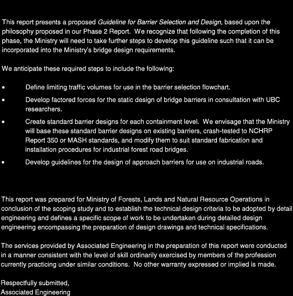
Phase III Guideline for Barrier Selection and Design
|
|
|
- Hilary Adams
- 5 years ago
- Views:
Transcription

1 R E P O R T P R O P O S A L AUGUST 2011 BRITISH COLUMBIA Ministry of Forests, Lands and Natural Resource Operations Phase III Guideline for Barrier Selection and Design
2
3 REPORT Table of Contents SECTION Table of Contents PAGE NO. i 1 Introduction 1 2 Barrier Selection 1 3 Barrier Design Pedestrian Railing 5 4 Approach Barrier Selection 5 5 Further Work 6 6 Closure 6 Appendix A - Sample Bridge Barrier Decision Flowchart i
4 (BLANK PAGE)
5 REPORT 1 Introduction Although the CAN/CSA-S6-06, Canadian Highway Bridge Design Code (CHBDC) is a primary reference for forest road bridge design, the bridge barrier design requirements do not directly relate to industrial forest road bridge barrier design. As a result, the Ministry of Forests, Lands and Natural Resource Operations (the Ministry) retained Associated Engineering (AE) to assist in the development of appropriate bridge barrier design guidelines, including specified design parameters, for Forest Service Road bridge barriers. In Phase 1 of this project, we reviewed existing literature regarding current practices for the design and installation of bridge barriers on low volume and forestry road bridges in North America. In Phase 2, we presented a proposed Barrier Selection and Design Philosophy, which we based on the previously completed literature review and current Ministry practices. In this phase, Phase 3, we present a proposed Guideline for Barrier Selection and Design, based upon the philosophy proposed in our Phase 2 Report. The work completed to date suggests that barrier selection and design comprises: Defining the level of containment required based on site-specific characteristics including traffic type (mix), traffic volume and speed, bridge width, road curvature and height of the bridge above ground/water. Selecting or designing an appropriate bridge barrier that will provide the desired level of containment. The following sections present a proposed methodology to facilitate the decision making and selection/design processes. 2 Barrier Selection To facilitate the selection of an appropriate barrier that provides sufficient containment, we recommend the development of a decision flowchart to determine to the required level of containment. We have included a draft decision flowchart based on discussions with the Ministry in Appendix A. The decision flowchart incorporates the following bridge and traffic characteristics: To account for traffic mix and volume, and the associated level of containment, we propose the following classifications: Type 1: The road is travelled exclusively by industrial vehicles operated by drivers familiar with driving conditions and safety protocols of the route. 1
6 Ministry of Forests, Lands and Natural Resource Operations Type 2: The road is predominantly travelled by industrial vehicles operated by drivers familiar with driving conditions and safety protocols of the route, with less than X 1 Vehicles per Day (VPD). Type 3: Although designated an industrial road, a significant portion of the traffic constitutes uncontrolled public traffic operated by people who may be unfamiliar with the driving conditions and safety protocols of the route, with less than Y 1 VPD. Type 4: The road is travelled primarily by uncontrolled public traffic mixed with industrial vehicles, and sees traffic volumes exceeding Y 1 VPD. To account for the height of the bridge above water we assumed that bridges with deck elevations more than 5.0 m above present water require a higher level of containment. This is consistent with the approach adopted by the BC MoTI and Ontario Ministry of Natural Resource Operations. To account for vehicle operating speeds, we assumed that bridges require a higher level of containment where the design speed exceeds set thresholds of 50 km/hr and 80 km/hr. To account for the increased angle of impact and possible increased road curvature associated with wider bridges, we assumed that a higher level of containment is required on bridges with deck widths that exceed set thresholds of 5.6 m and 8.0 m. Using these criteria, we recommended that the Ministry define the following three containment levels: Containment Level 1 (CL-1): This level of containment is suitable on bridges that display the flowing characteristics: Exclusively industrial traffic and minimal public traffic Relatively low height above water/hazard. Good vertical and horizontal alignment. No pedestrian traffic. Normal operating speeds Containment Level 2 (CL-2): This level of containment is suitable for bridges that display one or more of the following characteristics: Limited use by the public and pedestrians users who may be unfamiliar with the route and associated hazards. Significant height above water and/or near a significant hazard. Adverse geometry and / or visibility. Increased deck width. Increased operating speeds. 1 The Ministry to develop traffic volumes X and Y. 2
7 Report Phase III - Guideline for Barrier Selection and Design Containment Level 3 (CL-3): This level of containment is suitable for bridges that display on or more of the following characteristics: High level of public and / or pedestrian use (may provide access to recreation destinations, or rural communities, and may see a significant proportion of drivers who are unfamiliar with the driving conditions. Significant height above water. Adverse geometry and / or visibility. Increased deck width or multi-lane bridge. High operating speeds. 3 Barrier Design To ensure the provision of the minimum specified level of containment described in the previous section, we recommend that the Ministry mandate the use of pre-approved standard bridge barriers. Based on the proposed three levels of containment, we recommend that the Ministry adopt the following: Containment Level 1: Adopt the current standard bridge barriers including the top and side mounted timber barriers and the side mounted HSS and W-Beam barriers. We recommend that the FLRNO maintain the current bridge barrier height of 500 mm. Containment Level 2: Develop standard bridge barriers by modifying existing bridge barriers crash-tested to AASHTO MASH Test Level 1 (TL-1). We recommend that the Ministry adopt a minimum barrier height of 500 mm. Although lower than the 685 mm minimum height recommended by AASHTO LRFD 2010, this is similar to requirements mandated by the US Forest Service. Containment Level 3: Develop standard bridge barriers by modifying existing bridge barriers crash-tested to AASHTO MASH Test Level 2 (TL-2). Should the Ministry allow the development of alternative bridge barriers (i.e. bridge barriers not preapproved by the Ministry), we recommend that the Ministry adopt the following design and testing methodology: Require the static testing of barriers to verify the analytical predicted capacities and confirm that the load deformation behaviour is equivalent to the existing barriers. To allow for comparisons to be made with existing Ministry standard bridge barriers, we recommend that the static testing be completed using the methodology outlined in the Experimental Evaluation of Concrete Decks with Guard Rail Systems by Villiard, Dickof, Angers, Scheider, and Stiemer, April Require the static design of bridge barriers for the forces listed in Table 3-1. The standard 3
8 Ministry of Forests, Lands and Natural Resource Operations CL-1 timber curb has a static capacity ranging from kn, while the CL-2 HSS steel barrier has a capacity of approximately 60 kn. The 40 kn transverse load, FT, for CL-1, is intended to be an interpolation of the two levels of test results. Table 3-1 Proposed Barrier Design Criteria Factored Design Forces Containment Level CL-1 1,4 CL-2 2,4 CL-3 3,4 Transverse Load, F T, kn Longitudinal Load, F L, kn Vertical Load, F V, kn Deflection, mm Load Application Height, mm Minimum Barrier Height Note: 1. Minimum capacity of MNRO standard bridge barriers based on UBC testing documented in Experimental Evaluation of Concrete Decks with Guard Rail Systems, April The Ministry needs to confirm the magnitude of these forces through further study. 2. AASHTO LRFD specified design forces for TL-1 barrier. 3. AASHTO LRFD specified design forces for TL-2 barrier. 4. As discussed in Phase 1 of our Study, further investigation may allow for the reduction of these loads by 40% to account for dynamic amplification effects. 5. Based on load cylinder stroke in 2011 UBC static testing. 6. Height measured from travel surface, as shown in Figure 3-1. Figure 3-1 Minimum Bridge Barrier Height and Load Application Height 4
9 Report Phase III - Guideline for Barrier Selection and Design 3.1 Pedestrian Railing Where the Ministry expects significant pedestrian usage, we recommend the modification of the standard bridge barriers to include additional rails to achieve a minimum top-of-railing height of 1070 mm, the Code mandated minimum height for pedestrian railings. Notwithstanding, the Ministry should consider the effect that the higher rails may have on the ability of wide loads to cross the structure without damaging the pedestrian railing. 4 Approach Barrier Selection Anecdotal evidence suggests that the majority of railing collisions on resource road bridges occur because the vehicle lost control on the bridge approach rather than on the bridge deck. The primary purpose of approach barriers is to direct errant vehicles onto the bridge deck, preventing them from encountering hazards outside of the roadway. We recommend that the Ministry develop guidelines for determining whether approach barriers are required. These guidelines should prescribe a minimum approach barrier length based on a set of criteria, which could be selected from a flowchart, similar to that developed for selecting bridge barriers. We recommend that the flowchart account for approach curvature and embankment height. A suggested flowchart for approach barrier selection is presented in Figure 4-1 below. Adequate connection between the approach barriers and bridge barriers is critical redirecting an errant vehicle onto the bridge deck. As such, we recommend that the Ministry develop standard approach barrier connections for each of its standard bridge barriers. Figure 4-1 Approach Barrier Decision Flowchart 5
10
11 REPORT Appendix A - Sample Bridge Barrier Decision Flowchart A-1
12 (BLANK PAGE)
13 Bridge Barrier Decision Flowchart Traffic Mix - Mixture of industrial and public traffic. Type 1: Exclusively Industrial vehicle traffic < X VPD Predominantly industrial vehicle traffic < Y VPD Mostly industrial vehicle traffic, limited public mix Y VPD Primarily public traffic Bridge Deck Height - Measured from the top of the bridge deck to the top of the water or ground below. Bridge Deck height < 5.0 m above waterway or other hazard N Bridge Deck height < 10.0 m above waterway or other hazard N Y Y Design Speed Design Speed < 50 km/h N Design Speed < 80 km/h N Y Y Bridge Deck Width - Measured between inside of curbs. Bridge Deck Width < 5.6 m N Bridge Deck Width < 8.0 m N Y Y Containment Level Containment Level 1 (CL-1) Containment Level 2 (CL-2) Containment Level 3 (CL-3) Higher Standard Barrier Recommended Recommended Barrier type for the selected containment level. Current standard bridge barriers, including top & side-mounted timber barriers & side-mounted HSS & W-beam barriers. Minimum height = 500 mm above roadway. Standard barriers designed with force effects consistent with barriers crash-tested to AASHTO MASH TL-1. Minimum height = 500 mm above roadways, (AASHTO LRFD 2010, modified to account for reduced height) AASHTO MASH TL-2 barrier or better based on traffic volume and risk assessment Notes: 1.) The Ministry to develop traffic volumes X and Y. 2.) Where pedestrian use is expected, consider installing barrier-top rails to achieve a total height of 1070 mm. 3.) Where vertical grade exceeds the area-specific average (eg. > 4%), apply engineering judgement to determine whether a higher standard barrier is appropriate.