DRIVE-IN PALLET RACKING
|
|
|
- Laureen Mosley
- 5 years ago
- Views:
Transcription

1 DRIVE-IN PALLET RACKING Storage by accumulation : optimal use of available space


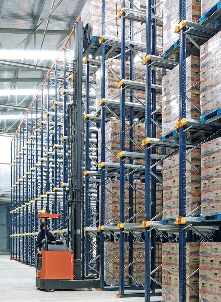
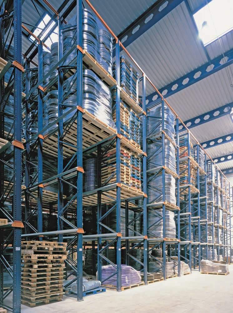
2 DRIVE-IN PALLET RACKING Designed for the storage of homogenous products Accommodates a large number of pallets for each SKU Better use of the available surface and height space than any other system This type of installation is made up of a set of racking units that form inner loading aisles, with support rails for the pallets. The forklift trucks enter these inner aisles with their load held higher than the level at which it is to be deposited. Each loading aisle has support rails on both sides. These are arranged on different levels and the pallets are placed on top. This racking system is made of extremely robust material, thus making it suitable for storing fully-loaded pallets. 2
3 3

4 The drive-in system can accommodate as many SKU s as there are loading aisles. The number of pallets will depend on the depth and height of the loading aisles. It is advisable to store products with the same SKU in each loading aisle, in order to avoid unnecessary pallet manoeuvres. The depth of each aisle will depend on the number of pallets per SKU, the space available and the length of time they will be stored. As shown in the following illustrations, the drive-in system has a greater storage capacity than the conventional pallet racking system. The illustrations show one facility with three different distributions and capacities. Conventional distribution Total area for atorage: 858m2 Capacity: 306 pallets per level Drive-in distribution Total area for storage: 855m2 Capacity: 522 pallets per level 4


5 Conventional pallet racking and drive-in systems are usually combined in one warehouse. The drive-in system is used for products with a faster turnover. Capacity: 383 pallets per level (200 pallets on drive-in system and 183 pallets on conventional pallet racking) 5


6 LOAD MANAGEMENT ON A DRIVE-IN SYSTEM Drive-in This is the most common way of managing loads in a drive-insystem. The racking units work like a warehouse depot. There is just one access aisle, from which loading and unloading are carried out in reverse order. A B C D Loading order: A, B, C, D Unloading order: D, C, B, A LIFO system - the first load IN is the last one OUT Drive-through In this case, the load is managed using the racking unit as a controlling warehouse, with two load access points, one on each side of the unit. With this system, it is possible to control production differences, for example between manufacture and dispatch, between production phase 1 and phase 2, or between production and loading bays. A B C D Loading order: A, B, C, D Unloading order: A, B, C, D FIFO system - the first load IN is the first one OUT 6
7 7


8 Forklift trucks The forklift trucks enter the storageaisles with their load held higher than the level at which it is to be deposited. Counterbalanced forklifts and standard reach trucks are the types used with drive-in systems. Unlike the conventional system, the pallets are handled perpendicular to their stringers. In drive-in pallet racking, the forklift truck deposits the pallet by resting the stringers on the support rails. An extreme amount of pressure is exerted on the stringers, so the pallets used must be in very good condition. The following illustrations show the correct way to place the pallets. Pallets can only be placed the other way around if they are strong and rigid enough, and if the weight of the load allows it. If the load overhangs the pallet, dimensions A and B (the pallet measurements) may be different to A and B (the load measurements), which will influence the dimensions of the racking and supports, as shown in the pages relating to Clearances section. YES NO 8

.")
9 The forklift trucks travel along the insides of the storage aisles so the necessary margins must be calculated in order to work safely. Certain measurements must be taken into account when designing an installation: A. Total width of the forklift truck. There must be a minimum clearance between the forklift truck and the vertical elements of the racking units of 75 mm on each side. Dimension X, the distance between the uprights, must include this. B. Operator s protection structure. A minimum clearance of 50 mm to the support rails is needed (dimension Y). C and D Height of the base and protection of the forklift truck. Dimension Z and dimension Y must be cleared comfortably. E. Maximum elevation height. Must be at least 200 mm greater than dimension W. 9
 Calculation criteria Mecalux uses a powerful calculation program that implements the most important aspects of the above standards and")

10 BASIS FOR CALCULATION Guidelines and recommendations Mecalux calculates the compact racking units following the main criteria of: Eurocode 3 FEM Directive (Design of Drive-in Pallet Racking) Calculation criteria Mecalux uses a powerful calculation program that implements the most important aspects of the above standards and recommendations, such as: Safety coefficients for both increasing loads and reducing material Specific load situations for limit conditions and service conditions Minimum pallet support on the 20 mm rail when the unit load is moved, considering the load condition that causes most deformity to the shelving Second order calculation Modelled structure with global and local imperfections. 10

 11.")
11 BASIC COMPONENTS 1. Frame 2. Drive-in beam 3. Bracket 4. GP-7 rail 5. C-rail 6. Upright footplate 7. Levelling plates 8. Anchor bolts 9. Bracing set (Construction system 1) 10. Upper cross bracing (Construction system 2) 11. Guide rail (optional) 16
.")
12 Height The minimum height measurements required are as follows: F: height of the lower and intermediate levels = height of thepallets mm G: height of the upper level = height of the pallets mm H: total height = at least, the sum of all the levels. Dimensions F, G and H must always be multiples of 50 mm (figure 4). Depth The minimum depth measurements to consider are the following: X: the total depth of all the pallets (including the measurement of the load if it protrudes) plus a clearance for positioning, which varies from 35 to 50 mm per pallet, depending on the number of pallets (the more the pallets there are the less the clearance required) (figure 5). 19


13 Construction system with C-rails This system is installed when the pallets used have different frontal measurements, and for very large storage units requiring greater support clearances. With C-rails it is not possible to auto-centralise the different pallets that may be stored in an aisle. The system also means that the operators have to be more careful when manoeuvring forklifts (figure 6). The pallets must be analysed before defining the support measurements. The following illustrations show solutions for storing 1300 mm and 1200 mm wide pallets, where the load does not overhang the pallet in either case (figures 7 and 8). 20


14 Guided, with single profile The single-profile solution is sufficient when it is only necessary to guide the pallets. The measurements between guides with LPN50 profiles and standard protectors are as follows: Dimensions of the aisle with standard guides and protectors - mm X Y Another guiding system that can be used is with U-shaped profiles placed at the bottom of the racking uprights and held to the floor using the same anchor bolts. This guiding system allows for greater separation between guides for wide-chassis forklift trucks, without the need for wider aisles. Front protectors can also be installed. Specific analysis is required before a particular system is chosen. Guided, with double profile The double-profile solution is more common when the machine is guided with wheels and the dimensions and shocks they transmit make it essential. 23


15 HEAD OFFICE BULGARIA STAMH Ltd Sofia 1612, 126 Tzar Boris III Blvd, tel , office@stamh.bg BRANCHES AUSTRIA STAMH GmbH Vienna 1140, 395/15 Linzer Str, tel , office@stamh.com SERBIA STAMH doo Novi Sad 21000, 18 Augusta Cesarca, tel , office@stamh.rs