W E C O N V E Y Q U A L I T Y Pan Conveyors
|
|
|
- Asher Holland
- 5 years ago
- Views:
Transcription

1 W E C O N V E Y Q U A L I T Y Pan Conveyors


2 CONTENTS 2 AUMUND Pan Conveyors 4 Pan Conveyor with Deep Drawn Pans type KZB 8 Pan Conveyor with Deep Drawn Pans and Baffles type KZB-Q 10 Pan Conveyor with Buckets type BZB 14 Pivoting Pan Conveyor type SPB 18 Reversible Deep-Drawn Pan Conveyor type KZB-R 19 Silo Discharge type SAK 20 Components Chain Technology 21 Accessories 22 Conversions and Refurbishments 23 After-Sales Services AUMUND Pan Conveyors Technology with proven quality, strength and reliability AUMUND Pan Conveyors are designed to suit efficiency driven process technologies and to ensure system performance. At AUMUND we know that trouble-free operation of the conveying equipment is vital for the productivity and profitability of the whole plant. Keeping in mind this objective we are committed to our high quality standards which are reflected in the exceptional service life of the AUMUND Pan Conveyor. Our focus is to satisfy specific requirements with creative, cost-effective solutions for the transport of the whole range of bulk materials in cement production from limestone, cement and additives to hot and abrasive cement clinker. With 85 years in industrial engineering of conveying equipment we also assist customers worldwide with conceptual layouts and configuration. Our primary goal is to identify and provide the most efficient and economic conveying routes. For the whole range of bulk materials in cement production Engineered to suit plant and operator needs High quality standards Outstanding service life Efficient and economic conveying routes 2
3 3

4 Conveying route with Pan Conveyor KZB Pan Conveyor with Deep Drawn Pans type KZB The Pan Conveyor with deep drawn pans type KZB is designed to suit slopes matching the angle of repose of the conveyed bulk material. For clinker handling the Pan Conveyor type KZB suits conveying routes with an inclination up to 30. This Pan Conveyor type is the ideal direct connection between cooler and clinker stock especially for applications with grate coolers. The design allows the Pan Conveyor to be arranged underneath the whole cooler length and to collect the fines from the dust collecting hoppers same as the clinker from the crusher. Installed underneath the clinker stock in combination with the AUMUND Silo Discharge Gate, the Pan Conveyor with deep drawn pans type KZB allows for dust-controlled clinker reclaim. Designed for conveying routes with up to 30 inclination Conveying heights exceeding 75 m Conveying capacities exceeding 1,000 t/h Chains with 290 to 3,000 kn breaking load per strand 4


5 Deep Drawn Pan Conveyor under Clinker Cooler Features Accepts temperatures to 700 C Designed as a modular structure with standard components Profiled pans for high rigidity Minimum spillage Highly wear resistant chains with high yield strength High quality standards on all components Benefits Efficient and reliable operation Reduced installation time Low operating costs Minimum and easy maintenance Low power consumption Low overall investment cost Outstanding service life 5


6 Pan Conveyor with Deep Drawn Pans type KZB Pan Conveyor type KZB - Detail 6

7 Deep-Drawn Pan Conveyor - Detail The characteristic profile of the pans with their contact-free overlapping offers high rigidity with large pan widths and a closed surface in the return stations. Stiffeners pressed into the side plates combined with a sealing edge of special design provide the tight fitting to avoid spillage. The range of AUMUND conveyor chains covers a large range of applications, from small capacities and horizontal conveying routes to high capacities and lifts. The chain - for single or double strand application is chosen to suit the actual traction force while the roller size is chosen in accordance with the weight of the pan conveyor itself and the conveyed material. The drive units feature bevel spur gears either foot mounted with flexible coupling or shaft-mounted. For inclined conveying, the gear box is fitted with a back stop or, alterna tively, a flexible coupling with brake is arranged between gear box and motor. The coupling between motor and gear box can be hydraulic or flexible for soft start-up. Frequency converters adapt the conveying speed to the actual conveying capacity. Conveying Capacities - Pan Conveyor type KZB The capacities indicated correspond to a brimfull filling (water filling) = 100 %. Capacity reduction factor subject to angle of inclination. Conveyor section type KZB Theoretical conveying capacity m³/h Width Side wall Conveying speed m/s height mm mm , , , , , , , , , , , , , , , , , , , , , , , , , , , , , ,083 2, , , , ,053 2, ,021 1,191 2, , , , ,148 2, ,114 1,300 7


8 Pan Conveyor KZB-Q connecting cooler and silo Pan Conveyor with Deep Drawn Pans and Baffles type KZB-Q Designed for conveying routes with up to 45 inclination Conveying heights to 78 m Conveying capacities to 700 t/h Chains with 290 to 3,000 kn breaking load per strand KZB-Q inclined at 45 degrees 8

9 For slopes exceeding 30 degrees retainer baffles are fitted to the deep drawn pans. These baffles are welded to the bottom plate and held in a loose fitting by cams which are pressed into the upper part of the side boards. The loose fitting allows the baffles to bend in case foreign bodies get onto the conveyor. All further parts of the KZB-Q are interchangeable with the KZB. These standardized components constitute the AUMUND modular system for easy field assembly and interchange - ability, an important asset for spare parts administration. Deep Drawn Pans with Baffles Conveying Capacities - Pan Conveyor type KZB-Q The capacities indicated correspond to a brimfull filling (water filling) = 100 %. Capacity reduction factor subject to angle of inclination. Conveyor section type KZB-Q Theoretical conveying capacity m³/h Width Side wall Conveyor speed m/s height mm mm , , , , , , , , , , , , , , , , , , , , , , , , , , , ,083 2, , , ,053 2, ,021 1,191 2, , , ,148 2, ,114 1,300 9

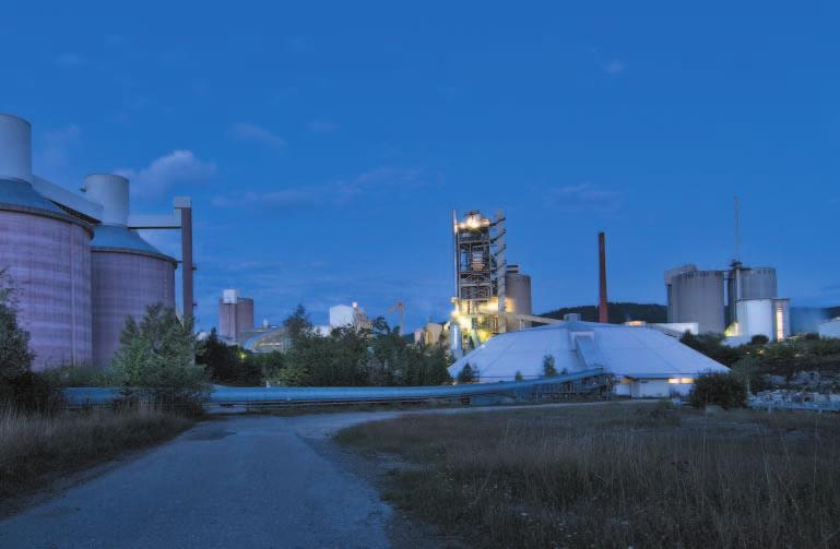
10 Feeding of covered stockpile Pan Conveyor with Buckets type BZB Designed for conveying routes with up to 60 inclination Conveying heights to 96 m Conveying capacities to 500 t/h Chains with 290 to 3,000 kn breaking load per strand Wherever conveying of clinker with a high content of fines is required, the Bucket Conveyor type BZB is the most appropriate choice. The bucket design with either forward or backward overlapping is designed to suit this particular application and minimizes spillage and cleaning. Designed for conveying at an inclination up to 60 degrees, the Bucket Conveyor fits into layouts com bining high elevation with restricted space. The narrow curve radius is a further feature to suit these applications where only limited space is available, a considerable advantage for modernization projects or conversion in existing plants. Uniform bucket filling and even material distribution over the whole bucket width is ensured by expert planning of the feed chute system - a pre-requisite for trouble-free operation with minimum dust generation. 10


11 Bucket Apron Conveyor Feeding of mill hoppers 11

12 12 Clinker Transport with Conveyor type BZB

13 Conveying Capacities - Bucket Conveyor type BZB The capacities indicated correspond to a brimfull filling (water filling) = 100 %. Capacity reduction factor subject to angle of inclination. Conveyor section Theoretical conveying capacity m³/h type BZB Width Side wall Conveyor speed m/s height mm mm , , , Bucket Apron Conveyor type BZB Detail 1, , , , , , The bucket - standard widths to 1,600 mm - feature a built-in stiffener for high solidity. Depending on the case of application the overlapping of the buckets is either forward or backward. With the tight bucket arrangement the BZB meets the criteria for proper feeding with minimum spillage. The modular system also applies for the AUMUND Bucket Conveyor, ensuring interchangeability and combination with components like those used with the Deep Drawn Pan Conveyor. Features Ideal for conveying of clinker with a high content of fines Narrow curve radius, down to 10 m Expert design of the feed chute system Designed as a modular structure with standard components Minimum spillage Highly wear resistant chains with high yield strength High quality standards on all components Benefits Efficient and reliable operation Suits applications with limited space Low operating costs Minimum and easy maintenance Outstanding service life 13

14 Feeding two silos in line Pivoting Pan Conveyor type SPB For bulk material distribution into a series of silos or hoppers, the Pivoting Pan Conveyor offers the most versatile arrangements. The Pivoting Pan Conveyor ensures PLC controlled multiple distribution of various materials with just one conveyor. Pan reversing system for simultaneous conveying on the upper and lower run Intermediate discharge stations placed at any given position Upper and lower run feeding Specific feeding and discharge features Feeding onto the upper run is performed with a standard feed chute whilst a two-way chute leads the bulk material to the lower run. Equipped with an overflow system the feed chutes also ensure direct discharge of the bulk material into the silo or hopper. Intermediate discharge stations may be positioned where required and permit remote controlled switching from one discharge station to the other. Bulk material directed onto the upper run can subsequently be transferred to the lower run through an intermediate discharge station located on the upper run. 14


15 Feed chute Upper run Feed chute Lower run Drive station Discharge station Upper run Discharge station Lower run Take-up station Overflow Upper and lower run feeding and discharge The material may then be distributed into clinker silos or mill hoppers through discharge stations on the lower run. Simultaneous conveying on the upper and the lower run is a further alternative. A hopper can thus be loaded with cement clinker by way of the lower run whilst for example gypsum is conveyed on the upper run. Mill hopper feeding 15


16 Bulk Material Distribution into Storage Halls Drive station Feeding lower run Discharge carriage Take-up station Drive station Feeding upper run Drive station Feed chute with emergency overflow Direction of travel for mobile discharge carriage Take-up station Bulk Material Distribution into a Series of Silos Drive station Feeding lower run Take-up station Drive station Feeding upper run Take-up station Drive station Feed chute with emergency overflow Discha station Bulk Material Distribution into Silos and Storage Hall Drive station Feeding upper run Discharge carriage Take-up station Drive station Feeding Lower run 1 Feeding Lower run 2 16


17 Discharge carriage Take-up station Conveying capacity - Pivoting Pan Conveyor type SPB The capacities indicated correspond to a brimfull filling (water filling) =100 % Conveyor section Theoretical conveying capacity m 3 /h Pan width Side wall height Conveyor speed m /s Filling rate limit Plw mm mm % % % % % % 1, % 1, % 1, % 1, % 1, % 1, % 1, % 1, % Theoretical rate limit Filling rate limit rge Take-up station with forced discharge Feeding of long clinker storage halls requires continuous shifting of the discharge point. A mobile discharge carriage which can be moved to any given position above the hall is used with this particular application. The clinker is continuously distributed over the whole travel length of the carriage. Sensors on the conveyor supports monitor the posi tion of the travelling carriage. Level indicators control automatic shifting of the carriage as soon as a maximum filling level is reached inside the storage hall. Feeding upper run Discharge carriage Take-up station Automated feeding of clinker silos, mill hoppers and clinker halls Simultaneous conveying of different bulk materials PLC-controlled operation Automated material distribution controlled by level sensors Customized layout and planning Standardized components 17


18 Clinker Silos 2 x 60,000 t Reversible Deep-Drawn Pan Conveyor type KZB-R For applications where conveying in both direc tions is required, the Deep Drawn Pan Conveyor may be converted into a reversible conveyor. Alternate feeding of two silos with just one conveyor is made possible by simply changing the conveying direction. This conveyor of special design suits horizontal arrangements. The illustration shows a plant where feeding of two clinker silos is performed with one Bucket Elevator and one Reversible Conveyor. The Bucket Elevator unloads the clinker in the centre of the subsequent Reversible Conveyor which then feeds the clinker to either one of the silos. Operation of the Reversible Conveyor is PLC controlled from the central control room ensuring that the pans are cleared before shifting from one direction to reverse conveying. To achieve this type of operation the pans are arranged such that the pan overlapping always points into the chosen conveying direction. If required with a long centre distance, both conveyor ends are fitted with a drive unit. Alternate feeding of two silos with one conveyor Conveying in both directions by simply shifting to reverse conveying Clinker silo feeding with reversible pan conveyor Reversible pan conveyor - functional principle 18

19 Silo Discharge with Remote Control Silo Discharge type SAK For clinker silo discharge with low dust emission, for proportional addition of low-burnt or imported clinker AUMUND s product range includes the Gravity Discharge Unit operating in combination with the Deep Drawn Pan Conveyor. The height of the material layer on the pan conveyor determines the discharge rate and the feeding capacity onto the subsequent conveying equipment. Preset during commissioning, it is adjusted to the specific requirements of the plant. With its built-in motorized shell gate the Gravity Discharge Unit prevents the clinker from falling in an uncontrolled manner onto the pan con veyor. It reclaims the clinker at low speed and minimizes dust generation. Where adequate, the Gravity Discharge Unit may also be manually operated. For uniform discharge of the stored volume, a multitude of motorized Gravity Discharge Units are installed underneath the clinker silo. Switching between discharge points is made by remote control assisted by ultrasonic sensors detecting lack of clinker on the conveyor. 19


20 Components AUMUND Pan Conveyors feature standardized components forming part of the modular system. Components of different pan conveyor types are interchangeable, a major advantage for spare parts management. Bogie-type rails ranging from size S14 to S30, chosen to suit the pan conveyor size Roller guide-rails in the curve area Standard roller design with tempered running surface and multiple sealing and life lubrication Drive and tail shaft sprockets with exchangeable toothed segments for easy replacement Sprockets with double tooth pitch meshing with the sprocket teeth only after each second turn for increase of lifetime Chains with breaking loads ranging from 290 kn to 3,000 kn Type for conveyor type breaking load kn AU KZB BAU BZB 290 AU KZB BAU BZB 510 AU KZB BAU BZB 700 AU KZB BAU BZB 900 AU KZB BAU BZB 1,200 AU KZB BAU BZB 1,900 AU KZB BAU BZB 2,350 AU KZB BAU BZB 3,000 Chain Technology High precision manufacturing technology Special, wear-resistant steel High yield strength AUMUND chains for Pan Conveyors are fabricated from special steel suitable for accurate laser cutting. The high precision manufacturing technology combines high yield strength with perfect distribution of forces. The chain features a divided chain locking link, so field assembly is simplified. Chain pitch 250mm 20


21 Accessories Two way distribution chute Three way distribution chute Motorized flat gate Maintenance trolley for conveyor bridge Remote control of downstream conveying directions is performed with the AUMUND two or three-way distribution chute. The chutes are fitted with shell gates actuated either by a gear motor or a hydraulic / pneumatic cylinder. Casing and shell gates are of wear-resistant design for a long service life. Motorized flat gates of sturdy design complete the range of accessory equipment for material distribution. In addition, AUMUND offers maintenance trolleys with rack and pinion drive to be installed inside conveyor bridges for transportation of heavy tools, oil bins or equipment components to the top of high clinker silos. The maintenance trolleys are designed to suit any angle of inclination. The range of accessory equipment is completed by truck and ship loading systems with low dust generation and electronic control for easy loading operations. 21


22 Installation of new bucket strand Conversions and Refurbishments Upgrading of existing plant components Targeting increased efficiency Higher output Improved availability With our expert team of engineers planning selective modernisation measures, we pay special attention to the upgrading of existing plant components, targeting increased efficiency, higher output rates and improved availability. Upgrading of your materials handling and storage equipment to state-of-the-art technology is achieved through a tailor-made refurbishment process under optimum utilisation of time and budget. Most of the existing components are re-used in the refurbishment process to save cost. Engineered conversions and refurbishments for increased efficiency and output are performed on AUMUND equipment as well as on the equipment of other manufacturers. Pre-assembly of chain strands 22

23 After-Sales Services Customer Proximity around the World At AUMUND, service does not end at the sale of the equipment. It's the beginning of a long-term partnership. AUMUND offers you a full range of services from commissioning to the delivery of quality spare and wear parts, to customized preventive maintenance programs and equipment upgrading. The benefits for you: Maximum equipment efficiency at lower operating cost. Commissioning and Field Service Today, presence on the spot is an absolute must. Therefore, our commissioning and service engineers operate from support centers on all continents to guarantee immediate and competent support. Spare and Wear Parts A comprehensive range of genuine spare parts is available for our entire product range from stocks in Germany, Hong Kong and the USA. Our product specialists provide assistance and respond instantly. Retrofits Aged and worn equipment? Capacity increase needed? Too high operating cost? Aumund just as new retrofits are economical and tailor-made solutions for improving your existing equipment at reasonable cost. Preventive Maintenance Knowing beforehand that service will be needed allows you to schedule downtime and save money with timely repairs. Repairs or retrofits can be accurately anticipated allowing for the downtime to be at the most convenient times and at the lowest possible cost. THE AUMUND GROUP GERMANY AUMUND Fördertechnik GmbH Saalhoffer Str Rheinberg Phone: Fax: aumund@aumund.de AUMUND Logistic GmbH Saalhoffer Str Rheinberg Phone: Fax: logistic@aumund.de SCHADE Lagertechnik GmbH Dorstener Straße Herne Phone: Fax: info@schade-lagertechnik.de GREAT BRITAIN B&W Mechanical Handling Ltd. Gemini House Cambridgeshire Business Park, 1 Bartholomew`s Walk Ely, Cambridgeshire CB7 4EA Phone: Fax: sales@bwmech.co.uk INDIA AUMUND Engineering Private Ltd. 2nd Floor, Lakshmi Neela Rite Choice Chambers 9, Bazulla Road, T. Nagar Chennai Phone: Fax: aumund@vsnl.com RUSSIA AUMUND Representative Office Moscow German-Russian House, Office 44 ul. Malaya Pirogovskaya Moscow / Russia Phone: Fax: info@aumund.ru HONG KONG SAR AUMUND Asia (H.K.) Limited Unit 3B & 5, 30/F, 148 Electric Road, North Point Hong Kong Phone: Fax: info@aumund-asia.com DUBAI U.A.E. AUMUND Fördertechnik GmbH Representative Office P.O. Box Dubai, UAE Phone: catalina@aumund.com THE NETHERLANDS AUMUND Holding B.V. Wilhelminapark EE Venlo Phone: Fax: info@aumund-holding.nl SWITZERLAND AUMUND AG Arther Str Zug Phone: Fax: info@aumund.ch FRANCE AUMUND France S.A.R.L. 43, rue de Trévise F Paris Phone: Fax: aumund@aumund.fr BRAZIL AUMUND Ltda. Av. Eng. Luis Carlos Berrini, andar - Conj São Paulo / SP, Brazil Phone: Fax: aumund@aumund.com.br USA AUMUND Corporation 1825 Barrett Lakes Boulevard Barrett Lakes Center II Suite 520 Kennesaw, GA Phone: Fax: sales@aumundusa.com P.R. CHINA AUMUND Machinery Trading (Beijing) Co. Ltd. Rm. 7-8, 22-F, East Ocean Centre No. 24 Jianguomenwai Avenue Chaoyang District Beijing Phone: / 14 Fax: aumund@aumund.cn 23

24 W E C O N V E Y Q U A L I T Y AUMUND Headquarters in Rheinberg, Germany Your partner for all requirements regarding material handling and storage. We design, engineer, manufacture, erect and service reliable equipment. Reputation and competence proven by more than 10,000 installations in over 100 countries. AUMUND Foerdertechnik GmbH. Saalhoffer Str Rheinberg (Germany) Tel.: +49(0) Fax: +49(0) aumund@aumund.de GB Technical data subject to change without notice A-GB-02-V/12-FE By AUMUND Foerdertechnik GmbH. All rights reserved.