Two Test Level 4 Bridge Railing and Transition Systems for Transverse Timber Deck Bridges
|
|
|
- Alan McKinney
- 5 years ago
- Views:
Transcription
1 University of Nebraska - Lincoln DigitalCommons@University of Nebraska - Lincoln Civil Engineering Faculty Publications Civil Engineering 2000 Two Test Level 4 Bridge Railing and Transition Systems for Transverse Timber Deck Bridges Ronald K. Faller University of Nebraska - Lincoln, rfaller1@unl.edu Michael A. Ritter USDA Forest Service Barry Thomas Rosson University of Nebraska - Lincoln Michael D. Fowler Sheila R. Duwadi Federal Highway Administration Follow this and additional works at: Faller, Ronald K.; Ritter, Michael A.; Rosson, Barry Thomas; Fowler, Michael D.; and Duwadi, Sheila R., "Two Test Level 4 Bridge Railing and Transition Systems for Transverse Timber Deck Bridges" (2000). Civil Engineering Faculty Publications This Article is brought to you for free and open access by the Civil Engineering at DigitalCommons@University of Nebraska - Lincoln. It has been accepted for inclusion in Civil Engineering Faculty Publications by an authorized administrator of DigitalCommons@University of Nebraska - Lincoln.
2 334 Transportation Research Record 1696 Paper No. 5B0110 Two Test Level 4 Bridge Railing and Transition Systems for Transverse Timber Deck Bridges Ronald K. Faller, Michael A. Ritter, Barry T. Rosson, Michael D. Fowler, and Sheila R. Duwadi The Midwest Roadside Safety Facility, in cooperation with the Forest Products Laboratory, which is part of the U.S. Department of Agriculture s Forest Service, and FHWA, designed two bridge railing and approach guardrail transition systems for use on bridges with transverse glue-laminated timber decks. The bridge raging and transition systems were developed and crash tested for use on higher-service-level roadways and evaluated according to the Test Level 4 safety performance criteria presented in NCHRP Report 350: Recommended Procedures for the Safety Performance Evaluation of Highway Features. The first railing system was constructed with glulam timber components, whereas the second railing system was configured with steel hardware. Eight full-scale crash tests were performed, and the bridge railing and transition systems were acceptable according to current safety standards. Over the past 30 years, numerous bridge railing systems have been developed and evaluated according to established vehicular crashtesting standards. Most of the bridge railings previously crash tested have consisted of concrete, steel, and aluminum railings attached to concrete bridge decks. It is well known that a growing number of timber bridges with transverse and longitudinal timber decks are being constructed throughout the country. Therefore, the demand for crashworthy railing systems has become more evident with the increasing use of timber decks located on secondary highways, county roads, and local roads. Over the past 10 years, several crash-worthy bridge railing systems have been developed for use on longitudinal timber decks. In addition, these railing systems were developed for multiple service levels that ranged from low-speed, low-volume roads to higher-service-level roadways. However, little research has been conducted in the development of crash-worthy railing systems for bridges with transverse timber decks, and those that have been developed are for use on low-to-medium service-level roadways. For timber to be a viable and economical alternative in the construction of transverse timber decks, additional railing systems must be developed and crash tested for timber decks that are located on higher-service-level roadways for which no railing systems existed before. Because of the need to develop bridge railing systems for this higher service level, the Midwest Roadside Safety Facility (MwRSF), R. K. Faller, Midwest Roadside Safety Facility University of Nebraska-Lincoln, 1901 Y Street, Building C, Lincoln, NE M. A. Ritter, USDA Forest Service, Forest Products Laboratory, One Gifford Pinchot Drive. Madison, WI B. T. Rosson, Department of Civil Engineering, University of Nebraska- Lincoln, W348 Nebraska Hall, Lincoln, NE M. D. Fowler, MK Centennial, West 64th Avenue, P O. Drawer 1307, Arvada, CO S. R. Duwadi, Turner-Fairbank Highway Research Center, Federal Highway Administration, 6300 Georgetown Pike, McLean, VA in cooperation with the Forest Products Laboratory (FPL), which is a part of the U.S. Department of Agriculture s Forest Service, and FHWA, undertook the task of developing two higher-service-level bridge railings and approach guardrail transitions. RESEARCH OBJECTIVES The primary objective of this research project was to develop and evaluate two bridge railings and approach guardrail transitions for use with transverse glue-laminated (glulam) timber deck bridges that were located on higher-service-level roadways. The bridge railing and transition systems were developed to meet Test Level 4 (TL- 4) evaluation criteria that are described in NCHRP Report 350: Recommended Procedures for the Safety Performance Evaluation of Highway Features (1). The first bridge railing, referred to as System No. 1, was a wood system that was constructed with an upper rail, a lower curb rail. scupper blocks, posts, and blockouts. all of which were manufactured from glulam timber. Photographs of the railing system of the wood bridge and the attached approach guardrail transition are shown in Figure 1. The second bridge railing, referred to as System No. 2, was a steel system that was constructed with a thrie-beam rail. an upper structural tube rail, and wide flange posts and blockouts. Photographs of the steel bridge railing system and the attached approach guardrail transition are provided in Figure 2. Another objective of the research project was to determine the actual forces imparted to the key components of the bridge railing systems. Knowledge of these force levels would allow researchers and engineers to make minor modifications to the crash-tested designs without additional full-scale crash testing and would provide insight into the design of future systems. RESEARCH PLAN The research objectives were accomplished with the successful completion of several tasks. First. a literature search was performed to review the previously developed, high-performance-level bridge railing systems, as well as to review bridge railings that were developed for timber deck bridges. -L-he review was deemed necessary because it was envisioned that the two new bridge railing designs would likely use technologies and design details from existing crash-worthy railing systems. Second, bridge railing concepts were prepared so that an analysis and design phase could be performed on all structural members and connections,
![Faller et al. Paper No. 5B0110 335 FIGURE 1 System No. 1: glulam rail with curb bridge railing [top] and thrie beam with curb transition [bottom].](/docs-images/86/93185492/images/3-0.jpg "Subsequently, computer simulation modeling was conducted by using BARRIER VII to aid in the analysis and design of the bridge railing and approach")
 static stiffness properties for use in")


 were performed by using ¾-ton pickup trucks")


.")

3 Faller et al. Paper No. 5B FIGURE 1 System No. 1: glulam rail with curb bridge railing [top] and thrie beam with curb transition [bottom]. Subsequently, computer simulation modeling was conducted by using BARRIER VII to aid in the analysis and design of the bridge railing and approach guardrail transition systems (2). For the wood system, static component testing was then performed on selected bridge components to obtain (a) static stiffness properties for use in the calibration of the computer simulation modeling and (b) calibration factors for instrumentation sensors that were located in strategically placed structural components. Additional instrumentation was placed on the bridge railing systems to help determine the actual dynamic loads imparted into the bridge railing and deck systems. The researchers deemed that the dynamic load information was necessary because additional economy could be provided with the downsizing of specific structural components. Next. eight full-scale vehicle crash tests (two crash tests on each bridge railing and transition system) were performed by using ¾-ton pickup trucks and single-unit trucks. Test results were analyzed, evaluated. and documented. Conclusions and recommendations that pertained to the safety performance of each bridge railing and transition system were then made. BRIDGE RAILING HISTORY The primary purpose of a bridge railing is to safely contain errant vehicles and prevent them from falling off the bridge. Therefore, railings must be designed to withstand the force of a striking vehicle without endangering its occupants. In designing railing systems for highway bridges, engineers have traditionally assumed that vehicle impact forces can be approximated by equivalent static loads that are applied to railing elements. Until recently. criteria presented in AASHTO s Standard Specifications for Highway Bridges (3) required that bridge railings be designed to resist an outward transverse static load of 44.5 kn. Despite the widespread use of design requirements that is primarily based on static load criteria, the need for more appropriate criteria that covers full-scale vehicle crash tests has long been recognized. The first set of U.S. guidelines for full-scale vehicle crash tests was published in 1962 (4). In 1981, NCHRP Report 230: Recommended Procedures for the Safety Performance Evaluation of Highway Appurtenances was published (5). This comprehensive report provided recommendations that were relative to crash testing and an evaluation of longitudinal barriers. It also served as the basis for requirements for future bridge rail crash testing. The first recognition of full-scale crash tests in a national bridge specification was in 1989 after AASHTO publishsd Guide Specifications for Bridge Railings (6). Thus specification presents recommendations for the development, testing. and use of crash-tested bridge railings and refers extensively to NCHRP Report 230 for crash-test procedures and requirements. For this specification, recommended requirements for rail tests were based on three performance levels: Performance Level 1 (PL-1), PL-2, and PL-3. PL-1 requirements represent the weakest system, and PL-3 represents the strongest system. The recently published NCHRP Report 350 identifies six test
![336 Paper No. 5B0110 Transportation Research Record 1696 FIGURE 2 System No. 2: steel thrie beam with tube bridge railing [top] and thrie beam with tube transition [bottom].](/docs-images/86/93185492/images/4-5.jpg "levels for evaluating longitudinal barriers-test Level 1 (TL-1) through TL-6.")


, were also provided for bridge railings as a replacement for the 44.5-kN equivalent static load procedures.")

4 336 Paper No. 5B0110 Transportation Research Record 1696 FIGURE 2 System No. 2: steel thrie beam with tube bridge railing [top] and thrie beam with tube transition [bottom]. levels for evaluating longitudinal barriers-test Level 1 (TL-1) through TL-6. Although this document does not include objective criteria for relating a test level to a specific roadway type, the lower test levels are generally intended for use on lower-service-level roadways and on certain types of work zones, whereas the higher test levels are intended for use on higher-service-level roadways. In 1994, AASHTO published the AASHTO LRFD Bridge Design Specifications (7) as an update to the Standard Specifications for Highway Bridges (3) and to the Guide Specifications for Bridge Railings (6). For crash testing bridge railings, three performance levels were provided. and guidelines followed procedures that were presented in both the AASHTO Guide Specifications for Bridge Railings and NCHRP Report 350. Yield line and inelastic analysis and design procedures. as originally developed by Hirsch (8), were also provided for bridge railings as a replacement for the 44.5-kN equivalent static load procedures. Emphasis on the use of crash-tested rails for new federally funded projects has significantly increased the role of full-scale crash tests as a means of evaluating railing performance. Recently, FHWA officially adopted NCHRP Report 350 as a replacement for NCHRP Report 230 and has strongly suggested that AASHTO also adopt the test-level definitions presented in NCHRP Report 350. thus making crash-tested railings mandatory for most bridges. Most highways on which wood bridges are installed will require railings that meet the NCHRP Report 350 requirements for TL-1 through TL-4. As of August 1986, 22 bridge rails had been successfully crash tested in accordance with the guidelines specified in NCHRP Report 230 and approved for use in federal aid projects by FHWA (9 ). By August 1990, 25 additional bridge rails had been successfully crash tested in accordance with the requirements of AASHTO s Guide Specifications for Bridge Railings and also approved by FHWA for use in federal aid projects (10). Of these crash-tested railings, 46 were used on concrete bridge decks. and only one was used on a wood deck (11). During the 1990s, two other research programs led to the development of crash-worthy railing systems for timber deck bridges. The first program. a collaborative effort between MwRSF, FPL, and FHWA engineers, resulted in the development of nine railing systems for longitudinal timber deck bridges (12-17). Simultaneously with the MwRSF research program, researchers at West Virginia University conducted a research effort to develop three AASHTO PL-1 railing systems for transverse wood decks (18). TEST REQUIREMENTS AND EVALUATION CRITERIA According to the TL-4 criteria presented in NCHRP Report 350, longitudinal barriers must be subjected to three full-scale vehicle crash tests: (a) a small car weighing 820 kg colliding at a speed of 100 km/h
5 Faller et al Paper No. 5B and at an angle of 20 degrees, (b) a pickup truck weighing 2000 kg colliding at a speed of 100 km/h and at an angle of 25 degrees, and (c) a single-unit truck weighing 8000 kg colliding at a speed of 80 km/h and at an angle of 15 degrees. For this research project, crash tests were performed by using only the pickup truck and single-unit truck impact conditions. Although the small car test is used to evaluate the overall performance of the length-of-need section and to assess occupant-risk problems that arise from snagging or overturning the vehicle, it was deemed unnecessary for several reasons. First, during the design of both barrier systems, special attention was given to prevent geometric incompatibilities that would cause the small car tests to fail as a result of excessive snagging or overturning. Second, the structural adequacy of higher-service-level barrier systems is not a concern for the small car test because of the relatively minor impact severity as compared with the impact severity for the pickup truck and the single-unit truck impact conditions. The impact severity for the pickup truck test is about 270 percent greater than the impact severity provided by the small car test. Third, a small car crash test was successfully conducted on a similar wood bridge railing system by the Southwest Research Institute (11). Finally, thrie-beam barriers struck by small cars have been shown to meet safety performance standards and to be essentially rigid (19-21), with no significant potential for occupant-risk problems that arise from snagging or overturning. For these reasons, the small car crash test was considered unnecessary for the systems that were developed under this research project. Evaluation criteria for full-scale crash tests are based on three appraisal areas: (a) structural adequacy, (b) occupant risk, and (c) vehicle trajectory after collision. Criteria for structural adequacy are intended to evaluate the ability of the railing to contain, redirect, or allow controlled vehicle penetration in a predictable manner. Occupant risk evaluates the degree of hazard to occupants of the striking vehicle. Vehicle trajectory after collision is concerned with the path and final position of the striking vehicle and the probable involvement of this vehicle in secondary collisions. Note that these criteria address only the safety and dynamic performance of the barrier and do not include service criteria such as aesthetics, economics, bridge damage, or postimpact maintenance requirements. The evaluation criteria are summarized in NCHRP Report 350. DEVELOPMENT PHASE Transverse Panels Highway bridges with transverse timber decks and those that require crash-tested railing systems are most commonly constructed with glulam timber deck panels. Transverse glulam timber decks are constructed of panels that are oriented with the lumber length perpendicular to the direction of traffic. Individual lumber laminations are placed edgewise and are glued together with waterproof structural adhesives. These panels are typically 1.23 m wide and 127 to 171 mm thick and effectively act as a thin plate. To form the bridge deck, panels are placed side by side and are supported by longitudinal glulam or steel beams. These longitudinal beams are designed to carry the vertical loads and are braced by either glulam or steel diaphragms so as to provide lateral stiffness to the bridge structure. Given that the panel orientation is perpendicular to traffic, railing loads primarily introduce tension and bending in the panels parallel to the wood grain. Unlike the longitudinal glulam timber decks, tension that is perpendicular to the wood grain is not a primary design consideration. Bridge Rail Design The primary emphasis of the railing design process was to develop rails that would meet the requirements of NCHRP Report 350. In addition, it was determined that consideration should be given to Extent of probable damage to the structure after vehicle impact and the difficulty and cost of required repairs; Adaptability of the railing to different types of wood decks: Cost of the rail system to the user, including material, fabrication, and construction: Ease of railing construction and maintenance; and Aesthetics of the rail system. The development phase concluded with the design of several railing and transition systems and the preparation of plans and specifications for testing. The selection and design of these final systems were based on a review of other railings that had been successfully crash tested. as well as those railings that are currently used on wood bridges but have not been crash tested. To the extent possible. feasible designs were evaluated by using BARRIER VII computer simulation modeling (2). Although several proven computer models were used, it was sometimes difficult to adapt the programs for wood components because the behavior and properties of the wood systems at ultimate loading were unknown. For the wood railing system, static component testing was conducted to obtain stiffness properties for use in the simulation modeling and to determine calibration factors for selected instrumentation sensors. Details of this testing can be found in Fowler s master s thesis (22). TEST BRIDGE Testing of the bridge railing and approach guardrail transition systems was conducted at MwRSF s outdoor test site in Lincoln, Nebraska. To perform all the barrier testing, a full-sized test bridge was constructed. The test bridge measured about 3.96 m wide and m long and consisted of three simply supported spans that measured about m each. The transverse deck system was constructed of l30-mm-thick by 1.22-m-wide glulam timber panels. The glulam timber for the deck was Combination No. 47 Southern Yellow Pine (SYP), as specified in AASHTO LRFD Bridge Design Specifications (7). The timber was also treated according to the American Wood Preservers Association (AWPA) Standard C14 (23). Thirty glulam timber panels were placed side by side to achieve the m length and were attached to the longitudinal glulam beams with standard aluminum deck brackets. The test bridge was positioned on concrete supports that were placed in a 2.13-m-deep excavated test pit. The concrete supports were placed so that the top of the test bridge was 51 mm below the concrete surface to allow for placement of the bridge deck-wearing surface. A detailed discussion of the test bridge is beyond the scope of this paper and is presented in detail by Fowler (22). SYSTEM NO. 1: WOOD RAILING Design Details The first bridge railing system was designed for an all-wood system, except for the structural steel connections. The system was
6 338 Paper No. 5B0110 Transportation Research Record 1696 constructed with an upper rail, a lower curb rail, scupper blocks, bridge posts, and rail blockouts. Specific details of the system are provided in Figure 3. For the wood system, glulam timber for the upper rail and post members was Combination No. 48 SYP, as specified in AASHTO LRFD Bridge Design Specifications (7 ). and was treated with pentachlorophenol in heavy oil according to AWPA Standard C 14 requirements (23). Glulam timber for the curbs, scuppers, and spacer blocks were fabricated with Combination No. 47 SYP, as specified by AASHTO, and treated in the same manner as described previously according to AWPA Standard C14. System No. 1 was configured similarly to the PL-1 and TL-4 glulam timber rail with curb systems previously developed for longitudinal decks (12,13,15,16 ). However, for this system, all wood components were fabricated from glulam timber, whereas the previous systems used glulam and sawed lumber. In addition, all structural members, as well as the steel hardware, were resized to account for the increased post spacing from 1905 to 2438 mm. The new post spacing was selected to optimize the design and significantly improve the constructability of the railing system, which was based on 1219-mm-wide deck panels. A transition system using a TL-4 approach guardrail was designed for attachment to each end of the bridge railing system. The system was constructed with a steel thrie-beam upper rail, a lower curb rail, guardrail posts, rail blockouts, and special transition blocks and connectors. Specific details of the approach guardrail transition that is used with System No. 1 are provided in Figure 4. Bridge Rail Crash Tests The wood bridge railing system was subjected to two full-scale vehicle crash tests. Details of crash tests are provided in this section. It is noted that instrumentation sensors were strategically placed on selected bridge railing components. However, a detailed discussion of the instrumentation results is beyond the scope of this paper but is presented in detail by Fowler (22). The first crash test, Test TRBR-1, was successfully performed with a 1986 Ford F-800 Series, single-unit truck with a test inertial mass of 8000 kg and at impact conditions of 74.8 km/h and at an angle of 16 degrees. During impact, the vehicle exited the railing system at a speed of 47.3 km/h and at an angle of 0 degrees. The maximum lateral permanent set deflection and the dynamic rail deflection were observed to be 10 and 84 mm, respectively. The location of vehicle impact with the bridge railing, vehicle damage, and barrier damage are shown in Figure 5. The second crash test, Test TRBR-2, was successfully performed with a 1988 Ford F-250, ¾-ton pickup truck with a test inertial mass of 1993 kg and at impact conditions of 99.2 km/h and at an angle of 27.4 degrees. During impact, the vehicle exited the railing system at a speed of 62.3 km/h and at an angle of 2.1 degrees. The maximum lateral permanent set deflection and the dynamic rail deflection were observed to be 29 and 203 mm, respectively. The location of the vehicle impact with the bridge railing, vehicle damage, and barrier damage are shown in Figure 6. Following an analysis of the test results, it was determined that the wood bridge railing system met the TL-4 safety performance criteria presented in NCHRP Report 350 (1). No significant damage to the test bridge was evident from the vehicle impact tests. For the bridge railing system. damage consisted primarily of rail gouging and scraping. All glulam timber railings remained intact and serviceable after the tests, and replacement of the railing was not considered necessary. Transition Crash Tests The approach guardrail transition that is used with the wood bridge railing system was also subjected to two full-scale vehicle crash tests. Details of crash tests are provided in this section. The first crash test, Test TRBR-3, was successfully performed with a 1987 Ford F-250, ¾-ton pickup truck with a test inertial mass of 2029 kg and at impact conditions of km/h and at an angle of 26.4 degrees. During impact. the vehicle exited the transition system at a speed of 71.1 km/h and at an angle of 11.9 degrees. The maximum lateral permanent set deflection and the dynamic rail deflection were observed to be 35 and 163 mm, respectively. The location of vehicle impact with the approach guardrail transition. vehicle damage, and barrier damage are shown in Figure 7. The second crash test. Test TRBR-4, was successfully performed with a 1988 Ford F-700 Series, single-unit truck with a test inertial mass of 8003 kg and at impact conditions of 82.5 km/h and at an angle of 13.7 degrees. During impact. the vehicle exited the transition system at a speed of 25.3 km/h and at an angle of less than 1 degree. The maximum lateral permanent set deflection and the dynamic rail deflection were observed to be 49 and 124 mm, respectively. The location of vehicle impact with the approach guardrail transition. vehicle damage, and barrier damage are shown in Figure 8. During the impact event, a failure occurred in the connection hardware between the truck box and the steel frame that caused the box to release from the frame and travel over the bridge railing. From an analysis of the high-speed photographs. it was evident that this failure occurred after the truck had reached the bridge railing region and was not a result from any specific contact with components of the approach guardrail transition. Because a single-unit truck had successfully performed on the bridge railing system and no vehicle snagging had occurred in the transition region. the researchers determined that a retest was not required. Further investigation revealed that the release of the truck box resulted from an inadequate number and size of steel connection hardware. After analyzing the test results, it was determined that the approach guardrail transition that is used with the wood bridge railing system met the TL-4 safety performance criteria presented in NCHRP Report 350. No significant damage to the test bridge was evident from the vehicle impact tests. For the approach guardrail transition system, damage consisted primarily of a deformed thrie-beam rail, displaced guardrail posts. and gouged and scraped glulam rail and thrie-beam blockouts. All glulam timber railings remained intact and serviceable after the tests. whereas the steel thrie beam required replacement in the vicinity of impact after each crash test. SYSTEM NO. 2: STEEL RAILING Design Details The second bridge railing system was designed as an all-steel system. This system was constructed with a thrie-beam rail, an upper structural tube rail, wide flange bridge posts and rail blockouts, and deck-mounting plates. Specific details of this system are provided in Figure 9. For the steel system, a 10-gauge, thrie-beam rail was blocked from the wide flange posts with wide flange spacers. A structural tube rail was then attached to the top of the spacer blocks. The lower end of each post was bolted to two steel plates that were connected to the top and bottom surfaces of the bridge deck with vertical bolts.


7
8
9 Faller et al. Paper No. 5B FlGURE 5 Test TRBR-1: (a) impact location, (b) vehicle damage, and (c) bridge railing damage, System No. 2 was configured similarly to the PL-2 steel thrie beam and channel bridge railing system that was developed for longitudinal decks (13,15-16). However, for this system a structural tube member was used for the upper rail instead of using a channel section to account for the increased post spacing from 1905 to 2438 mm. The change was made to provide greater load distribution and increased resistance to lateral buckling of the upper rail. A transition system that uses a TL-4 approach guardrail was designed for attachment to each end of the bridge railing system. The system was constructed with a steel thrie-beam rail, a sloped structural tube end rail, guardrail posts, and rail blockouts. Specific details of the approach guardrail transition that is used with System No. 2 are provided in Figure 10. Bridge Rail Crash Tests The steel bridge railing system was subjected to two full-scale vehicle crash tests. Details of the crash tests are provided in this section. Once again, instrumentation sensors were strategically placed on selected bridge railing components. A detailed discussion of the instrumentation results is beyond the scope of this paper and will be provided in future publications. The first crash test, Test STTR-1, was successfully performed with a 1990 Ford F-250, ¾-ton pickup truck with a test inertial mass of 1994 kg and at impact conditions of 93.7 km/h and at an angle of 25.5 degrees. During impact, the vehicle exited the railing system at a speed of 62.3 km/h and at an angle of 1.5 degrees. The maximum lateral permanent set deflection and the dynamic rail deflection were observed to be 92 and 137 mm, respectively. The location of vehicle impact with the bridge railing, vehicle damage. and barrier damage are shown in Figure 11. The second crash test. Test STTR-2, was successfully performed with a 1985 Ford F-800 Series, single-unit truck with a test inertial mass of 8067 kg and at impact conditions of 76.1 km/h and at angle of 14.6 degrees. During the impact, the vehicle exited the railing system at a speed of 63.6 km/h and at an angle of less than I degree. The deflection of the maximum lateral permanent set rail was observed to be 136 mm. The location of the vehicle impact with the bridge railing, vehicle damage, and barrier damage are shown in Figure 12 After analyzing the test results. it was determined that the steel bridge railing system met the TL-4 safety performance criteria presented in NCHRP Report 350. No significant damage to the test bridge was evident from the vehicle impact tests. For the bridge railing system, damage consisted primarily of permanent deformation of the thrie-beam rail, tube rail, wide flange posts, and rail spacers. Although all of the steel members remained intact and serviceable
10 342 Paper No. 5B0110 Transportation Research Record 1696 FIGURE 6 Test TRBR-2: (a) impact location, (b) vehicle damage, and (c) bridge railing damage. after the tests. steel members with visual permanent set deformations required replacement in the vicinity of the impact after each crash test. Transition Crash Tests The approach guardrail transition that is used with the steel bridge railing system was also subjected to two full-scale vehicle crash tests. Details of the crash tests are provided in this section. The first crash test, Test STTR-3. was successfully performed with a 1985 Ford F-250, ¾-ton pickup truck with a test inertial mass of 1997 kg and at impact conditions of 101 km/h and at an angle of 25.6 degrees. During impact, the vehicle exited the transition system at a speed of 73.5 km/h and at an angle of 4.9 degrees. The maximum lateral permanent set deflection and the dynamic rail deflection were observed to be 67 and 143 mm, respectively. The location of vehicle impact with the approach guardrail transition, vehicle damage. and barrier damage are shown in Figure 13. The second crash test. Test STTR-4, was successfully performed with a 1988 Chevrolet C60, single-unit truck with a test inertial mass of 8006 kg and at impact conditions of 81.8 km/h and at an angle of 15.2 degrees. During impact. the vehicle exited the transition system at a speed of 65.2 km/h and at an angle of 7.8 degrees. The maximum lateral permanent set deflection and the dynamic rail deflection were observed to be 38 and 93 mm, respectively. The location of vehicle impact with the approach guardrail transition, vehicle damage, and barrier damage are shown in Figure 14. After analyzing the test results, it was determined that the approach guardrail transition that was used with the steel bridge railing system met the TL-4 safety performance criteria presented in NCHRP Report 350. No significant damage to the test bridge was evident from the vehicle impact tests. For the approach guardrail transition system. damage consisted primarily of deformed thrie-beam rail and bridge posts and displaced guardrail posts. Although all of the steel members remained intact and serviceable after the tests, steel members with visual permanent set deformations required replacement in the vicinity of the impact after each crash test. DISCUSSION OF RESULTS AND RECOMMENDATIONS As stated previously. the researchers installed instrumentation sensors on key components of the railing systems in an attempt to measure the actual forces imparted into the timber deck. For the wood system, the test results revealed that the bridge railing per-
11 Faller et al Paper No 5B FIGURE 7 Test TRBR-3: (a) impact location, (b) vehicle damage, and (c) approach guardrail transition damage. formed well as designed and that no design changes were necessary. For the steel system, the test results revealed the loads that imparted into key structural hardware were less than expected. For the two ASTM A325 bolts that measured 25 mm in diameter and that connected the post to the top mounting plate, the combined design load for both bolts was about 540 kn. However, the maximum combined bolt force was measured to be only about 470 kn. With this reduced loading into the plate assembly, the measured strain values near the outer regions of the top mounting plate were found to be about 10 to 12 percent of the values near the central region. Therefore. the researchers determined that the ASTM A307 bolts that measured 22 mm in diameter and that connected the top and bottom mounting plates to the deck should be reduced from 12 to 10. CONCLUSIONS This program clearly demonstrates that crash-worthy railing systems are feasible for transverse wood deck bridges. Even at highimpact conditions, such as those required by the TL-4 guidelines presented in NCHRP Report 350, the railing systems performed well. with no significant damage to the bridge superstructure. With the development of crash-worthy railing systems. a significant barrier to the use of transverse wood deck bridges has been overcome. At the onset of this research program, no TL-4 crash-tested bridge railing systems were available for use on transverse wood deck bridges. Now, bridge engineers have two railing systems that are used on transversely laminated timber deck bridges located on higher-service-level-roadways. Finally. an approach guardrail transition system has been developed and crash tested for use with each bridge railing system. ACKNOWLEDGMENTS The authors thank the following organizations for their contributions to the overall success of the project: FPL, Madison, Wisconsin; FHWA, Washington. D.C.; Alamco Wood Products. Inc., Albert Lea, Minnesota; Laminated Concepts, Elmira, New York; Hughes Brothers, Seward. Nebraska; Buffalo Specialty Products-Timber Division, Sunbright, Tennessee; and Office of Sponsored Programs and Center for Infrastructure Research. University of Nebraska-Lincoln. Finally, special thanks to all of the MwRSF personnel for constructing the bridge structures and barriers and for conducting the crash tests.
12 344 Transportation Research Record 1696 FIGURE 8 Test TRBR-4: (a) impact location, (b) vehicle damage, and (c) approach guardrail transition damage.
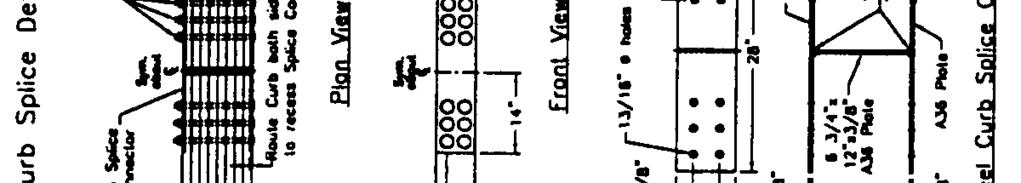
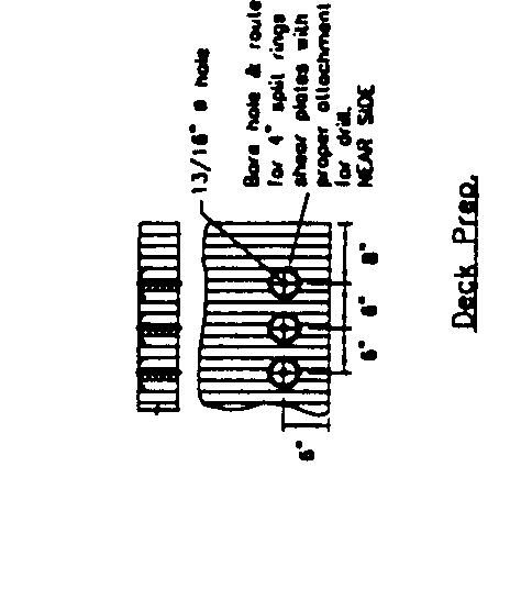
13 FIGURE 9 System No. 2: steel bridge railing design details (1 in. = 25.4 mm).

14 FIGURE 10 System No. 2: approach guardrail transition design details (1 in. = 25.4 mm).
15 Faller et al Paper No 5B FIGURE 11 Test STTR-1: (a) impact location, (b) vehicle damage, and (c) bridge railing damage.
16 348 Paper No. 5B0110 Transportation Research Record 1696 FIGURE 12 Test STTR-2: (a) impact location. (b) vehicle damage, and (c) bridge railing damage


17 Faller et al. Paper No. 5B FIGURE 13 Test SITA-3: [el impact location, lb1 vehicle damage, and [cl approach guardrail transition damage.


18 350 Paper No. 5B0110 Transportation Research Record 1696 FIGURE 14 Test STTR-4: (a) impact location, (b) vehicle damage, and (c) approach guardrail transition damage. REFERENCES


19 Faller et al. Paper No. 5B The contents of this paper reflect the views of the authors, who are responsible for the facts and the accuracy of the data presented here. The contents do not necessarily reflect the official views or policies of FPL or FHWA. This paper does not constitute a standard, specification, or regulation.
20 T R A N S P O R T A T I O N R E S E A R C H RECORD JOURNAL OF THE TRANSPORTATION RESEARCH BOARD No VOLUME 1 Fifth International Bridge Engineering Conference Bridges, Other Structures, and Hydraulics and Hydrology Papers presented at the Fifth International Bridge Engineering Conference April 3-5, 2000 Tampa, Florida A PEER-REVIEWED PUBLICATION OF THE TRANSPORTATION RESEARCH BOARD TRANSPORTATION RESEARCH BOARD - NATIONAL RESEARCH COUNCIL NATIONAL ACADEMY PRESS Washington, D.C. 2000