Festoon Manual Heavy Duty C-Track
|
|
|
- Dominic Hubbard
- 5 years ago
- Views:
Transcription


1 Festoon Manual Heavy Duty C-Track Heavy Duty C-Track Manual
2 CONDUCTIX INCORPORATED The technical data and images which appear in this manual are for informational purposes only. NO WARRANTIES, EXPRESS OR IMPLIED, INCLUDING WARRANTIES OF MERCHANTABILITY OR FITNESS FOR A PARTICULAR PURPOSE, ARE CREATED BY THE DESCRIPTIONS AND DEPICTIONS OF THE PRODUCTS SHOWN IN THIS MANUAL. Conductix makes no warranty (and assumes no liability) as to function of equipment or operation of systems built according to customer design or of the ability of any of its products to interface, operate or function with any portions of customer systems not provided by Conductix. Seller agrees to repair or exchange the goods sold hereunder necessitated by reason of defective workmanship and material discovered and reported to Seller within one year after shipment of such goods to Buyer. Except where the nature of the defect is such that it is appropriate, in Seller s judgment, to effect repairs on site, Seller s obligation hereunder to remedy defects shall be limited to repairing or replacing (at Seller s option) FOB point of original shipment by Seller, any part returned to Seller at the risk and cost of Buyer. Defective parts replaced by Seller shall become the property of Seller. Seller shall only be obligated to make such repair or replacement if the goods have been used by Buyer only in service recommended by Seller and altered only as authorized by Seller. Seller is not responsible for defects which arise from improper installation, neglect, or improper use or from normal wear and tear. Additionally, Seller s obligation shall be limited by the manufacturer s warranty (and is not further warranted by Seller) for all parts procured from others according to published data, specifications or performance information not designed by or for Seller. Seller further agrees to replace or at Seller s option to provide a refund of the sales price of any goods that do not conform to applicable specifications or which differ from that agreed to be supplied which non-conformity is discovered and forthwith reported to Seller within thirty (30) days after shipment to the Buyer. Seller s obligation to replace or refund the purchase price for non-conforming goods shall arise once Buyer returns such goods FOB point of original shipment by Seller at the risk and cost of Buyer. Goods replaced by Seller shall become the property of Seller. There is no guarantee or warranty as to anything made or sold by Seller, or any services performed, except as to title and freedom from encumbrances and, except as herein expressly stated and particularly, and without limiting the foregoing, there is no guarantee or warranty, express or implied, of merchantability or of fitness for any particular purpose or against claim of infringement or the like. Seller makes no warranty (and assumes no liability) as to function of equipment or operation of systems built to Buyer s design or of the ability of any goods to interface, operate or function with any portions of Buyer s system not provided by Seller. Seller s liability on any claim, whether in contract, tort (including negligence), or otherwise, for any loss or damage arising out of, connected with, or resulting from the manufacture, sale, delivery, resale, repair, replacement or use of any products or services shall in no case exceed the price paid for the product or services or any part thereof which give rise to the claim. In no event shall Seller be liable for consequential, special, incidental or other damages, nor shall Seller be liable in respect of personal injury or damage to property not the subject matter hereof unless attributable to gross misconduct of Seller, which shall mean an act or omission by Seller demonstrating reckless disregard of the foreseeable consequences thereof. Seller is not responsible for incorrect choice of models or where products are used in excess of their rated and recommended capacities and design functions or under abnormal conditions. Seller assumes no liability for loss of time, damage or injuries to property or persons resulting from the use of Seller s products. Buyer shall hold Seller harmless from all liability, claims, suits, and expenses in connection with loss or damage resulting from operation of products or utilization of services, respectively, of Seller and shall defend any suit or action which might arise there from in Buyer s name - provided that Seller shall have the right to elect to defend any such suit or action for the account of Buyer. The foregoing shall be the exclusive remedies of the Buyer and all persons and entitles claiming through the Buyer. 2 Heavy Duty C-Track Manual
3 TABLE OF CONTENTS SECTION - SAFETY 4 Safety Information Responsibility 4 Safety Messages 4 Electrical Warnings 4 Operational Warnings 4 Maintenance Warning 4 SECTION 2 - OVERVIEW 5 Specifications 6 Recommended Tools 6 SECTION 3 - INSTALLATION 7 Track Hanger Installation 7 Track Joint Assemblies Installation 7 Anchor Clamp Installation 8 Girder Clamp Installation 8 End Clamp Installation 8 Cable Trolley Installation 9 Tow Trolley / Control Box Trolley Installation 9 End Stop Installation 9 Installation of Cables 0 Tow Webbing Installation Tow Bar Pre-Assembled Festoon System Installation SECTION 4 - OPERATION 2 Pre-Operation Inspection 2 Operation Instructions 2 SECTION 5 - MAINTENANCE 2 Maintenance Instructions 2 Heavy Duty C-Track Manual 3
4 SECTION - SAFETY Safety Information Responsibility All owner, operator, and maintenance personnel must read and understand all manuals associated with this product before installation, operation, or maintenance. The manual provides information on the recommended installation, operation, and maintenance of this product. Failure to read and follow the information provided could cause harm to yourself or others and/or cause product damage. No one should install, operate, or attempt maintenance of this product prior to familiarizing themselves with the information in this manual. Safety Messages The following safety messages are used in this manual to alert you to specific and important safety related information. CAUTION CAUTION indicates unsafe actions or situations that have the potential to cause injury, and/or minor equipment or property damage. DANGER DANGER indicates hazards that have the potential to cause severe personal injury or death. WARNING WARNING indicates unsafe actions or situations that have the potential to cause severe injury, death, and/or major equipment or property damage. NOTE NOTE is used to alert you to installation, operation, programming, or maintenance information that is important, but not hazard related. Electrical Warnings Properly ground all electrical connectors in accordance with the National Electric Code, local codes, and ordinances. Disconnect and LOCK OUT / TAG OUT the electrical power from the system before any service is performed. Do not use cable for loads greater than the voltage and current rating. The capacity rating of the cable should be in accordance with the National Electric Code. Operational Warnings Exercise care when handling the festoon system during normal operation. Do not use cable different for which the system is intended. Change in diameter, weight per foot, length or flexibility of cable will affect the operation of the system. Mounting hardware and fasteners should be installed to maintain tightness under vibration and checked periodically to insure tightness. Maintenance Warning WARNING: Modification of this equipment may cause excessive wear and will void the warranty. Contact CONDUCTIX INC. regarding changes or modifications to this equipment. 4 Heavy Duty C-Track Manual

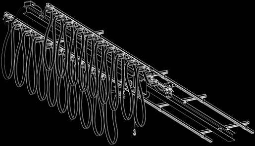
5 SECTION 2 - OVERVIEW End Clamp End Stop Installation 2 Endstops Needed per Control Side ( per end) Endstop Needed per Power Side ( at Fixed End) Tow Bar Installation Tow Trolley Installation Cable Trolley Installation Cable Installation Track Hanger Installation Track Joint Assembly Installation Anchor Clamp Installation Girder Clamp Installation Heavy Duty C-Track Manual 5
6 SECTION 2 - OVERVIEW Specifications Maximum trolley speed is 500 fpm. Maximum load per trolley is 80 lbs. C-Track material is 2 gauge galvanized or stainless steel. Loop depth of 3 ft. is typical unless otherwise specified. The loop depth is the distance from the top of the track to bottom of the cable loop. Maximum cable stack height is.5. Maximum recommended cable height is.65. For round cable the maximum recommended height is.38. Usable saddle width on cable carrier is 3.94 Recommended Tools Socket Wrench Torque Wrench /4 Open / Box End Wrench 7/6 Open / Box End Wrench /2 Open / Box End Wrench 9/6 Open / Box End Wrench /8 Allen Wrench Drill and Drill Bit Set 6 Heavy Duty C-Track Manual


7 Located longitudinal center line of runway where channel is to be installed. SECTION 3 - INSTALLATION If the C-Track is to be attached under a beam or stud, the hanger locations should be marked and drilled, or crossarm support installed. Track Hanger Installation 9/6 Open / Box End Wrench required. The track hanger is designed to be mounted on angle iron brackets with one mounting hole - can also be mounted on C-Track crossarm support or other suitable structures. One track hanger is required for each crossarm support bracket for each track run at 0ft. spacing (or 5ft. spacing for SST track). Extra track hanger and crossarm support bracket is required in storage area.. Slip the appropriate number of hangers on each section of C-Track. 2. Bolt the section loosely in place, joining the ends of the channels with splice joints as you progress. See Figure Align set screws with holes in C-Track and tighten. See Figure 7-. Track Joint Assemblies Installation 7/6 Open / Box End, /8 Allen Wrench 3/32 Drill Bit required. Track joints clamp for secure attachment and proper alignment of track section. Each kit includes four set screws and nuts. Welded splice assemblies are also available. See Figure Install the joints and tighten fasteners using a /8 Allen and a 7/6 open/box end or weld in place. See Figure If C-Track must be shortened, the hole pattern must be transferred to the new cut length. See Figure 7-3. Figure 7- Figure 7-2 Figure 7-3. Hole Pattern Heavy Duty C-Track Manual 7
8 Anchor Clamp Installation 9/6 & 7/6 Open / Box End Wrench required. SECTION 3 - INSTALLATION Anchor clamps are designed to hold the track in place while allowing free expansion of the system due to temperature changes. One anchor clamp is required per run and should be placed as close to the center of the system as possible.. In the center of the system, place an Anchor Clamp instead of a Track Hanger Clamp to anchor the system. The C-Track is now positioned into place. See Figure NOTE Do not overtighten screw. Clamp will spread apart and cause C-Track to lose support and possibly fall out. Girder Clamp Installation /2 Open / Box End Wrench required. Figure 8-. Anchor Clamp 2. Screw 3 Girder clamps are designed to hold the crossarm supports to the I-beam. Two girder clamps required per crossarm support.. Orient square nut flush against inside bottom surface of C-Track crossarm support. See Figure Tighten until clamp is flush with I-beam and crossarm is secured. See Figure 8-2. End Clamp Installation /2 Open / Box End Wrench required. The End Clamp is the first cable carrier at the fixed end of the festoon system. The End Clamp will always be the stationary component of the festoon system and does not have wheels. Typically only one is required per system.. Install the end clamp assembly at the far end of the fixed end of the C-Track and tighten fasteners to ft.-lbs. See Figure 8-3. Figure 8-2. Girder Clamp 2. Square Nut 3. Crossarm Support Surface 2 2 Figure 8-3. End Clamp 2. End Stop 8 Heavy Duty C-Track Manual


 per power side of festoon system. Install and tighten the end clamp and end stop(s) firmly in place.")
9 Cable Trolley Installation WARNING SECTION 3 - INSTALLATION Do not install trolleys in the C-Track until all hangers and splices are securely fastened to the recommended torque. The cable Trolley is the device with rollers that rolls inside the C-Track and carries the electrical cable down the track.. With the channel securely located, install the carriers into the slot of the C-Track. Place all trolleys into the track. See Figure 9-. Figure 9- Tow Trolley / Control Box Trolley Installation The Tow Trolley is the first cable carrier at the mobile end of a power festoon system. The Tow Trolley attaches to the crane power consumer usually with a tow arm. The Control Box Trolley is the first mobile carrier at the mobile end of a control festoon system. The Control Box Trolley consists of a mobile junction box or a quick disconnect connector to which a push button pendant may be wired.. Place the Tow Trolley / Control Box Trolley into C-Track the same as the Cable Trolley's crossarm support. See Figure 9-2. NOTE Tow bar should be centered top to bottom in tow box. This allows the crane or hoist to move up and down and not damage the tow trolley or the C-Track. Figure 9-2. Tow Bar End Stop Installation /2 Open / Box End Wrench required. One end stop is required for power systems, two are required for control systems with a control trolley to stop the trolley from rolling out of the C-Track. End stop quantities required: 2 per control side of festoon system ( on each end) per power side of festoon system. Install and tighten the end clamp and end stop(s) firmly in place. Torque fasteners for ft.-lbs. See Figure 9-3. On pendant control lines and / or systems where the active travel is near the end of the channel. It is advisable to install a second stop. 2 Figure 9-3. End Clamp 2. End Stop Heavy Duty C-Track Manual 9
 on top of stack (see diagram below).")
10 SECTION 3 - INSTALLATION Installation of Cables. Before beginning the installation of cables, remove the cable clamping pad assemblies from the tow trolley, trolleys, and end clamp. 2. Install cables on the equipment per the pre-designed arrangement or the following rules: 3. Arrange cables with the larger cables (power cables) on top of stack (see diagram below). This provides a larger bending radius as well as improved heat dissipation. Since the top cable also takes more pulling force during operation, the larger conductor is better suited to handle this force. Note the specified cable loop depth and allowance for hookup. 4. Arrange the cable package with a width to height ratio of 3 or 4 to. Tall narrow cable stacks can be unstable during operation. 5. Arrange cables with a minimum of 50% of each cable surface under clamp pressure (See diagram below). 6. Install tow webbing if required, see section 4.9 for instructions. 7. After setting the cables to the proper loop depth and arranging the cables as designed, re-install the cable clamping pad assemblies. Be sure the smallest cables do not move when pulled. 8. As an alternative method, cable may be clamped in the saddles prior to installing the carriers on the channel. Figure Heavy Duty C-Track Manual


11 SECTION 3 - INSTALLATION Tow Webbing Installation Tow webbing is used in both High Speed and Outdoor applications to reduce the shock and pulling tension on the electrical cable. The tow webbing is installed on top of the electrical cable and held in place by the saddle on the cable trolley. See Figure -. The webbing length is generally 3 inches less than cable per loop of the length of the cable between cable trolleys. Contact factory for high speed applications to determine webbing length. See Figure -. Tow Bar The tow bar is fixed to the crane and is designed to engage tow box to move festoon system.. Install the tow bar on the crane or system that is to be electrified. Center and align tow bar with the Tow Trolley. See Figure -2. Pre-Assembled Festoon System Installation Pre-assembled festoon systems are typically built and shipped installed on a C-Track Channel by Conductix Wampfler. Upon arrival at the job-site, inspect the festoon system to insure electrical cables and festoon components have not been damaged during transit.. Attach hoisting cables at each end of the pre-assembled festoon C-Track and lift into position. The shipping C-Track mobile end must align with the permanent festoon C-Track. 2. Remove the end stop from the mobile end of temporary C-Track and roll the Tow / Control Box trolley and succeeding cable trolleys into the permanent C-Track. 3. Make mechanical connections of towing arm and insure all end stops are applied and tightened. 4. Make electrical connections as required. 2 Figure - Figure -2. Trolley 2. Tow Webbing Heavy Duty C-Track Manual
12 Pre-Operation Inspection. The festoon system is now installed. Prior to hookup and application of power, the carrier should be cycled manually, if possible. 2. Check for proper mounting of end clamps. 3. Check for obstructions of channel joints. SECTION 4 - OPERATION 4. Check cable for proper loop depth, freedom of travel, and stretch-out. 5. On pendant systems, check for proper spacing of the pendant to the floor, and connect this cable in the junction box. 6. The cable connections now can be made to the power unit and the source, using the appropriate cable strain relief bushing(s). Operation Instructions Do not exceed the voltage or amperage rating of the cable. Overheating, fire, damages to equipment or personal injury could result. Operate the festoon system within the electrical and mechanical limits it was intended. SECTION 5 - MAINTENANCE Maintenance Instructions All trolleys are lubricated and sealed for life, therefore no re-greasing is required. However, customers should conduct periodic inspections of the system. Determine the inspection intervals based on duty cycles and environment. The following checks are recommended during inspection:. Check all rollers for wear 2. Check tightness of all hardware. (See torque specifications) 3. Check cable clamps on all trolleys, making sure cables remain secure. 4. Inspect cable for any cuts or cracks. 5. Check channel for wear, and clear the running surface of any debris. 2 Heavy Duty C-Track Manual
13 Heavy Duty C-Track Manual 3