PLANNING GUIDE MODULAR BI-FILE
|
|
|
- Chrystal Skinner
- 5 years ago
- Views:
Transcription

1 RAIL SYSTEM Modular Bi-File maximizes filing and storage in minimal space. The concept is simple. Two rows of filing equipment placed in nearly the same footprint where there was once, only one. The front row of filing equipment rests on movable carriage that travels back and forth. This movement allows access to the back row of stationary filing equipment. The net result is a high-efficiency storage system that virtually doubles the current, stationary filing and storage capacity. Rail is the basis of all mobile systems. The rail provides for a smooth, guided and calculated transition of the filing equipment from one position to another. The Modular Bi-File provides a levelable, surfacemounted rail, which allows quick and easy installation. LEVELABLE RAIL Extruded aluminum alloy that provides a lightweight, nongrouted, non-anchored rail alternative to permanent installations. Designed to sit on top of existing floor covering with leveling capabilities. Center flange rail is levelable and incorporates 1-1/2" (38 mm) appliance levelers. Levelers 8" (203 mm) on center. Both sides of rail. Height of 1-1/2" (38 mm) from base to top. 2-7/8" (73 mm) base flange. Incorporates an in-rail anti-tip feature. Uplift capacity of 900 lbs. (1339 kg) per in-rail anti-tip. Designed to hold the modular floor. SPLICE Two or more rail sections require a splice plate at each joint. Splice plates are also required at the both ends of the rail. Splice plate constructed of 11-gauge galvanized steel. Splice plate included in the rail assembly. RAMP The ramp provides a smooth transition from the existing floor to the top of the raised floor on the Modular Bi-File system. Extruded aluminum alloy with a pivot extension. Approximate depth of 4-1/2 (114 mm) when installed. Pivot extension rests on rail edge. Ramp end cap eliminates ramp movements and is required at both ends of the ramp. Note: This ramp does not comply to the American with Disabilities Act of 1990 (ADA) standard. Contact Spacesaver for information on a ADA ramp. PG /07 Page 1 of 7
2 MODULAR FLOOR Whenever levelable rail is installed on top of an existing floor, a raised floor is required between the rails to compensate for rail height. This allows for easy access and eliminates the tripping hazard of the rail. The Modular Mobile system offers two floor types, Vinyl coated or Uncoated. Vinyl Coated: constructed of 3/4 (19 mm) oriented strand board (OSB) with vinyl-coated surface (gray or tan). Uncoated: constructed of 3/4 (19 mm) 7-ply exterior grade plywood where no top surface is applied. (Optional fire-retardant plywood is available. Contact Spacesaver.) Floor sections are grooved (routed) in two places on the underside of the floor. This allows the section to rest on the rail and is the basis for leveling. Groove cut (routed) on each end of the sections allow the floor sections to be spliced together. Splice plates are 6" (152 mm) x 3/4" (19 mm). Splice plates constructed of 11-gauge galvanized steel. MODULAR FLOOR Side View Splice Plate Opening End View Rail Groove The floor panels are available in widths of 24 (608 mm), 30 (760 mm), 36 (912 mm), 40.5 (1029 mm), 42 (1064 mm), 43.5 (1105 mm), 45 (1143 mm) and 48" (1216 mm). The available depths of the floor panels are 12" (304 mm), 13" (329 mm), 15" (381 mm), 16" (405 mm) and 18" (458 mm). The depth of the floor panels must match the nominal shelving depths. FLOOR END COVERS AND SIDE COVERS The end covers are used to cover the unfinished floor panel edges and the rail ends. They are attached to the top surface of the floor panel with wood screws. It gives the modular floor a "finished" look at both ends of the system. The end covers and side covers will be finished the same color that is selected for the mobile carriage or stationary platforms. End covers are included in the mobile carriage and stationary platform assemblies. End covers constructed of 18-gauge steel. PG /07 Page 2 of 7
3 HOW TO ORDER RAIL, RAMP AND FLOOR Even though the Spacesaver pricing software (Configura) will automatically calculate necessary parts and pieces that generate a complete bill of material, this planning guide explains how to configure components manually. 1. Look up Table 1 on next page. 2. Determine the system configuration desired. Locate the desired configuration on the far left column. a. Bi-File: 2x1, 3x2, 4x3, 5x4, 6x5. The first digit represents the number of platforms and the second is the number of mobile carriages. Tri-File is available, but not shown on chart. Example: Find 4 x 3Locate the desired configuration on the far left column. 3. Determine width combinations of 4-Post and Case-Type shelving/platforms to calculate system width a. This will be the sum of platform shelving widths, platform spacers and end stops width. Sum = platform shelving widths + [1.5 x (number of platforms +1)] Example: 4 x 3 shelving platform of 36, 36, System width = ( ) + [1.5 x (4 + 1)] = Determine Rail and Ramp: Locate the section identified as Rail and Ramp Catalog Numbers at the top center of the table. The intersection of the line and column identifies the quantity and catalog number for both the Rail (LRLxx) and Ramp (RPxx). Note multiple sections may be required. Example: Using a 4 x 3 configuration and 36, 36, 42, 42 with 15 deep 4-Post and Case-Type shelving and a system length of (4.15m). a. For Ramp, use the value indicated and the catalog number RPxx. Ramp requirements: 1-RP48, 1-RP56 and 1-RP60. b. For Rail, double the value indicated and use the catalog number LRLxx. Rail requirements: 2-LRL48, 2-LRL56 and 2-LRL Determine Floor: Locate the section identified as Floor Panel Catalog Numbers at the top right of the table. a. The intersection of the line and column identifies the quantity and catalog number for both types of Floor (FP xx ) 1. The first _ represents the shelving depth of 12, 13, 15, 16, The xx represents the floor panel section length. 3. The last _ represents the floor type: VG for gray vinyl covering, VT for tan vinyl covering, or no suffix for uncoated flooring. Example: Floor Requirements (using our 4x3 configuration with 15 deep shelving) with gray vinyl covering: 1-FP1530VG, 1-FP1542VG, 1-FP1544VG and 1-FP1548VG. PG /07 Page 3 of 7
,")

")
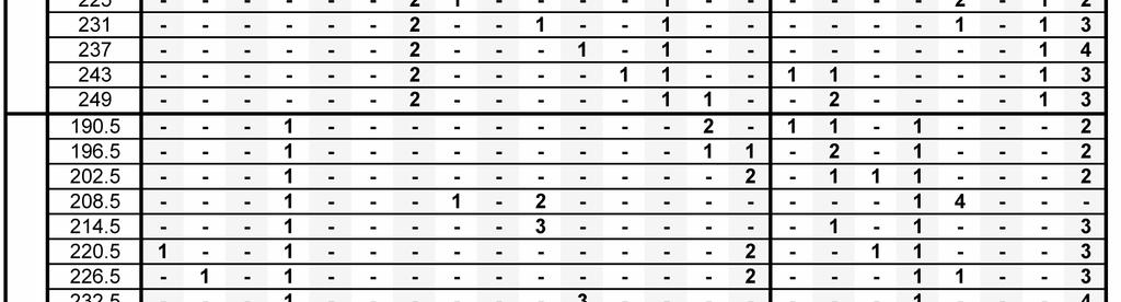
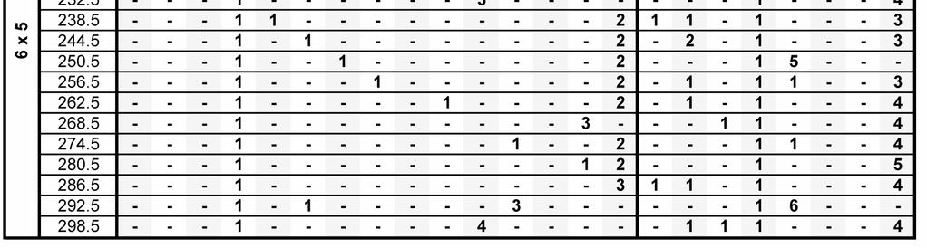
4 RAIL (LRL), RAMP (RP) AND FLOOR PANEL (FP) COMBINATIONS PG /07 Page 4 of 7
5 MODULAR LATERAL CONFIGURATOR DRAWING PG /07 Page 5 of 7
6 CARRIAGE AND PLATFORM The mobile carriage and stationary platforms are the workhorse components of any mobile system. These components accept the storage equipment that will hold the material to be stored. Order carriage and platforms in quantities and sizes that conform to quantities and sizes of 4-Post and Case-Type shelving to be mounted on the Modular Bi-File track storage system. Each carriage section is engineered for durability and designed for modularity. Designed to mobilize 4-Post and Case-Type shelving. 4-Post and Case-Type shelving range from 6 openings at a height of 64-1/4 (1632 mm) to 9 openings at 97-1/4 (2470 mm). Shelving from 64, 76, 85, 88, 97 with openings 4-9. Constructed of 14-gauge steel. 500 lbs. (227kg) per lineal carriage foot (305 mm) carriage and platform capacity. (Based on 18 x 48 carriage w/5-high x-ray loads.) Carriage Height of 3-3/8 (95 mm). (Carriage ht + Rail ht = 3 3/ = 4.7/8 total) Wheel housing carries the weight of the storage equipment and media. Stationary platforms contain, in place of the wheels, a galvanized bracket that is used to level the platform. Widths and depths are the same as indicated above for mobile carriage and stationary platforms. Any size deviation must be approved by Spacesaver. Note: Bumpers removed for clarity PG /07 Page 6 of 7
7 IN RAIL ANTI-TIP The in-rail anti-tip device is attached to the carriage or platform. It serves multiple purposes. Provides a security feature that "locks" the side and end covers in place so they cannot be removed while the anti-tip is attached. Provides the vehicle to secure the shelving uprights to the carriage or platform. Ties the mobile system into the rail. The translucent bumper provides protection of the carriage when they are moved as well as gives the finished look to the carriage or platform. OVERHEAD ANTI-TIP The overhead anti-tip device is attached to the shelving uprights. The overhead anti-tip is required when the shelving height plus carriage height exceeds a 6:1 ratio to the shelving depth. The overhead anti-tip adds stability to a mobile carriage/shelving with excessive height to width ratios. Configura will automatically select the overhead anti-tip based on the shelving height. Example: 76 (1.9 m) x 12 (304 mm) shelving has a height to width ratio of ( /8 + ½ ) 12 = Since this is over the 6:1 ratio, it will require an overhead anti-tip. PG /07 Page 7 of 7