|
|
|
- Allison Dulcie Scott
- 5 years ago
- Views:
Transcription


1
2 Contents 1 Notes Product Introduction Production Instruction Product Feature Product Structure Dimensions Technical Parameters P HD CVI Camera Menu Instruction CAMERA MENU SETTING Product Installation Note Installation Tools and Information Installation Method Monitoring Equipment Connection Cable Connection Diagram Appendix: FAQ
3 1 Notes Read this manual carefully before use. A. To reduce the risk of electric shock, do not open the machine and maintain by yourself, please consult a professional service person. B. To prevent fire or shock hazard, use the power after safety certification, the input voltage, current, voltage polarity and operating temperature must meet the requirements of this camera. C. Please note the operating temperature and environmental requirements of the camera, avoid too low or too high temperature. General operating temperature range of -10 ~ +50 (Fahrenheit temperature is 14 ~122 ). Avoid flooding and rain, minimize dust and moisture erosion, otherwise camera would be damaged. D. Cameras in use should avoid direct sunlight, glare, otherwise the sensor will be damaged. E. Do not touch the sensor surface, if any foreign objects exits, a cotton swab or lens cloth can be used to wipe, if it is difficult to remove, a neutral detergent diluted with water would be useful. Do not use corrosive solution. F. In order to make the camera work smoothly and obtain a satisfactory image, the power cord and video connection cannot be too long; otherwise the increase of line loss will lead to the inadequate magnitude of the operating voltage of the camera or video signal. G. In order to prevent the camera from falling, please do not place the camera on an unstable bracket, base or other unstable objects. Otherwise it will lead to injury, at the same time, the camera will be damaged
4 H. The camera can not be placed near the radiator or heating resistor. 2 Product Introduction 2.1 Production Instruction This series of cameras are adopted CMOS image sensor with high performance, which provides mega pixel resolution and supports HD video. Moreover, it supports monitoring signals coaxial transmission. Transmission distance can reach up to 500M using RG-59 coaxial cable. The series can support both CVI/CVBS 960H output as well as realize high speed, long distance and real time video transmission. 2.2 Product Feature Coaxial cable adopted,bnc connector as cable standard HD VCI/CVBS dual output Auto Day/Night(ICR) Auto Defog Digital WDR 8X Digital Zooming Motion Detection, Privacy Mask Auto Iris(Specific models) Back-end support optical zoom (motorized zoom lens models) Voltage Input: DC 12V - 2 -


5 3 Product Structure 3.1 Dimensions The following are the HD-CVI Camera dimensions. Photo: ELI-ACVI-ED21-4R Photo: ELI-ACVI-ED21-312MR - 3 -

6 Photo: ELI-ACVI-B21-4R Photo: ELI-ACVI-B21-312MR - 4 -
7 4 Technical Parameters P HD CVI Camera Image Sensor Image Effective Pixels Resolution S/N Ratio Min. Illumination Scanning System Video Output 1/ MP SONY Exmor CMOS 1984(H) 1105(V) Digital: p;Analog: 700TVL 50dB (AGC Off) ON);0Lux IR ON Progressive Digital: HD-CVI ;Analog: 1Vp-p Composite Output(75Ω/BNC) Function Day&Night EXTERN,COLOR, B&W, AUTO Exposure Auto White Balance Auto Backlight Compensation Auto Defog OFF/ON DNR 2D+3D NR WDR OFF/LOW/MIDDLE/HIGH Smart IR Level Optional Privacy Mask ON/OFF (16 Areas) Motion Detection ON/OFF (4 Areas) General specification Input Voltage DC12V±10% Operation temp -10 ~+50 (14 ~122 ) Operation humidity <85%RH (Non-condensation) - 5 -


8 5 Menu Instruction 5.1 CAMERA MENU SETTING MAIN MENU EXPOSURE SETTING WHITE BALANCE SETTING - 6 -


9 DAY & NIGHT SETTING IMAGE SETTING SPECIAL SETTING - 7 -

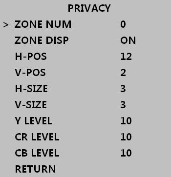
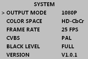
10 SPECIAL-SYSTEM SETTING 1080P SPECIAL-COMMUNICATIONS SETTING SPECIAL-PRIVACY SETTING - 8 -


11 SPECIAL-MOTION DETECTION SETTING SPECIAL-SHADING HOMOGENIZATION SPECIAL-ADJUSTMENT SETTING - 9 -
12 6 Product Installation 6.1 Note 1) Make sure the unit is powered off before installation. 2) Check power supply voltage consistent with the electric voltage to prevent voltage shortage, resulting in damage to the device. 3) Do not use in an environment beyond the boundaries of the temperature -10 ~+50 (14 ~122 ), and maintain good ventilation to prevent moisture build up, and to reduce the risk of fire or electric shock. 4) The installation and maintenance of this product should be professional, please do not in any way remove or modify the equipment; only use the accessories recommended by the manufacturer. Problems caused by unauthorized repair are at your own risk. 6.2 Installation Tools and Information Prepare the required engineering data and instructions. Before installation please prepare the following tools and instrumentation: A straight or a Phillips-head screwdriver, multi-meter, scissors, needle nose pliers, tape measure, and writing utensils
13 6.3 Installation Method 1. Check the equipment to make sure it is not damaged. (Contact your retailer if equipment is damaged) 2. Mounting bracket or base. 1 Cement wall installation: Install the expansion screws (expansion screw holes need stand or base hole), and then mount bracket or base. 2 Wood/ Dry wall Installation: use self-tapping screws to mount. 3. Mounting the camera a. Dome Camera Adjust the lens position and aim it at the monitoring points to present a clear picture, manually fix lens location and adjust the hemisphere cover. Re-examine the screen to make sure visual image meets the requirements. Tighten the hemisphere cover. b. Bullet Camera Adjust the body so that the lens aims at the monitoring points and presents a clear picture. Tighten the screws, to ensure that it does not move. Installation method above is for reference only. Note: The wall needs to bear at least 3X weight of bracket (base) and camera
14 7 Monitoring Equipment Connection 7.1 Cable Connection Diagram Photo 7-1 * Note: HDCVI interface connects HD CVI DVR CVBS interface connects 960H DVR The cable connection diagram above is for reference only. Pls go by actual equipment for the concrete operation
15 8 Appendix: FAQ Q: No picture with device powered on A: May result from abnormal power supply. Please check if the power supply voltage and polarity are correct. Check to see if wires/ cable connections and monitors are secure. Q: Unclear image output A: Can be caused by incomplete adjustment of the lens back focus. Loosen the fixed screw of the lens until it turns clear. If that does not work, please check to see if the lens is in good condition. Also check for foreign objects on the lens surface and sensor surface. If foreign objects exits, it can be wiped away by cotton swab or lens paper. Q: Horizontal interference fringes on image A: This phenomenon is generally caused by too strong of hum from power supply, which should to be filtered out. This issue may also be related to the type of monitor used or peripheral devices. Q: Constant change of ground color of image A: This phenomenon is caused by color scrolling, which is mainly due to alternating electromagnetic fields generated by fluorescent lamps. It can be weakened with two methods: one is to reduce the usage of fluorescents. The other is to enlarge the distance between the camera and the fluorescent lamp. To overcome it thoroughly, please select LL synchronization camera


16