Chapter IV - Alternatives
|
|
|
- Fay Strickland
- 5 years ago
- Views:
Transcription
1 Chapter IV - Alternatives The purpose of this chapter is to identify and evaluate alternatives for the future development of T. F. Green Airport that address the needs identified in Chapter III, Demand/Capacity and Facility Requirements. The process of determining the future development of T. F. Green began during the visioning process that took place at the beginning of the Master Plan. This visioning process helped affirm the future role of the airport. Based on a continuation of the airport s existing role and using industry and Federal Aviation Administration (FAA) planning standards, the facility requirements analysis in Chapter III identified the following needs for T. F. Green: Main runway length of 9,500 feet (existing length is 7,166 feet) Crosswind runway length of approximately 7,600 feet (existing length is 6,081 feet) Additional 7,500-foot parallel runway (none previously planned) Standard FAA Runway Safety Areas (RSAs) for all runways Closure of the short runway (Runway 5L-23R) to reduce the potential for runway incursions Taxiway improvements 18 additional passenger boarding gates and more than double the amount of terminal building space (existing 352,000 square-foot terminal has 22 gates) Over 9,000 additional public, employee, and rental car parking spaces (9,070 parking spaces today) Expansion of the on-airport roadways Expansion and/or relocation of various airport support facilities As described in this chapter, the Rhode Island Airport Corporation (RIAC) Board considered the full ramifications of the range of options that fulfilled the 20-year needs and decided not to pursue the full needed development at this time. Instead, to minimize any potential community and environmental impacts, the Board decided to pursue abbreviated alternatives that meet the short-term needs of the airport as shown in Table IV-1. Table IV-1 FACILITIES ACCOMMODATED IN THE PLAN T. F. Green Airport Facility Theoretical Needs What the Plan Accommodates Main Runway 9,500 feet long 7,500 feet long Crosswind Runway 7,600 feet long 7,500 feet long Parallel Runway 7,500 feet long Parallel runway not pursued Terminal/Gates 40 gates 40 gates Chapter IV Alternatives IV-1 December 2002
2 IV.1 Alternatives Process The T. F. Green Airport Master Plan alternatives analysis followed a multi-step process as depicted on Exhibit IV.1-1. The focus of the initial steps was the long-term layout of the airfield because it requires the greatest commitment of land area. Once preferred airfield alternatives were identified, terminal, automobile access, auto parking, and support facilities alternatives were considered. Three meetings were held with the Study Resource Committee (SRC) to obtain input from stakeholders on the T. F. Green alternatives. The first meeting on April 25, 2002 allowed the SRC to provide ideas on future concepts and potential evaluation criteria. In addition, input was obtained from RIAC staff to determine if there were any current operational inadequacies that needed to be addressed. These ideas were used, together with analysis by the master plan team, to develop a full range of airfield concepts, including a do nothing scenario, closure of the airport, minimal growth beyond the airport boundary, minor improvements to correct existing operational deficiencies and improve safety, runway extensions, and new parallel runways. Appendix F contains the full range of initial concepts. After the development of the initial list of alternatives, RIAC decided that it was not willing to consider 20-year airfield concepts with extreme impacts (such as widely spaced parallel runways) at this time. RIAC then instructed the team to specifically consider concepts that fall short of the 20-year needs identified in Chapter III, Demand/Capacity and Facility Requirements, along with concepts that do meet the 20-year needs. Based on this decision by RIAC, 15 airfield concepts were developed that focused on minimizing impacts to the communities surrounding the airport. Most of the concepts were suggestions from the SRC from the April 25, 2001 meeting and fall short of accommodating the 20-year requirements. Three of the concepts did include the development to meet the 20-year requirements. These three concepts include two main parallel runways and a 7,600-foot crosswind runway. Prior to the next scheduled SRC meeting on June 5, 2002, RIAC decided to not pursue the three concepts that included an additional parallel runway. The remaining 12 concepts were reviewed with the SRC on June 5, After the June 5 meeting, the airfield concepts were evaluated, incorporating input from the SRC. This evaluation led to a recommendation from the master plan team, which was presented to the SRC on July 11. Concepts A7, A8, and A9 were found to be acceptable by the master plan team based on FAA standards, RIAC s desire to keep the main Runway 5R-23L on airport property, and the need for a 7,500-foot long crosswind runway. All three alternatives include the extension of Runway 5R-23L within the existing airport property boundary, providing 7,500 feet in length. The three alternatives include the closure of Runway 5L-23R and extension of Runway to the same length as Runway 5R-23L. The selection of these alternatives represents a compromise between community needs and meeting the identified facility needs. Any Chapter IV Alternatives IV-2 December 2002
3 of these alternatives would allow RIAC to maintain its current service with the forecast fleet but all would preclude most or all nonstop west coast service. Most demand would be able to be accommodated, albeit at higher congestion and delay levels than experienced today. Of the three concepts, Concept A7 was identified as the best compromise between community impacts and wetland impacts based on the limited information available in the Master Plan. Because the detailed community and actual environmental data and assessment will take place in the Environmental Impact Statement (EIS), the RIAC Board decided to let the EIS process determine which alternative is best. Therefore, the Board officially recommended that Concepts A7, A8, and A9 be evaluated in the EIS. Alternatives were developed and presented to the SRC on July 11, 2002 that considered terminal, automobile access, auto parking, and support facility improvements. Many of these functional areas are interrelated and affect the development potential of each other. Therefore, all areas were examined both individually and collectively to ensure the final plan is functional, efficient, cost effective, and minimizes environmental and community impacts. A development plan for the terminal, automobile access, auto parking, and support facilities was identified based on this analysis and was approved by the RIAC Board on July 17, A Master Plan public workshop was held on July 25, concurrently with the EIS workshop and scoping meeting. The above analysis was presented in a workshop format to the public. The alternatives analysis in the Master Plan sets the long-term direction of T. F. Green and as such provides input for the EIS alternatives analysis. However, the EIS evaluates projects needed in the foreseeable future for which approval will be sought while the Master Plan considers 20-year needs. (Approval of a master plan is always conditional on environmental approvals.) As a result, the EIS may develop and evaluate variations of the alternatives considered in the Master Plan, or even entirely new alternatives. IV.2 Airfield Airfield facilities are the focal point of an airport complex. The runway system takes up the majority of an airport and the physical characteristics of various airfield concepts directly influence the nature of the other airport facilities. As a result, airfield concepts are considered first, before the other facilities at the airport. The identification and evaluation of runway development concepts involved a three-step process and policy decisions by RIAC. Chapter IV Alternatives IV-3 December 2002
4 IV.2.1 Round 1 Runway Alternatives Evaluation As discussed previously, SRC and RIAC staff input helped the consultant team develop a full range of airfield concepts. These concepts are contained in Appendix F. The initial range of airfield concepts was developed to address the airfield needs identified in Chapter III, Demand/Capacity and Facility Requirements, as summarized below: Meet FAA safety standards Provide additional arrival and departure capacity Provide additional runway length based on the following parameters 1 : - General aviation departures require 5,000 feet - Commuter departures require 6,400 feet - Air carrier departures to existing destinations require 7,500 feet - Air carrier departures to future destinations require 9,500 feet (non-stop) - Arrivals require 7,200 feet - Crosswind runway length should be 80 percent of main runway (7,600 feet) Improve existing operational deficiencies Minimize community impacts Minimize environmental impacts Provide flexibility to respond to changes in future aviation demand Four groups of concepts were developed based on the above objectives and needs: Group A concepts primary goal is to have minimal or no development of the airfield. These concepts fall short of meeting the facility requirements identified in Chapter III, Demand/Capacity and Facility Requirements. Group B concepts aim to provide the needed capacity enhancements by providing two parallel runways (in addition to the crosswind runway) with 1,200 to 2,500 feet of lateral separation between the runways, which yields varying levels of dependence. A 1,200-foot separation is the separation required for Design Group V or VI 2 aircraft in order to allow simultaneous operations in good weather. A separation of 2,500 feet allows simultaneous arrivals and departures or simultaneous dual departures in poor weather, but not simultaneous arrivals. 1 2 Runway length requirements were identified for several aircraft groups (air carrier, commuter, general aviation), in addition to landing and takeoff requirements. These requirements do not imply that several different runways are needed to serve different aircraft groups. Rather, various runway length requirements were identified in order to provide as much information as possible for the alternatives analysis. Group V and VI include aircraft with wingspans of 171 feet up to but not including 262 feet (examples include the MD-11, Boeing 767, Boeing 747, and Boeing 777). Chapter IV Alternatives IV-4 December 2002
5 Group C concepts increase capacity by providing two parallel runways (in addition to the crosswind runway) that are separated laterally by 4,300 to 3,000 feet, which yields varying levels of independence. The normally approved minimum separation for dual independent approaches is 4,300 feet. The FAA will consider a minimum of 3,000 feet where 4,300 feet is impractical. Group D concepts increase capacity by using two parallel runways (in addition to the crosswind runway) with 5,000 feet of lateral separation, which yields independent parallel runways. A 5,000-foot separation is the recommended separation for simultaneous dual operations in all weather conditions (although as noted above, the FAA will consider a minimum of 3,000 feet lateral separation). All of the initial concepts would provide standard RSAs for Runway As discussed in Chapter II, Forecasts of Aviation Demand, Section II.5.2, Reduce Facilities, Runway does not meet current FAA RSA design standards. This runway needs to be reconstructed in the next several years due to the age of the pavement and when this occurs, standard RSAs will be required. The FAA standard calls for an RSA on Runway that extends 1,000 feet beyond the runway ends and is 500 feet wide. 3 In certain cases where it is not practicable in the FAA s opinion to achieve a standard RSA, the use of declared distances or Engineered Materials Arresting System (EMAS) can provide an alternative means of enhancing safety. The application of declared distances involves treating an aircraft s runway landing and takeoff performance distances independently. The use of declared distances provides more runway length for departures because it is not necessary to provide an RSA behind a departing aircraft. Although there are roads and wetlands off the runway ends, there are no barriers (such as sharp drop-offs) that prevent standard RSAs from being achieved with the desired runway length for Runway As a result, declared distances and EMAS are not viable options and are not considered in any of the alternatives with the exception of the No Build Alternative, which assumes the length of Runway is maintained but does not specify how standard RSAs are provided. After reviewing the full list of concepts and considering the input received at the April 25, 2002 SRC meeting and the RIAC Board s goals and objectives for the long-term vision of T. F. Green, RIAC decided that it was not willing to consider 20-year airfield concepts with extreme impacts (such as widely spaced parallel runways) at this time. RIAC then instructed the team to specifically consider concepts that fall short of the 20-year needs identified in Chapter III, Demand/Capacity and Facility Requirements, along with concepts that do meet the 20-year needs. This policy decision by RIAC resulted in elimination of all of the Group C and D concepts and most of the Group B concepts. It also resulted in the addition of new Group A concepts. 3 FAA Advisory Circular 150/ Change 6, page Chapter IV Alternatives IV-5 December 2002
6 IV.2.2 Round 2 Runway Alternatives Evaluation The 15 concepts that were evaluated in Round 2 are shown on Exhibit IV.2-1, Exhibit IV.2-2, Exhibit IV.2-3, Exhibit IV.2-4, Exhibit IV.2-5, Exhibit IV.2-6, Exhibit IV.2-7, Exhibit IV.2-8, Exhibit IV.2-9, Exhibit IV.2-10, Exhibit IV.2-11, Exhibit IV.2-12, Exhibit IV.2-13, Exhibit IV.2-14 and Exhibit IV.2-15 which also list the pros and cons of each concept. Concepts A1 through A12, many of which are suggestions from the SRC from the April 25, 2001 meeting, fall short of meeting the 20- year needs. Concepts B1 through B3 4 meet the 20-year requirements and include two parallel main runways (one of which is 9,500 feet long) and a 7,600-foot crosswind runway. Round 2 Concepts Below is a description of each concept. Concept A1 assumes T. F. Green Airport is closed and all service is replaced at either a new airport or existing airports in the region. Concept A2 considers relocating the passenger and/or cargo service to other airports. T. F. Green remains open to serve the traffic that remains. This concept assumes Runway is reconstructed in the current runway envelope and shortened to 4,500 feet in order to provide full RSAs. No other development would occur and Runway 5L-23R would remain open. Concept A3 considers shrinking the airport by closing Runway 5L-23R and reconstructing Runway in the current runway envelope shortening this runway to 4,500 feet. This concept assumes no other development occurs and that the airlines would continue to use T. F. Green to the maximum extent possible in spite of the reduced facilities. Concept A4 is the no build concept. This concept assumes the length of Runway is maintained in its current location and that RSAs are provided in some manner on either end of the runway either with declared distances or EMAS, or full RSAs which would possibly require the relocation of Airport Road or intrusion into the wetlands. Runway 5L-23R would remain open in this concept. Concept A5 includes extending Runway 5R-23L to the south to a length of 7,500 feet, which is the maximum length that can be achieved while still remaining on airport property. Runway would be shortened on the northwest end (in order to provide a full RSA on the Runway 16 end without impacting Airport Road) and extended to the southeast in order to maintain its existing length of 6,188 feet. Runway 5L-23R would be closed. The only way to extend Runway 5R-23L within the existing airport property boundary is to the south because the RSA and object free area (OFA) on the 4 Concepts B1, B2, and B3 were derived from concepts B6, B7, and B10 in Appendix F but were changed to B1 through B3 for ease of discussion. Chapter IV Alternatives IV-6 December 2002
7 northern end of the runway extend some 170 feet past the edge of the property boundary. There is approximately 1,700 feet of property to the south of Runway 5R-23L that can be considered for an extension to this runway. However, an extension to the south is limited by several factors. There is an airport service road and a cemetery along the airport property boundary that limits RIAC s ability to extend the runway to the edge of the property. Further, the need to position the Instrument Landing System (ILS) outside the 1,000-foot RSA further limits the ability to extend the runway to the south on airport property. These constraints allow a shift of the southern threshold by 500 feet to the south. The net extension is reduced due to the lack of a full RSA and OFA on the north end of the runway, the correction of which necessitates a 170-foot shift of the northern threshold to the south. This yields a maximum length of 7,500 feet for Runway 5R-23L while remaining on airport property. Concept A6 includes shifting and extending Runway to the southeast to be slightly longer than Runway 5R-23L (7,200 feet). Runway 5R-23L would be maintained at its current length of 7,166 feet. Runway 5L-23R would be closed. Concepts A7 through A9 include extending Runway 5R-23L to 7,500 feet as in Concept A5. Runway 5L-23R would be closed. In addition, Runway would be extended to a length of 7,500 feet. The three concepts differ in the location of Runway Concept A7 includes extending Runway to the southeast, while maintaining the existing Runway 16 threshold. Concept A8 includes shortening Runway on the northwest end (in order to provide a full RSA on the Runway 16 end without impacting Airport Road) and extending the runway to the southeast. Concept A9 assumes Runway is extended to the northwest to the maximum extent possible, with the remainder of the extension to the southeast. Concept A10 and A11 include extending Runway 5R-23L to 7,500 feet as in Concept A5 and A7 through A9. Runway 5L-23R would be closed in both concepts. Runway would be extended to 7,600 feet so that it becomes the main runway and is used more often than Runway 5R-23L. Runway would be shortened on the northwest end (in order to provide a full RSA on the Runway 16 end without impacting Airport Road) and extended to the southeast in Concept A10. With Concept A11, this runway would be extended to the northwest to the maximum extent possible, with the remainder of the extension to the southeast. Concept A12 considers extending Runway 5R-23L by 500 feet to the south and approximately 330 feet to the north to a length of 8,000 feet. Runway would be shifted (in order to provide a full RSA on the Runway 16 end without impacting Airport Road) and extended to the southeast to 8,000 feet in length. Runway 5L-23R would be closed. Concepts B1 through B3 each include a 7,600-foot crosswind runway. Runway 5R-23L would be extended to a length of 9,500 feet. In addition, a new 7,500-foot runway would be constructed parallel to existing Runway 5R-23L with 1,200 feet of lateral separation. Runway 5L-23R would be closed. Chapter IV Alternatives IV-7 December 2002
8 After considering SRC input and the community impacts of major expansion (Concepts B1 through B3), RIAC decided not to pursue a second parallel runway or a full extension of Runway 5R-23L (to 9,500 feet). The policy decision by RIAC to not provide a new parallel runway means that demand within the 20-year period is projected to approach and then ultimately exceed the capacity of the airfield. If demand materializes as expected in the forecast, delays will be nearing an average of six minutes per operation and the airfield will be operating at over 100 percent of its capacity by As analyzed and discussed in Chapter II, Forecasts of Aviation Demand, Section II.5.2, Reduce Facilities, the forecast air carrier, commuter, and cargo demand would still likely materialize but 25 to 50 percent of the forecast general aviation activity may choose to use one of the other Rhode Island airports. SRC Evaluation The remaining 12 concepts (A1 through A12) were discussed with the SRC members at the June 5, 2002 SRC meeting. The SRC members split into small groups at this meeting to discuss the various trade-offs among the concepts based on a list of many potential evaluation factors. These potential evaluation factors were developed by RIAC, FAA, and the consultant team based on FAA standards, safety considerations, system capacity issues, and SRC input: Ability to minimize environmental impacts Ability to minimize social, economic, and health impacts Ability to minimize adverse fiscal impact on Warwick Ability to afford proper mitigation Ability to maximize use of existing facilities Ability to efficiently serve in its role as a regional airport meeting the air travel demand in southeastern New England - Is there sufficient runway length to serve the west coast nonstop (9,500 feet)? - Is there sufficient runway length for the airlines to continue service to existing destinations without restrictions (7,500 feet)? - Is there sufficient capacity to serve forecast demand at reasonable levels of service? Ability to meet FAA design standards (runway, taxiway) Ability to meet RSA standards Ability to minimize potential for runway incursions Airspace considerations Visual Omnidirectional Range (VOR), obstructions, and approaches Chapter IV Alternatives IV-8 December 2002
9 Ability to maximize instrumentation for approaches and navigational guidance Engineering considerations/development costs Ability to comply with FAA Grant Assurance 22: no access restrictions/negative impact on interstate commerce Minimize roadway relocation/tunneling Maintain the benefits of the full use of Runway by air carrier aircraft Most of the groups discarded Concepts A1, A2, and A10 through A12 as infeasible, not practical, or not necessary. Concepts A5 through A8 were mentioned most often as individual preferences, although there was no consensus that these concepts were preferred for the group as a whole. Round 2 Evaluation Before the Round 2 concepts were evaluated by the consultant team, a number of key needs and objectives were identified: Maintaining the use of Runway for commercial aircraft and correcting the existing RSAs are vital goals. This runway is important to the overall operation of the airport, and to the role of T. F. Green in providing reliable air transportation to the southern New England region. Winds favor this runway a significant portion of the time and the runway provides an alternate runway when winds dictate that Runway 5R-23L cannot be used. Also, the Part 150 Study for T. F. Green determined that increased usage of Runway would have significant noise benefits. The land use immediately to the northwest of Runway 34 is more compatible than with the parallel 5-23 runways. The Part 150 Study evaluated the number of homes in the 65 Day-Night Average Sound Level (DNL) contour with increased use of Runway 16-34, as compared to the baseline, which assumed that existing use of Runway continued. Increased use of Runway resulted in a reduction of more than 600 to 900 dwelling units in the 65 DNL contour. The elimination of Runway for air carrier and commuter aircraft would increase the number of dwelling units in the 65 DNL contour in the areas underneath the Runway 5R-23L departures. In addition, the increases in delays associated with the shortening or closure of Runway could result in increased aircraft emissions due to aircraft idling longer on the taxiways while waiting to depart (even though there would be fewer aircraft). Runway acts as a backup runway for when the main air carrier runway (5R-23L) is closed for maintenance or snow removal. Having a crosswind runway provides flexibility for the air traffic controllers. In addition, the Air Traffic Control Tower (ATCT) has indicated that shortening Runway could increase the risk of runway incursions because more traffic would be operating on the main runway. Chapter IV Alternatives IV-9 December 2002
10 For safety reasons, Runway 5L-23R must be closed. As identified in Chapter III, Demand/Capacity and Facility Requirements, the Runway Incursion Action Team (RIAT) determined that closure of this runway would reduce the potential for runway incursions. (The previous Master Plan recommended this as well.) As identified in Chapter III, Demand/Capacity and Facility Requirements, a minimum runway length of 7,500 feet on the primary runway is needed to serve most of the existing destinations from T. F. Green with the future fleet without payload penalties. This length would not allow regular (daytime) west coast nonstop service with most aircraft but it would allow T. F. Green to continue in its current role and serve these destinations with one-stop service. As discussed in Chapter III, Demand/Capacity and Facility Requirements, 7,500 feet is the required length for the crosswind runway, regardless of the length provided on the main runway. According to the Part 150 Study, ATCT personnel, and Air Transport Association (ATA) representatives, winds dictate the use of Runway more often than it is currently used because of its insufficient length. A 7,500-foot long crosswind runway would preserve capacity when Runway 5R-23L is closed for snow removal or maintenance. In addition, T. F. Green will be at capacity by 2020 without the addition of a second parallel runway and a 7,500-foot long crosswind runway would provide the ATCT with flexibility to maximize capacity and reduce delays. Concepts A1 through A12 were analyzed based on the evaluation factors, the needs and objectives identified above, and SRC input. Below are the key findings: Concepts A1 and A2 would require the construction of a new airport or expansion of an existing airport, which could not be accomplished within the 20-year horizon due to the level of planning, environmental analysis, design, and construction that would be needed. Improvements would be needed at T. F. Green in the meantime. In addition, airport users, such as the commercial carriers, cannot be forced by an airport to relocate to another airport. A Part 161 Study would therefore be needed to obtain Federal approval for this type of restriction on airport operations. Based on other airports past similar efforts, it is unlikely that the Part 161 would be successful. (See Chapter II, Forecasts of Aviation Demand, for a discussion on Part 161.) Much of the cargo at T. F. Green is carried in the belly holds of passenger aircraft. Therefore, relocating cargo aircraft operations would apply only to all-cargo/express carriers. This involves only a handful of daily cargo aircraft operations, and would not have a major environmental benefit, nor would it postpone the need for other facilities (such as the runway extensions). Chapter IV Alternatives IV-10 December 2002
11 For the above reasons, Concepts A1 and A2 are not considered feasible in the 20-year planning period and are eliminated from further consideration. However, due to the density of development surrounding T. F. Green, a new airport site could be considered for the post 20-year horizon. Due to the timeframe, improvements would still need to be made at T. F. Green. Concept A3 considers shrinking the existing airport facilities by closing Runway 5L-23R and reducing Runway to 4,500 feet in length. The shortening of the crosswind runway would leave it useable only by general aviation and some small commuter aircraft. Effectively, the crosswind runway would not be usable for operations by air carrier aircraft. FAA has said it will not accept a reduction in the airport s ability to accommodate operations by aircraft that currently operate at T. F. Green. RIAC has stated it will not consider options to render Runway unusable for commercial service. As a result, Concept A3 is eliminated from further consideration. Concept A4 considers no changes to the existing facilities with the exception of providing RSAs for Runway The runways in this alternative would be too short to serve the future fleet to existing destinations. A length of 7,500 feet is needed for the future aircraft fleet to continue operating to existing destinations, mostly within 800 miles. Also, under this concept, Runway 5L-23R would remain open. The FAA has recommended that this runway be closed to enhance safety. As a result, Concept A4 will not be considered further. Concept A5 includes the extension of Runway 5R-23L to 7,500 feet, and the addition of RSAs to Runway 16-34, keeping it the same length as it is today, 6,081 feet. At this length, the crosswind would be too short to serve the future fleet. A 7,500-foot crosswind runway is needed because wind conditions regularly favor the crosswind orientation. Concept A5 is eliminated from further consideration because it does not provide a 7,500-foot long crosswind runway. Concept A6 maintains the length of Runway 5R-23L at 7,166 feet and extends Runway to 7,200 feet in length. This concept would provide equal length runways, allowing increased use of the crosswind runway. Additional benefits would include increased controller flexibility, the availability of a back-up runway in case of closure of Runway 5R-23L (snow removal, repair, etc), and noise reduction benefits by increasing the amount of time Runway can be used. The length of the proposed runways would be somewhat short for today s fleet, and increasingly insufficient over the planning period, assuming 800-mile destinations. Concept A6 is eliminated from further consideration because it would not provide sufficient runway length to accommodate the future fleet. Concepts A7, A8, and A9 consider the extension of both Runways 5R-23L and to 7,500 feet in length. Each of these concepts would provide equal length runways, allowing increased use of the crosswind runway. Additional benefits would include increased controller flexibility, the availability of a back-up runway in case of closure of Runway 5R-23L (snow removal, repair, etc), and noise reduction benefits by increasing the amount of time Runway can be used. A length of 7,500 feet on the main runway would be sufficient to serve existing Chapter IV Alternatives IV-11 December 2002
12 destinations with the future fleet. The extension of Runway 5R-23L to 7,500 feet could be accommodated on-airport. Each of these concepts meets FAA standards and RIAC s needs. Therefore, Concepts A7, A8, and A9 will be carried forward for further evaluation. Concept A10 considers extension of both Runway 5R-23L and to 7,600 feet in length. Runway 5R-23L and its associated RSAs could not be accommodated on airport property. Little additional benefit would be derived from the additional runway length as compared to 7,500-foot runways. As a result, Concept A10 will not be considered further. Concept A11 considers the extension of Runway 5R-23L to 7,500 feet and Runway to 7,600 feet. The same benefits that would be provided with a 7,500-foot crosswind runway would be realized with this concept. In addition, the longer crosswind length (as compared to Runway 5R-23L) would likely result in pilots choosing Runway more often and would therefore allow for additional operations (beyond those that would use Runway at the required length of 7,500 feet) to further take advantage of the expected additional noise reduction benefit. A runway length of 7,600 feet would not support regular nonstop destinations to the west coast and the remaining fleet and stage lengths justify 7,500 feet, not 7,600 feet. Therefore, this concept will not be considered further. Concept A12 considers extension of both Runway 5R-23L and to 8,000 feet in length. A runway length of 8,000 feet on the main runway would require the relocation of Airport Road (or alternatively, Main Avenue). The same benefits that would be provided with a 7,500-foot crosswind runway would be realized with this concept. This runway length would not support nonstop destinations to the west coast and the remaining fleet and stage lengths justify 7,500 feet, not 8,000 feet. Little additional benefit would be derived from the additional runway length as compared to 7,500-foot runways. As a result, Concept A12 will not be considered further. This round of analysis results in Concepts A7 through A9 being carried forward for further evaluation. Each of these concepts includes a 7,500-foot Runway 5R-23L (the maximum length that can be achieved within existing airport property) and an equal length Runway The concepts differ in the location of Runway 16-34, which will be evaluated in Section IV.2.3, Round 3 Runway Alternatives Evaluation. IV.2.3 Round 3 Runway Alternatives Evaluation Round 3 Concepts The three concepts that were carried forward from Round 2 are Concepts A7, A8, and A9. These concepts are depicted on Exhibit IV.2-16, Exhibit IV.2-17 and Exhibit IV Each of these concepts shows the same location for Runway 5R-23L with the only difference being the location of the crosswind runway. Following is a description of the crosswind runway in the remaining concepts: Chapter IV Alternatives IV-12 December 2002
13 Concept A7: The Runway 16 end would be maintained and Runway would be extended to the southeast by 1,420 feet to a length of 7,500 feet. Concept A8: Runway would be shortened by 930 feet on the northwest end (in order to provide a full RSA on this end without impacting Airport Road) and extended to the southeast by 2,350 feet to 7,500 feet in length. Concept A9: Runway would be extended to the northwest by 820 feet. At a 34:1 approach slope this location represents the furthest shift to the northwest without requiring relocation of the railroad. 5 The runway would also be extended to the southeast by 600 feet to a length of 7,500 feet. In each of these cases, Hangar 1, portions of the FAA antenna farm, and the shopping center at the corner of Post Road and Airport Road would need to be relocated because they are either an obstruction to the approach surface of Runway 16 or are in the OFA or RSA of Runway Round 3 Evaluation Criteria The third round of evaluation examined the remaining concepts in greater detail. The evaluation criteria focuses on impacts because the capacity of the three concepts is similar. The following criteria was used: Residence and Business Acquisition for Runway Extension Construction: The number of residences and businesses that would need to be acquired for construction was compared among the concepts based on the 2000 aerial photogrammetry. The minimum land required for the extension of the runway is assumed to include the OFA (which is inclusive of the RSA) on both ends of the runway and 780 feet on either side of the runway centerline. 6 Residence and Business Impacts in the Runway Protection Zone (RPZ): For purposes of this analysis, the number of residences and businesses in the RPZs on both ends of the extended runway was compared as a preliminary assessment of impacts based on a 2000 aerial photograph. Noise contours will be created as part of the EIS which will provide a more accurate assessment of impacts. For purposes of evaluating impacts in a master plan, consideration of the RPZ is sufficient. 5 6 Assumes the catenary towers associated with the rail line can be lowered to a height of 32 feet above the tracks as is planned for the Intermodal Station. The minimum 780 feet clearance provided on either side of the runway centerline ensures that the runway primary surface and transitional surface will remain clear of obstacles. The primary surface as defined by FAR Part 77, Objects Affecting Navigable Airspace, is an area 500 feet on either side of the runway centerline. The transitional surface is a surface that extends outward and upward at right angles to the runway centerline at a slope of 7 to 1 from the sides of the primary surface. The 780-foot measurement allows clearance of a 40-foot building 780 feet from the runway centerline. Chapter IV Alternatives IV-13 December 2002
14 Roadway Impacts: Temporary or permanent roadway relocations or closures may be necessary for the construction of the runway extensions depicted in the final three concepts. The area roadway impacts and any residential and business impacts that would be required for roadway relocations are compared for each concept. Wetland Impacts: Each of the Runway alignments considered in this round of evaluation would impact the wetlands to the southeast of the runway, although to varying degrees. The impacts were compared on an order of magnitude level; further analysis will be provided in the EIS. Taxi Distances: Each of the concepts would have the same capacity and runway lengths, however, the placement of Runway is different, which impacts the taxi distances. Taxi distances were therefore measured for each concept and compared. Round 3 Evaluation Table IV.2-1 provides a summary of the evaluation of each concept. The following is a discussion of the concept evaluation. Concept A7 Concept A7 includes maintaining the Runway 16 end and extending its RSA to the northwest. It extends the Runway 34 end 1,420 feet to the southeast. The extension of the runway and full RSAs would require 10 buildings to be acquired and an additional 108 buildings in the RPZ would be impacted. The extension of the Runway 16 RSA would require the relocation of a portion of Airport Road and the Airport Road/Post Road intersection which would cause 10 additional buildings to be acquired. Concept A7 would have the lowest residential and business impact of the three concepts. This concept would extend further south into the wetlands than Concept A9 but not as far as Concept A8. Taxi distances with this concept would be longer than Concept A9 but shorter than Concept A8. Concept A8 Concept A8 considers shifting Runway to the southeast to avoid impacting Airport Road with the RSA. The runway would be extended to the southeast by 2,350 feet. The extension of this runway and the construction of full RSAs would require the acquisition of 15 buildings and an additional 210 buildings in the RPZ would be impacted. The number of impacted businesses and residences with this concept would be the highest of the three concepts. There would be no major roadway impacts with this concept. Because Runway would be shifted and extended to the southeast, it would have more wetland impacts than the other two concepts and longer taxi distances. Chapter IV Alternatives IV-14 December 2002
15 Table IV.2-1 AIRFIELD EVALUATION MATRIX T. F. Green Airport Evaluation Criteria Concept A7 Concept A8 Concept A9 Minimize amount of Avoid relocation of extension required Avoid Relocation of both Airport Road and into wetlands and Post Road Post Road avoid railroad Purpose Number of Residences and Businesses that Require Acquisition for Construction of the Runway Extension 1 Number of Residences and Businesses in Runway Protection Zone (RPZ) Roadway Impacts Wetland Impacts Taxi Distances 1 10 total buildings 15 total buildings 20 total buildings 9 buildings on 16 end 99 buildings on 34 end 108 total buildings Requires the relocation of Airport Road and the Post Road/Airport Road intersection. This causes 10 total buildings to be acquired in addition to the impacts above. Greater than Concept A9, less than Concept A8 Longer than Concept A9, shorter than Concept A8 15 buildings on 16 end 195 buildings on 34 end 210 total buildings No major roadway impacts. Greatest wetland impacts Longest taxi distances 32 buildings on 16 end 21 buildings on 34 end 53 total buildings Requires the relocation of both Airport Road and Post Road. These relocations cause additional impacts in terms of buildings that have to be relocated. These impacts would be greater than in Concepts A7 and A9. Least amount of wetland impacts Shortest taxi distances Based on 780 feet on either side of the runway centerline and the 1,000-foot long RSA and OFA on either side of the runway. Notes: All alternatives assume Runway is 7,500 feet long. All alternatives assume a 34:1 non-precision instrument approach surface on Runway 16 and a 50:1 precision instrument approach on Runway 34. Residential and business acquisition counts do not include property that RIAC owns. Source: FAA Advisory Circular 150/ and 2000 aerial photography Concept A9 Concept A9 includes extending Runway to the northwest as much as possible (820 feet) without requiring the relocation of the railroad. The runway would also be extended to the southeast by 600 feet. The extension of this runway and the construction of full RSAs would require the acquisition of 20 buildings, with an additional 53 buildings in the RPZ impacted. This concept would require the relocation of Airport Road and Post Road which would create additional business and residential impacts Chapter IV Alternatives IV-15 December 2002
16 and relocation. The number of businesses and residential impacts from the roadway relocation is not known (this will be measured in the EIS) but would be higher than Concepts A7 and A8. This concept would have the least impact on the wetlands compared to the other two concepts. Taxi distances would also be minimized because the runway is closer to the terminal. Conclusion The relocation of Post Road and Airport Road in Concept A9 would impact local residences and businesses. The wetland impacts associated with Concept A8 would be the most extensive of the three remaining concepts. Concept A7 would provide a balance between major road relocations and business disruptions and wetland impacts. It would require the relocation of a portion of Airport Road and the Post Road/Airport Road intersection which would have minimal impacts on businesses along Airport Road. This concept would have wetland impacts, but by making use of the existing Runway 16 end, these impacts would be minimized. Of the three concepts, Concept A7 was identified as the best compromise between community impacts and wetland impacts based on the limited information available in the Master Plan. Because the detailed community and actual environmental data and assessment will take place in the EIS, the RIAC Board decided not to choose a concept and to let the EIS process determine which concept is best. Therefore, the Board officially recommended that Concepts A7, A8, and A9 be evaluated in the EIS. IV.2.4 Taxiway Improvements The identification of taxiway improvements is contained in Section III.1.3, Taxiway Requirements. A summary of the proposed taxiway improvements is provided below and is shown on Exhibit IV Provide a parallel taxiway for extended Runway 5R-23L with 600 feet of lateral separation from Runway 5R-23L. This assumes the VORTAC is relocated, which is being studied by RIAC and FAA. Relocate Taxiway C to provide the required 400 feet of lateral separation to Runway Extend Taxiways C and B to the full length of Runway Provide a new parallel taxiway to the east of Runway 5R-23L to serve the proposed cargo facility (this will be discussed in Section IV.5, Support Facilities). Provide dual taxiway capability in the terminal area. Provide high speed exits for Runway and Runway 5R-23L. The placement of exits is very critical, particularly late in the planning period as the airport becomes more congested without a second parallel runway. Therefore, the placement of runway exits should be studied further in conjunction with the design of the runway extensions. Chapter IV Alternatives IV-16 December 2002
17 Provide bypass areas capable of accommodating B-767 aircraft for Runways 5R, 23L, 16, and 34. Provide a bypass area on the north side of the Runway 16 end to serve general aviation aircraft on the Northeast and Northwest ramps. This would eliminate the need for these aircraft to cross Runway to reach the bypass area on the passenger terminal side. Provide a bypass area for Runway 34 to serve general aviation aircraft. Reconfigure the taxiway system such that aircraft and vehicles have to turn before entering a runway in order to reduce the potential for runway incursions. This means that connector taxiways from the runways to the parallel taxiways would be offset. IV.3 Passenger Terminal Area The existing T. F. Green terminal area is bordered by Runway 5L-23R to the east, the belly cargo facility to the south, Post Road to the west, and parking garages and various airport support facilities to the north. This area encompasses approximately 26 acres of land for the primary use of the terminal building, adjacent surface parking lot, and aircraft apron. The demand/capacity assessment performed in Chapter III, Demand/Capacity and Facility Requirements, Section III.2, Terminal Area Facilities, determined future requirements for the aircraft gates and terminal building. This analysis indicates that additional land area beyond what is used today is required to adequately accommodate the terminal space requirements in There is also a need to expand the terminal apron in order to accommodate the near doubling of aircraft parking positions from 22 to 40 by The curbfront demand/capacity analysis (Section III.3.2) determined that additional curbfront capacity will not be needed through 2020, provided the curb continues to operate as it has after the attacks of September 11, However, curbfront expansion may be provided as the terminal building expands which would provide a higher level of service for passengers. Both the existing terminal building and arriving and departing curbfronts can be expanded to the southwest to meet the 2020 demand. The permanent closure of Runway 5L-23R would have the side benefit of providing additional land immediately east and southeast of the current terminal complex. This runway closure would allow the terminal envelope to be expanded out to the boundary of existing Runway 5R-23L resulting in an increase of approximately 138 percent over the current terminal area s size, resulting in a total of 62 acres. This acreage would provide the land area necessary to meet the 2020 aircraft parking requirements and would include the flexibility to grow beyond the 2020 requirement if ever required. While various terminal alternative expansion options were conceptually considered, five primary alternatives were delineated for inclusion in this study. These alternatives were Chapter IV Alternatives IV-17 December 2002
18 chosen because they represent five different approaches for satisfying the demand for future facilities. A sixth alternative was also formed by combining features from two of the previously developed alternatives. All alternatives meet the 2020 requirement of providing 37.3 Narrow Body Equivalent Gates (NBEG), or 40 nominal gates, as previously defined in the Chapter III, Demand/Capacity and Facility Requirements, Section III.2.1, Aircraft Gates. All terminal alternatives take into account the continued use and expansion of the existing terminal building and the current linear concourse, thereby maximizing the use of previous infrastructure investments while minimizing the capital cost for future facilities. While there are many variations on how ticket counter expansion could be accomplished, there appear to be only two basic ways to achieve additional capacity: (1) relocate/re-orient the existing counters, or (2) construct a second ticketing lobby. Alternative A is based on the first option while the remaining alternatives were prepared under the premise of the second option, which would create a second ticketing lobby southwest of the existing central ticket hall. IV.3.1 Terminal Alternatives Below is a description of each of the terminal alternatives. Each alternative is shown at the size and configuration necessary to accommodate 2020 demand. Also depicted for each alternative is the ultimate expansion potential in a dashed line. Alternative A - New Centralized Southeast Concourse As shown on Exhibit IV.3-1, Alternative A shows a new pier concourse extending to the southeast from the centroid of the existing main terminal building. This particular alternative looks at expanding the existing terminal to both the north and south ends of the current building and maintaining the centerline of the present building as the centerline for a new concourse aligned to the southeast. This alternative assumes that ticketing and baggage claim operations could be expanded to the north and south in the main terminal by reorganizing existing ticket counters, airlines/airport administrative functions, and outbound baggage areas in order to accommodate needed facility growth. Alternative B - New Centralized Southeast Concourse Combined With New South and North Concourse Extensions As shown on Exhibit IV.3-2, Alternative B depicts a new pier concourse extending to the southeast from the centroid of a newly expanded main terminal building which would be extended to the southwest. This alternative assumes that a second ticketing lobby would be constructed in a southwestern extension to the existing main terminal building. In addition to a new central pier concourse, a new angled extension to the southwest end of the existing linear concourse would be constructed. This southwestern extension would be angled toward the southeast to allow the parking of aircraft on both sides of the concourse. Chapter IV Alternatives IV-18 December 2002
19 Alternative C - New Centralized Y Concourse Alternative C uses the same premise as Alternative B in locating the centroid of a new southwestern concourse perpendicular to the main terminal building centered between the existing and a new ticketing lobby. Exhibit IV.3-3 shows a new Y shaped concourse extending from the main terminal rather than a single concourse as in Alternative B. The advantage of this arrangement would be that it increases the total number of gates possible within the envelope of available land and provides a natural point of passenger congruence for airside concessions at the intersection of the Y. Alternative D - Satellite Concourse Alternative D is shown on Exhibit IV.3-4 and includes a new satellite concourse separated from the existing main terminal by a dual Group IV (B-767 type aircraft) taxilane. In this alternative passengers would process through the main terminal building and then, once through security, take an escalator down to a below-the-apron tunnel that would connect passengers to the satellite concourse where they would take an escalator up to the second level. It is anticipated that this type of alternative would utilize moving walkways to ease and expedite passengers between the main terminal and the satellite concourse. Alternative E - H Concourse Similar in configuration to the satellite concourse concept described in the previous alternative, Alternative E (Exhibit IV.3-5) shows an above-ground connection between the existing main terminal and the concourse running parallel to the existing linear concourse. Dual B-757 taxilanes would be provided. Alternative B/C As shown on Exhibit IV.3-6, Alternative B/C combines features of Alternatives B and C. It includes the angled extension to the southwest end of the existing linear concourse (from Alternative B). This alternative also includes a new pier concourse extending to the southeast from the centroid of a newly expanded main terminal building (from Alternative C). The main terminal building would be extended to the southwest. Alternative B/C has the potential to expand into the Y concourse configuration. IV.3.2 Terminal Alternatives Comparison The selection of a preferred terminal alternative involves many criteria including passenger convenience, airside performance, ground access performance, concession revenue potential, passenger convenience, cost, and flexibility to incrementally expand. The features of the six terminal alternatives were compared as shown in Table IV.3-1. The number of NBEG, size of the terminal building, amount of linear gate frontage, cost, walking distances, and ability to expand beyond the currently anticipated need were compared for each alternative. Chapter IV Alternatives IV-19 December 2002
20 Table IV.3-1 TERMINAL ALTERNATIVES COMPARISON T. F. Green Airport 1 Terminal Alternative A B B/C C D E 2020Configuration NBEG Building Size (sq. ft.) 477, , , , , ,900 Aircraft Gate Frontage (linear feet) 5,150 5,150 5,150 5,150 5,150 5,150 Cost (millions) 1 $147.5 $179.0 $173.8 $181.0 $214.5 $197.4 Maximum Walking Distance (feet) 1,360 1,630 1,490 1,360 1,690 1,730 Average Walking Distance (feet) 1,000 1,130 1,080 1,050 1,220 1,180 Ultimate Configuration NBEG NBEG % Increase Beyond % 41% 44% 37% 55% 67% Aircraft Gate Frontage (linear feet) 5,279 7,286 7,431 7,041 7,982 8,577 Maximum Walking Distance (feet) 1,490 2,190 1,600 1,540 2,350 2,090 Average Walking Distance (feet) 1,010 1,270 1,230 1,110 1,450 1,320 Based on $250/square foot for building space and $150/square yard for aircraft parking apron. Alternative D tunnel costs estimated at $1,400/square foot. General ratios were used for comparison purposes only, actual costs will differ. Costs are in 2002 dollars. All alternatives would provide the required number of gates and linear gate frontage. However, the alternatives differ in the amount of expansion potential. Alternative A would provide the least amount of expansion potential (only two percent more gates than the 2020 requirement). Alternative E would provide the most expansion potential to over 62 NBEG. Order-of-magnitude cost estimates were prepared based on the apron area and the size of the terminal/concourse footprint in each alternative. 7 Alternative A would be the least expensive to build but would offer the smallest facility. Alternatives B/C, B, C, and E would have similar costs ($174-$197 million). Alternative D is estimated to have the highest cost ($215 million) due to the need to construct a tunnel to the concourse. Walking distances were compared for each alternative. Walking distances would be the longest in Alternatives B, D, and E, particularly in the ultimate expansion configuration. The walking distances for the alternatives indicate the need to incorporate moving walkways into the design in order to maintain a reasonable level of passenger convenience in most of these alternatives. 7 The cost dollar values discussed in this chapter are only usable for the purposes of comparing alternatives and do not constitute capital cost estimates for each terminal alternative. Chapter IV Alternatives IV-20 December 2002
21 Based on the above comparisons, the alternatives were analyzed to determine the preferred terminal alternative. Following are the key findings of this evaluation: Alternative A shows expansion to the existing main terminal at both ends of the building. This alternative would require the reconfiguration of the existing ticket counters into some new arrangement, possibly flow-through ticket counters, in order to provide a means to achieve additional capacity. The geometry of this arrangement, while ideal for the passenger s visual orientation to the various airlines ticketing functions, would be far from ideal in its ability to expand to provide additional capacity. The location of the top of the V would not allow sufficient building depth to let the counters to be extended in their current alignment. There also appears to be insufficient depth for passenger queuing and cross circulation if the counters were turned at the top of the V to align the counters in a manner parallel to the front of the building. Expansion in this method is deemed possible but not very practical since it would need to be accomplished while maintaining existing operations, would have to work within the constraints of the existing column spacing, and would also involve the relocation of the baggage conveyor feeds to the baggage make-up areas. If RIAC wanted to pursue such an expansion, more study would be required to determine if it is practical to expand in this manner. The remaining alternatives follow the approach of creating two ticketing lobbies with the idea that the flow of passengers exiting from each separate lobby would rejoin at a centralized security screening area (which would need to be shifted from its existing location). The centroid of this common security screening area would then serve as the starting point for a new concourse perpendicular to the main terminal building. It was determined that this method of expanding the ticket lobby is preferred. Alternative A falls short of providing any meaningful practical capacity beyond The other alternatives considered would provide more ultimate expansion potential and are therefore more suitable. Alternative B introduces the idea of angling the southwestern extension of the existing linear concourse to allow that portion of the concourse to be double-loaded ; that is to have aircraft parked on both sides of the concourse. This would limit the long-term flexibility because a T concourse could not be provided with this configuration. In Alternative C, the single concourse located at the center of, and perpendicular to, the expanded main terminal splits into a Y shaped pair of concourses. The advantages to this arrangement include the ability to achieve more ultimate gate capacity than Alternative B and the potential for an airside concessions node at the centralized juncture of the Y. The tradeoff would be potentially a little less airside aircraft maneuverability and ground service equipment staging areas. Chapter IV Alternatives IV-21 December 2002
22 Alternative D uses the centroid of the expanded terminal past security screening as the launching point for escalators down to a tunnel below the apron used to convey passengers via moving walkways out to a satellite concourse. This alternative would provide more than ample ultimate gate capacity and flow through airside maneuvering but at a tradeoff of additional capital costs to construct a passenger tunnel. In addition, there would be a loss of the current passenger convenience characteristic of being able to go from curb to gate without having to change levels. This would clearly change the passenger s perception of the level of difficulty associated with reaching their gate. Alternative E is similar to Alternative D with two notable exceptions. The connection to the parallel concourse would now remain connected via a second level concourse and aircraft would no longer have the ability to taxi unencumbered around the satellite concourse as in Alternative D. While this alternative would maintain a second level passenger connection throughout the complex and would provide abundant gate capacity beyond 2020, there would be tradeoffs of aircraft maneuverability caused by creating two cul-de-sac areas with reduced aircraft taxiing capabilities. Alternative B/C includes the angled southwestern extension of the existing linear concourse shown in Alternative B, but makes this portion of the concourse shorter than in Alternative B. Alternative B would allow ultimate expansion to the Y concourse shown in Alternative C. Alternative B/C would provide better concession revenue potential in the ultimate configuration and would be less expensive than Alternative B. The angled concourse would limit the long-term flexibility because a T concourse could not be provided with this configuration. Alternatives B/C and E appear to best meet the terminal needs at T. F. Green. Alternative E would provide some measure of additional flexibility to expand incrementally compared to Alternative B/C. Because the two alternatives rank similarly, the initial phase (2010) of expansion was compared for each (see Exhibit IV.3-7 and Exhibit IV.3-8). Alternative B/C would involve constructing the angled southwestern extension of the existing linear concourse in the first phase. This would allow the initial gates to be provided without constructing the perpendicular concourse and relocated centroid in the initial phase, making it less expensive to build. However, this would limit RIAC s ability to expand into different concourse configurations (such as the T configuration) in the future. The first phase of Alternative E would require the extension of the linear concourse to the south and the perpendicular extension of the linear concourse to the east, which would require the centroid of the concourse to be relocated earlier than needed with Alternative B/C. The first phase of Alternative E would allow expansion of any type of concourse from the new perpendicular concourse and would provide maximum flexibility. The additional initial cost to preserve the long-term flexibility would be at least $7 million, depending on the size of the terminal/concourse transition area, when compared to Alternative B/C. Chapter IV Alternatives IV-22 December 2002
23 In order to preserve maximum flexibility for future expansion or reconfiguration of the building, it is recommended that RIAC pursue the initial building expansion of Alternative E. The first phase of expansion would provide sufficient gates and terminal space to accommodate demand through approximately Rather than choosing to define the 2020 expansion configuration now (and tie the hands of future RIAC Boards by limiting future options), RIAC should assess the need and optimal configuration after the initial expansion is completed. General expansion areas to preserve land for 2020 and beyond should be reserved, however, providing RIAC with long-term expansion and reconfiguration flexibility. The initial build-out for Alternative E provides the following attributes/benefits: Expansion of the main terminal building to the southwest that allows utilization of the existing arrivals and departure curbfronts. Expansion of ticketing capacity by establishing a second ticket lobby to the southwest of the existing ticketing facilities accompanied by new baggage claim and baggage make-up facilities on the first level. Sufficient area to provide additional administration areas as needed by RIAC. The extension of the southwestern end of the existing linear concourse to allow for the parking of aircraft on both sides of the concourse, thereby maximizing the capital invested in construction. The creation of a perpendicular concourse to the main terminal located at the centroid of the new security screening area serving the flow of passengers coming from both ticket lobbies. The new perpendicular concourse should be planned to allow for future expansion towards either the Y shaped or H shaped configurations that will provide additional long-range gate capacity. Either long-term terminal configuration would provide a centralized location for airside concessions on the concourse. IV.3.3 Terminal Area Taxiway Improvements Chapter III, Demand/Capacity and Facility Requirements, identified that the single taxiway serving the terminal area is inadequate because there is no pushback area for aircraft leaving the gate area. The single taxiway is often blocked by aircraft leaving their gates. The preferred terminal alternative identified in Section IV.3.2 provides for second parallel taxiway (in addition to the one serving the runway) and a pushback area/taxilane for the gates. Because aircraft would be able to push back to a taxilane rather than an active taxiway, it may be possible for the taxilane to be controlled by an airline ramp control tower instead of the FAA ATCT. Chapter IV Alternatives IV-23 December 2002
24 IV.3.4 Aircraft Overnight Parking Areas Chapter III, Demand/Capacity and Facility Requirements, identified a need for additional Remain Overnight (RON) aircraft parking areas at T. F. Green. Terminal facilities have priority over RON apron requirements, however, there will be opportunities to provide RON parking during all phases of the proposed terminal expansion. RON positions can continue to be provided on Runway 5L-23R after this runway is closed, before it is needed for terminal expansion. Long-term RON parking capacity would increase because of the availability of additional gates and apron areas. IV.4 Surface Transportation The objective of providing landside/surface transportation options is to maintain or enhance traffic flow in the area of the airport terminal and surrounding properties to meet existing and projected demand. Ground transportation options have been developed to reflect the following criteria: Maximize the function of the Airport Connector to provide easy passenger and employee access to the airport from the interstate highway system. Improve the function of the internal airport circulation system. Maintain or enhance existing traffic patterns off-airport. Recognize the importance of Airport Road and Main Avenue to local traffic flow from neighborhoods east of the airport. Maintain access to local homes and businesses. Mitigate project area congestion related to airport traffic. Meet projected parking demand for passengers and employees. Develop roadway improvements meeting Rhode Island Department of Transportation (RIDOT) design standards and FAA criteria. IV.4.1 Airport Access Roadways Ten intersections within the project area, including one within the airport, were studied to determine capacity conditions. Overall, existing traffic conditions are good with moderate delays occurring at limited locations. However, by 2005 several intersections are projected to incur higher delay and by 2020, five of the ten intersections are projected to function at unacceptable levels of service (LOS). Certain improvements can be made at the various roads around the airport to address some safety and congestion concerns. Internal Airport Roadways The main internal airport roadways that were evaluated for the Master Plan include the Terminal Loop Roadway, the ramps to the Airport Connector, and Delivery Drive. Chapter IV Alternatives IV-24 December 2002
25 Terminal Loop Roadway The existing Terminal Loop Road currently experiences excessive peak hour delays as a result of inefficiencies within the terminal signalized intersection. These inefficiencies consist of the following: Recirculating terminal traffic destined for the terminal curb front must recirculate through the traffic signal. Inefficient approach geometry resulting in poor signal equipment placement and direction which contributes to driver error and delay. High number of signal phases which increase overall cycle length. Eastbound approach lanes from the short-term lot to the traffic signal operate over capacity. Substandard roadway geometry and sight distance also contribute to the breakdown in traffic flow on this portion of the Terminal Loop Roadway during peak periods. Lack of available right-of-way and the location of piers for the upper level departure roadway constrain capacity improvements at the existing signalized intersection. Substandard weave distance between the short-term parking lot booth exit and the signal conflicts with movement of recirculating traffic. Extended queue lengths impair performance of the short-term lot exit lanes and plaza. Insufficient weave length between the internal signal and the terminal curbfront adversely effects safety. The internal signalized intersection currently experiences congestion during peak periods. By 2005, the LOS is projected to drop to LOS E, and by 2010 the intersection is expected to reach LOS F if no mitigation is implemented. This indicates that delays will become more pronounced and will be sustained over a longer period of time. This progressive failure in signal LOS creates exacerbated delays along the southern portion of the Terminal Loop Roadway. To mitigate the delay and traffic flow breakdown at the signal approaches, traffic movements must be segregated out of the signal phasing. This would free up green time for the predominant movements and improve overall signal operations. Development of options to improve the LOS and overall internal circulation are constrained by the location of the upper and lower levels of the Airport Connector, and the limited distance between the terminal curbfront and Post Road. However, recent acquisition of the Johnson & Wales property, adjacent to the short-term parking area and the Terminal Loop Roadway, enables improvements to the roadway and signal system. Chapter IV Alternatives IV-25 December 2002
26 Proposed improvements include relocation of the Post Road access/egress road and the Terminal Loop Roadway internal signalized intersection, and changes in access to the long-term parking lot as indicated in Exhibit IV.4-1. The majority of roadway relocations can be accomplished within airport property, utilizing the property recently purchased from Johnson & Wales. Utilization of this two-plus acre parcel would enable the construction of traffic circulation improvements that meet current design standards for projected traffic volumes. Phased construction could be implemented over a threeyear period to minimize construction disruption. Key improvements include the following: Relocation of the airport access/egress on Post Road from the Donald Avenue intersection south of the Airport Connector to a point across from the Radisson Hotel and Legal Seafood north of the Airport Connector. This entrance would provide a direct and logical front door to the terminal from Post Road and would provide both a vehicular and pedestrian approach that could be enhanced by an attractive and welcoming T. F. Green Airport sign (now missing from the airport). Median turn lanes on Post Road could be utilized for construction of a left-turn lane on Post Road southbound without additional right-of-way taking. The elimination of the Donald Avenue signal and airport access at this location would alleviate much of the signal operation problem at the Airport Connector/Post Road interchange. The current three-signal system would be reduced to two signals allowing additional room for left-turn vehicle stacking. The proposed signal would allow for even spacing of traffic signals between Coronado and the Airport Connector ramps on Post Road. This would provide for better signal coordination and operation. Construction of a Terminal Access Road, a new roadway connecting the proposed Post Road signal with a relocated internal signalized intersection. Construction of this road would be accommodated on property recently acquired by RIAC from Johnson & Wales immediately south of the Terminal Loop Roadway. The proposed Terminal Access Road, located along the south property line of the acquired parcel, would provide adequate area for queuing lanes for vehicles exiting the Terminal Loop Road to gain direct access to Post Road. Terminal Access Road would also provide adequate queuing length for the approach to a proposed double interior signal that would function as one signal (Terminal Loop Road approach and Terminal Access Road approach). This configuration would provide direct access to the Airport Connector westbound on-ramp through the utilization of this double signal. Signals at both the Post Road intersection and the double signal at the internal intersection would be coordinated to improve capacity. Traffic from the Terminal Access Road would be controlled by the western portion of the double signal. Although it may be anticipated that vehicular volumes on the proposed Terminal Access Road would be higher than current volumes on the airport access road at Donald Avenue, traffic congestion could be more efficiently mitigated. Sidewalks along this road would provide pedestrian access from the terminal to the Post Road businesses. Chapter IV Alternatives IV-26 December 2002
27 Extension of the length of the Terminal Loop Roadway by approximately 280 feet southward to the former Johnson & Wales property. This would provide improved weave distance along the two-lane approach from the internal signal to the short-term parking lot entrance and to split to the curbfront arrival roadway and the commercial lane. By extending the Terminal Loop Roadway, adequate weave and queue space can be provided between the short-term parking lot booths and the internal signal, and an unsignalized recirculation ramp can be provided. Construction of an exit roadway from the Terminal Loop Roadway to the Terminal Access Road. This connection, controlled by the eastern portion of the double signal, would be located on the former Johnson & Wales property and would provide a direct connection back to the Airport Connector. Location of this connection has been proposed to optimize the signal operation and permit the dual signal to function on the same control unit. 8 Construction of an unsignalized recirculation pattern on the Terminal Loop Roadway. This would enable motorists leaving the short-term parking lot or airport garages to access the lower level terminal curbfront without interfering with signal operations. Since the distance between the terminal front door and the proposed internal traffic signal would be lengthened by over 300 feet, sufficient roadway length would be available to perform a weave to the terminal doors for the circulating traffic without impeding through traffic approaching the terminal. Traffic repeatedly circulating around the ring road (including motorists prohibited from stopping at the terminal curbfront by FAA security regulations) would be removed from the traffic signal operations allowing for more efficient movement of traffic and increased capacity of the internal signal. Relocation of the internal signal would provide an area for terminal expansion. This would be realized through the shortening of the connector road from the long-term parking lot area. Redesign of the current egress from the Terminal Loop Roadway to the Coronado Road signalized intersection to limit movement to right turn only. Pedestrian access across this intersection would be facilitated with elimination of the left turn and through movement to Coronado Road. Redesign of this intersection would improve traffic flow on both Post Road and Coronado Road by eliminating the current left-turn movement thus allowing more green time for the through movement on Post Road. Rental car and hotel shuttle vans currently utilizing this exit would be relocated to the proposed Terminal Road signalized intersection. If the Warwick Intermodal Station and people mover connection is not constructed, this could adversely affect rental car/van circulation patterns, forcing more vehicles onto the Terminal Loop Roadway in the vicinity of the short-term lot egress. 8 Signal and intersection design will be subject to further analysis during the EIS. Chapter IV Alternatives IV-27 December 2002
28 Extension of the Terminal Loop Roadway through the ground level of the RIAC garage would provide access to the rear of the Sheraton Hotel property on Delivery Drive. This connection would enable any long-term redevelopment of the Sheraton property to maintain access via the internal airport roadway network and the Airport Connector to minimize traffic impacts on Post Road. Relocation of the terminal loading dock and rental car operations would be required for construction of this connecting roadway. Elimination of the airport access at Donald Avenue would free up space for additional parking in the long-term parking lot. Construction of a ramp directly from the eastbound Airport Connector to the longterm parking lot. Direct highway access to the long-term parking facility would bypass the existing connector road (shortened under proposed conditions) and the internal signal. Presently, vehicles destined for the long-term lot must travel to the internal signal and turn right or circulate along the Terminal Loop Roadway to the long-term lot, passing through the internal intersection twice. Construction of the direct ramp would improve the capacity of the internal traffic signal and the Terminal Loop Roadway itself, and increase the efficiency of the long-term lot. Access to the proposed support facilities to the south of the terminal (see Section IV.5, Support Facilities) would be provided from this road. In summary, reconstruction of the Terminal Loop Roadway would improve overall capacity and would channel traffic to a specific destination within the airport property more efficiently than today. This would be accomplished through improved lane configuration, sight distances, and signage. Direct access to key destination points would be maintained and would be less confusing than current conditions. The use of the Johnson & Wales parcel for Post Road access/egress would allow for redevelopment of the current two-plus acre access/egress area, thus resulting in a one-for-one trade off in land area while creating improved airport access. Further analysis is required to determine project impacts and benefits. Careful project planning, design, and construction scheduling would be required to minimize impacts on airport operations during construction. Airport Connector Ramps Construction of a new off-ramp from the above-grade Airport Connector eastbound (as discussed above) would provide access to the long-term parking lot. The ramp would bypass the internal signal, thereby eliminating the current circuitous access pattern from the Airport Connector with a right turn at the internal signal and then a double back, at grade, to the long-term parking lot. A connection between the long-term parking lot roadway southbound, up to the Airport Connector eastbound (above grade), is proposed to provide access from the lower level arrivals curbfront to the upper level departures curbfront. This movement is necessary to allow shuttle buses to reach the departures curbfront from the long-term parking lot and to accommodate motorists who find themselves on the wrong level. Chapter IV Alternatives IV-28 December 2002
29 Delivery Drive Delivery Drive provides service connections for rental car operators, fueling vehicles, and other deliveries to the airport terminal from Airport Road. There are safety concerns with current traffic operations due to design issues at the Airport Road intersection. Short-term improvements include signal timing coordination with the Post Road/Airport Road signal, loop detector and new signal controller installation, and minor geometric improvements. The provision of a new eastbound left-turn pocket at Senator Street and a westbound left-turn pocket at Delivery Drive would help reduce heavy braking along the corridor due to traffic merging from Delivery Drive. Limited construction impacts related to the installation of signal equipment and the minor geometric improvements would be anticipated. The extension of Runway as proposed in Concept A7 would require that Airport Road be diverted to the north to a new intersection with Post Road. At this point, Delivery Drive would have to be reworked to provide access from Post Road (see Section IV.4.2, Roadway Improvements to Accommodate Runway Extension). When the terminal is expanded and reconfigured, the location of the terminal loading docks may change and there may no longer be a need to access the terminal from Delivery Drive. This will be addressed as part of the terminal conceptual design process. Airport Area Roadways The airport area roadways and potential improvements are discussed below. Airport Road Airport Road provides primary access from neighborhoods north and east of the airport to Post Road, I-95, Route 37, and other Warwick destinations. RIDOT annual average daily traffic (AADT) on this four-lane undivided arterial highway is 30,000 vehicles per day. Safety issues along this road include the lack of turning lanes, narrow lane widths at key intersections, and excessive curb cuts (driveways) with significant turning traffic. Short-term recommendations include a consolidation of curb cuts along the south side of Airport Road in front of the old terminal, general aviation area, and hangers with access opposite the Park and Ride lot. This would help reduce vehicle-turning conflicts and provide a safer and more efficient road network in this area. Long-term improvements on Airport Road include completion of RIDOT s plans (currently unfunded) to construct a median turn lane. Other alternatives include extension of Route 37, as discussed below. Chapter IV Alternatives IV-29 December 2002
30 Route 37 Extension Extension of Route 37 as a limited access highway from the Post Road interchange to a new interchange on Route 117, north of Spring Green Pond (considered by RIDOT since the 1960s), would alleviate traffic congestion on Airport Road by providing a direct connection from I-95 to neighborhoods north and east of the airport. This concept is beyond the scope of the Master Plan and would require RIDOT participation and city of Warwick coordination. Significant residential, commercial, and agricultural land takings and wetland impacts would be anticipated within the right-of-way. Such an extension appears to be beneficial for purposes of airport area circulation and local access. Jefferson Boulevard This four-lane undivided arterial carries significant airport and business traffic between Post Road and the Airport Connector via Coronado Road. With anticipated construction of the Warwick Intermodal Station project, Jefferson Boulevard will carry increased traffic volumes resulting from rental car and station passenger traffic. As a commitment of the Federal Highway Administration (FHWA) Environmental Assessment and Finding of No Significant Impact, RIDOT will install coordinated group control traffic signals at the Airport Connector and Jefferson Boulevard ramps and upgrade the intersection of Jefferson Boulevard and Coronado Road intersection with new turn lanes and traffic signal equipment. Post Road (US Route 1) Recent upgrades by RIDOT through the Post Road Reconstruction Project have maximized traffic safety and capacity improvements within the existing right-of-way. Median turn lanes and other geometric improvements were made from the airport north to Lincoln Avenue to improve traffic flow along this four-lane arterial. Further traffic flow improvements would require extensive property takings. Although the airport is located on Post Road, the Airport Connector provides the primary means of access for the airport. Improvements to Post Road for airport-related traffic volumes would only be warranted if runway extension necessitated a relocation of the Airport Road/Post Road intersection. IV.4.2 Roadway Improvements to Accommodate Runway Extension Extension of any runway across local area roadways would affect the flow of traffic from neighborhoods east of the airport. Careful planning and design would be required with any runway extension to minimize the impact of resultant roadway relocation or tunneling on traffic operations. Section IV.2 considered airfield concepts with extensions to Runways 5R-23L and in addition to a new parallel runway oriented in the 5-23 direction. The three shortlisted airfield concepts consist only of an extension to Runway Concept A7 would impact Airport Road and the Airport Road/Post Road intersection, Concept A8 would have no roadway impacts, and Concept A9 would impact Airport Road and Post Road. Concept A7 was identified as the best Chapter IV Alternatives IV-30 December 2002
31 compromise between community and wetland impacts based on the information available at this time. As a result, roadway impacts will be evaluated for this concept in this section. The EIS may result in the selection of a different airfield concept, with different roadway impacts. Concept A7 would require the relocation or tunneling of Airport Road. Airport Road tunnel construction beneath Runway would not be feasible due to the close proximity to the Post Road signalized intersection. Insufficient roadway length is available to return this road to grade prior to its intersection with Post Road. To maintain airport traffic flow, roadway relocation would be required. The relocated segment of Airport Road would be routed northwest at the airport maintenance facility, across Dewey Avenue and Senator Street, to a point on Post Road 1,700 feet north of the existing Airport Road intersection as indicated in Exhibit IV.4-2. A proposed Post Road signalized intersection, located at the north end of the former Ann & Hope lot, would control traffic generated by redevelopment of this area. Two airport properties (the current maintenance garage and the Senator Street rental car lot) could be utilized for right-of-way for the alignment. Relocation of ongoing airport support operations on these parcels would be required. The roadway relocation would involve: Design of a multi-lane intersection with double left-turn lanes on Post Road southbound and at relocated Airport Road westbound would be required. Sufficient spacing of signalized intersections on Post Road would be provided. The existing Post Road signalized intersection at Airport Road would be removed. New Airport Road intersections with Hallene Road/Dewey Avenue and Senator Street would be created. The segment of Airport Road east of Runway and west of the relocated road would revert to use as a local service road for access to airport hangers, the former terminal, and other facilities along Airport Road. Further analysis would be required to determine if installation of a signalized intersection is warranted. The alignment of Delivery Drive would be adjusted to provide access from Post Road via the portion of Airport Road that remains between Post Road and Runway IV.4.3 Auto Parking Improvements The development alternatives and recommendations for the auto parking facilities are discussed in this section. Short-Term Parking RIAC currently has design plans to improve the short-term parking lot through construction of additional parking booths, security enhancements, reconfiguration of the lot, lighting improvements, pedestrian detection at the terminal curbfront, installation of Chapter IV Alternatives IV-31 December 2002
32 automated pay on foot stations, and landscape improvements. To meet FAA requirements that no public parking be permitted within 300 feet of the terminal, a secured agent area has been designated for employee parking (94 spaces) in this now unused area. These improvements are expected to be in place by The overall number of parking spaces has remained the same and no additional capacity will be required within the 20-year planning horizon. Although no additional short-term parking capacity is needed by 2020, the reconfiguration of the Terminal Loop Roadway provides the opportunity to expand the short-term lot by 120 to 130 spaces. Parking demand can be managed, meaning that the pricing of the short-term lot compared to the long-term lot and garages can be adjusted to encourage more use of the short-term lot to fully utilize the available spaces. Long-Term and Employee Parking Chapter III, Demand/Capacity and Facility Requirements, Sections III.3.3 and III.3.4 present existing parking demand and projected needs for public and employee parking at the airport for 2005, 2010, 2015, and On-airport public parking will reach capacity by 2005, as indicated in Table IV.4-1. Table IV.4-1 LONG-TERM PUBLIC PARKING REQUIREMENTS T. F. Green Airport Number of Spaces Surplus/(Deficit) Long-Term Employee Total Additional Year Public Parking Parking Parking Spaces Required (1,750) (1,740) 2010 (1,590) (2,100) (3,690) 2015 (3,190) (2,400) (5,590) 2020 (5,090) (2,800) (7,890) Source: Table III.3-9, Table III.3-10 Although employee parking is not designated to a specific airport location, employees do utilize a significant portion of the long-term parking lot. The facility requirements analysis in Chapter III recommended that employee parking be relocated to a dedicated, remote lot to make room for long-term public parking. However, an analysis of roadway conditions and available sites determined that there is sufficient land available to accommodate employee and public parking together. Also, convenient parking for employees helps RIAC attract workers. (Should parking demand be stronger than anticipated, it would be consistent with industry practices to consider relocating employee parking at a later time.) Chapter IV Alternatives IV-32 December 2002
33 Employee and/or public parking at remote sites off of Airport Road, Main Avenue, Industrial Drive, or Post Road was considered. Access to such lots would be via local streets and shuttle vans would be required to provide access. Most employees and passengers access the airport using the Airport Connector. Locating employee and/or public parking off local roadways would shift airport access to local roadways and increase traffic volumes. It is therefore recommended that the majority of employees continue to park in the long-term parking lot or in any future lots discussed below with access via the internal airport circulation and that all parking be provided such that the primary mode of access is via the Airport Connector. Five sites were considered for long-term public and employee parking as shown on Exhibit IV.4-3: Site A: This site is north of short-term parking and the airport garages. It can accommodate 2,300 to 2,550 9 spaces in a surface lot. Site B: Construct a garage in the short-term parking lot. Site C: This site is south of the short-term parking lot and north of the Airport Connector and can accommodate 550 to 600 spaces in a surface lot. Site D: This site represents expansion of the long-term lot to the north (to the Airport Connector) and can accommodate 250 to 300 spaces. Site E: This site represents expansion of the long-term lot to the south into a portion of the Hillsgrove neighborhood, acquisition of which is to begin by This site could provide 2,000 to 2,200 parking spaces in a surface lot. Site A could provide over 2,000 spaces in a surface lot. The development of this site for auto parking would allow RIAC to provide a significant amount of additional surface parking close to the terminal, deferring the need for an expensive parking garage in the early phases. The shopping plaza at the far north end of this site would be demolished early in the planning period to accommodate the extension of Runway and would be available by Development of the remainder of Site A for auto parking would involve purchasing several hotels, which may make portions of Site A unavailable in the early phases. Site A involves providing a roadway through the current auto parking garages in order to access this site from the Airport Connector without requiring passengers to travel on Post Road. Passengers destined for this site would travel on the Terminal Loop Roadway, thereby increasing traffic volumes on this roadway. Site B is not considered feasible because construction of a long-term parking facility above the short-term lot would adversely affect the operational efficiency of the proposed Terminal Loop Roadway reconfiguration. Also, the relatively shallow depth of the lot limits its suitability for structured parking. The alignment of the people mover 9 The number of parking spaces available in each site was calculated assuming 350 square feet per parking stall for a surface lot and 300 square feet per stall for a parking garage, adjusted as necessary for the shape and dimensions of the site. These numbers are based on guidelines set forth in FAA Advisory Circular 150/ and include the space needed for the parking stalls and circulation lanes. Chapter IV Alternatives IV-33 December 2002
34 connection with the proposed Warwick Intermodal Station would traverse this lot on an upper level structure, thereby limiting the suitability of the lot for a parking garage. In addition, leaving the short-term parking lot as an open, landscaped, surface lot would allow the airport to retain its friendly and attractive character from Post Road. Site C would provide a small number of parking spaces (550 to 600) in a location convenient to the terminal. Development of this site would require the purchase of several hotels. Gated access to this separate lot could be constructed from the proposed Terminal Access Road. Site D represents an extension of the long-term parking lot. This site would become available when the Terminal Loop Road is reconstructed with relocated access from Post Road as described in Section IV.4.1, Airport Access Roadways. Direct ramp access from the Airport Connector would provide efficient and attractive highway access to the long-term lot. Approximately 250 to 300 spaces would be provided in this site. Development of this site would not require relocation of any buildings. Site E represents expansion of the long-term lot into an area for which acquisition is to begin by This site could provide 2,000 to 2,200 parking spaces. Auto parking in this site would provide a buffer from portions of the Hillsgrove neighborhood to the airfield. Sites A, C, D, and E will be needed to accommodate auto parking demand through The development of these sites for auto parking is described below. The development of these sites is listed in a potential chronological order that is based on availability of sites and the goal of deferring the construction of parking garages as long as possible. This plan assumes the development of most of the potential sites for surface parking before garages are built. As additional parking is needed, RIAC should periodically monitor the feasibility of developing a new site versus the cost of constructing parking garages. Extend the long-term surface lot into the portion of the Hillsgrove neighborhood for which acquisition is scheduled to begin by 2005 (Site E). This expansion would provide 2,000 to 2,200 parking spaces. Provide a separate 300- to 350-car employee lot located east of the support facility access road in a secure area. This area is currently part of the long-term lot, however, the location of an access road to the airfield support facilities (discussed in Section IV.4.1, Airport Access Roadways) would leave this area segregated from the long-term lot. Provide parking in the northern portion of Site A. This site would become available when the parking plaza at the corner of Post Road and Airport Road must be removed in order to accommodate the extension of Runway Access to this site would be provided from Post Road. Approximately 600 to 650 parking spaces could be provided in this portion of Site A. Chapter IV Alternatives IV-34 December 2002
35 Purchase hotels and other buildings on Post Road between the garages and the RIAC antenna farm (including Comfort Inn, Bertucci s, and the Sheraton) for parking expansion (remainder of Site A). Construct an access road from the Terminal Loop Road, through the ground level of the RIAC garage (currently occupied by rental car companies), to the new surface parking lot. (This access will be designed so that vehicles accessing the parking areas would not be part of the traffic on the arrivals curb.) This will allow passengers to access this lot from the Airport Connector (the primary access to the airport) without impacting local traffic on Post Road. The remainder of Site A would provide 1,700 to 1,900 parking spaces. Dedicated use of this lot by employees could be considered. Expand the long-term lot to the north, immediately south of the Airport Connector (Site D). This site would become available when the reconstruction of the Terminal Loop Roadway is completed. Expansion into this site would provide 250 to 300 parking spaces. Parking demand is projected to warrant construction of a five- to six-level parking garage in the surface lot located north of the airport garages (Site A) after Additional parking for 2,300 to 2,600 vehicles could be provided in a garage. Further analysis of the impact of these volumes on the internal circulation pattern would be warranted at that time. By the end of the planning period, extension of RIAC frontage along Post Road immediately north of the Airport Connector (Site C) would create space for 550 to 600 vehicles. At this point, RIAC would need to evaluate the feasibility of acquiring the hotels on this property versus providing additional parking in a garage in an existing lot. Additional capacity could be obtained by extending long-term parking further into the Hillsgrove neighborhood or with the construction of additional garages, if needed. IV.4.4 Rental Car Operations Both RIAC and RIDOT are proceeding with the design of the Warwick Intermodal Station, a facility combining Amtrak and commuter rail service with consolidated rental car operations. Ready and return operations (including quick turn around car wash and fueling) for all nine rental car companies currently operating at T. F. Green Airport would be provided within the multi-level garage. A 1,700-foot people mover would provide a connection between the station and airport terminal. Design is currently proceeding although final commitment of the nine participating rental car companies has not yet been secured. Project funding requires a public and private partnership utilizing revenue generated by Customer Finance Charges (CFCs) charged to rental car transactions. As indicated in Chapter III, Demand/Capacity and Facility Requirements, Section III.3, Surface Transportation Facilities, the rental car companies would relocate to the proposed Warwick Intermodal Station, which would provide approximately 2,500 parking spaces. In the opening year, the rental car companies are expected to Chapter IV Alternatives IV-35 December 2002
36 use 1,500 of these spaces, with commuter parking utilizing the remaining 1,000 spaces. It has been agreed to by RIAC, the rental car companies, and RIDOT that as additional rental car spaces are needed, additional space for commuter parking would be found elsewhere, and the rental car companies would eventually take over the entire Intermodal Station garage. This would allow the Warwick Intermodal Station to meet rental car needs through IV.5 Support Facilities The demand/capacity and facility requirements analysis in Chapter III identified a need for expansion and/or relocation of the air cargo facilities, the belly cargo facility, the fuel farm, Ground Support Equipment (GSE) maintenance/storage, Aircraft Rescue and Firefighting (ARFF) facility, and the airfield maintenance facility. The facility requirements did not identify a need for additional general aviation facilities (with the exception of auto parking) but the layout of these facilities is inefficient. Below are the parameters and requirements for each of these facilities: Chapter III, Demand/Capacity and Facility Requirements, identified a need for a 15-acre cargo sort facility. This facility would require apron/airfield access and truck access. A cargo sort facility does not need to be located near the terminal and is not desirable adjacent to residential areas. Belly cargo, the fuel farm, and GSE storage/maintenance require close proximity to the terminal. These facilities need to be on the terminal side of the airfield to avoid crossing the runways with vehicles/tugs. These facilities also need good access to the local roadway system. The ARFF facility has response time requirements that must be met, which will influence location choices. The current ARFF facility meets the response time requirements. The airfield maintenance facility requires relocation onto airport property as soon as possible. An eight- to 10-acre site (by 2020) is needed with truck access. The relocated facility does not need to be immediately adjacent to the terminal but needs to have good access to the terminal and the airfield (on a perimeter road). IV.5.1 Alternative Sites There are 13 areas available for the development/expansion of support facilities. These areas are depicted on Exhibit IV.5-1 and are described below. Site 1: North of the parking garages, east of Post Road, and south of Airport Road Site 2: East of Site 1 Site 3: Includes the existing terminal area and the area east of Runway 5L-23R Chapter IV Alternatives IV-36 December 2002
37 Site 4: The existing terminal roadway system Site 5: North of long-term parking and south of short-term parking Site 6: The long-term parking lot Site 7: East of long-term parking lot Site 8: South of long-term parking, the portion of the Hillsgrove neighborhood that is slated to be acquired by 2005 Site 9: East of Runway 5R-23L, south of the ATCT Site 10: North of Runway 16-34, east of Runway 5R-23L, a neighborhood that is slated to be acquired by the Fall of 2002 Site 11: West of Site 10 Site 12: North of Site 11 Site 13: The Northeast and Northwest ramp area Sites 1, 3, 4, 5, 6, and 8 are very suitable for terminal and landside expansion as they are close to the terminal core and have excellent access to local roadways. Terminal and landside expansion would be the highest and best use of these sites. Therefore, these sites are not considered suitable for support facility expansion. Sites 2 and 7 are the only remaining sites that are in close proximity to the terminal and that would not require vehicles to cross runways to reach the terminal area. These sites would also provide excellent access to the local roadways. The sites are therefore best suited for belly cargo, GSE maintenance/storage, and fuel farm expansion. Site 2 includes the rental cars, the fuel farm, and the antenna farm. There is limited expansion potential in this area and it could not accommodate the 20-year requirements for belly cargo and GSE maintenance/storage. It is therefore best suited for expansion of the fuel farm. RIAC staff have indicated that there is sufficient area in this site to meet the 20-year fuel requirements. Site 7 includes airfield area to the south of the terminal. This site would provide the best terminal access of any of the sites and would not require runway crossings to reach the terminal area. It would also provide excellent access to local roadways. Although this site is close to the terminal, it could be developed without constraining long-term terminal expansion. Site 7 is therefore a prime airside development area for belly cargo and GSE maintenance/storage facilities. This site would require a new road from the terminal area to access the relocated facilities. Site 11 has height limitations, is an awkward shape, and has limited area available. It is therefore unusable for most support facilities. It is the current site of the ARFF facility and has sufficient area for the required 20-year expansion of this facility. Chapter IV Alternatives IV-37 December 2002
38 Sites 9, 10, 12, and 13 are not close to the terminal but offer access to the terminal area on a perimeter road. These sites all offer airfield access and access to local roads. As a result, these four sites would be most suitable for cargo or airfield maintenance expansion. Cargo was considered as a potential use for these sites first because it has more stringent requirements regarding location and airside access than airfield maintenance. Table IV.5-1 contains an evaluation matrix for the development of cargo facilities in the remaining sites. Sites 10 and 12 do not appear to be feasible sites for cargo development, mainly due to the proximity of existing residential neighborhoods. These sites do not offer any advantages over Sites 9 and 13. Site 9 would provide excellent airside and landside access and could be easily expanded. However, development of this site would cause some wetland impacts and the construction of a parallel taxiway on the east side of Runway 5R-23L would be needed to reduce runway crossings (this would be a long-term project). Site 13 would provide limited expansion potential but would have no wetland impacts and would provide excellent airside and landside access. The site is currently supported by a taxiway system. Taxiway B would have to be extended (this would be needed regardless to support general aviation on the Northwest and Northeast ramps). Expansion of the cargo facilities would require the relocation of the Northstar Aviation hangar, Textron Hangar #1, and RIAC Hangars #2 and #3 (it is assumed these facilities could be accommodated on the Northwest ramp). Northstar and Textron have leases through 2009, which would need to be bought out. As a result, Site 13 may not be available in the short-term and Site 9 is the recommended site for development of expanded cargo facilities. Site 13 offers long-term expansion potential. Airfield maintenance could also be located in any of the four remaining sites. Airfield maintenance would not represent the highest and best use of Site 13 as it is more suitable to airside uses (beyond the planning period). Site 9 would require long drive times to the terminal and as such is not well suited for use as a maintenance facility. Sites 10 and 12 provide excellent access to the terminal and truck access could be provided from Airport Road. Commerce Way would be relocated to align with the access drive to these sites in order to consolidate the traffic signals and avoid adding an intersection/access point to Airport Road (there would also be one fewer signalized intersection along Airport Road as the current maintenance facility would be removed). Site 12 is owned by RIAC currently; Site 10 is not (although it is slated for acquisition). The culvert that traverses Site 12 could be accommodated if the site is developed for airfield maintenance. Therefore, Site 12 is the most optimal site for the relocation of the consolidated airfield maintenance facility. Chapter IV Alternatives IV-38 December 2002
39 Table IV.5-1 CARGO FACILITY EVALUATION MATRIX T. F. Green Airport Evaluation Criteria Compatibility with Existing Facilities Availability of Property Ability to Provide Truck Access Ability to Provide Airside Access Level of Supporting Development Required Ability to Expand Beyond 2020 Apparent Wetland Impacts Runway Crossings No issues Site 9 Site 10 Site 12 Site 13 Owned by RIAC, not currently used Yes Adjacent to a residential neighborhood Not owned by RIAC, but is scheduled to be acquired Yes, requires new signal on Airport Road and the relocation of Commerce Way to tie in with new signal Adjacent to a residential neighborhood Owned by RIAC, not currently used Yes, requires new signal on Airport Road and the relocation of Commerce Way to tie in with new signal Yes Yes Yes Yes Parallel taxiway to the east of Runway 5R-23L Parallel taxiway to the east of Runway 5R-23L Parallel taxiway to the east of Runway 5R-23L Need to segregate general aviation traffic (jet blast, security); requires relocation of the Northstar Aviation Hangar, Textron Hangar #1, and RIAC Hangar #2 and 3 Owned by RIAC. Would require that leases with Textron and Northstar be bought out Yes Extension of Taxiway "B" (needed for general aviation regardless) Yes Yes Yes Limited without displacing general aviation facilities Yes None Yes None for cargo facility, however, extension of Taxiway "B" would have wetland impacts Most operations will require 1-2 runway crossings until parallel taxiway is constructed (late in planning period). Requires more runway crossings than Site 9 (with new taxiway) Requires more runway crossings than Site 9 (with new taxiway) Requires more runway crossings than Site 9 (with new taxiway) Chapter IV Alternatives IV-39 December 2002
40 IV.5.2 Other Support Facilities In addition to the facilities discussed in Section IV.5.1, Alternative Sites, there are a number of other ancillary facilities that must be considered. The possibility of designated deicing pads has been identified by RIAT. The Part 150 Study identified a need to create a designated area for maintenance runups in the center of the airfield. In addition, RIAC staff have identified a need to create a bomb disposal area. Further study would be required to identify sites for these uses. Chapter III identified that a new ATCT may be needed by 2010, either in its existing location or at another site. In addition, the FAA antenna farm will need to be relocated to accommodate airfield expansion. Although these are FAA facilities and it is the responsibility of the FAA to find new/replacement sites for these facilities, sufficient areas are available to accommodate these uses. IV.6 Master Plan Recommendations The above analysis for each of the T. F. Green facilities yields an overall recommended development plan through These improvements are shown on Exhibit IV.6-1 and are summarized in this section. Projects that are included in RIAC s current Capital Improvement Program (CIP) are only included below if they are a specific recommendation of the Master Plan. It is important to note that Exhibit IV.6-1 shows Airfield Concept A7. It is possible that a different concept will be selected in the EIS, which will also consider Master Plan Alternative A9, as well as additional options. Airfield Extend Runway 5R-23L to 7,500 feet (falls short of the 2020 need for 9,500 feet). Extend Runway to 7,500 feet. As discussed previously, RIAC did not choose a specific location for the extended Runway Rather, the Board decided to let the EIS analysis determine the alignment based on more detailed information. Close Runway 5L-23R for safety reasons. Extend and relocate Taxiways S and M to provide a full parallel taxiway for Runway 5R-23L with 600 feet of lateral separation. Relocate Taxiway C to provide 400 feet of lateral separation from Runway Extend Taxiways B and C to the full length of Runway Provide a new parallel taxiway to the east of Runway 5R-23L to serve the proposed cargo facility. Provide dual taxiway capability in terminal area. Provide high speed exits for Runways 5R-23L and Chapter IV Alternatives IV-40 December 2002
41 Provide B-767-capable bypass areas for Runways 5R, 23L, 16, and 34. Provide bypass area on north side of Runways 16 and 34 for general aviation aircraft. Reconfigure taxiway system such that aircraft have to turn before entering a runway. Improve efficiency of the Northwest and Northeast ramps. Provide a fully paved perimeter road that is outside of all runway and instrumentation critical areas. This includes improving the alignment to better coordinate with aircraft traffic, particularly on the Northwest and Northeast ramps. In addition to the physical improvements, RIAC staff has indicated that the taxiway system needs to be renamed to be more logical and eliminate pilot confusion. This should be considered when implementing the above improvements. Other potential improvements include additional perimeter fencing. RIAC staff indicated a need for additional fencing along the perimeter road (10 feet high), in addition to the existing eight-foot high fencing. Terminal Area Expand terminal to include additional ticketing, baggage make-up, and other space Widen south concourse Extend concourse to the south and east The above improvements would provide sufficient gates and terminal space to accommodate demand through approximately This expansion configuration allows flexibility in how the terminal is expanded in the long-term. Rather than define the long-term expansion now, RIAC should assess the need and optimal configuration after the initial phase is completed. Landside Construct new Terminal Access Road Extend Terminal Loop Roadway by 280 feet towards Johnson & Wales property Construct exit roadway from Terminal Loop Roadway to the Terminal Access Road Construct an unsignalized recirculation pattern on the Terminal Loop Roadway Relocate internal signal Redesign access and egress from local streets Chapter IV Alternatives IV-41 December 2002
42 Extend the Terminal Loop Roadway through the ground level of the RIAC garage to new auto parking lots, without traversing the arrivals curb roadway Construct new ramps for the Airport Connector Provide access to the support facilities to the south of the terminal Relocate the Airport Road and Airport Road/Post Road intersection to accommodate the extension of Runway Expand short-term parking lot Expand long-term parking into the portion of the Hillsgrove neighborhood that is scheduled to be acquired, and to the north towards the Airport Connector Expand parking to the north of the current parking garages, along Post Road (requires acquisition of businesses) Construct parking garage(s) in the lot(s) to the north of the current parking garages Provide parking to the south of the Johnson & Wales property (requires acquisition of hotels) Support Facilities Relocate belly cargo and GSE facilities to the south of the terminal complex Relocate airport maintenance facilities to the east of Runway 23L Expand fuel farm in current location Expand ARFF facility in current location Relocate cargo facilities to the east of Runway 5R-23L and south of Runway Study the need for designated deicing areas, based on RIAT recommendation Study the need for designated runup position for maintenance engine runup activity Designate a bomb disposal area Work with FAA to relocate its antenna farm and ATCT, as needed Buffer Zones/Noise Barriers RIAC currently has a land acquisition/relocation program, the last scheduled phase of which is due to begin in This program was developed as part of the 1998 Part 150 Study. In addition to this program, this Master Plan recommends the purchase of houses to provide buffer zones for noise. As funds become available, RIAC should make every effort to purchase houses outside of the noise contours. It is also Chapter IV Alternatives IV-42 December 2002
43 recommended that RIAC purchase land in the RPZs of all runways to the extent possible. This is FAA participation eligible and would help provide buffer zones against noise for neighborhoods surrounding T. F. Green Airport. In addition, the 1998 Part 150 Study recommended the extension of the existing noise barrier for Runway 5R and construction of additional noise barriers. Because this Master Plan includes runway extensions, additional visual/ground noise barriers may be needed. The city of Warwick and RIAC have had meetings to address issues of airport area land use and compatibility. It is recommended that these meetings be held regularly and that the discussions include potential creative uses for land adjacent to the airport such as golf courses or landscaped public aircraft viewing areas. S:\02PVD\Master Plan\Final Document\ch IV - alternatives.doc Chapter IV Alternatives IV-43 December 2002

44 Obtain Staff Input on Facility Needs and Potential Development Alternatives April 25, 2002 SRC Meeting Obtain Ideas for Future Options and Potential Evaluation Criteria Develop Full Range of Airfield Concepts Group A - Minimal or no development Group B - Closely spaced air carrier runways Group C&D - 2 widely spaced air carrier runways RIAC Policy Decisions Will consider 20-year concepts that fall short of 20-year needs in order to alleviate extreme community impacts RIAC/FAA/ Consultant Team Evaluation of Concepts June 5, 2002 SRC Meeting Review 12 remaining concepts Evaluate concepts RIAC Policy Decision Will Not Pursue Concepts B1-B3 Develop 15 Concepts that Minimize Impacts A1-A12 - Fall short of meeting needs B1-B3 - Development needed to meet 20-year requirements (9,500 main rwy, new parallel rwy, and 7,600 crosswind rwy) Three Shortlisted Concepts Develop Terminal, Roadway and Support Facility Concepts Composite 20-year Alternative Environmental Impact Statement Obtain Public Input at July 25, 2002 Information Workshop RIAC Board Decision Carry the Three Shortlisted Concepts into the EIS July 11, 2002 SRC Meeting Review airfield concept evaluation Review terminal, roadway and support facility concepts 11/12/2002 Rhode Island Airport Corporation Alternatives Process Exhibit IV.1-1 X:\PVD\Alternatives Process.cdr
45
46
47
48
49
50
51
52
53
54
55
56
57
58
59
60
61
62
63
64
65
66

67
68
69
70
71
72
73
74
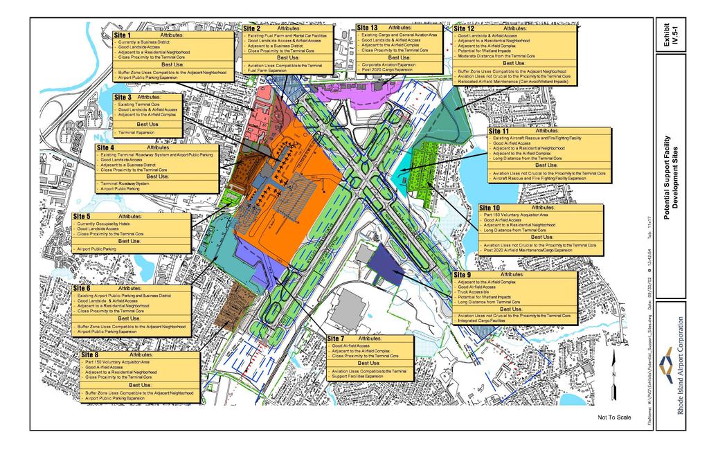
75