04 ALA /6.7. Vicinity Map
|
|
|
- Sharon O’Neal’
- 5 years ago
- Views:
Transcription


1
2 04 ALA /6.7
3 04 ALA /6.7 Vicinity Map Note: I-80 is designated as an east-west freeway. Gilman Street is referred to as a northsouth urban arterial for the remainder of the report.


4
5 04 ALA /6.7 Table of Contents Contents 1. INTRODUCTION BACKGROUND PURPOSE AND NEED... 3 Purpose... 3 Need TRAFFIC ENGINEERING PERFORMANCE ASSESSMENT Preliminary Assessment and Findings Summary of Traffic Signal Operation Analysis and Findings Summary of Roundabout Operation Analysis and Findings Scope of Future Traffic Engineering and Studies, Activities and Task DEFICIENCIES Existing Freeway and Ramp Operation Deficiencies Local Roadway and Intersection Operation Deficiencies Existing Railroad Conditions Traffic Accident Data and Safety Analysis Secondary Deficiencies CORRIDOR AND SYSTEM COORDINATION Corridor Overview State Planning Regional Planning Local Planning ALTERNATIVES Design Standards Risk Assessment Storm Water Management Complete Street and Americans with Disabilities Act (ADA) of 1990 Compliance Constructability Life cycle cost analysis (LCCA) Highway Planting RIGHT-OF-WAY Utilities: Railroad: STAKEHOLDER INVOLVEMENT ENVIRONMENTAL DETERMINATION/DOCUMENT Summary Statement for PSR or PSR-PDS Land Use Growth Farmlands/Timberlands Community Impacts Visual/Aesthetics Cultural Resources... 34
6 04 ALA / Hydrology and Floodplain Water Quality and Storm Water Runoff Geology, Soils, Seismic and Topography Paleontology Hazardous Waste/Materials Air Quality Noise and Vibration Energy and Climate Change Biological Environment Cumulative Impacts Context Sensitive Solutions FUNDING SCHEDULE RISKS FHWA COORDINATION PROJECT REVIEWS PROJECT PERSONNEL ATTACHMENTS List of Attachments A. Project Location Map B. Schematic Maps of the Study Alternatives C. Typical Cross Sections D. Capital Outlay Project Estimate E. Preliminary Environmental Analysis Report (PEAR) Under Separate Cover F. Right-of-way Conceptual Cost Estimate Component G. Risk Register H. Storm Water Document Under Separate Cover I. Traffic Engineering Performance Assessment J. Existing Utility Plans K. Roundabout Design Memorandum L. Transportation Planning Scoping Information Sheet M. PSR-PDS Survey Needs Questionnaire N. Division of Engineering Services PSR-PDS Scoping Checklist O. Design Scoping Index P. Quality Management Plan
7 04 ALA / INTRODUCTION Project Description: The project proposes to improve traffic, pedestrian, and bicycle operations at the Interstate 80 (I-80) / Gilman Street interchange in Berkeley in Alameda County. The existing intersection controls, roadway geometry, and the high volumes of local and regional traffic on Gilman Street result in poor traffic operation at and near the interchange. Proposed project components include reconfiguration of I-80 ramps and ramp intersections, and reconstruction of Gilman Street from north of West Frontage Road to south of 2 nd Street. There is no freeway mainline improvement identified for the project. Currently, four (4) project alternatives are being studied: No build Build Alternative 1: Signalized Intersection Build Alternative 2: Roundabouts Intersection Build Alternative 3: Roundabouts Intersection with bypass ramps In addition to the proposed roadway improvements, each build alternative provides at-grade pedestrian and bicycle improvements to enhance pedestrian connections and promote regional bicycle network continuity. The Alameda County Transportation Commission (Alameda CTC) and the City of Berkeley have outlined $1.06 million of funding for this project, including $0.83 million in federal earmarks, through the PA/ED phase. Capital funding of the project has not been established to date, but is proposed in the future 2014 Alameda CTC Transportation Expenditure Plan (TEP). The project area is bounded by a mix of industrial, commercial and recreational developments. The existing off-ramps and on-ramps and their intersections are located within California Department of Transportation s (Caltrans) right-of-way. The segments of Gilman Street north and south of the ramp intersections fall within the City of Berkeley s right-of-way limits. Interstate 80 (I-80) is a transcontinental east-west freeway. This segment of freeway extends from San Francisco to Sacramento. I-80 shares the same designation as I-580 through the project area with four to five general purpose travel lanes and one High Occupancy Vehicle lane in each direction of travel. Gilman Street is an east-west arterial that extends from Buchanan Street Extension to the west and Hopkins Street to the east. Gilman Street is a major local truck and auto route for accessing the freeway. Within the vicinity of the project, Gilman Street features four lanes of travel (two lanes in each direction) between Buchanan Street Extension and 2nd Street, and two lanes of travel east of 2nd Street. Gilman Street provides primary access to Golden Gate Fields, the Tom Bates Recreational Complex and the waterfront shoreline areas. For the remainder of this report, project north (rather than true north) is assumed to follow Gilman Street. Therefore, Gilman Street will be referred to as a north-south roadway while I-80 is designated as an east-west freeway. 1

8 04 ALA /6.7 Project Limits 04-ALA-80, Post Mile 6.5/6.7 Number of Alternatives Four (including No-Build Alternative) Current Capital Outlay Support $190,000 to $1,157,000 (Excluding Caltrans Estimate for PA/ED Support Cost of $900,000) Current Capital Outlay $1,450,000 to $8,896,000 Construction Cost Range Current Capital Outlay Right-of- $1,180,000 Way Cost Range Funding Source Federal and Local Funds Type of Facility 10-lane Freeway and Local Street Number of Structures None Anticipated Environmental Initial Study (IS)/Environmental Assessment (EA) Determination or Document Leading to an Mitigated Negative Declaration (MND)/ Finding of No Significant Impact (FONSI) Legal Description In Alameda County in Berkeley from 0.7 Mile East of University Avenue Overcrossing to 0.5 Mile West of Buchanan Street Undercrossing Project Development Category Category 3 2. BACKGROUND Over the years, the City of Berkeley has completed numerous studies to identify the improvement needs for Gilman Street in the vicinity of the I-80 interchange. A combination of freeway congestion, inefficient roadway geometries, increased rail traffic and changes in land use contribute to the heavy traffic congestion in the project area. The need for Gilman Street Interchange improvements was identified early as 1998 by the City of Berkeley. The segment of I-80 from the San Francisco- Oakland Bay Bridge Toll Plaza to the Carquinez Bridge through the Gilman Street interchange is considered as one of the most congested freeway segments in the San Francisco Bay Area. The Union Pacific railroad track crosses Gilman Street at 3 rd Street, two blocks from the I-80/Gilman Street ramp intersections. The increase in rail traffic impedes local traffic circulation, and causes delays at the Gilman Street and 3 rd Street at-grade crossing. In recent years, land use in west Berkeley and its surrounding areas has changed significantly. The expansion of the City s development to the north generates additional traffic accessing the I-80 freeway through Gilman Street. However, the existing five-leg and six-leg stop-controlled intersections at the interchange cannot efficiently clear the traffic movements resulting in substantial delay in the project area. The West Berkley Parking and Circulation Study was performed in 1998 and focused on parking and circulation deficiencies in the area bounded by Cedar Street, Sixth Street, University Avenue and Eastshore Highway (collectively known as the West Berkeley Redevelopment Area). One of the action items from the Circulation Study was to outline possible solutions to improve traffic flow at the Eastshore Highway and West Frontage Road in the interchange area. To address the safety and operational issues, the Gilman Street Interchange Improvement Study (2005) further analyzed the roadway circulation and provided recommendations for interchange reconfiguration. Results of the study indicated a dual roundabout design with a connecting segment between the I-80/Gilman Street intersections would provide the most benefit. It was considered the most viable alternative to improve traffic flow while meeting safety, accessibility and mobility needs. Several subsequent studies also supported these findings. 2
9 04 ALA /6.7 A draft Project Study Report (PSR) was prepared and submitted to Caltrans in November The draft PSR suggested that the dual roundabout design was the most viable solution to achieve acceptable levels of service without any modifications to freeway structures. Caltrans review called for additional analyses to address the operational issues. In 2006, the I-80/Gilman Street Interchange project was listed in the Alameda Countywide Transportation Plan and Metropolitan Transportation Commission s 2030 Regional Transportation Plan for $1.5 million funding. In 2009, the City of Berkeley issued the West Berkeley Circulation Master Plan Report of 2009 (Master Plan) that covered the transportation network and operating conditions in the west Berkeley area including the I-80 Gilman Street interchange. The Master Plan highlighted Gilman Street interchange as an area of concern. The Gilman Street interchange and adjacent frontage roads experienced congestion and delay during all periods of the day and all days of the week. The at-grade rail crossing near the interchange also added to vehicle queuing when rail activity blocked the roadway. The Master Plan also reviewed bicycle and pedestrian elements including the provision of a grade-separated bicycle and pedestrian path. The Alameda County Transportation Commission (Alameda CTC) has been working in partnership with the City of Berkeley to re-initiate the PSR effort since the year In support of the PSR study, the Alameda CTC approved budget in October 2011 to fund the Project Initiation Document (PID) and entered a PID review agreement with Caltrans in March 2012 for project oversight. The project s Purpose and Need statement was established and has been reviewed by various project s stakeholders, including Alameda CTC, City of Berkeley and Caltrans. In November 2012, both Caltrans Office of Advance Planning and Office of Environmental Analysis concurred with the Purpose and Need statement. Pedestrian and bicycle elements, such as an at-grade multi-use path and crossings were incorporated into the roundabout design. To address the safety of bicyclists and pedestrians across the roundabout, several bike and pedestrian underpass concepts and alignments were developed. In May 2013, Berkeley Transportation Commission reviewed the grade separation concepts for bicycle and pedestrian crossing the Gilman interchange and had serious reservations about perceived comfort and safety below grade. Because of safety concerns and the presence of underground utility conflicts and safety concerns, the underpass concepts were precluded from further study. 3. PURPOSE AND NEED Purpose Simplify and improve navigation and traffic operations on Gilman Street between the West Frontage Road and 2nd Street through the I-80 interchange so that congestion is reduced, queues are shortened, and merging and turn conflicts are minimized; Improve mobility in the Gilman Street corridor; Improve safety at Gilman Street intersections; Improve the local and regional bicycle and pedestrian facilities through the I-80/Gilman Street interchange for the bikes/pedestrians traveling between the Bay Trail and Northern Berkeley; Create a Gateway into North Berkeley. Need Nonstandard spacing between I-80 ramp intersections and frontage roads combined with free- 3
10 04 ALA /6.7 flow traffic on Gilman Street without turn channelization creates poor intersection operations due to short weaving lengths, left turn storage in through lanes, and complex vehicle navigation through multiple points of conflict; Existing and future poor Level of Service (LOS) at the I-80 ramp intersections and Eastshore Highway intersections with Gilman Street during weekday and weekend peak hours due to stop-controlled intersections; Existing vehicle queue spillback from the I-80/Gilman Street ramp intersections onto the freeway off-ramps, especially in the westbound I-80 direction; Gap in the local and regional bikeway system exists on Gilman Street between the Class II facility east of 2 nd Street and the Class I Bay Trail facility. 4. TRAFFIC ENGINEERING PERFORMANCE ASSESSMENT A Traffic Engineering Performance Assessment (TEPA) was completed for the project. The intent of the TEPA is to identify existing deficiencies and their causes, and recommend future implementations to improve overall traffic conditions. The TEPA analysis focuses on localized traffic issues based on readily available information and data; it is assumed that a larger scale traffic engineering study with more detailed traffic analyses will be performed during the Project Approval and Environmental Document (PA/ED) phase. The following paragraphs provide a summary of the preliminary assessment and key findings of the TEPA. 4.1 Preliminary Assessment and Findings Traffic congestion and operational issues associated with the I-80 on- and off-ramps, combined with the close proximity of two-directional frontage roads; create a primary traffic issue in the City. The six-leg stop-controlled intersections at the eastbound I-80 ramps and Eastshore Highway, and the five-leg intersection at the westbound I-80 ramps and West Frontage Road are complex, confusing, and encourage potentially unsafe traffic movements. Currently, only stop-control signs are implemented on the minor approaches/streets that intersect with Gilman Street within the vicinity of the project, including the I-80 eastbound and westbound ramps, and the two frontage roads (West Frontage Road and Eastshore Highway) immediately north and south of the interchange. Due to the significant volume of vehicles entering Gilman Street from the minor approaches during peak hours of travel, there are significant delays at these intersections. The ramp and frontage road intersections operate in poor LOS as described in Section 5 Deficiencies of this report. It is anticipated that this situation will worsen as regional traffic is projected to grow. The existing five- and six-leg intersections make it difficult for bicyclists and pedestrian to traverse through the interchange area. In addition to the traffic movements, the TEPA study also evaluated potential bicycle and pedestrian element that would improve the overall system safety. In the effort to address these deficiencies, previous traffic studies were conducted for the City of Berkeley, including the Gilman Street Interchange Improvements Draft Project Study Report (2005), and the West Berkeley Circulation Master Plan Report (2009). Given the complex traffic movements, these studies indicated implementation of traffic signals and construction of roundabout intersections would yield the most promising results. This TEPA (built upon the previous assumptions and findings) further evaluates these design alternatives through supplemental traffic studies. 4
11 04 ALA / Summary of Traffic Signal Operation Analysis and Findings Traffic signal operation analyses for existing and future traffic conditions were performed for the two ramp intersections using 2011 traffic volumes as the base case scenario. The analyses assumed the future roadway and intersections geometries remain similar to existing, with minor re-striping to provide additional storage. The resulted LOS and delay were summarized in Table 1 and 2 below. Table 1: Signalized Intersection Operational Analysis Results at West I-80 Ramp Terminal AM Peak Hour PM Peak Hour Approach Level of Service Volume to Capacity Ratio* Delay* (sec) 95 th Percentile Queue (feet) Level of Service Volume to Capacity Ratio* Delay* (sec) 95 th Percentile Queue (feet) 2011 Existing Conditions Build Alternative 1 Southbound Gilman St C C I 80 Westbound Offramp D F Northbound Gilman St C E I 80 West Frontage Road A F Build Alternative 1 Southbound Gilman St C D I 80 Westbound Offramp E F Northbound Gilman St C E I 80 West Frontage Road A F Build Alternative 1 Southbound Gilman St C D I 80 Westbound Offramp E F Northbound Gilman St C F I 80 West Frontage Road A F * Delay in seconds 5
12 04 ALA /6.7 Table 2: Signalized Intersection Operational Analysis Results at East I-80 Ramp Terminal AM Peak Hour PM Peak Hour Approach Level of Service Volume to Capacity Ratio* Delay* (sec) 95 th Percentile Queue (feet) Level of Service Volume to Capacity Ratio* Delay* (sec) 95 th Percentile Queue (feet) 2011 Existing Conditions Build Alternative 1 I 80 Eastbound Off ramp D F Eastbound Eastshore Hwy C E Northbound Gilman St E F Westbound Eastshore Hwy C D Southbound Gilman St A C Build Alternative 1 I 80 Eastbound Off ramp F C Eastbound Eastshore Hwy D F Northbound Gilman St F F Westbound Eastshore Hwy D E Southbound Gilman St A C Build Alternative 1 I 80 Eastbound Off ramp F F Eastbound Eastshore Hwy D F Northbound Gilman St F F Westbound Eastshore Hwy D F Southbound Gilman St A D * Delay in seconds 6
13 04 ALA /6.7 Tables 1 and 2 summarized the traffic signal operations level of service for the study years. As shown in Tables 1A and 1B, the study intersections operated at a reduced LOS during the PM peak hour (LOS E) for the existing condition (year 2011). Due to the projected traffic growth in year 2030 and 2040, the signalized intersections will experience further delays and operate between LOS D to LOS F. The primary cause of delay on the west ramp terminal intersection is due to the large volumes of traffic movements from the westbound off-ramp turning into West Frontage Road, and from eastbound traffic on West Frontage Road to Gilman Street. To allow for safe operation of the fiveand six-leg intersections, traffic movements in two opposing approaches must occur consecutively rather than concurrently. The requirement to have protected movements in split phasing at all approaches requires extensive signal cycle and resulted in significant traffic delay. 4.3 Summary of Roundabout Operation Analysis and Findings Two multilane roundabout design alternatives were developed and evaluated for the existing 2011, and future 2030 and 2040 weekday peak hour conditions. Roundabout intersection designs under Build Alternative 2 provide connections to all existing intersecting streets. Build Alternative 3 includes two by-pass ramps that directly connect the westbound roundabout to I-80 eastbound onramp and eastbound roundabout to I-80 westbound on-ramp. These exclusive connections reduce the volume of traffic movements traversing between and through the circulatory roadways. Results of the operation analysis for the I-80 eastbound and westbound roundabout intersections under Build Alternative 2 and 3 are shown in Table 3 and 4. As summarized in Table 3 and 4, all roundabout approaches under Build Alternative 2 are forecasted to operate at LOS C or better under the base case scenario (2011) except for westbound Eastshore Highway during the PM peak. Build Alternative 2 does not provide adequate capacity to handle the year 2030 and 2040 eastbound West Frontage Road, northbound Gilman Street and westbound Eastshore Highway traffic during the weekday PM peak hours; and the year 2040 westbound offramp traffic during the weekday AM peak. To mitigate this, additional roadway capacity must be provided. With the addition of two bypass ramps, the roundabout intersections would be able to operate in acceptable LOS under Build Alternative 3. 7
14 04 ALA /6.7 Table 3: Roundabout Operational Analysis Results at West I-80 Ramp Terminal Approach Southbound Gilman Street I 80 Westbound Offramp Northbound Gilman Street Level of Service Volume to Capacity Ratio* AM Peak Hour Delay* (sec) 95 th Percentile Queue (feet) Level of Service 2011 Existing Conditions Build Alternative 2 PM Peak Hour Volume to Capacity Ratio* Delay* (sec) 95 th Percentile Queue (feet) A A C A C C West Frontage Road A C Southbound Gilman Street I 80 Westbound Offramp Northbound Gilman Street 2030 Build Alternative 2 A A D B D B West Frontage Road A F >1.0* Southbound Gilman Street I 80 Westbound Offramp Northbound Gilman Street 2040 Build Alternative 2 A A F > ,125 B D C West Frontage Road B F >1.0 >120 >1,500 Southbound Gilman Street I 80 Westbound Offramp Northbound Gilman Street 2040 Build Alternative 3 A A C A C A West Frontage Road A D * v/c ratio is calculated as
15 04 ALA /6.7 Table 4: Operational Analysis Results at East I-80 Ramp Terminal Intersections AM Peak Hour PM Peak Hour Approach Level of Service Volume to Capacity Ratio* Delay* (sec) 95 th Percentile Queue (feet) Level of Service Volume to Capacity Ratio* Delay* (sec) 95 th Percentile Queue (feet) 2011 Existing Conditions Build Alternative 2 I 80 Eastbound Off ramp B B Eastbound Eastshore Hwy Northbound Gilman Street Westbound Eastshore Hwy Southbound Gilman Street B C A D C F >1.0 > A A Build Alternative 2 I 80 Eastbound Off ramp C B Eastbound Eastshore Hwy Northbound Gilman Street Westbound Eastshore Hwy Southbound Gilman Street A B A F >1.0* B F B A Build Alternative 2 I 80 Eastbound Off ramp E C Eastbound Eastshore Hwy Northbound Gilman Street Westbound Eastshore Hwy Southbound Gilman Street A C A F >1.0 >120 1,325 B F C A Build Alternative 3 I 80 Eastbound Off ramp D A Eastbound Eastshore Hwy B A Northbound Gilman Street A B Westbound Eastshore Hwy C B * v/c ratio is calculated as
16 04 ALA / Scope of Future Traffic Engineering and Studies, Activities and Task The purpose of the TEPA process is to develop an initial traffic scope of work for more detailed traffic analyses to be completed during the PA&ED phase. The following are identified as the scope of future traffic engineering studies: Project Study Limits: The limits for the freeway and ramp traffic operations include I-80 (east-west freeway) from east of Buchanan Street to west of University Avenue. All the ramps within the limits including I-580, Cleveland Ave, Buchanan Street, Gilman Street, and University Avenue will be evaluated with each build and no-build alternative. The limits for arterial traffic analysis include Gilman Street from I-80 interchange to San Pablo Avenue, traffic interchanges at Cleveland Avenue, Buchanan Street, Gilman Street, and University Avenue. Traffic Data Collection: Obtain most current vehicle, pedestrian and bicycle traffic counts (weekday and weekend daily, and morning and afternoon peak hours) on the existing facility. The data collection will include freeway mainline, ramp and cross-street daily traffic volumes, peak hour traffic volumes at intersections and interchanges, pedestrian and bicycle counts on Gilman Street. The traffic data collection will include origin-destination survey to determine the existing complex movements that occur on Gilman Street between the West Frontage Road, Traffic Interchange and Eastshore Hwy. Traffic Forecasting: Develop future design year forecasting on I-80, I-580 freeways, ramps and local streets in the project study limits. Traffic Safety Analysis: A detailed crash/safety analysis will be included in the traffic study. It is expected that the overall safety of the area will benefit from the intersection improvements by reducing traffic congestion. Freeway and Ramp Capacity and Operational Analysis: Detailed operational analysis will be completed for existing conditions, and design year conditions for each alternative with and without the project, and any proposed project construction phasing. At a minimum, the study scope will include evaluation of freeway traffic operations at the traffic interchange with exit ramp and entrance ramp and interchange improvements and ramp metering operations with each build and no build alternative. With respect to the ramp metering, the freeway traffic operations evaluation will include an estimate of queue storage needs under peak conditions and potential additional analysis work to adjust ramp meter operation, if necessary. Freeway and ramps traffic operations on I-80 between I- 580 and University Avenue will also be reviewed. Network Analysis: The traffic study will include network analysis with detailed freeway operational analysis within the project limits considering the short spacing of existing ramp terminals. Intersection Capacity and Operational Analysis: In addition to the signalized and roundabout intersection alternatives discussed in the TEPA, the PA/ED traffic analysis scope includes evaluation of additional alternatives including, but not limited to, combining the frontage roads with the freeway ramp. The traffic analysis will evaluate the impacts to the local street network on Gilman Street from I-80 interchange to San Pablo Avenue considering the close proximity of these intersections to the traffic interchange. The traffic analysis will also evaluate the impacts on I-80 traffic interchanges east and west of Gilman Street to identify potential bottlenecks and measures. Intersection Control Evaluation (ICE): An ICE will be prepared to evaluate the effectiveness of traffic signal and yield-controlled roundabout proposals as compared to the existing unsignalized operations once additional traffic counts and forecasting data are available during the PA/ED phase. Traffic Impacts during Construction: The traffic impacts during construction for each alternative will be evaluated and mitigated. Special attention will be paid to the performance of non-standard geometric features, if any. 10
17 04 ALA /6.7 Pedestrian and Bicycles Improvement Analysis: Additional pedestrian and bicycle measures such as the addition of shared-use paths will also be evaluated for each alternative. Determine Traffic Index for Pavement Design: Determine the Traffic Index for Pavement Design for ramps, and Gilman Street. The PA/ED traffic study will also evaluate some focused areas for the traffic signal and roundabout alternatives: Traffic Signal Alternative 1. The traffic signal options do not appear to be an improvement over the current stop-controlled conditions. Reconfigurations of the ramps/frontage roads will accompany the signal improvements. At a minimum, the proposed design and traffic study in the next project phase will review the following additional roadway features: Westbound Ramp Intersection: Westbound I-80 off-ramp right turn lane to northbound Gilman Street Northbound left turn lane on Gilman Street under the I-80 Structure (10-foot lane) One through lane for southbound Gilman Street through traffic (10-foot lane) Eastbound Ramp Intersection: Right turn lane pocket on Northbound Gilman Street Left turn lane on Southbound Gilman Street under I-80 structure Two southbound through lanes for Gilman Street (10-foot lanes) Provision of five-lanes under the I-80 Structure (measured approximately 56 feet under the existing structure) 2. The option of converting the existing two-way frontage roads to one-way streets will also be evaluated. This will allow for traditional merging of the on/off-ramps onto the frontage roads and simplify the interchange to a standard configuration. It also removes the number of conflicting movements. 3. The existing queue jumping movements that happen from westbound off-ramp to I-80 frontage road on west ramp terminal and the movement from eastbound I-80 frontage road right turn to Gilman Street and left turn onto I-80 eastbound on-ramp was assumed to occur during the future year traffic conditions. It is anticipated that the future I-80 Ramp Metering project will discourage queue jumping of drivers using the West Frontage Road. Additional study to review the queue jumping movements is recommended. Roundabout Alternative If one of the roundabout alternatives is advanced, future traffic engineering activities will include: 1. Development of a conceptual signing plan for the roundabout alternatives. The proposed multilane roundabouts will have exclusive turn lanes that lead to various exits. Appropriate pavement markings will be installed at the roundabout entrances and circulatory roadway to provide guidance. To avoid confusion and lane changing within the circulatory roadway, it is important to position drivers in advance of each movement. Roadside signs and advance overhead guide signs will be installed at the entrances to a roundabout to help drivers determine which exit to take and to get into the correct lane on approaching a roundabout. Additional signing will also be implemented to increase drivers awareness of the bypass ramps under Build Alternative 3. Alternate route signs will also be provided to guide drivers in the event of a missed 11
18 04 ALA /6.7 approach/route. 2. Further evaluation of bypass on-ramp performance with respect to ramp metering and High Occupancy Vehicle (HOV) lane. A bypass ramp will be connected to eastbound on-ramp as a third lane under Build Alternative 3. The performance of the connection will be further evaluated against ramp metering. If an HOV lane at the ramp meter is included, potential effects of lane merge will be considered. 3. Local traffic circulation as a result of closing access. To accommodate the construction of bypass ramp for Build Alternative 3, westerly access from Eastshore Highway to Gilman Street will be permanently closed. Traffic will be redirected to an alternate route. There is a potential need to convert 2 nd Street from one-way to two-way between Gilman Street and Harrison Street. Change of traffic circulation and access would have potential impacts on intersection performance and signalization. The findings of the PA&ED traffic analysis will be documented in a Final Traffic Operations Report (TOR) which will be used to select the preferred alternative and support the project purpose and need. A preliminary Traffic Management Plan will be developed with the PA&ED process. It may be determined that some of the aspects mentioned in this section may be modified or omitted upon concurrence with Caltrans staff. 5. DEFICIENCIES The I-80 Gilman Street has long been an area of concern by the City of Berkeley due to heavy congestion and substantial delays. To address the existing problems, an Existing Conditions Report (ECR) was prepared in August 2011 and focused on identifying existing deficiencies at the interchange area. The report highlighted three (3) primary deficiencies: freeway and ramp operation deficiencies, local roadway and intersection operation deficiencies, and constraints caused by the 3 rd Street/Gilman Street at-grade railroad crossing. Congested freeway conditions, inefficient and complex roadway and intersections configurations, and proximity to the rail at-grade crossing are the main causes of the deficiencies. 5.1 Existing Freeway and Ramp Operation Deficiencies An analysis on existing regional freeway and ramp operations was conducted as part of the ECR. The analysis included study of freeway facilities along I-80 between the Buchanan Street interchange to the north and the University Avenue interchange to the south of the Gilman Street interchange (see Attachment A). The study indicates all eastbound freeway mainline segments within the study area operate at an unacceptable Level of Service F (LOS F) during the weekday PM peak hours and weekend peak hours, representing a breakdown condition. For the westbound direction of travel, the freeway mainline segments operate at an unacceptable LOS F during the weekday AM peak. The westbound segment from Buchanan Street to University Avenue also operates between LOS D and F in the weekend peak. Table 5 and 6 summarize the results of the freeway operations analysis. Table 5: Freeway Mainline Level of Service and Density (Eastbound) Freeway Segment Weekday AM Peak Hour Weekday PM Peak Hour Saturday Peak Hour Density LOS Density LOS Density LOS University Ave. to Gilman St D >67.0 F >67.0 F Gilman St. to Buchanan St D >67.0 F >67.0 F Source: Parsons Brinckerhoff, Note: Unacceptable level of service indicated in bold. 12
19 04 ALA /6.7 Table 6: Freeway Mainline Level of Service and Density (Westbound) Freeway Segment Weekday AM Peak Hour Weekday PM Peak Hour Saturday Peak Hour Density LOS Density LOS Density LOS Buchanan St. to Gilman St. >67.0 F 28.0 C 40.0 D Gilman St. to University Ave. >67.0 F 32.0 D >67.0 F Source: Parsons Brinckerhoff, Note: Unacceptable level of service indicated in bold. The results of the freeway operation analysis are generally consistent with the data provided by the Alameda CTC s Level of Service Monitoring Report. Ramp operation analysis also shows an unacceptable LOS E and LOS F at selective weaving, merging and diverging sections between subsequent on- and off-ramps in the study area. The ramp LOS during weekday and weekend peak hours is shown in the tables below. Table 7: Freeway Ramp Level of Service and Density (Eastbound) Ramp Weekday AM Peak Hour Weekday PM Peak Hour Saturday Peak Hour LOS LOS LOS Diverge Section at University Ave. E E F Merge Section at University Ave. and Diverge Section at Gilman St. D F F Weaving Section at Gilman St. and Buchanan St. D F E Source; Parsons Brinckerhoff, Notes: (1) Unacceptable level of service indicated in bold. (2) 1985 HCM methodology does not apply. Table 8: Freeway Ramp Level of Service and Density (Westbound) Weekday PM Peak Saturday Peak Weekday AM Peak Hour Ramp Hour Hour LOS LOS LOS Weaving Section at Gilman St. and Buchanan St. D D E Merge Section at Gilman St. and Diverge Section at University Ave. F D F Merge Section at University Ave. F D F Source: Parsons Brinckerhoff, Notes: Unacceptable level of service indicated in bold. Data collected by Caltrans 2007/2008 travel speed surveys indicated the average weekday travel speeds on eastbound I-80 over Gilman Street are recorded at 63 miles per hour (mph) in morning commute hours and 37 mph in the evening commute hours. The average weekday travel speed on westbound I-80 at Gilman Street Interchange ranges from 30 mph (PM peak hours) to 41 mph (AM peak hours). 5.2 Local Roadway and Intersection Operation Deficiencies The local roadway and intersections pose various unique operational deficiencies. The main overlying deficiency is that the existing Gilman Street intersections use stop control on all but the northbound and southbound approaches. Due to the significant volume of vehicles entering the 13
20 04 ALA /6.7 facility at stop controlled approaches, there is unnecessary delay being created. The number of conflict points for the stop control movements is undesirably high, thus creating an operational concern for vehicular and pedestrian traffic along this facility. Roadway operation analysis was conducted for intersections on Gilman Street between West Frontage Road and 6 th Street. The study evaluated the effectiveness and capacity of the existing system based on intersection LOS analysis and queuing conditions. As shown in Table 9, all seven (7) study intersections operate at unacceptable condition with LOS exceeding level D. Table 9: Intersection Levels of Service and Delay Intersection Gilman St.& West Frontage Rd / Private Lot Gilman St. & I-80 WB Ramps Gilman St.& I-80 EB Ramps Gilman St./ Eastshore Highway Control Type Weekday AM Peak Hour Weekday PM Peak Hour Saturday Peak Hour LOS Delay LOS Delay LOS Delay TWSC > 50.0 F > 50.0 F > 50.0 F TWSC > 50.0 F > 50.0 F > 50.0 F TWSC 20.5 C > 50.0 F 36.4 E TWSC > 50.0 F > 50.0 F > 50.0 F 5 Gilman St. / 2nd St. TWSC 44.6 E > 50.0 F > 50.0 F 6 Gilman St. / 4th St. TWSC 43.3 E > 50.0 F > 50.0 F 7 Gilman St./ 5 th St. TWSC 43.3 E > 50.0 F > 50.0 F 8 Gilman St./ 6 th St. Signal 11.7 B 20.9 C 14.4 B Source: I-80 Gilman Interchange Project Existing Condition Report, Parsons Brinckerhoff, Notes: (1) Unacceptable level of service indicated in bold. (2) OWSC (one-way stop controlled), TWSC (two-way stop-controlled) results are for the worst approach delay. Signal, AWSC (all-way stopcontrolled) results are average delay. Substantial length of queues were observed in the queuing analysis at the I-80 westbound off-ramp to Gilman Street and along Eastshore Highway eastbound and westbound. The Synchro model estimated a queue length of 1950 feet at westbound off-ramp to Gilman Street during the weekday AM peak and the off-ramp reached its current capacity during the weekend peak hours. At the intersection of Gilman Street and Eastshore Highway, the Eastshore Highway eastbound lanes exceed their current capacity during the weekday PM peak and weekend peak hours. The Eastshore Highway westbound lanes also experience substantial delay during weekend peak with a queue length exceeding its capacity. The following traffic movements show substantial delay that exceeds capacity: I-80 westbound off-ramp left turn to Gilman Street (weekend) I-80 westbound off-ramp through movement to I-80 westbound (weekend) Eastshore Highway eastbound left turn to Gilman Street (weekday PM and weekend) Eastshore Highway westbound left turn to Gilman Street (weekend) 2 nd Street eastbound left turn to Gilman Street (weekend) The vehicle classification surveys conducted in December 2010 noted a high percentage (13%) of truck traffic on Gilman Street south of the West Frontage Road intersection. Trucks also utilize eastbound Eastshore Highway as a primary local access route. Truck traffic comprises 24% to 28% of total weekday daily traffic on Eastshore Highway between Cedar Street and Gilman Street, and 14
21 04 ALA /6.7 between Gilman Street and Harrison Street. 5.3 Existing Railroad Conditions The Union Pacific Railroad (UPRR) owns and maintains their railroad facility on 3 rd Street parallel to I-80, which is also known as the 3 rd Street Corridor. The 3 rd Street Corridor crosses Gilman Street at grade. Train operation affects the local traffic circulation. Vehicular queue lengths build up when the railroad gates are down for crossing trains. Approximately 44 passenger trains operated by Amtrak pass through the Gilman Street/3 rd Street intersection daily between 6:00 a.m. and 10:00 p.m. The second-largest freight railroad network, Burlington Northern Santa Fe (BNSF) also runs their freight trains through the project area throughout the day. It is estimated that a total of 30 BNSF and UPRR freight trains pass through the Berkeley area every day. The projected rail traffic will continue to rise. The existing dual tracks could support up to approximately 100 trains per day. 1 By 2030 a total of 30 new service trains could be added to the existing 3 rd Street Corridor. Summaries of existing passenger and freight train operations are provided in Table 10 and 11. Table 10: Existing Freight Train Operations Trains per day > 30 Trains per time of day Typical train length (average) Maximum timetable speed Typical speeds Growth rate in trains Varies 7,000 ft 70 mph 50 mph 3% per year Source: West Berkeley Circulation Master Plan, Wilbur Smith Associate, 2009; I-80 Gilman Interchange Project Existing Conditions Report, Parsons Brinckerhoff, 2011 Table 11: Existing Passenger Rail Operations Trains per day 44 Trains per time of day Typical train length (average) Maximum timetable speed Typical speeds Growth rate in trains 6 am to 10 pm 700 ft 79 mph mph Limited by UP Agreement Source: West Berkeley Circulation Master Plan, Wilbur Smith Associate, 2009; I-80 Gilman Interchange Project Existing Conditions Report, Parsons Brinckerhoff, Traffic Accident Data and Safety Analysis The accident and roadway records collected by California State s Traffic Accident Surveillance and Analysis System (TASAS) was compiled and analyzed by Caltrans for a three-year period, from January 1, 2009 to December 31, The TASAS Table B Selective Accident Rate Calculation 1 West Berkeley Circulation Master Plan Report, Wilbur Smith Associates,
22 04 ALA /6.7 provides data for fatal and injury motor vehicle accidents. Available accident details from the TASAS Selective Accident Retrieval (TSAR) database (such as the primary collision factors, types of collision and the roadway conditions when the accidents occurred) were also reviewed for the project area. A summary of the accident data was analyzed and is presented in Table 12. A total of 200 accidents with 39 injuries were reported on the mainline during the three-year study period. The total accident rate of 1.65 accidents per million vehicle miles (MVM) is higher than the statewide average of 1.08 accidents per MVM for similar types of facilities. The mainline fatality rate of accidents per MVM is also significantly higher than the statewide average of accidents per MVM. There were 33 accidents recorded on the I-80 Gilman on-ramps and off-ramps. As compared to the total of 26 accidents in the previous study period (January 1, 2008 to December 31, 2010), there was a net increase of 27%. When reviewing the ramp accident rates at the Gilman Street interchange, the westbound I-80 off-ramp to Gilman Street experienced higher accident rates than the statewide average. A total of 2.09 accidents per MVM were recorded at the off-ramp location, which is double the statewide average of 1.01 accidents per MVM. Table 12: Summary of Traffic Accident Data Location Description Tot Fat Inj F+I PM to I PM PM PM Accident Rates (Accidents Per Million Vehicle Miles) No of Accidents/Significance Actual Average Multi Veh Wet Dark Fat F+I Tot Fat F+I Tot Mainline I-80 WB On-ramp from Gilman Street I-80 EB Off-ramp to Gilman Street I-80 EB On-Ramp from Gilman Street I-80 WB Off-ramp to Gilman Street PM Abbreviations: Tot = Total Reported Accidents, Fat = Fatalities; Inj=Injuries; F+I = Fatalities plus Injuries; Multi Veh = Multiple Vehicle Source: California Department of Transportation TASAS Notes: Accident rates that are higher than the statewide average were indicated in bold. The 21 reported accidents at I-80 westbound off-ramp break down as follows: 12 involved rear-ended collisions, 1 involved hitting objects, 4 broadsides, 3 sideswipes and 1 head-on collision. The primary collision factor is speeding, accounting for 42.9% of the overall accident rates. Other collision factors include failure to yield (23.8%), driving under the influence of alcohol (9.5%) and other violations (19.0%). The majority of the accidents occurred in daytime under good weather conditions. The I-80 westbound off-ramp is one of the six intersections within the project area that is operating at an unacceptable condition (LOS F).The high percentage of rear-end collisions reflects the highly 16
23 04 ALA /6.7 congested ramp situation. This situation is anticipated to worsen considering the projected increase in traffic for the future no-build condition. With the installation of roundabouts under Build Alternative 2 and 3, the level of service at the location would be improved to acceptable levels; and hence, the number of accidents would likely to be reduced due to the improved traffic condition. In general, the project will bring benefit to the overall safety of the interchange area by reducing the traffic congestion for the Roundabout Alternatives. 5.5 Secondary Deficiencies Other geometric and right-of-way constraints that also limit the scope and scale of proposed improvements are: Existing infrastructure severely constrains the footprint of design. I-80 freeway structure abutments and columns restrict the possibility of expanding Gilman Street undercrossing to accommodate the future traffic need. The narrow right-of-way widths along the frontage roads limit the width of roadway expansion. On-street parking along the frontage roads must be preserved to the extent possible to minimize impact to the local business. This further restricts widening along the frontage roads. 6. CORRIDOR AND SYSTEM COORDINATION Alameda CTC has been working closely with the City of Berkeley in planning and coordinating the PSR-PDS preparation effort. In 2006, the I-80/Gilman Street Interchange project was listed in the Alameda Countywide Transportation Plan and Metropolitan Transportation Commission s 2030 Regional Transportation Plan for $1.5 million funding. The Metropolitan Transportation Commission is a Metropolitan Planning Organization and Regional Transportation Planning Agency which provide region planning, financing and coordinating effort for transportation improvements within the nine-county San Francisco Bay Area. This I-80 Gilman Street interchange project is also an integral part of the I-80 corridor improvements. The I-80 Integrated Corridor Mobility (I-80 ICM) project (which begin construction in fall 2012 and is expected to be completed in 2015) will implement ramp metering and incident management along I-80 from the San Francisco-Oakland Bay Bridge in Alameda County to the Carquinez Bridge in Contra Costa County through the Gilman Street interchange area. This project will employ ramp metering strategies that are compatible with the I-80 ICM project s overall objectives to reduce congestion, enhance travel time and improve safety. The West Berkeley Circulation Master Plan Report of 2009 (Master Plan) identified the I-80 Gilman Street interchange as an area of concern due to its all-time traffic delay and noted its need for improvements. This project is consistent with the City of Berkeley s Circulation Master Plan and General Plan. This project is consistent with planning efforts at all levels of government. Note that a new freeway maintenance agreement will be prepared to delineate maintenance responsibilities between the City of Berkeley and the State once a preferred alternative is selected. 6.1 Corridor Overview I-80 West is classified as an Interstate Freeway. The route is included in the State Highway System Interregional Road System and as part of the Surface Transportation Assistance Act national network. Caltrans District 4 recognizes I-80 West as a Bay Area Lifeline Route as well. 17
24 04 ALA /6.7 I-80 within the project limits (from post mile 6.53 to 8.04) is classified as a Landscaped Freeway and is subject to the California Outdoor Advertising Act and Regulations. 6.2 State Planning The 2013 Interregional Transportation Strategic Plan (ITSP) designates I-80 West a High Emphasis Interregional Route System (IRRS) route, a term that is phrase-specific to this plan, and represents a route that has high interregional importance from a statewide perspective. National Highway System Interstates included in this category are critically important to interregional travel and providing access to seaports, airports, rail yards, and national/international markets. The 2010 Corridor System Management Plan (CSMP) recommends a managed I-80 West corridor including an 8-12 lane freeway with bi-directional managed lanes that will be integrated with transit, arterial, incident and traveler information components supported by a traffic surveillance and monitoring system. Complete Streets Caltrans Deputy Directive 64-Revision (DD-64R) provides for the needs of travelers of all ages and abilities in all planning, programming, design, construction, operations, and maintenance activities on the State Highway System. The Department views all transportation improvements (new and retrofit) as opportunities to improve safety, access, and mobility for all travelers and recognizes bicycle, pedestrian, and transit modes as integral elements of the transportation system. California Transportation Plan (CTP) Senate Bill 391(SB 391) requires Caltrans to update its statewide California Transportation Plan (CTP) by December 31, 2015 and every five years thereafter. In addition it (SB 391) requires various transportation planning activities be taken by State and regional agencies, including preparation of a Sustainable Communities Strategy (SCS) by Metropolitan Planning Organizations (MPOs). Also, SB 391 establishes an on-going statewide transportation planning process within Caltrans that describes the multimodal system necessary to meet mobility and congestion management objectives that are consistent with the State s Greenhouse gas (GHG) emission limits and air pollution standards. Sustainable Communities Strategy (SB 375) Senate Bill 375 requires the Metropolitan Transportation Commission (MTC) region to meet State GHG emission targets for automobiles and light trucks for 2020 and MPO s must accurately account for the environmental benefits of more compact development and reduced vehicle miles traveled. The targets apply to the regions in the State covered by the 18 Metropolitan Planning Organizations. The current Regional Transportation Plan, Plan Bay Area, by MTC will include a Sustainable Community Strategy (SCS) as required by SB 375. The SCS lays out how GHG emissions reduction targets will be met for cars and light trucks. This will impact land use and travel patterns in the longrange planning horizon. Route Planning for Oversize and Overweight Vehicles Caltrans issues transportation permits to grant operating authority to vehicles exceeding the statutory limits for size and weight on the State Highway System. Permits are issued after the adequacy of vertical and horizontal clearance along the requested route is verified. Changes to clearance caused by the project (either temporarily or permanently), will affect restriction of oversize and overweight vehicles. The project needs to satisfy the reporting requirements related to the changes on State Highway System per Caltrans Deputy Directive DD-57, Route Information for Oversize and 18
25 04 ALA /6.7 Overweight Vehicles and the related Construction Bulletins. 6.3 Regional Planning MTC functions as both the Regional Transportation Planning Agency a State designation and, for federal purposes, as the region's Metropolitan Planning Organization (MPO). As such, it is responsible for regularly updating the Regional Transportation Plan, a comprehensive blueprint for the development of mass transit, highway, airport, seaport, railroad, bicycle and pedestrian facilities. MTC plays a major role in building regional consensus among the region s transit systems. State and federal laws have also given MTC an important role in financing Bay Area transportation improvements. MTC s 2013 Regional Transportation Plan (Plan Bay Area) lists programmed and planned projects (including ALA I-80 Corridor) within a 28-year planning horizon. Programmed projects in the project area include: RTP ID County Project Description ALA Implement I-80 Integrated Corridor Management (ICM) project operations and management ALA Convert I-80 HOV lanes to express lanes from State Route 4 to the Bay Bridge bypass lane in each direction ALA Reconstruct the Ashby Avenue interchange on I CC Modify I-80/Central Avenue interchange, includes connecting Pierce Street to San Mateo Street and relocating traffic signal to San Mateo/Central Avenue intersection CC Implement I-80 Integrated Corridor Mobility Project (includes the installation/upgrade of corridor management elements along the I-80 corridor (phase 1) and along parallel and connecting arterials (phase 2) to allow sharing of real-time traveler information among public agencies and the public 6.4 Local Planning Alameda CTC coordinates the countywide sales tax measure (Measure B, 2000), conducts transportation planning, delivers projects and manages various transportation programs. 7. ALTERNATIVES A total of four (4) alternatives were identified for the project including the No Build alternative. Schematic maps of the study alternatives and typical cross sections for the project alternatives are included in Attachment B and C. There is no right-of-way need anticipated for Build Alternative 1. Both Build Alternative 2 and 3 will require additional right-of-way. No Build Alternative The No Build Alternative is the existing I-80/Gilman Street Interchange with the improvements proposed by I-80 ICM. The ICM project proposes to convert one of the two existing mixed lanes on 19
26 04 ALA /6.7 the westbound Gilman Street on-ramp into an HOV lane. Build Alternative 1 Signalized Intersection Build Alternative 1 proposes to convert the existing stop control intersections into signalized intersections at ramp terminals and the adjacent frontage roads. The portion of Gilman Street undercrossing below the I-80 structure will be restriped to allow additional left turn storage lanes. The existing pedestrian and bicycle paths shall remain in-place. Build Alternative 2 Roundabout Intersection Build Alternative 2 requires the installation of two multi-lane roundabouts on Gilman Street at the I- 80 ramp terminals. Each roundabout will combine the ramp intersections with frontage road intersections to form one single roundabout intersection. All existing connections from minor streets will be maintained under this alternative. The westbound roundabout intersection consists of four approaching legs: northbound and southbound Gilman Street, West Frontage Road and I-80 westbound off-ramp. The eastbound roundabout intersection will include a total of five approaching legs from I-80 eastbound off-ramp, eastbound and westbound Eastshore Highway, and northbound and southbound Gilman Street. A pedestrian and bicyclist shared-use path will be constructed on the west side of the Gilman Street undercrossing. The shared-use path will terminate at the north and south limits of the project and adjoin the existing on-street bike lanes and sidewalk near the project s limits. Due to its inadequate roadway capacity to accommodate the year 2040 traffic, Build Alternative 2 is considered an interim design to address the year 2030 traffic needs. Option 2A The existing driveway entrance to the Golden Gate Fields (GGF) is located immediately adjacent to the westbound I-80 off-ramp at the end of the curb return. There is a minimum separation between the driveway entrance and the westbound ramp intersection. The construction of the roundabout will expand the ramp intersection to the north and further reduce this separation. With the proposed rightof-way to be established at the roundabout entrance and exit, the existing GGF driveway will likely encroach into the future Caltrans right-of-way (A detailed right-of-way discussion is included in Section 8 of this report). To establish the access control at the ramp intersection, Option 2A was developed to eliminate or relocate the existing driveway to outside of the proposed Caltrans right-ofway limit. As shown in Attachment B, roadway geometries for Option 2A are identical to Alternative 2 with the exception that the GGF s driveway connection to Gilman Street is removed or relocated. The proposal will be further evaluated with input from property owner and project stakeholders at the PA/ED phase and a more refined geometric layout will be developed. Build Alternative 3 Roundabout Intersection with bypass ramps Build Alternative 3 is similar to Alternative 2 with the addition of two bypass ramps. Alternative 3 proposes to construct two multi-lane roundabouts on Gilman Street at the I-80 ramp terminals. Each roundabout will combine the ramp intersections with frontage road intersections to form one single roundabout intersection. The two bypass ramps will be constructed underneath the I-80 freeway structure between the abutment walls and columns to provide direct connection between the roundabouts and the I-80 eastbound and westbound on-ramps. A total of four approaching legs and five departure legs will be accounted for in each roundabout. As compared to the other two build alternatives, the access from the east leg of Eastshore Highway to Gilman Street will be permanently closed to make room for the bypass ramp in this alternative. This segment of Eastshore Highway will become a cul-de-sac. Traffic is expected to use parallel roadways (such as 2 nd Street) to bypass the cul-de-sac and to continue on Eastshore Highway from the east to west side of Gilman Street, or vice versa. To accommodate the bypass traffic, a segment of 2 nd Street 20
27 04 ALA /6.7 between Gilman Street and Harrison Street would need to be converted from existing eastbound oneway traffic to two-way traffic. A pedestrian and bicyclist shared-use path will be constructed on the west side of the roadway between the Gilman Street undercrossing and bypass ramp. The shared-use path will terminate at the north and south limits of the project and adjoin the existing on-street bike lanes and sidewalk near the project limits. Build Alternative 3 will have adequate roadway capacity to handle the ultimate design year traffic (2040). Option 3A The existing driveway entrance to the Golden Gate Fields (GGF) is located immediately adjacent to the westbound I-80 off-ramp at the end of the off-ramp curb return. There is a minimum separation between the driveway entrance and the westbound ramp intersection. The construction of the roundabout will expand the ramp intersection to the north and further reduce the separation. With the proposed right-of-way to be established at the roundabout entrance and exit, the existing GGF driveway will likely encroach into the future Caltrans right-of-way (A detailed right-of-way discussion is included in Section 8 of this report). To establish access control at the ramp intersection, Option 3A was developed to eliminate or relocate the existing driveway to outside of the proposed Caltrans right-of-way limit. As shown in Attachment B, roadway geometries for Option 3A are identical to Alternative 3 with the exception that the GGF driveway connection to Gilman Street is removed or relocated. This proposal will be further evaluated with input from property owner and project stakeholders at the PA/ED phase and a more refined geometric layout will be developed. Other Studies/Rejected Alternatives Additional alternatives have been studied and reviewed by project stakeholders during the project alternative development, including the installation of pedestrian and bicycle shared-used paths on both sides of the Gilman Street undercrossing and construction of a pedestrian and bicyclist underpass and overpass. Concepts developed during the early project development phase called for pedestrian and bicycle shared-used paths on the east and west side of the Gilman Street undercrossing. Currently there is a significant volume of right-turn traffic entering the I-80 eastbound on-ramp from northbound Gilman Street at relatively high speed. It is difficult and unsafe for pedestrians and bicyclists to cross the ramp, especially during peak hours. Design review revealed that the non-motorists and motorists conflict at the eastbound on-ramp is intense for the future scenarios given the high volume of ramp traffic and the need for a two-lane crossing. Because there are few pedestrians and bicyclists currently using the east path to access the northeast side of the interchange where Golden Gate Fields is located, the east shared-use path was removed from design with project stakeholders and bicycle group s input. However, planning for redevelopment of Golden Gate Fields racetrack site is underway. The proposed alternative design includes additional right-of-way to accommodate future pedestrian and bicycle facilities on the east side of the Gilman Street undercrossing. In addition to the at-grade crossings, the City of Berkeley is evaluating other options to address the non-motorist needs, including the construction of a pedestrian and bicyclist underpass and overpass. The Berkeley Transportation Commission reviewed the underpass design and expressed concerns about the safety and comfort of the below grade concepts. Due to extensive underground utility conflicts and the required depth of underpass structures, the pedestrian and bicyclist underpass alternative was determined to be infeasible and was precluded from further study. The option for a pedestrian and bicyclists overpass is currently under evaluation by the City of Berkeley as a separate project. 21
28 04 ALA / Design Standards Risk Assessment Alternatives 1, 2 and 3 will require approval of the following potential nonstandard design features. The following tables outline the risk assessment associated with each nonstandard design standards. 22
29 04 ALA /6.7 Table 13: Potential Deviation from Design Standards Alternative 1,2, 3 Table 13.1 Advisory Design Standards Risk Assessment Probability of Design Standard Design from Highway Exception Design Manual Justification for Probability Rating Approval Tables 82.1A & (None, Low, 82.1B Medium, High,) Index 310.2: Outer Separation Urban and Mountainous Terrain High The outer separation between Eastshore Highway and the I-80 eastbound on-ramp will not meet the minimum of 26 feet from edge of traveled way to edge of traveled way in an urban area. The existing Eastshore Hwy is separated from the I-80 eastbound on-ramp by a 4 ft. to 5 ft. wide median. Due to the limited right-of-way, the proposed design will keep the separation similar to the existing condition. Request for design exception is likely required for this feature. 1 Index 504.3: Distance Between Ramp Intersections and Local Road Intersections High The distance between the existing Gilman Street/Eastshore Highway intersection and I-80 eastbound ramp intersection, and Gilman Street/West Frontage Road intersection and I- 80 westbound ramp intersection is approximately 40 to 50 feet. This does not meet the preferred minimum distance of 500 ft. between ramp intersection and local road intersection. The proposed signal improvement will maintain the existing intersection locations from which design exception is required. 1 Index 504.8: Access Control at Ramp Terminal High The existing driveway at the Golden Gate Field entrance is less than 100 feet from the curb return at the ramp terminal. The proposed signal improvement will maintain this existing driveway location from which design exception is required. 2, 3 Index (14) and 504.8: Access Control 2, 3 Index (14) and 504.8: Access Control Medium High The existing driveway at the Golden Gate Field entrance is less than 100 feet from the roundabout s inscribed circle diameter. The project proposes to relocate the existing driveway or close the driveway permanently as an option. If the driveway remains in its current location, design exception is required. The existing driveways located between Eastshore Highway and 2 nd Street is less than 100 feet from the roundabout s inscribed circle diameter. The existing driveways will remain after the completion of construction therefore design exception is required. 23
30 04 ALA /6.7 Alternative 3 Table 13.2 Mandatory Design Standards Risk Assessment Design Standard Probability of from Highway Design Exception Design Manual Approval (None, Justification for Probability Rating Tables 82.1A & Low, Medium, 82.1B High,) Index 101.1: Technical Reductions of Design Speed High The radius for the EB and WB bypass ramps do not provide the desired sight distance and lateral clearance to the bridge abutment for the specific ramp design speed. The bypass ramps will be constructed between the existing columns and abutment wall. Due to the limited spacing, the proposed design will not accommodate a larger turn radius. A technical speed reduction is required at the turns. 3 Index 203.1: Horizontal Alignment and Stopping Sight Distance Medium The clear distance from the centerline of the bypass ramp to the abutment wall may not meet the minimum sight distance required for the design speed. The bypass ramp will be constructed between the existing columns and abutment wall. Due to the limited available spacing, the proposed design will not accommodate a larger turn radius. 1 Index 301.1: Lane Width High The proposed lane width of 10 ft on the Gilman Street undercrossing between the two ramp intersections will not meet the minimum lane width of 11 ft. for conventional highway with posted speed of 40 mph or less. Preliminary traffic study indicated a minimum of 3 through lanes and 2 left-turn lanes (in both directions) is required for the signal alternative. Due to the presence of I-80 columns and the limited width of roadway underneath the I-80 structure, the Gilman Street can only accommodate five 10-feet lanes from which design exception is required. 2, 3 Index 302.1: Shoulder Width Medium Due to the presence of I-80 columns and the limited width of roadway underneath the I-80 structure, the usable shoulder width between the edge of traveled way and the face of column along the undercrossing for Alternative 2 and 3 is less than the minimum of 4 feet at selective locations. Depending on the outcome of additional traffic studies during PA/ED, request for design exception will be required if lane configurations remain as proposed. 24
31 04 ALA /6.7 2, 3 Index 307.2: Shoulder Standards for Two-lane Cross Sections for New Construction Medium The shoulder width on Gilman Street undercrossing is less than 8 feet for 2-way ADT over 400. Due to the presence of existing I-80 columns and the limited width underneath the I-80 structure, it can only accommodate shoulder width of 3 to 8 ft. Depending on the outcome of additional traffic studies during PA/ED, request for design exception will be required if lane configurations remain as proposed. 1 Index 308.1: Minimum Lane Width for City Streets and County Roads High The width for the outermost lanes on Gilman Street undercrossing will not meet the minimum width of 12 feet required for multilane local facility connecting to a freeway within an interchange. Preliminary traffic study indicated a minimum of 3 through lanes and 2 left-turn lanes (in both directions) is required for the signal alternative. Due to the presence of I-80 columns and the limited width of roadway underneath the I-80 structure, the Gilman Street can only accommodate five 10-feet lane from which design exception is required. 2,3 Index (3): Minimum Clearance to Objects High The minimum horizontal clearance of 4 feet cannot be provided where standard shoulder width is less than 4 ft. on Gilman Street undercrossing. Due to the presence of I-80 columns and the limited width underneath the I-80 structure, the required 4-ft. clearance to existing columns and concrete barrier cannot be achieved at selective locations. 1 Index 504.3(3): Location and Design of Ramp Intersection on Crossroads High The distance between the existing Gilman Street/Eastshore Highway intersection and I- 80 eastbound ramp intersection, and Gilman Street/ West Frontage Road intersection and I- 80 westbound ramp intersection is approximately 40 to 50 ft. This does not meet the required minimum distance of 400 ft. between ramp intersection and local road intersection. The proposed signal improvement will maintain the existing intersection locations from which design exception is required. 1 Index (14) and 504.8: Access Control Medium Existing driveway at the Golden Gate Field entrance is less than 50 feet from the inscribed circle diameter. The project proposes to relocate the existing driveway or close the driveway permanently as an option. If driveway remains in its current location, design exception is required. 25
32 04 ALA /6.7 In addition to the potential deviation from the above standards, the project requires to maintain any existing or install new HOV preferential lane at locations where ramp meter is implemented. A HOV preferential lane is typically placed on the left side of the ramp. However, the operational characteristics of the bypass ramp proposed for Alternative 3 may not allow its placement. Therefore, exception to the Traffic Operations policy for provision of HOV preferential lane at ramp meter locations may be deemed necessary for Alternative Storm Water Management The project is located adjacent to the San Francisco Bay. The Caltrans Statewide NPDES General Permit requires any non-caltrans project within State right-of-way that has direct discharge to surface water bodies and creates more than 5,000 square feet of new impervious surface on a non-highway facility is subject to treatment Best Management Practices (BMPs). Based on preliminary assessment, the project is required to consider permanent treatment BMPs. Temporary construction site BMPs will also be implemented to reduce the amount of storm water impact associated with construction activities. A Storm Water Data Report is prepared to identify the needs for storm water management. Measurements for avoiding or reducing potential storm water impacts are discussed in the Storm Water Data Report in Attachment H. 7.3 Complete Street and Americans with Disabilities Act (ADA) of 1990 Compliance The project not only improves the mobility and safety of motorists by reducing the level of congestion; it also provides numerous opportunities to enhance non-motorized mode of travel and aesthetic of the community. The pedestrian/bicyclist shared-use path (Class I) proposed by the roundabout alternatives provides a safe and continuous route that is compatible with the existing pedestrian and bicyclists network upstream and downstream of the project. The proposed Class I facility will accommodate bicyclists of various age and skill levels. Skilled bicyclists or commuters have an option to use the circulatory roadway or the adjacent Class I facility. Young or unskilled bicyclists are expected to use the Class I facility to travel through the roundabouts. In compliance with ADA and Code requirements, the project proposes to construct a continuous pedestrian facility (including curb ramps, crosswalk, sidewalk and path) that addresses mobility and accessibility needs. The project seeks to improve the safety of pedestrian crossings and to reduce the number of pedestrian-vehicle points of conflict. Due to the anticipated use by large-sized truck and AC Transit buses, the design will take into consideration special vehicle paths and other features. The selected design alternatives will address the needs for all travelers including pedestrian, bicycle, transit and other large-sized design vehicles while providing a safe network of complete streets that meets the Americans with Disabilities Act (ADA) of 1990 and Title 24 of the California Code of Regulations. 7.4 Constructability This project will not involve building of new structures. The constructability review performed today focus on evaluating the proposed design against the existing I-80 structures and substructures. Preliminary structural assessment using available as-built plans revealed that the top of existing footings for the I-80 columns and walls are located approximately 2 to 3 ft. below existing ground surface. The proposed Gilman Street will be reconstructed a minimum of 3 ft. from the face of existing columns. The bypass ramps for Build Alternative 3 will be located in approximately 2 to 8 ft. from the face of abutment walls. Construction of the bypass ramps will require deeper excavation along the abutment slopes to obtain adequate vertical clearance. Currently, a minimum of 15 ft 2 in. vertical clearance is available under the I-80 freeway structure. Any roadway fills above existing 26
33 04 ALA /6.7 ground which reduce the vertical clearance to below 15 feet, will trigger a design exception and require Headquarters Design Coordinator s review and approval. The potential design conflict with the I-80 underground structures will be carefully evaluated during the PA/ED phase. Use of full depth pavement may be more desirable to minimize the depth of cut and reduce the level of disturbance to existing structure. The project will cause temporary and permanent impact to on-street parking, access to freeway and local streets, as well as the entrance to Golden Gate Field. The proposed stage construction may include temporary roadway, lane and shoulder closures, and temporary detours. A Transportation Management Plan (TMP) will be developed at PA/ED phase, and implemented during construction to minimize and prevent delay and inconvenience to the traveling public. Preliminary impacts to vehicles, transit, pedestrian and bicycles access will be identified and outlined in the TMP during the PA/ED process. The TMP will also include detailed construction strategies that would mitigation such impacts. All existing Traffic Operations System (TOS) field elements and loop detectors within the project limits will be kept operational throughout all phases of construction. Any TOS element that may be affected by the project must be relocated, modified or fully replaced. Complete operational ramp metering system shall be installed for HOV bypass lane, including all underground and above ground equipment. 7.5 Life cycle cost analysis (LCCA) In review of the log of test borings the top 10 feet of surface soil materials are identified as very loose to loose sand and very soft organic clay (Bay mud). Preliminary geotechnical review estimated a subbase soil stability value (R value) of 5 at the site. Groundwater is encountered at approximately 7 to 8 feet below existing ground surface. LCCA is not required at this stage but will be conducted in the PA/ED phase. Due to the presence of existing shallow foundations and undesirable ground water and subsurface soil conditions, the subject LCCA will focus on the design of thin pavement sections that minimize existing structure impacts while providing the required pavement stability. 7.6 Highway Planting Landscaped strips and plantings are currently located along the freeway between retaining walls and ramps. Other existing landscaped areas include the medians between the frontage roads and the I-80 ramps, and areas adjacent to the sidewalks underneath the I-80 freeway structure. The construction of the roundabout alternatives will expand the roadway footprint. It will also require modification of the existing ramps and their vegetated embankment slopes. Therefore, these planting areas will likely be disturbed as a result of the project. Any mature plantings removed for this project will require replacement. Irrigation crossovers and water meters to serve the future planted areas would also be constructed as part of the project. For the roundabout alternatives, there are open areas within the central island to allow opportunities for landscaping. Planting within the roundabouts will be constrained by plant setback guidelines, sightlines and diameter of the allowable planting area. A larger median separation between the onramps/off-ramps and the parallel frontage roads will also be available for planting. Denser planting may occur adjacent to the ramps where feasible. In general, roundabouts will allow clear sightlines and adequate visibility for drivers and bicyclists to make decisions while approaching the roundabout and traveling within the circulatory roadway. The design of the roundabout landscaping, especially at the central island, needs to be closely coordinated with its operation. The landscaping of the central island can enhance the overall appearance of interchanges by making it a focal point. Future planting 27
34 04 ALA /6.7 and landscaping to be established by the project will require input from City of Berkeley and other project stakeholders. The estimated cost of highway planting for Build Alternatives ranges from $145,000 to $150,000, including costs for planting and irrigation. It is anticipated that highway planting will be completed under the roadway construction project and that one year of plant establishment period is anticipated in accordance to the current Caltrans Highway Planting General Policy. The segment of I-80 within the project limits is classified as a Landscaped Freeway which limits the placement of outdoor advertising. Any ornamental (not functional) plantings within Caltrans right-ofway that are damaged or removed as a result of the project must be replaced in kind within two years of construction completion. Failure to comply with the subject regulations could result from declassification. 8. RIGHT-OF-WAY There is no right-of-way need anticipated for Build Alternative 1. Built Alterative 2 and 3 will require right-of-way acquisition from both private and public properties at the following locations: The proposed improvements for Build Alternative 2 and 3 will require reconstruction of the entrance/exit to the Golden Gate Fields located on Gilman Street north of the West Frontage Road for which a small area of private right-of-way and a temporary construction easement (TCE) will be required. Build Alternative 2 and 3 propose to combine the frontage road intersections currently owned by the City of Berkeley with Caltrans ramp intersections into roundabout intersections. It is anticipated that Caltrans will maintain control over the roundabout intersections. These roundabouts intersections will lie entirely within Caltrans right-of-way after the completion of the project. Therefore, additional public right-of-way will be required from the City of Berkeley. It is assumed that public land transfer from City to Caltrans will be at no cost. The subject transfer will be in compliance with Section 83 of the Streets and Highways Code. The inclusion of roundabouts in Caltrans right-of-way would establish future control over the point of entrance and exit to ensure safe and efficient roadway operation. The latest Caltrans Highway Design Manual Index (14) and provides guidelines on the limits of access control over roundabout intersections. For new construction, access control of 100 feet beyond inscribed circle diameter is recommended. At a minimum, access control shall extend at least 50 feet beyond the inscribed circle diameter. Preliminary right-of-way assessment for the two roundabout alternatives was completed and included in Attachment G. The table below summarizes the anticipated right-ofway needs. Table 14: Right-of-Way Need Westbound Intersection Eastbound Intersection (Square Foot) (Square Foot) Build Alternative 2 32,000 32,400 Build Alternative 3 33,000 29,200 Pacific Steel Casting Company operates their facility located at the southwest quadrant of Gilman Street/Eastshore Highway intersection. Their facility covers two parcels that are currently served by one single driveway entrance/exit in their westerly lot. The proposed roundabout alternatives will 28
35 04 ALA /6.7 maintain the same single entrance/exit. The proposed access control to be established over the roundabout will limit the future access on their easterly lot. Further right-of-way assessment is anticipated during the PA/ED phase to evaluate the options for reconfiguring the two lots to allow full property access. Right-of-way costs associated with the proposed acquisition based on the current design is included in the cost estimates in Attachment D. As details are developed other partial right-of-way acquisition and TCE may become necessary for the project. Costs for TCE and additional right-of-way acquisition, if any, will be determined in PA/ED phase of the project. 8.1 Utilities: In review of available as-built plans provided by various utility owners, an inventory of existing utilities located within the vicinity of the project is shown in Table 15. Table 15: Inventory of Existing Utilities Description Utility Owner Size Location Overhead Power Lines PG&E 12 KV West Frontage Road, Gilman Street and Eastshore Highway Gas Pipe PG&E 3 Plastic Gilman Street and 2 nd Street Water Water East Bay Municipal Utility District East Bay Municipal Utility District 8, 12 Gilman Street 10 2 nd Street Sanitary Sewer EBMUD 12 Gilman Street Telecommunication AT&T (To be confirmed) Gilman Street Petroleum Kinder Morgan 8 and 12 Welded Steel Pipes 3 rd Street parallel to the UPPR tracks Build Alternative 1 Utility Conflict There is no utility conflict anticipated for Build Alternative 1. Build Alternative 2 and 3 Utility Conflict The existing overhead power lines will be in conflict with the proposed roundabout construction under Build Alternative 2 and 3. Permanent relocation of the PG&E overhead lines outside of the roundabouts limits is anticipated for these two alternatives. It is expected that the proposed finished grades of the roundabout intersections would be similar to the existing intersection grading. Permanent relocation of underground utilities is not anticipated. However, a 3-foot to 4-foot depth of roadway excavation is required for the removal of existing and construction of new pavement sections in which permanent utility casing or shoring may be needed. Utility survey will be conducted to identify the depth and exact locations of existing utilities. A field utility review was also conducted to verify the existing utility locations. Exhibits shown in 29
36 04 ALA /6.7 Attachment K present the location of existing utilities based on the available information and potential relocation of the PG&E overhead system. In addition, there are two existing Kinder Morgan petroleum pipelines (8 and 12 welded steel pipes) that run adjacent and parallel to the railroad tracks on 3 rd Street. These pipelines are located outside of the project limits and will not be in conflict with construction. A sufficient right-of-way footprint will be included in the Area of Potential Effects (APE) to be established during the PA/ED phase to accommodate utility relocations necessitated by the project. 8.2 Railroad: Amtrak and Union Pacific Railroad serve freight and passenger trains along the Capitol Corridor that runs across Gilman Street at the 3 rd Street intersection. The existing railroad tracks are located approximately 320 feet from the project site. It is currently operated and maintained by the Capitol Corridor Joint Powers Authority (CJPA) formed by six local transit agencies. Construction work will be performed more than 100 feet away from railway. The existing railroad operating facility will not be affected by the project, in which case a railroad clearance letter may not be required. Any traffic handling or detours beyond the proposed limits of construction should not impair the operation of the railroad facility. 9. STAKEHOLDER INVOLVEMENT The key project stakeholders include Alameda CTC, City of Berkeley, Berkeley Transportation Commission and Caltrans. The Alameda CTC has been working in partnership with the City of Berkeley and Caltrans to re-initiate the PSR effort since year Berkeley Transportation Commission reviewed proposed design and provided project input during the alternative selection process. Project stakeholders have been participating in project development through discussions at PDT meetings. The project is in early planning phase. There has not been formal public outreach performed up to the present time. The project may cause temporary and/or permanent impact to on-street parking, access to freeway and local streets, as well as the entrance to Golden Gate Field. Public outreach will be performed at subsequent stages to educate the local community and businesses about the project. Preliminary traffic impacts and mitigation will be identified and outlined in a TMP during the PA/ED process. A TMP Data Sheet will be developed to document the TMP elements and the associated costs, including public information release, traveler information strategies, incident management, construction strategies, demand management and alternative route strategies. Information would also be made available to educate drivers, bicyclists and pedestrians about the safety of navigation through a roundabout. As part of the public review process, the Berkeley Pedestrian Bicycle Advisory Commission (BPACs) will provide input during the PA/ED process, as may other county/city agencies and/or the public. Because the project will be constructed adjacent to an active railway, coordination with the CJPA during the PA/ED phase is also recommended. 10. ENVIRONMENTAL DETERMINATION/DOCUMENT A Preliminary Environmental Analysis Report (PEAR) is being prepared for the project (Attachment E). Based on past experience with similar actions and information provided to date, the PEAR anticipates the environmental document needed for this project would be an IS/EA leading to an MND/FONSI. This document level has been selected based on the minimal environmental constraints present in the project study area and the low potential for the project (including all the alternatives) to 30
37 04 ALA /6.7 cause significant environmental impacts. Caltrans would serve as the NEPA lead agency under its assumption of responsibility pursuant to 23 U.S. Code 327. The environmental technical reports and MND/FONSI would take approximately 24 months to prepare and process for final certification/approval, including time for substantive review by environmental division staff with Caltrans. Any changes in scope will require further project review and reassessment of the level of environmental documentation Summary Statement for PSR or PSR-PDS The proposed project is located in a highly urbanized area and is not expected to require unusual, exceptional or extended environmental processes. Vegetation in the project area is limited to ornamental plantings and/or ruderal vegetation. No special status species are expected to occur and no wetland, drainage, or other features potentially subject to U.S. Army Corps of Engineers or Regional Water Quality Control Board jurisdiction would be affected under the Build Alternatives. Therefore, complex processes such as certification under Section 404 of the Clean Water Act (CWA), and consultation under Section 7 of the Endangered Species Act would not be required. The project would be located approximately feet from the shoreline of San Francisco Bay and would not require changes to the shoreline or associated plant and animal communities. The Build Alternatives have the potential to impact historic resources located adjacent to the project site. In addition, if the project excavates deeper than existing fill, buried archaeological cultural resources could be encountered and an Extended Phase I presence/absence study may be required. Other environmental aspects of the project are discussed in the PEAR shown on Attachment E Land Use Existing and Future Land Uses. Land uses in the immediate vicinity of the proposed project are highly urbanized. The land uses along Gilman Street are primarily manufacturing and industrial. The West Berkeley Plan (1993) designates land uses along Gilman Street immediately to the east of I-80 as manufacturing, with land uses to the west of I-80 designated as open space and waterfront/marina (e.g., Eastshore State Park, Golden Gate Fields). Although the area in the immediate vicinity of the project area consists of primarily manufacturing and open space uses, there are extensive commercial and residential land uses to the east. The local land use within the existing interchange is dedicated freeway. Manufacturing and industrial uses are located north and south of Gilman Street and east of 2 nd Street. These uses include a rental car agency (Budget/Avis), Pacific Steel Casting Co, Berkeley Forge, Red-D-Arc (welder rental company), Airgas (gas, welding, and safety supply), and Hawkins Traffic Safety Supply. East of 2 nd Street and north of Gilman Street is the City of Berkeley s Solid Waste Transfer Station and Recycling Center. Northwest of the I-80/Gilman Street interchange is Golden Gate Fields (a racetrack) and southwest of the interchange is the Tom Bates Regional Sports Complex, composed of two sports fields, funded and planned by the cities of Berkeley, Richmond, El Cerrito, Albany, and Emeryville. The Build Alternatives would modify the existing interchange that is surrounded by existing manufacturing, industrial and open space uses. The Build Alternatives would not displace any existing development and would not require a General Plan Amendment (GPA), and would thus be consistent with the existing and future land uses in the project area. The evaluation of land use compatibility would be covered in the environmental document and no separate technical report would be required. Consistency with State, Regional and Local Plans. Build Alternatives 2 and 3 would implement project Reconstruct I-80/Gilman Avenue interchange into a roundabout, as listed in the 31
38 04 ALA /6.7 Transportation 2035 Plan for the San Francisco Bay Area dated April 2009 prepared by the Metropolitan Transportation Commission. Improvement of the existing interchange is also identified in the Alameda County Congestion Management Agency s 2009 Congestion Management Program. The project study area is located in the West Berkeley Area of the City of Berkeley, Alameda County, California. The properties immediately east of I-80 at Gilman Street are within a manufacturing zone that includes Pacific Steel Castings, Flint Ink and Berkeley Force and Tool. The Transportation Element of the West Berkeley Plan seeks to improve circulation and reduce traffic congestion on West Berkeley arterials while improving mobility for pedestrians and bicyclists, including improved sidewalks and bikeways such as the bicycle/pedestrian bridge over Interstate 80/580 and overall improvements to the bicycle and pedestrian networks. The West Berkeley Project (2010) amends the zoning requirements that apply to manufacturing districts in the West Berkeley Area to encourage the development of under-utilized properties in the affected zoning districts and to protect industrially-zoned neighborhoods. The West Berkeley Project EIR concludes that the additional trips that would be generated by development would continue to impact the westbound Gilman Street off-ramp and add to unacceptable delays at the existing intersection and associated intersections. Build Alternatives 2 and 3 would implement Mitigation Measure TRANS-2 identified in the West Berkeley Project EIR, which states: Mitigation TRANS-2: Gilman Street/I-80 Roundabout. The City will continue to work with Caltrans to develop the proposed dual roundabout project at the Gilman Street/I-80 Interchange. This project would reduce queue lengths well below the available storage and mitigate the impact to a less than significant level. The Gilman Street Interchange Improvement Study (2005) prepared for the Alameda County Congestion Management Agency identifies the dual roundabout design with a connecting segment as the preferred alternative and the only alternative that, overall, meets the objectives for the project. All of the Build Alternatives would provide bicycle and pedestrian improvements consistent with the Berkeley Pedestrian Master Plan (2007), the Berkeley Bicycle Master Plan (1997) and Master Plan Update (2005). The Berkeley Bikeway Network includes a proposed bicycle and pedestrian path west of I-80 and north of Gilman Street, and an existing bicycle and pedestrian path west of I-80 south of Gilman Street along West Frontage (the San Francisco Bay Trail) through Eastshore State Park. Gilman Street east of I-80 is shown as an existing bike route with proposed bike lanes. All of the Build Alternatives are consistent with the stated objectives of local jurisdictions, including the City of Berkeley and Alameda County, which promote multi-modal transportation and access in order to reduce reliance on motor vehicles. No avoidance, minimization, or mitigation measures would be required. Parks and Recreation. The proposed project is located within the City of Berkeley. Eastshore State Park is located west of I-80, south of Gilman Street. The Tom Bates Regional Sports Complex is located within the State Park immediately south of Gilman Street. West of I-80 the San Francisco Bay Trail runs along the eastern edge of the State Park along the West Frontage Road. Eastshore State Park and the San Francisco Bay Trail are located adjacent to the project area. The proposed project would be constructed predominantly within existing City and Caltrans ROW and would not physically impact the existing park or the trail within the project vicinity. The project would improve access between residential neighborhoods in the City of Berkeley, and the park and trail. No avoidance, minimization, or mitigation measures would be required. 32
39 04 ALA / Growth This project is not anticipated to encourage unplanned growth. The purpose of the project is to relieve traffic congestion by improving traffic operations and enhancing bicycle/pedestrian safety. The project would have little influence on growth because future growth in the region is highly constrained and the project would not add a substantial amount of vehicle capacity that would indirectly spur employment or residential growth in the area. The project would not result in the conversion of adjacent land uses or provide access to areas previously inaccessible or improve access in ways that would foster local development beyond that which is already planned Farmlands/Timberlands No farmlands/timberlands are located adjacent to I- 80 within the project vicinity, thus no farmland/timberland would be converted with project implementation. The majority of land to be used is located within Caltrans and City of Berkeley ROW, and no land within the ROW is used as farmland or timberland Community Impacts Two of the Build Alternatives (Build Alternatives 2 and 3) propose to combine the existing frontage road intersections with ramp intersections to form two roundabout intersections. Currently, the frontage road intersections are located within the City limits, outside of the Caltrans ROW. To establish access control over the roundabout intersections, additional land transfer from the City to Caltrans is anticipated. For Build Alternative 2, approximately 21,300 square feet would be needed at the westbound intersection and 29,800 square feet would be needed at the eastbound intersection. For Build Alternative 3, approximately 22,200 square feet would be needed at the westbound intersection and 33,600 square feet would be needed at the eastbound intersection. No building or residential displacements are anticipated to result from the proposed project. However, construction of Build Alternatives 2 and 3 may result in permanent loss of on-street parking spaces and could affect access to Golden Gate Fields located adjacent to the project site. In addition, a number of homeless reside on the abutment slopes under the bridge. Build Alternatives 2 and 3 would modify these slopes and could affect the homeless. According to the U.S. Census, the project study area is located in Alameda County Census Tract In this tract, 52 percent of the population consists of minority individuals. Additionally, 19 percent of individuals in the City of Berkeley live in poverty. Although project construction would be temporary, it would take place over a period of months and could be disruptive to the local area. Lane closures, detours, and other construction over extended periods could impact local residents and businesses and result in negative economic impacts as a result of lost business and/or increased commute times. However, in the long term, the Build Alternatives would promote community integrity and increase access between Berkeley neighborhoods, including via walking and biking. A Community Impact Assessment (CIA) will be prepared to confirm that permanent project impacts would not result in displacement of any business and/or residents and to determine the temporary construction-period impacts on the local community. The CIA will also include information based on the most recent Census data available at that time to document the socioeconomic characteristics of the project area and surroundings and to determine if environmental justice communities would be affected by the project. The findings of the CIA will be incorporated into the environmental document. Existing utilities owned by the Pacific Gas and Electric Company, City of Berkeley and East Bay Municipal Utility District (EBMUD) are located within the vicinity of the project. These utilities may need to be relocated or may be impacted due to construction of proposed interchange improvements. Discharge from the project would enter the City s storm drain system, thus requiring applicable 33
40 04 ALA /6.7 discharge permits and coordination Visual/Aesthetics The project study area consists of urban development features, such as industrial and commercial buildings, and existing transportation visual elements, such as roadways, an interchange, and an overcrossing of I-80. I-80 within the project study area is not a designated scenic highway. Vegetation in the project area is ruderal, consisting of weedy, introduced species and ornamental trees. No scenic resources (ancestral or heritage trees, rock outcroppings, or historic buildings) would be affected by the proposed project. Although the proposed project would be built within the existing interchange area, Build Alternatives 2 and 3 would introduce new ramps and other features (e.g., roundabouts) into the current viewshed. Planting and aesthetic treatment will be implemented for both of these build alternatives. Construction activities would also result in temporary visual effects (e.g., construction equipment, signage, dust, etc.) within the project study area. However, these would be temporary and generally short in duration. A Visual Impact Assessment (VIA) will be prepared to document the assessment of visual impacts resulting from the proposed project Cultural Resources An initial review indicates that the following buildings or structures 45 years or older are within the study area: Golden Gate Fields (1100 Eastshore Highway), Berkeley Forge and Tool ( nd Street), and Red-D-Arc Welderentals (635 Gilman Street). If the project requires land from private parcels or if there is potential for direct or indirect effects to parcels within the Area of Potential Effect (APE), and the parcels do not meet the criteria for Section 106 Programmatic Agreement Attachment 4 (Properties Exempt from Evaluation), a Historic Resource Evaluation Report (HRER) will be prepared to evaluate the eligibility of any historic resources in the National Register of Historic Places (NRHP). If the HRER identifies properties that are eligible for the NRHP, a Finding of Effect (FOE) document will be prepared to determine potential effects to eligible properties. An initial archaeological screening for the study area determined that there are no recorded prehistoric or historic archeological sites in the study area. The study area is situated on imported fill. If the project is constructed entirely within fill, it will not affect any intact archaeological cultural resources. If the project is constructed in undisturbed sediments beneath the fill, it may affect archaeological cultural resources that are associated with the former San Francisco Bay shoreline. A previous study for the I-80 corridor conducted multiple geotechnical borings within Caltrans ROW and identified 8 feet of imported fill beneath the interchange s southbound on-ramp. Several previously conducted studies indicate that the sediments within the project area are archaeologically sensitive. An Archeological Survey Report (ASR) should be prepared for the project. If the project requires excavation deeper than fill, Caltrans may require an Extended Phase I presence/absence study to identify buried archaeological cultural resources. A Historic Properties Survey Report (HPSR) will be required regardless of whether other cultural technical documents are required, as the HPSR will combine information for both built resources and archaeology identification and evaluation efforts. Concurrence may be required on the cultural technical reports from the State Historic Preservation Officer (SHPO) Hydrology and Floodplain The northern portion of the project site is located in Zone X, an area with a 1 percent annual chance of flooding. In addition, a small portion of the project area along Gilman Street, south of I-80 is located in Zone VE, a coastal flood zone with potential wave action. The Build Alternatives would include construction activities within and immediately adjacent to Zone X and Zone VE. On November 14, 2008, former Governor Arnold Schwarzenegger signed Executive Order (EO) S- 34
41 04 ALA / , which directed a number of State agencies to address California s vulnerability to sea level rise caused by climate change. In response to this EO, Caltrans developed the Guidance on Incorporating Sea-Level Rise (May 2011) to address sea level rise impacts on existing infrastructure and future projects. The Guidance, and EO S , provides screening criteria for construction projects within vulnerable areas to determine whether a range of sea level rise scenarios need to be considered. If sea level rise analysis is warranted, scenarios will be considered for the years 2050 and 2100 in order to assess project vulnerability and, to the extent feasible, reduce expected risks and increase resiliency to sea level rise. Due to its proximity to the Bay, the project area is vulnerable to sea level rise. For projects located adjacent to the California coast line with design life of 20 years or more, a Sea Level Rise (SLR) analysis is required to address the high likelihood of being impacted by SLR. The project has a design life of 30 years. Therefore, an analysis of sea level rise and adaptation is warranted. An analysis of potential effects to the proposed project from sea level rise will be included in the Location Hydraulic Study. A Location Hydraulic Study (LHS) will be prepared for the project. A LHS is a preliminary study of base floodplain encroachments and must be performed by a registered engineer with hydraulic expertise. Based on the findings of the LHS, the environmental document will incorporate appropriate mitigation measures related to construction in and near the floodplain. If the proposed project would result in significant encroachment into the floodplain, a Floodplain Evaluation Report is required. If no encroachment or effects to the floodplain will occur, then a Summary Floodplain Encroachment Report will be prepared Water Quality and Storm Water Runoff Based on the Storm Water Data Report (SWDR) for this project, the total disturbed soil areas (DSAs) for the project are estimated at 5.3 to 7.3 acres with 3.3 to 4.8 acres within Caltrans ROW and 2.3 to 2.5 acres within City ROW. Approximately 70 percent of the DSAs are reworked areas, which consist of existing roadway, sidewalk and shoulder with a top layer of impervious asphalt concrete or Portland cement. Build Alternative 3 is anticipated to add 0.3 acres of impervious surface under the existing I-80 overcrossing. However, the roundabout alternatives propose to convert the existing impervious areas to previous areas within the central islands. This may result in no net increase of overall impervious surface. No increase in impervious surfaces is anticipated with the other Build Alternatives (1 and 2). The City of Berkeley is currently a member agency of the Alameda Countywide Clean Water Program (ACCWP) that is permitted under the San Francisco Bay Municipal Regional Stormwater Permit (MRP). The project is located within the ACCWP Municipal Separate Storm Sewer System (MS4) permit areas. The San Francisco Regional Water Quality Control Board (State Region 2) has jurisdiction over the project limits. The project is located within Caltrans Bay Bridge Hydrologic Unit and Hydrologic Sub-area No known local drinking water reservoirs or recharge facilities are located within the project limits. The project is located adjacent to the San Francisco Bay near the Berkeley Marina area. The San Francisco Bay (Central) is the closest water body, approximately 120 feet from the project site. The stormwater runoff generated from the existing I-80/Gilman Street interchange is collected in the City s storm drain system. Two existing outfall structures are located on the west terminal of Gilman Street near its junction with the Buchanan Street Extension. The existing 60 storm drain pipe on Gilman Street connects to one of the outfalls before it discharges runoff directly to the Bay. The Tom Bates Regional Sports Complex uses the other outfall for their discharge. Codornices Creek, which flows from Berkeley Hills to San Francisco Bay (Central), is located between the Cities of Albany and Berkeley at the City s border. The lower reach of Codornices Creek flows under I-80 freeway in a storm drain culvert, just east of the Gilman Street interchange, and discharges into the marsh area in the San Francisco Bay, east of Golden Gate Fields and Buchanan Street Extension. As-built plans provided by the City do not indicate any storm drain connection from 35
42 04 ALA /6.7 the project site to the Creek. It is anticipated the proposed improvements will be limited to west of the Creek and will not generate surface runoffs to the Creek. The Central San Francisco Bay is listed on the 2010 Clean Water Act 303(d) List of Water Quality Limited Segments Requiring Total Maximum Daily Loads (TMDLs 1 ). The list identifies Central San Francisco Bay as being impaired for the following pollutants: Chlordane, DDT, Dieldrin, Dioxin Compounds, Invasive Species, Furan Compounds, Mercury, PCBs, Selenium, and trash. The project area falls in the Erosivity Index Zone 24 with topography effect (LS factor) of 0.5 and an estimated annual erosivity value (R factor) of 40. The proposed project would result in a minimal increase in the amount of impervious surfaces that would generate additional storm water runoff. The realignment of roadways and freeway ramps will slightly alter the roadway finished grades. However, the overall flow pattern is expected to remain the same. Post construction flow velocities and the potential sediment loads caused by erosion are expected to remain similar to existing conditions. Storm water generated from the site would be drained to the City s storm sewer system. The anticipated downstream effects would be minimal. Within the project limits, areas along the freeway between retaining walls and ramps are currently planted with landscaped strips. Implementation of the Build Alternatives 2 and 3 would modify the existing ramps and associated embankment slopes. The goal of the project is to minimize the steepness of the slopes to allow re-vegetation and restore the sloped landscaping areas to the maximum extent possible. Other landscaped areas within the project area would include: the landscaped medians between the frontage roads and the I-80 ramps; and the landscaped strip adjacent to the sidewalks underneath the I-80 overcrossing. For Build Alternatives 2 and 3, open areas within the central islands may provide opportunities for additional landscaping. If needed, implementation of the appropriate slope protection treatment and erosion control measures including the use of hard surfacing would be considered in later phases of the project. At a minimum, all exposed grading areas would be seeded or stabilized with erosion control measures. Erosion control plans would be developed to detail the slope and surface protection systems to be implemented as part of the project. The existing project site is drained through a combination of inlets and underground drainage system. Asphalt concrete dikes placed at the base of fill slopes intercept runoff from paved surfaces and convey flow. At locations where concrete curbs are installed, a gutter is used as the conveyance system to collect flow. Due to the realignment of roadways and ramps, the existing conveyance systems including concrete curbs with gutters, asphalt concrete dikes and storm drain inlets would be removed and reconstructed to align with the new edge of roadway and shoulders. New inlets would be installed at the roundabout to divert surface flows to the existing underground drainage system. This project shall comply with the Statewide Construction General Permit issued by the State Water Resources Control Board for preparation and adoption of a Storm Water Pollution Prevention Plan (SWPPP). Additionally, the Build Alternative would require the filing of a Notice of Intent (NOI) to be covered under the NPDES Construction General Permit for discharges of storm water associated with construction activity. Implementation of the Build Alternative would require the incorporation of design BMPs, as well as temporary BMPs to prevent adverse effects to water quality during construction (such as excessive erosion or sedimentation). Per Caltrans Statewide NPDES General Permit (Order No DWQ, effective July 1 st, 2013), permanent stormwater treatments BMPs shall be implemented for projects that create 5,000 square feet of new impervious surface for non-highway facility. In addition, a SWPPP is required for any project that has an overall DSA exceeding 1 acre. A total of 5.6 to 7.3 acres of soil will be disturbed as a result of the project. Therefore, Contractor shall submit a SWPPP that outlines the proposed site pollution monitoring 1 A Total Maximum Daily Load, or TMDL, is a calculation of the maximum amount of a pollutant that a water body can receive and still safely meet water quality standards. 36
43 04 ALA /6.7 program for approval prior to the beginning of construction. Incorporation of the measures outlined in the SWPPP would ensure that the Build Alternatives would not adversely affect water quality in local waterways or groundwater quality. Refer to Biological Resources section, for a discussion of potential effects to wetlands or waters of the U.S. If wetlands or waters of the U.S. are identified in the project study area, Clean Water Act (CWA) Section 404 permits and Section 401 Certification would be required. A Water Quality Assessment Report will be prepared to characterize the project s contribution to water quality concerns Geology, Soils, Seismic and Topography A review of the log of test borings indicates that the top 10 feet of surface soil consists of very loose, fine to medium sand and very soft or silty clay. Approximately 5 to 7 feet of surface soil consists of fill materials. Groundwater is encountered at elevations 3.8 feet to 5.1 feet above mean sea level. Groundwater is estimated to be located at approximately 7 to 8 feet below the ground surface. The site is situated in relatively flat terrain. A topographic survey indicates that Gilman Street slopes down slightly from east to west. Elevations (NAVD 1988) on Gilman Street range from the low point of 11.7 feet west of W. Frontage Road to the high point of 13.8 feet at the I-80 eastbound ramp intersection. The I-80 on- and off-ramps are located on fill slopes and are generally 1 to 2 feet higher than the parallel frontage roads. The vertical clearance for the 1-80 overhead structure above Gilman Street is signed for 15 feet 2 inches. A Preliminary Geotechnical Study will be prepared to determine the detailed soil characteristics of the project site and to establish the design criteria for cut and fill slopes Paleontology The study area is situated in an area mapped as sediments of Holocene age (11,500 before present [B.P.] to present). These sediments are likely to be underlain by older sediments of Pleistocene age (1.6 million years ago [M.Y.A.] to 11,500 B.P.). Pleistocene fossil localities have been identified in these older sediments along the San Francisco Bay shoreline in Berkeley. Sediments within the study area may also contain fossil resources. However, no paleontological resources were identified within the study area. If the project is constructed entirely within the fill that underlies Interstate 80, it will have no effect on paleontological resources. If the project is constructed in undisturbed soil or sediment beneath the fill, it may affect paleontological resources. If the project does excavate deeper than fill, the Caltrans may require preparation of a Paleontological Identification Report Hazardous Waste/Materials A Phase I Initial Site Assessment (ISA) was conducted to assess the potential presence of contaminated soils and/or groundwater in the project study area. According to the ISA, the Budget Rent-A-Car site, located at 600 Gilman Street, is listed as active on the CA LUST, 1 FID UST, 2 and SWEEPS UST databases. 3 The CA LUST database indicates remediation activities were concluded after inspection of destruction of the wells. As of May 9, 2004, the cleanup status was open-site assessment though no additional remediation or monitoring has been noted since Given past soil contamination associated with the Budget Rent-A-Car site, the Alameda CTC and the City (in cooperation with Caltrans) should notify the selected construction contractor that subsurface impacts may be present within the construction zone in the vicinity of the Budget Rent-A-Car site 1 CA LUST: Leaking Underground Storage Tank 2 CA FID UST: The Facility Inventory Database of active and inactive Underground Storage Tank 3 CA SWEEPS UST: Statewide Environmental Evaluation and Planning System. 37
44 04 ALA /6.7 (600 Gilman Street) and the former Chevron site (1285 Eastshore Highway). The construction contractor should be prepared for the possibility of encountering contaminated soils and be prepared to detect, excavate, document, and dispose of impacted materials in compliance with applicable environmental laws and regulations. Additionally, the pavement markings consist of yellow paint and possibly thermoplastic stripes that contain lead. Removal of yellow thermoplastic and yellow paint during construction should comply with Caltrans Section (Remove Yellow Traffic Stripe and Pavement Marking with Hazardous Waste Residue) Air Quality The project site is located in the San Francisco Bay Area Air Basin (Basin), under the jurisdiction of the Bay Area Air Quality Management District (BAAQMD). The Basin is currently in non-attainment for federal ozone and particulate matter of 2.5 microns or less (PM 2.5 ) and non-attainment for State ozone, PM 10 and PM 2.5 standards. As the region is in nonattainment for PM 2.5, a project-level conformity analysis will be required. In addition, potential air quality issues are expected from the proposed construction activities. Therefore, an Air Quality Analysis and an Air Quality Conformity Analysis will be required. Preparation of the Air Quality Analysis and Air Quality Conformity Analysis would take approximately 3 months to complete. Standard dust control measures and compliance with BAAQMD rules and regulations will be required during construction. No additional permits are required Noise and Vibration 23 Code of Federal Regulations (CFR) 772 provides procedures for preparing operational and construction noise studies and evaluating noise abatement considered for federal and federal-aid highway projects. Under 23 CFR 772.7, projects are categorized as Type I, Type II, or Type III projects. The FHWA defines a Type I project as a proposed federal or federal-aid highway project for the construction of a highway on a new location, or the physical alteration of an existing highway that substantially changes either the horizontal or vertical alignment or increases the number of throughtraffic lanes. A Type II project is a noise barrier retrofit project that involves no changes to highway capacity or alignment. A Type III project does not meet the classifications of a Type I or Type II project. Type III projects do not require a noise analysis. Based on the current project information, the project would meet the criteria for a Type III project established in 23 CFR 772 (i.e., would not involve added capacity, construction of new through lanes or auxiliary lanes, changes in the horizontal or vertical alignment of the roadway or exposure of noise sensitive land uses to a new or existing highway noise source). Therefore, the noise analysis requirements will include the preparation of a memorandum outlining the exemption of the project from a detailed highway traffic noise impact analysis. This memorandum will also provide a detailed analysis of the potential construction noise impacts and recommend abatement measures, as needed. Analysis requirements will be based on the sensitivity of the area, will follow Caltrans guidelines and must consider the Noise Ordinance specifications of the City of Berkeley. The Alameda CTC, the City of Berkeley, and Caltrans acknowledge that a detailed technical noise analysis is required if changes to the proposed project would result in reclassification to a Type I project Energy and Climate Change Greenhouse gas emissions will be analyzed in the Air Quality Analysis. A brief analysis of the emissions will be provided following Caltrans guidelines. A technical energy report will not be required. 38
45 04 ALA / Biological Environment A Draft Natural Environmental Study-Minimal Impacts (NES-MI) will be prepared to assess the potential biological resource impacts associated with the proposed project. Preliminary investigations included a review of the California Natural Diversity Database (CNDDB) for special-status plant and animal occurrences within 5 miles of the project area and a reconnaissance-level biological survey on February 13, No special-status species were observed during the survey and none are expected to occur due to the lack of habitat. The proposed project is located in a heavily urbanized area where vegetation is limited to ornamental plantings or ruderal vegetation. Most of the adjacent lands are also developed, including the Tom Bates Regional Sports Complex and Golden Gate Fields to the west. No natural plant communities are present in the project area. No wetlands, drainages, or other features potentially subject to U.S. Army Corps of Engineers (Corps) jurisdiction under the Clean Water Act or Regional Water Quality Control Board (RWQCB) jurisdiction under the Porter-Cologne Regional Water Quality Control Act were observed during the biological reconnaissance survey. The entire study area is developed and graded and drains to underground municipal stormwater drainage piping. Because project construction activities would be confined to the project area, which is located approximately 120 feet east of the San Francisco Bay shoreline, the project would not affect sensitive plant and animal communities associated with the shoreline. The proposed project could affect native birds potentially nesting in ornamental vegetation and under the existing I-80 overcrossing. Avoidance measures will include removing vegetation during the nonnesting season or conducting pre-construction surveys for nesting birds during the nesting season. The project will not affect any special-status plant or animal species. The NES-MI will take approximately 3 months to complete Cumulative Impacts Cumulative impacts occur as a result of the combined action of multiple projects. Even when an individual project does not have significant impacts, in combination with other related projects, these cumulative effects may be considerable. The cumulative study area is largely built-out or planned for future development projects. The environmental document will include a list of potential and approved projects that will be considered in the cumulative analysis. As such, the environmental document will list potentially approved future projects in the vicinity of the project study area that could cumulatively impact environmental resources. The proposed project would improve an existing interchange and associated frontage street intersections to improve traffic operations through design year As a result, the long-term project improvements are not expected to make a significant contribution to cumulative effects. The project would not generate new traffic and would improve travel operations. Overall, long-term cumulative effects are expected to be positive as an improvement in vehicular operations will have a commensurate improvement to local air quality conditions. Other potential cumulative impacts are anticipated in the short-term in conjunction with other concurrent roadway, public works and land development projects occurring simultaneously in the region. Any project-related cumulative impacts resulting from the proposed project, combined with other projects in the vicinity, will be evaluated in the environmental document Context Sensitive Solutions Caltrans uses Context Sensitive Solutions (CSS) as its approach to plan, design, construct, maintain, and operate its transportation system. CSS uses innovative and inclusive approaches that integrate and 39
46 04 ALA /6.7 balance community, aesthetic, historic, and environmental values with transportation safety, maintenance, and performance goals and is reached through a collaborative, interdisciplinary approach involving all stakeholders. In order to ensure that CSS is fully integrated into the project development process, careful, imaginative, and early planning is required along with continuous community involvement. During the subsequent environmental phases of the project, appropriate opportunities for public involvement will be provided including public review of the draft environmental document and opportunity for public meetings. The City of Berkeley may conduct additional opportunities for public involvement during the environmental review process. 11. FUNDING The project involves both federal and local funding. The City of Berkeley has secured $0.83 million in federal earmark and $0.23 million of local funds to complete the PSR and begin the environmental clearance phase. In addition, Alameda CTC allocated budget for Caltrans to review and approve the Project Initiation Document (PID). Cooperative Agreement (No ) was established between Alameda CTC and Caltrans for PID review and approval. It is anticipated that costs for programming including PA/ED, final design (plans, specifications and estimate), construction management, advertisement and award of construction contracts shall be the responsibility of Alameda CTC and City of Berkeley. Right-of-way and construction costs will be budgeted through federal and local funds. Capital Outlay Project Estimate Table 16: Capital Outlay Project Construction and Right-of-Way Costs for Build Alternatives Range of Estimate Federal Funds Local Funds Construction Right-of- Way Construction Right-of- Way Construction Build Alternative 1 $1,450,000 $0 TBD 0 TBD 0 Right-of- Way Build Alternative 2 $8,004,000 $1,180,000 TBD TBD TBD TBD Build Alternative 3 $8,896,000 $1,180,000 TBD TBD TBD TBD Capital Outlay Support Estimate Table 17: Capital Outlay Support Estimate for Programming PA/ED Engineering Studies (3%) Environmental Document (3%) Preliminary Engineering Design (7%) Total PA/ED Build Alternative 1 $44,000 $44,000 $102,000 $190,000 Build Alternative 2 $240,000 $240,000 $560,000 $1,040,000 Build Alternative 3 $267,000 $267,000 $623,000 $1,157,000 40
47 04 ALA /6.7 The above support cost estimates are based on the Alameda CTC Cost Estimating Guide (CEG). The CEG recommends that 3% of total construction cost is allocated for engineering studies and reports including the proposed traffic engineering analysis and studies. Environmental Document and Preliminary Engineering Design are estimated to be 3% and 7% of the total construction cost, respectively. In addition to the above capital outlay support costs, it is estimated that $900,000 will be required for Caltrans to perform oversight during the PA/ED phase. This is considered Caltrans expense for PA/ED support and will not be added to the project. 12. SCHEDULE Table 18: Project Schedule for Programming PA/ED Project Milestones Scheduled Delivery Date (Month/Day/Year) PROGRAM PROJECT M015 04/12 11/14 BEGIN ENVIRONMENTAL M020 01/15 CIRCULATE DPR & DED EXTERNALLY M120 01/16 PA/ED M200 01/17 The anticipated funding fiscal year for construction is 2018 / RISKS A Level 1 Risk Register and a risk analysis were completed for the project. The potential project risks were identified through various discussions at the Project Development Team (PDT) meetings and Stakeholder s input. On November 14, 2013, the PDT met with Caltrans representatives from various functional units, including Office of Advanced Planning, Maintenance, Pedestrian and Bicycle, and Risk Management groups, to identify and evaluate the project risks, and provide preliminary responses and action plans. A preliminary Risk Register is included in Attachment H. Among all perceived risks, the presence of high water table and soft organic subsurface soil, potential conflicts between I-80 substructure and roadway excavation, the availability of funding sources and the driveway in conflict with future access control received the highest priority of rating. 14. FHWA COORDINATION As stated in Caltrans Design Information Bulletin (DIB) 80-1, the proposed roundabout intersections on the State Highway System shall be developed and evaluated in accordance with the Federal Highway Administration s (FHWA s) technical publication, Roundabout: An Informational Guide. The project is considered an assigned project under the current 2010 Joint Stewardship and Oversight Agreement between FHWA and Caltrans. Access modification and Exception to Mandatory Design Standards proposed on the Interstate System are required for FHWA approval. 41
48 04 ALA / PROJECT REVIEWS District Maintenance Ramon Morales Date Jan 2014/ April 2014 District Traffic Safety Engineer Roland Au-Yeung Date Feb 2014/ April 2014 Headquarters Design Coordinator Gordon Brown Date Feb 2014/ April 2014 Project Manager Jack Siauw Date Feb 2014/ April 2014 FHWA Lanh Phan Date Feb 2014/ April 2014 District Safety Review Haixiong Xu Date Jan 2014/ April 2014 Constructability Review Frank Guros Date April 2014/ June PROJECT PERSONNEL Caltrans District Contact Jack Siauw Program/Project Management East (510) Mimy Hew Advance Planning (510) May Kung Advance Planning (510) Phil Cox Traffic Forecasting (510) Julie McDaniel Right of Way (510) Laura Hameister Right of Way Utilities (510) Rod Oto Highway Operations (510) Kathy Boltz Environmental Analysis (510) Beth Thomas Pedestrian/Bicycle Coordination (510) Alameda County Transportation Commission Raj Murthy Program/Project Manager (510) City of Berkeley Hamid Mostowfi Supervising Traffic Engineer, Public Works (510) Consultant Team Brady Nadell, PE Parsons Brinckerhoff, Project Manager (510) Pamela Kwan, PE Parsons Brinckerhoff, Project Engineer (415) Sean Houck, PE Kittelson and Associate, Roundabout Design (916) Laura Lafler, PE LSA Associates, Environmental Planning (510) John Ciccarelli Bicycle Solutions, Pedestrian & Bicycle Design (415) Christina Jirachachavalwong Vallier Design and Associates (UDBE), Landscape Architecture (510)
49 04 ALA / ATTACHMENTS A. Project Location Map B. Schematic Maps of the Study Alternatives C. Typical Cross Sections D. Capital Outlay Project Estimate E. Preliminary Environmental Analysis Report (PEAR) Under Separate Cover F. Right-of-way Conceptual Cost Estimate Component G. Risk Register H. Storm Water Document Under Separate Cover I. Traffic Engineering Performance Assessment J. Existing Utility Plans K. Roundabout Design Memorandum L. Transportation Planning Scoping Information Sheet M. PSR-PDS Survey Needs Questionnaire N. Division of Engineering Services PSR-PDS Scoping Checklist O. Design Scoping Index P. Quality Management Plan 43
50 ATTACHMENT A Project Location Map
51 Location Map Note: I 80 is designated as an east west freeway. Gilman Street is referred to as a north south urban arterial for the remainder of the report.
52 ATTACHMENT B Schematic Maps of the Study Alternatives
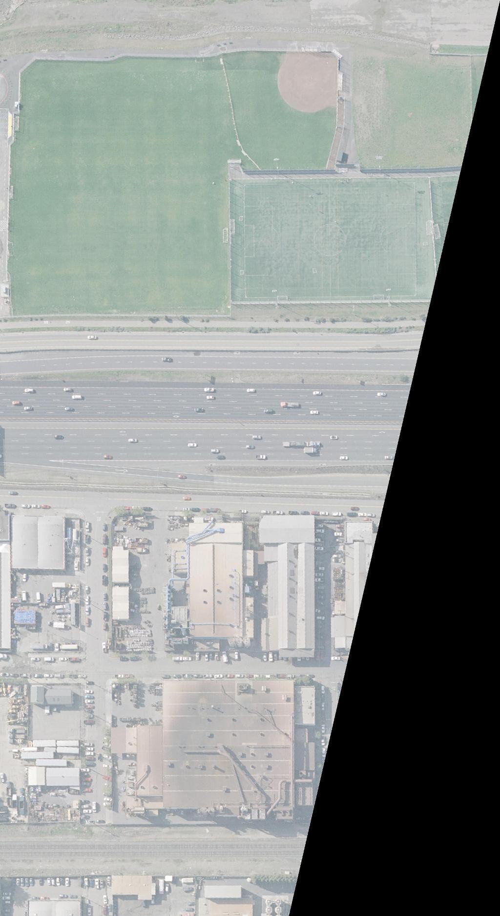

53 N PLAN
54 N PLAN PLAN PLAN PRELIMINARY - NOT FOR CONSTRUCTION
55
56
57
58
59 ATTACHMENT C Typical Cross Sections
60 SECTION A-A SECTION C-C SECTION B-B SECTION D-D PRELIMINARY - NOT FOR CONSTRUCTION
61 SECTION E-E SECTION F-F SECTION G-G PRELIMINARY - NOT FOR CONSTRUCTION
62 SECTION H-H PRELIMINARY - NOT FOR CONSTRUCTION
63 ATTACHMENT D Capital Outlay Project Estimate
64 PROJECT STUDY REPORT COST ESTIMATE SUMMARY District-County-Route 04-ALA-080 PM 6.5/6.7 EA 04-0A770K Program Code PROJECT DESCRIPTION: Limits On Interstate 80 at Gilman Street undercrossing between 0.7 miles east of University Avenue Overcrossing and 0.5 miles west of Buchannan Street Undercrossing. Proposed Improvement (Scope) Freeway Interchange Intersection Improvements. Reconfiguration of I-80 ramps and ramp intersections, and reconstruction of Gilman Street from north of West Frontage Road to south of 2nd St. Alternative Build Alternative 1 - Signalized Intersection SUMMARY OF PROJECT COST ESTIMATE TOTAL ROADWAY ITEMS $ 1,450,400 TOTAL STRUCTURES ITEMS $ 0 SUBTOTAL CONSTRUCTION COSTS $ 1,450,400 TOTAL RIGHT OF WAY ITEMS $ 0 TOTAL PROJECT CAPITAL OUTLAY COSTS $ 1,450,400 Reviewed by District Program Manager (Signature) Date Approved by Project Manager Phone No. (Signature) Date Revised
65 PROJECT STUDY REPORT COST ESTIMATE SUMMARY District-County-Route 04-ALA-080 PM 6.5/6.7 EA 04-0A770K I. ROADWAY ITEMS Section 1 Earthwork Quantity Unit Unit Price Item Cost Section Cost Roadway Excavation 210 CY $38 $7,880 Imported Borrow $0 Clearing & Grubbing 0.03 AC $3,743 $120 Develop Water Supply $0 Top Soil Reapplication $0 Stepped Slopes and Slope $0 Rounding (Contour Grading) $0 $0 Subtotal Earthwork $8,000 Section 2 Pavement Structural Section* Quantity Unit Unit Price Item Cost Section Cost PCC Pavement ( Depth) $0 PCC Pavement ( Depth) $0 Asphalt Concrete (bus pull-out area) 135 TONS $113 $15,260 Grind Existing Conc Pavement (to depth of 4") 7,240 SY $6 $44,600 Asphalt Concrete (to depth of 4") 1,630 TONS $113 $184,190 Lean Concrete Base $0 Cement-Treated Base $0 Aggregate Base 210 CY $85 $17,800 Treated Permeable Base $0 Aggregate Sub base $0 Pavement Reinforcing Fabric $0 Minor Concrete (Curb & Gutter) 15 CY $623 $9,350 Edge Drains $0 $0 Subtotal Pavement Structural Section $271,200 Section 3 Drainage Quantity Unit Unit Price Item Cost Section Cost Large Drainage Facilities $0 Storm Drains $0 Pumping Plants $0 Project Drainage $0 (X-Drains, overside, etc.) $0 Subtotal Drainage $0 * Reference sketch showing typical pavement structural section elements of the roadway. Include (if available) T.I., R-Value and date when tests were performed.
66 PROJECT STUDY REPORT COST ESTIMATE SUMMARY District-County-Route 04-ALA-080 PM 6.5/6.7 EA 04-0A770K Section 4 Specialty Items Quantity Unit Unit Price Item Cost Section Cost Retaining Walls $0 Noise Barriers $0 Barriers and Guardrails $0 Equpment/Animal Passes $0 Water Pollution Control $0 Hazardous Waste Investigation $0 and/or Mitigation Work Environmental Compliance $0 Resident Engineer Office Space $0 $0 Subtotal Specialty Items $0 Section 5 Traffic Items Quantity Unit Unit Price Item Cost Section Cost Lighting $0 Traffic Delineation Items $0 Traffic Signals $0 Signal and Lighting 1 LS $450,000 $450,000 Overhead Sign Structures $0 Roadside Signs $0 Paint Traffic Stripe (2-coat) 3,500 LF $1 $3,500 Paint Pavement Marking (2-coat) 370 SF $3 $1,110 Ramp Metering $0 Traffic Control Systems $0 Traffic Operations Systems 1 LS $112,000 $112,000 Temp Traffic Control 1 LS $50,000 $50,000 Transportation Management Plan $0 Temporary Detection System Staging 1 LS $40,000 $40,000 Subtotal Traffic Items $656,610
67 PROJECT STUDY REPORT COST ESTIMATE SUMMARY District-County-Route 04-ALA-080 PM 6.5/6.7 EA 04-0A770K Section 6 Planting and Irrigation Quantity Unit Unit Price Item Cost Section Cost Highway Planting $0 Replacement Planting $0 Irrigation Modification $0 Relocate Existing Irrigation $0 Facilities $0 Irrigation Crossovers $0 $0 Subtotal Planting and Irrigation Section $0 Section 7 Roadside Management and Quantity Unit Unit Price Item Cost Section Cost Safety Section Vegetation Control Treatments 1 LS $6,000 $6,000 Gore Area Pavement $0 Pavement beyond the gore area $0 Miscellaneous Paving $0 Erosion Control Slope Protection $0 Side Slopes/Embankment Slopes $0 Maintenance Vehicle Pull outs $0 Off-freeway Access (gates, stairways, etc.) $0 Roadwide Facilities (Vista Points, Transit Park and Ride, etc.) $0 Relocating roadside facilities/features $0 $0 Subtotal Traffic Items $6,000 TOTAL SECTIONS 1 thru 7 $941,810
68
69
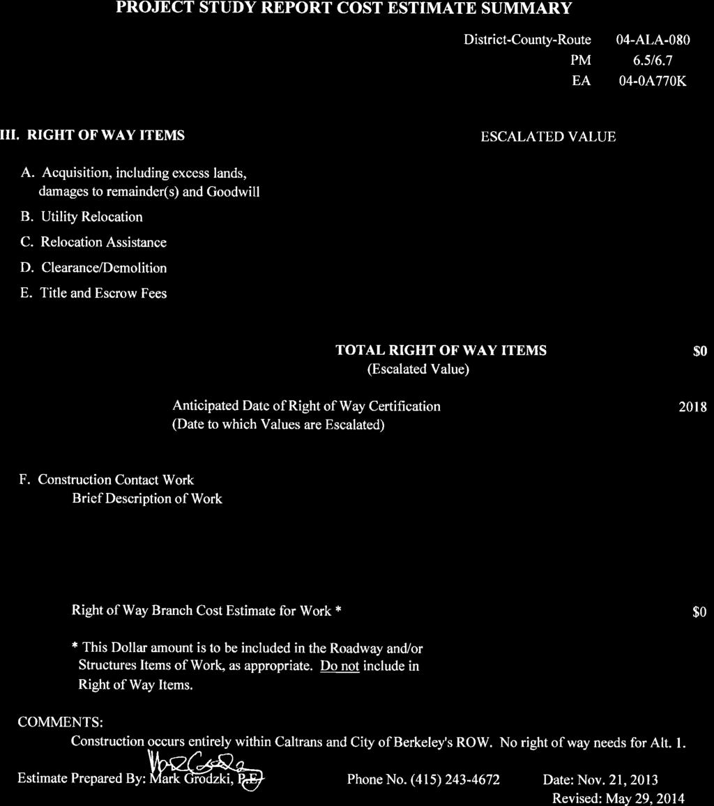
70
71 THIS PAGE INTENTIONALLY LEFT BLANK.
72 PROJECT STUDY REPORT COST ESTIMATE SUMMARY District-County-Route 04-ALA-080 PM 6.5/6.7 EA 04-0A770K Program Code PROJECT DESCRIPTION: Limits On Interstate 80 at Gilman Street undercrossing between 0.7 miles east of University Avenue Overcrossing and 0.5 miles west of Buchannan Street Undercrossing. Proposed Improvement (Scope) Freeway Interchange Intersection Improvements. Reconfiguration of I-80 ramps and ramp intersections, and reconstruction of Gilman Street from north of West Frontage Road to south of 2nd St. Alternative Build Alternative 2 - Roundabout Intersection SUMMARY OF PROJECT COST ESTIMATE TOTAL ROADWAY ITEMS $ 8,003,600 TOTAL STRUCTURES ITEMS $ 0 SUBTOTAL CONSTRUCTION COSTS $ 8,003,600 TOTAL RIGHT OF WAY ITEMS $ 1,180,000 TOTAL PROJECT CAPITAL OUTLAY COSTS $ 9,183,600 Reviewed by District Program Manager (Signature) Date Approved by Project Manager Phone No. (Signature) Date Revised
73 PROJECT STUDY REPORT COST ESTIMATE SUMMARY District-County-Route 04-ALA-080 PM 6.5/6.7 EA 04-0A770K I. ROADWAY ITEMS Section 1 Earthwork Quantity Unit Unit Price Item Cost Section Cost Roadway Excavation 23,500 CY $38 $893,000 Imported Borrow $0 Clearing & Grubbing 1.60 AC $3,743 $5,990 Develop Water Supply 1 LS $15,000 $15,000 Top Soil Reapplication $0 Stepped Slopes and Slope $0 Rounding (Contour Grading) $0 $0 Subtotal Earthwork $913,990 Section 2 Pavement Structural Section* Quantity Unit Unit Price Item Cost Section Cost PCC Pavement ( Depth) $0 PCC Pavement ( Depth) $0 Asphalt Concrete + 16,153 TONS $113 $1,825,320 Lean Concrete Base $0 Cement-Treated Base $0 Aggregate Base 330 CY $85 $27,970 Treated Permeable Base $0 Aggregate Sub base $0 Pavement Reinforcing Fabric $0 Minor Concrete (Curb & Gutter) 370 CY $623 $230,510 Edge Drains $0 $0 Subtotal Pavement Structural Section $2,083,800 Section 3 Drainage Quantity Unit Unit Price Item Cost Section Cost Large Drainage Facilities $0 Storm Drains $0 Modify Inlet 7 EA $2,401 $16,810 Adjust Manhole 8 EA $1,413 $11,300 Catch Basins Pumping Plants $0 Project Drainage $0 (X-Drains, overside, etc.) $0 Subtotal Drainage $28,110 * Assume TI=14 and R=5 with design life of 30 years + Assumes Roadway Pavement section is full depth (23") Hot Mix Asphalt with no AB
74 PROJECT STUDY REPORT COST ESTIMATE SUMMARY District-County-Route 04-ALA-080 PM 6.5/6.7 EA 04-0A770K Section 4 Specialty Items Quantity Unit Unit Price Item Cost Section Cost Retaining Walls $0 Noise Barriers $0 Barriers and Guardrails $0 Architectural Treatment 7,750 SF $12 $93,000 Concrete Barrier (Type 60) 740 LF $106 $78,440 Equpment/Animal Passes $0 Water Pollution Control Plan 1 LS $7,500 $7,500 Water Pollution Control Implementation 1 LS $75,000 $75,000 Hazardous Waste Investigation 1 LS $13,000 $13,000 and/or Mitigation Work Environmental Compliance $0 Permanent Treatment BMPs 1 LS $250,000 $250,000 Resident Engineer Office Space 1 LS $280,000 $280,000 $0 Subtotal Specialty Items $796,940 Section 5 Traffic Items Quantity Unit Unit Price Item Cost Section Cost Lighting 1 LS $100,000 $100,000 Traffic Delineation Items $0 Thermoplastic Traffic Stripe (various widths) 9,160 LF $0.75 $6,870 Paint Pavement Marking (2-coat) 730 SF $3.82 $2,790 Traffic Signals $0 Overhead Sign Structures 1 LS $125,000 $125,000 Roadside Signs 56 EA $550 $30,800 Ramp Metering 1 LS $60,000 $60,000 Traffic Control Systems $0 Traffic Operations Systems 1 LS $112,000 $112,000 Transportation Management Plan 1 LS $12,100 $12,100 Temporary Detection System Staging 1 LS $40,000 $40,000 Temp Traffic Control/Traffic Handling- Staging 1 LS $250,000 $250,000 Subtotal Traffic Items $739,560
75 PROJECT STUDY REPORT COST ESTIMATE SUMMARY District-County-Route 04-ALA-080 PM 6.5/6.7 EA 04-0A770K Section 6 Planting and Irrigation Quantity Unit Unit Price Item Cost Section Cost Highway Planting 1 LS $103,000 Replacement Planting $0 Irrigation Modification 1 LS $7,500 $7,500 Relocate Existing Irrigation $0 Facilities $0 Water Meters 2 EA $10,000 $20,000 Irrigation Crossovers 2,000 LF $3 $6,500 Plant Establishment 1 LS $8,000 $8,000 Subtotal Planting and Irrigation Section $145,000 Section 7 Roadside Management and Quantity Unit Unit Price Item Cost Section Cost Safety Section Vegetation Control Treatments 4,520 SY $62 $280,920 Gore Area Pavement $0 Pavement beyond the gore area $0 Concrete Pavers 12,590 SF $15 $188,850 Miscellaneous Paving $0 Erosion Control Slope Protection $0 Side Slopes/Embankment Slopes 210 CY $95 $19,950 Maintenance Vehicle Pull outs $0 Off-freeway Access (gates, stairways, etc.) $0 Roadwide Facilities (Vista Points, Transit Park and Ride, etc.) $0 Relocating roadside facilities/features $0 $0 Subtotal Traffic Items $489,720 TOTAL SECTIONS 1 thru 7 $5,197,120

76
77
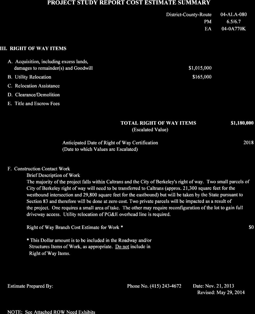

78
79 THIS PAGE INTENTIONALLY LEFT BLANK.
80 PROJECT STUDY REPORT COST ESTIMATE SUMMARY District-County-Route 04-ALA-080 PM 6.5/6.7 EA 04-0A770K Program Code PROJECT DESCRIPTION: Limits On Interstate 80 at Gilman Street undercrossing between 0.7 miles east of University Avenue Overcrossing and 0.5 miles west of Buchannan Street Undercrossing. Proposed Improvement (Scope) Freeway Interchange Intersection Improvements. Reconfiguration of I-80 ramps and ramp intersections, and reconstruction of Gilman Street from north of West Frontage Road to south of 2nd St. Alternative Build Alternative 3 - Roundabout Intersection with Bypass Ramps SUMMARY OF PROJECT COST ESTIMATE TOTAL ROADWAY ITEMS $ 8,896,200 TOTAL STRUCTURES ITEMS $ 0 SUBTOTAL CONSTRUCTION COSTS $ 8,896,200 TOTAL RIGHT OF WAY ITEMS $ 1,180,000 TOTAL PROJECT CAPITAL OUTLAY COSTS $ 10,076,200 Reviewed by District Program Manager (Signature) Date Approved by Project Manager Phone No. (Signature) Date Revised
81 PROJECT STUDY REPORT COST ESTIMATE SUMMARY District-County-Route 04-ALA-080 PM 6.5/6.7 EA 04-0A770K I. ROADWAY ITEMS Section 1 Earthwork Quantity Unit Unit Price Item Cost Section Cost Roadway Excavation 30,230 CY $38 $1,148,740 Imported Borrow $0 Clearing & Grubbing 2.37 AC $3,743 $8,870 Develop Water Supply 1 LS $15,000 $15,000 Top Soil Reapplication $0 Stepped Slopes and Slope $0 Rounding (Contour Grading) $0 $0 Subtotal Earthwork $1,172,610 Section 2 Pavement Structural Section* Quantity Unit Unit Price Item Cost Section Cost PCC Pavement ( Depth) $0 PCC Pavement ( Depth) $0 Jointed Plain Concrete Pavement ~ 630 CY $356 $224,440 Lean Concrete Base 370 CY $263 $97,130 Asphalt Concrete + 15,282 TONS $113 $1,726,860 Lean Concrete Base $0 Cement-Treated Base $0 Aggregate Base 240 CY $85 $20,340 Treated Permeable Base $0 Aggregate Sub base $0 Pavement Reinforcing Fabric $0 Minor Concrete (Curb & Gutter) 440 CY $623 $274,120 Edge Drains $0 $0 Subtotal Pavement Structural Section $2,342,890 Section 3 Drainage Quantity Unit Unit Price Item Cost Section Cost Large Drainage Facilities $0 Storm Drains $0 18" RCP 400 LF $250 $100,000 Modify Inlet 7 EA $2,401 $16,810 Adjust Manhole 8 EA $1,413 $11,300 Catch Basins 8 EA $2,100 $16,800 Pumping Plants $0 Project Drainage $0 (X-Drains, overside, etc.) $0 Subtotal Drainage $144,910 * Assume TI=14 and R=5 with design life of 30 years. + Assumes Roadway Pavement section is full depth (23") Hot Mix Asphalt with no AB ~ Roadway pavement underneath the I-80 structure to be 0.85 ft JPCP / 0.50 ft LCB / 0.75 ft AS
82 PROJECT STUDY REPORT COST ESTIMATE SUMMARY District-County-Route 04-ALA-080 PM 6.5/6.7 EA 04-0A770K Section 4 Specialty Items Quantity Unit Unit Price Item Cost Section Cost Retaining Walls $0 Noise Barriers $0 Barriers and Guardrails $0 Architectural Treatment 7,750 SF $12 $93,000 Concrete Barrier (Type 60) 810 LF $106 $85,810 Equpment/Animal Passes $0 Water Pollution Control Plan 1 LS $7,500 $7,500 Water Pollution Control Implementation 1 LS $75,000 $75,000 Hazardous Waste Investigation 1 LS $13,000 $13,000 and/or Mitigation Work Environmental Compliance $0 Permanent Treatment BMPs 1 LS $250,000 $250,000 Resident Engineer Office Space 1 LS $280,000 $280,000 $0 Subtotal Specialty Items $804,310 Section 5 Traffic Items Quantity Unit Unit Price Item Cost Section Cost Lighting 1 LS $100,000 $100,000 Traffic Delineation Items $0 Thermoplastic Traffic Stripe (various widths) 10,810 LF $0.75 $8,110 Paint Pavement Marking (2-coat) 440 SF $3.82 $1,680 Traffic Signals $0 Overhead Sign Structures 1 LS $125,000 $125,000 Roadside Signs 58 EA $550 $31,900 Ramp Metering 1 LS $60,000 $60,000 Traffic Control Systems $0 Traffic Operations Systems 1 LS $112,000 $112,000 Transportation Management Plan 1 LS $12,100 $12,100 Temporary Detection System Staging 1 LS $40,000 $40,000 Temp Traffic Control/Traffic Handling- Staging 1 LS $250,000 $250,000 Subtotal Traffic Items $740,790
83 PROJECT STUDY REPORT COST ESTIMATE SUMMARY District-County-Route 04-ALA-080 PM 6.5/6.7 EA 04-0A770K Section 6 Planting and Irrigation Quantity Unit Unit Price Item Cost Section Cost Highway Planting 1 LS $91,000 $91,000 Replacement Planting $0 Irrigation Modification 1 LS $25,000 $25,000 Relocate Existing Irrigation $0 Facilities $0 Water Meters 2 EA $10,000 $20,000 Irrigation Crossovers 2,000 LF $3 $6,000 Plant Establishment 1 LS $8,000 $8,000 Subtotal Planting and Irrigation Section $150,000 Section 7 Roadside Management and Quantity Unit Unit Price Item Cost Section Cost Safety Section Vegetation Control Treatments 3,290 SY $62 $204,470 Gore Area Pavement $0 Pavement beyond the gore area $0 Miscellaneous Paving $0 Concrete Pavers 12,550 SF $15 $188,250 Erosion Control Slope Protection $0 Side Slopes/Embankment Slopes 300 CY $95 $28,500 Maintenance Vehicle Pull outs $0 Off-freeway Access (gates, stairways, etc.) $0 Roadwide Facilities (Vista Points, Transit Park and Ride, etc.) $0 Relocating roadside facilities/features $0 $0 Subtotal Traffic Items $421,220 TOTAL SECTIONS 1 thru 7 $5,776,730
84
85
86
87 THIS PAGE INTENTIONALLY LEFT BLANK.
88 ATTACHMENT E Preliminary Environmental Analysis Report (PEAR) Under Separate Cover
89 ATTACHMENT F Right-of-way Conceptual Cost Estimate Component
90 CONCEPTUAL COST ESTIMATE REQUEST RIGHT OF WAY COMPONENT To: Julie McDaniel Date 05/30/2014 Senior Right-of-Way Agent, District 4 From: Dist-Co-Rte-PM 04 ALA /6.7 Project ID EA 04 0A770K Project Description I-80 Gilman Street Interchange The above-referenced project will require a(n) Original/Updated Conceptual Cost Estimate for the Right of Way Component by (date). Project Information Type and description of the project. Project Setting: Urban Rural Current Land Use: Commercial and Industrial Project Schedule: PID Date PA&ED Date RWC Date Number of Alternatives to be Studied 4 (incl. No Build) Environmental Document Type_IS/EA and MND/FONSI Environment Mitigation Parcels/Credits Anticipated: Yes No Unknown Environmental Permits: Number Permits Needed Prior to PA&ED Nil Permits to Enter for Environmental/Engineering Studies Nil Number of Public Meetings Anticipated TBD. Controversial: Yes No Unknown Right of Way Requirements Additional R/W: Number of Parcels 3 Total Additional Area 62,000 to 65,000 square feet Number of Easements 1 Total Easement Area TBD Access Points/Control: No Anticipated Change Change is Anticipated Identify Change in Access: New access control is located at entrance of roundabouts (see attached Right-of-way Need exhibits) Utilities: None Minor Major Types of Utility facilities: PG&E Overhead Electrical Line Relocation Potholing Needed Number Railroad: Identify Rail Companies in the Vicinity of the Project: Amtrak, Union Pacific Railroad and Burlington Northern Santa Fe List Possible RR Needs (e.g. Flagging ): Flagging and temporary traffic control No Rail Companies in the Vicinity of the Project Existing Facilities: No Relinquishments/Vacations Relinquishments Vacations Proposed Facilities: No Relinquishments Relinquishments 1
91 CONCEPTUAL COST ESTIMATE RIGHT OF WAY COMPONENT To: Julie McDaniel Date 07/10/2014 Senior Right-of-Way Agent, District 4 From: Dist-Co-Rte-PM 04 ALA /6.7 Project ID EA 04 0A770K Project Description I-80 Gilman Street Interchange A Field Review was conducted _X Yes No ( on 11/01/2013) Scope of the Right of Way Provide a general description of the right of way including the location attributes. Right of Way Required _X Yes No Number of Parcels X >100 X_Urban Rural Land Area: Fee Easement TBD Displaced Persons/Businesses Yes _X No Demolition/Clearance Yes X_No Railroad Involvement X Yes No Utility Involvements X Yes No 10_Number of Utilities in area Cost Estimates Support Costs $0-$25,000 $500,001-$1,000,000 $25,001-$100,000 $1,000,001-$5,000,000 X $100,001-$250,000 $5,000,001-$10,000,000 $250,001-$500,000 >$10,000,000 Capital Costs $0-$100,000 $5,000,001-$15,000,000 $100,001-$500,000 $15,000,001-$50,000,000 $500,001-$1,000,000 $50,000,001-$100,000,000 X $1,000,001-$5,000,000 >$100,000,000 Schedule Right of Way will require months to deliver a Right of Way Certification #1 from Final R/W Maps. This estimate is based on a Right of Way Certification date of TBD. 1
92 Areas of Concern Amtrak, Union Pacific Railroad and Burlington Northern Santa Fe serve freight and passenger trains along the Capitol Corridor that runs across Gilman Street at the 3 rd Street intersection, approximately 320 feet from the project site. Impact to any railroad s operating facility will result in complex right-of-way issues. Assumptions and Limiting Conditions Since the proposed roundabout would combine the frontage road intersections currently owned by the City of Berkeley with Caltrans ramp intersections, additional right-of-way will be required from the City of Berkeley for the construction of two roundabout alternatives. The proposed project will be built primary on existing State and City right-of-way designated for roadway. The improvements will require reconstruction of the entrance/exit to the Golden Gate Fields located on Gilman Street north of the West Frontage Road for which a small area of private right-of- way and a temporary construction easement (TCE) will be required. Pacific Steel Casting Company operates their facility located at the southwest quadrant of Gilman Street/ Eastshore Highway intersection. Their facility covers two parcels that are currently served by one single driveway entrance/exit in their westerly lot. The proposed roundabout alternatives will maintain the same single entrance/exit but the access control to be established over the roundabout will limit the future access on their easterly lot. There is no right-of-way take required from the two parcels. Further right-of-way assessment is anticipated during the PA/ED phase to evaluate the options for reconfiguring the two lots to allow full property access. The inclusion of roundabout in Caltrans right-of-way would establish future control over the point of entrance and exits to ensure the safe and efficient roadway operation. The latest Caltrans Highway Design Manual Index (14) and provide guidelines on the limits of access control over roundabout intersections. For new construction, access control of 100 feet beyond the inscribed circle diameter is recommended. As a minimum, access control shall extend at least 50 feet beyond the inscribed circle diameter. 2
93
94
95
96
97 ATTACHMENT G Risk Register
98 LEVEL 1 - RISK REGISTER Project Name: I-80 Gilman Street Interchange Project DIST- EA 04-0A770K Risk Identification Status ID # Type Category Title Risk Statement Current status/assumptions Priority Rating Risk Rating Project Manager Brady Nadell, Parsons Brinckerhoff Risk Response Rationale for Rating Strategy Response Actions Risk Owner Updated Active 100 Threat Environmental Project Data Due to insufficient project data and mapping available at the beginning of the environmental study, there are areas that need to be verified or Requested and obtained available required further study which may lead to data from various sources. various levels of environmental documents and mitigations to be indentified in subsequent stage Medium Project is in preliminary phase. There are limited amount of project data available. Additional investigation need to take place. If resources are identified as a result of XPI testing, Phase II evaluation will be required, resulting in increased project costs and additional schedule delay (up to 4 months). If cultural resources are determined eligible, a Finding of Effect (FOE) will be required. If impacts are adverse a Memorandum of Agreement (MOA) and Historic Property Treatment Plan (HPTP) would address mitigation requirements. If FHWA/SHPO disagrees with cultural resources effects finding and require extended MOA consultation, then increased project costs and additional schedule delay (up to 6 months) would occur. Mitigate Verify that data collected is accurate and complete. Obtain additional data and detailed mapping during environmental process (PAED) PB 12/26/2013 Active 101 Opportunity Environmental Design Change Design changes trigger additional environmental study that may increase the project costs and time. Preliminary design completed for PSR-PDS phase was based on previous traffic data. Detailed traffic analysis with most current data will be conducted in the next phase which may trigger design changes. Medium Design plans change to include activities not currently identified would increase project costs and schedule delay for cultural resources, traffic, air quality, etc. (1 additional year). Mitigate Monitor design changes against the footprint of environment study PB 12/26/2013 Active 102 Threat Environmental Floodplain Active 103 Threat Organizational Pedestrian and Bicycle Improvements Project area west of I-80 is located in Coastal Flood Zone (Zone VE). Additional time and resources are needed to address specific requirements for PAED and permitting. As a result of high expectation from the stakeholders and/or public on pedestrian and bicycle improvements, extensive public input is anticipated during the public outreach period that will may trigger additional design review/change. Construction outside of raining season Pedestrian and bicycle overpass may be studied and constructed as a separate project Medium Medium Encroachment in the floodplain will trigger a Location Hydraulic Study, Summary of Floodplain Encroachment Report and/or a Floodplain Evaluation Report. There is no formal outreach performed as of today. Accept Accept Schedule contract work to avoid raining season. Coordinate with BCDC during the next phase to determine required permits and additional mitigation measures, if any. Address concerns of stakeholders and public during environmental process ACTC 12/26/2013 ACTC 12/26/2013 Level 1 Risk Register
99 LEVEL 1 - RISK REGISTER Project Name: I-80 Gilman Street Interchange Project DIST- EA 04-0A770K Risk Identification Status ID # Type Category Title Risk Statement Current status/assumptions Active 104 Threat Organizational Review Time Active 105 Threat Organizational Permitting Active 106 Threat Design Groundwater Active 107 Threat Design Subsurface Soil Active 108 Threat Design Design Exception Active 109 Threat Design Existing Subsurface Structures As a result of multiple agency participation, reviewing agency may require longer than expected review time resulting in schedule delay. As a result of water quality regulations change, there may be new storm water requirements that need to to be addressed. Failure to address these requirements will result in storm water permit delay. Due to the presence of high water table at the site, construction will subject to groundwater effect which will require additional mitigation measures during construction. Due to the presence of very soft organic clay (bay mud) materials, it may require over-excavation to replace the weak soil materials which will increase the cost and time for construction. Delay in Design Exception review and approval may affect the project schedule which will result in overall project delay. Due to the shallow footing of bridge columns and abutment walls, construction may be in conflict with the existing substructures which will require mitigation. Priority Rating Medium Risk Rating Project Manager Brady Nadell, Parsons Brinckerhoff Risk Response Rationale for Rating Strategy Response Actions Risk Owner Updated Extensive review time by multiple parties may cause an cumulative effect on schedule. Avoid Ensure review period follows project schedule ACTC 12/26/2013 Low Accept Identify permit requirements early on PB 12/26/2013 High High Low High Based on available as-built log of test borings information, groundwater is encountered at 7 to 8 feet below ground. In review of the log of test borings, the top 10 feet of surface soil materials are identified as very loose to loose sand and very soft organic clay (bay mud). The project proposes to remove the existing and construct new pavement which will subject to subsurface soil effect. Caltrans headquarter geometrians have been involved in the project development and geometric review process. Due to the presence of weak subgrade soils and high volume of truck traffic, a thicker pavement section will be required. The construction of the new pavement section may be in conflict with the existing shallow subsurface structures. Mitigate Mitigate Avoid Mitigate Verify the required depth of excavation. Employ dewatering activities during construction. Implement necessary soil stability device when determined needed. Proof-rolling of the pavement excavated subgrade with at least 25-ton roller or equivalent equipment is required to identify weak or soft areas. If such anomalies are evident, over-excavate the soft areas to expose competent soils and replace them with structural fill soils and compact to 95% relative compaction. Engage geometric reviewer in PDT meetings Verify design with existing subsurface structures for conflict PB 12/26/2013 PB 12/26/2013 Caltrans 12/26/2013 PB 12/26/2013 Due to the presence of hazardous materials and contaminated soil in the Active 110 Threat Environmental Hazardous Materials site, it may require additional mitigation measures increasing project costs and time. Active 111 Threat Design Railroad Requirements Due to the close proximity of active railroad tracks adjacent to the project site, temporary traffic handling and construction staging need to take into the consideration of special railroad requirements in which additional time for railroad coordination is required. Medium Medium If unforeseen issues of hazardous waste, air quality, noise or traffic impacts are encountered, then increased project costs, schedule delay (6 months or longer) would occur. Any unforeseen restrictions required by the railroad agencies would affect the construction staging scheme and the timing of construction. Mitigate Identify site with hazardous materials PB 12/26/2013 Mitigate Consider railroad needs when developing construction staging plans PB 12/26/2013 Level 1 Risk Register
100 LEVEL 1 - RISK REGISTER Project Name: I-80 Gilman Street Interchange Project DIST- EA 04-0A770K Risk Identification Status ID # Type Category Title Risk Statement Current status/assumptions Active 112 Threat Design Roadway Access Active 113 Threat ROW Utility Relocation Active 114 Threat ROW Railroad Involvement Active 115 Threat ROW City Land Transfer Active 116 Threat Construction Utility Active 117 Threat Construction Sea water level Active 118 Threat Construction Roadway closures Active 119 Threat PM Programming Active 120 Threat Organizational Funding Due to the construction of the roundabouts, permanent change of roadway geometries and access to adjacent properties is anticipated which may affect local business. Existing overhead utilities will be in conflict with construction. If utility relocation requires more time than planned, it will affect construction schedule. There is a planned grade separation project along the 3rd Street railroad corridor immediately adjacent to the project site. Any unforeseen railroad involvement may trigger additional review time and/or changes. The roundabout alternatives require additional right-of-way from the City of Berkeley. If city land transfer process takes longer than anticipated, it may affect the project schedule. Unidentified utilities that may lead to incorrect assumptions affecting the construction costs and schedule. Due to raise in sea water level and the close proximity of the project site to the coast line, there is a potential change in underground water table in which dewatering and other mitigation activities are required during construction. The project will cause temporary street and ramp closures during stage construction. If the subject closures are not well coordinated with local community and business owners, distribution of accurate and timely information to the public may be jeopardized resulting in traffic delay. Delay in earlier project phases jeopardizes ability to meet programmed delivery commitment Funding changes during project development (PID) may affect the delivery of subsequent phases. Priority Rating Medium Medium Low Low Low Medium Medium Low Risk Rating Project Manager Brady Nadell, Parsons Brinckerhoff Risk Response Rationale for Rating Strategy Response Actions Risk Owner Updated There is no formal community outreach performed to educate the local business about the project. It is assumed that the railroad grade separation project will take place after the completion of this project. Therefore, minimum conflict is anticipated. It is anticipated that right-ofway assessment will take place during the PAED phase to avoid delay. Project is in preliminary phase. There are limited amount of project data available. Additional investigation need to take place to verify data. Based on Guidance on Sea Level Rise, for project located adjacent to California coast line with design life of 20 years or more, a Sea Level Rise (SLR) analysis is required to address the high likelihood of being impacted by SLR. Mitigate Mitigate Avoid Avoid Avoid Accept Avoid Avoid Discuss with local community and business on the permanent impact and allow input during environmental phase. Begin utility coordination with utility owners early on Coordinate closely with the City on the timing of railroad project Request right-of-way assessment early on. Address right-of-way need in co-op agreement Request additional utility information during PAED Closely monitor water-level due to close proximity to the shore A Traffic Management Plan will be developed during the PAED phase to identify preliminary traffic impacts and mitigation, and to inform local community and business about the temporary changes to roadway access and road/ramp closures. Community outreach to impacted parties should also be peformed. Periodic update of project schedule to reflect changes City of Berkeley 12/26/2013 ACTC 12/26/2013 City of Berkeley 12/26/2013 City of Berkeley 12/26/2013 PB 12/26/2013 City of Berkeley 12/26/2013 City of Berkeley 12/26/2013 ACTC 12/26/2013 High Accept ACTC 12/26/2013 Level 1 Risk Register
101 LEVEL 1 - RISK REGISTER Project Name: I-80 Gilman Street Interchange Project DIST- EA 04-0A770K Risk Identification Status ID # Type Category Title Risk Statement Current status/assumptions Active 121 Threat Organizational Funding Active 122 Threat Organizational Permits and Agreement Active 123 Threat Environmental Public Outreach Active 124 Threat Environmental Native American Active 125 Threat ROW Driveway in Conflict with Access Control Active 126 Threat ROW Private property ROW Take Capital funding is not available for rightof-way or construction. If the capital outlay funds are not readily available after the completion of PAED, construction may be delayed. Permitting and co-op agreement processes are in preliminary stage. Schedule delay due to permits or co-op agreement delay from State or local agencies will delay the delivery of the project. Due to public interest in the project, additional time for public involvement and outreach may be needed, which would delay the project schedule (up to 3 months). If unexpected Native American concerns arises, significant controversy would increase costs and delay schedule Existing driveways will be in conflict with future access control for roundabout intersections and their operation. The roundabout alternatives require additional right-of-way from Golden Gate Field. Other right-of-way takes may be determined necessary as details are developed in the next phase. If right-of-way acqusition takes longer than anticipated, it may affect the project schedule. Priority Rating High Medium Medium Risk Rating Project Manager Brady Nadell, Parsons Brinckerhoff Risk Response Rationale for Rating Strategy Response Actions Risk Owner Updated There is no formal outreach performed as of today. Accept Avoid Mitigate Include the project in expenditure plan for the next tax measure Identify required permits and agreement. Draft co-op agreement for PAED and PS&E prior to the next phase Conduct early outreach and continuous outreach with potentially affected community members and stakeholders ACTC 12/26/2013 ACTC 12/26/2013 PB 12/26/2013 Low Mitigate PB 12/26/2013 High Medium Current design indicates that the existing driveways will be located within 100' of the roundabount intersections (measured from the inscribed circle diameter) in which design exception for access control is required. It is anticipated that right-ofway assessment will take place during the PAED phase to avoid delay. Mitigate Mitigate Discuss with local community and business on the permanent impact and allow input during environmental phase. Identify any permanent driveway impact and access relocation early on. Request right-of-way assessment early on. Discuss with property owner of the subject right-of-way take and allow input during environmental phase. City of Berkeley 3/31/2014 City of Berkeley 3/31/2014 Level 1 Risk Register
102 ATTACHMENT H Storm Water Document Storm Water Data Report - Under Separate Cover
103 ATTACHMENT I Traffic Engineering Performance Assessment
104 7/09/2014 Alameda County Transportation Commission (Alameda CTC) City of Berkeley Interstate 80 at Gilman Street Interchange Traffic Engineering Performance Assessment By Parsons Brinckerhoff Project Proposal Identification District County Route Limits: 04 ALA /6.7 On Gilman Street from West Frontage Road to 2 nd Street 1. Facility Type: Urban Interchange 2. Project Type: New Facility 3. Targeted System User: Motor Vehicles, Bicyclists & Pedestrians 4. Key Transportation Agencies: City of Berkeley, Caltrans 5. Context: Urban 6. Project Manager: Brady Nadell, Project Manager, Parsons Brinckerhoff (PB); Raj Murthy, Program/Project Manager, Alameda CTC Background This traffic engineering performance assessment (TEPA) documents the results of existing and future year traffic conditions analysis at I 80 and Gilman Street Interchange. The evaluation of this assessment was based on existing and future traffic volume conditions being served by signalized intersections or roundabouts. Gilman Street is a four lane arterial roadway within City of Berkley, California. It carries four lanes (two lanes in each direction) within the study area and reduces to two lanes south of 2 nd Street (with one lane in each direction). Figure 1 shows the existing roadway network. I 80 eastbound and westbound on and off ramps intersect with Gilman Street. There is an existing West Frontage Road intersection located on Gilman Street just north of the westbound off ramp. Eastshore Highway crosses Gilman Street to the south of the I 80 eastbound ramp intersection. Stop control are provided on these four intersections on side streets only. Due to the closely spaced intersections and lack of proper traffic control devices, the interchange experiences complex traffic turning movements. The goal of the project is to develop an alternative that will address the existing and future traffic operational deficiencies. The TEPA study consists of a detailed traffic operations analysis of the four major arterial intersections within the project study area. A total of four alternatives are studied under the TEPA: Page 1
105 No Build Build Alternative 1: Signalized Intersection Build Alternative 2: Roundabout Intersection Build Alternative 3: Roundabout Intersection with Bypass Ramps Page 2

106 Figure 1: I 80 and Gilman Street Interchange Study Area Page 3
107 Summary of Preliminary Findings & Recommendations Assessment Approach, Data Sources & Assumptions The evaluation of existing and future traffic conditions for these four intersections includes traffic signal operation and roundabout operation analyses. These analyses utilize the methodologies provided in the Highway Capacity Manual (HCM) to determine a Level of Service (LOS) for each intersection. A LOS is an alphabetical grade (A through F) that summarizes how well the facility can accommodate users under a set of operational conditions. Typically, an LOS of D or better is considered acceptable. A brief summary of the analysis methodologies is provided in a following section. Forecasted Traffic Volumes & Conditions The future traffic volumes for the signalized intersection analysis were developed using 2011 existing traffic counts and applying a growth factor to obtain 2030 and 2040 design year traffic forecast. The growth rates from 2011 existing year to 2030 were based on the West Berkeley Master Plan (WBMP) 2007 to 2030 growth rates growth rates were derived by linear extrapolation of year 2007 to 2030 growth rates. Table 1 shows the existing and future traffic volumes for AM and PM peak periods, respectively. Page 4
108 Table 1: Existing and Future Intersection Traffic Volumes (vehicles per hour) West I 80 Ramp Terminal (L=left, R=right, and T=through) AM WB West Frontage NB Gilman St WB Off Ramp SB Gilman St L R T R R L T L T T L T R L R T T T T R R PM WB West Frontage NB Gilman St WB Off Ramp SB Gilman St L R T R R L T L T T L T R L R T T T T R R East I 80 Ramp Terminal AM EB Off Ramp EB Eastshore Hwy NB Gilman St SB Eastshore Hwy NB Gilman St L T R L R T R R L T L R T R L T T T R R L T R T R R L T L T T T R e PM EB Off Ramp EB Eastshore Hwy NB Gilman St SB Eastshore Hwy EB Gilman St L T R L R T R R L T L R T R L T T T R R L T R T R R L T L T T T R Page 5
109 Modeling Tools / Methodologies Traffic Signal Methodologies Intersection capacity and LOS were determined using the SYNCHRO (Version 8) signalized intersection analysis software program based on the theory and methodologies contained in the HCM (Table 2). For the purposes of this study, a deficiency is defined as LOS E or worse. Table 2: Level Of Service Criteria for Signalized Intersections Level of Service Control Delay per Vehicle A <10 B > C > D > E > F > 80 Source: 2010 Highway Capacity Manual Roundabout Methodologies All roundabout analysis was conducted using the 2010 (HCM) methodology within SIDRA roundabout analysis software program. Delay and LOS performance measures were developed within SIDRA and compared to the threshold of LOS E. A target volume to capacity (v/c) ratio of 0.85 to 0.90 was used as an upper threshold for design, as suggested by NCHRP Report 672, Roundabouts: An Informational Guide. Queue storage was also compared against available storage lengths, particularly between the roundabouts and on the I 80 off ramps. California specific critical headway and follow up headway acceptance parameters documented in Caltrans Research Project #65A0229, Roundabout Geometric Design Guidance, were used within SIDRA to predict capacity for each approach. These parameters calibrate the 2010 HCM methodology to more closely reflect California drivers behaviors. Traffic Analysis Traffic Signal Operational Analysis (Build Alternative 1) The traffic signal operations for existing and future conditions were evaluated for the eastbound and westbound ramp terminal intersections. Figure 2 shows the traffic signal phasing at the intersection. Each ramp terminal and adjacent frontage road was analyzed as a single signalized intersection due to the physical proximity of frontage roads to the existing ramp terminals. As shown in the phasing diagram, each individual approach has to be split phased to accommodate all the movements and to allow for safe operation of the turning movements. Page 6
 for the existing condition (year 2011).")
110 Figure 2: I 80 and Gilman Street Interchange Signal Phasing Tables 3 and 4 summarize the traffic signal operations level of service for the study years. As shown in Tables 3 and 4, the study intersections operate at a reduced LOS during the PM peak hour (LOS E) for the existing condition (year 2011). Due to the projected traffic growth in year 2030 and 2040, the signalized intersections will experience further delays and operate between LOS D to LOS F. The primary cause of delay on the west ramp terminal intersection is due to the large volumes of traffic movements from the westbound off ramp turning into West Frontage Road, and from eastbound traffic on West Frontage Road to Gilman Street. At the east ramp terminal intersection, the reduced traffic operation is due to the extensive signal time for the five leg approaches with each movement required to operate as an individual split phase. Page 7
111 Table 3: Signalized Intersection Operational Analysis Results at West I 80 Ramp Terminal AM Peak Hour PM Peak Hour Approach Level of Service Volume to Capacity Ratio* Delay* (sec) 95 th Percentile Queue (feet) Level of Service Volume to Capacity Ratio* Delay* (sec) 95 th Percentile Queue (feet) 2011 Existing Conditions Build Alternative 1 Southbound Gilman St C C I 80 Westbound Offramp * Delay in seconds D F Northbound Gilman St C E I 80 West Frontage Road A F Build Alternative 1 Southbound Gilman St C D I 80 Westbound Offramp E F Northbound Gilman St C E I 80 West Frontage Road A F Build Alternative 1 Southbound Gilman St C D I 80 Westbound Offramp E F Northbound Gilman St C F I 80 West Frontage Road A F Page 8
112 Table 4: Signalized Intersection Operational Analysis Results at East I 80 Ramp Terminal AM Peak Hour PM Peak Hour Approach Level of Service Volume to Capacity Ratio* Delay* (sec) 95 th Percentile Queue (feet) Level of Service Volume to Capacity Ratio* Delay* (sec) 95 th Percentile Queue (feet) 2011 Existing Conditions Build Alternative 1 I 80 Eastbound Off ramp D F Eastbound Eastshore Hwy C E Northbound Gilman St E F Westbound Eastshore Hwy C D Southbound Gilman St A C Build Alternative 1 I 80 Eastbound Off ramp F C Eastbound Eastshore Hwy D F Northbound Gilman St F F ,075 Westbound Eastshore Hwy D E Southbound Gilman St A C Build Alternative 1 I 80 Eastbound Off ramp F F Eastbound Eastshore Hwy D F Northbound Gilman St F F ,040 Westbound Eastshore Hwy D F Southbound Gilman St A D * Delay in seconds Page 9
113 Roundabout Operational Analysis (Build Alternative 2 and 3) Two multilane roundabout alternatives were developed and evaluated under existing 2011 and future 2030 and 2040 weekday AM and PM peak hour volume scenarios. The first roundabout design (Build Alternative 2) provides connections to all existing intersecting streets. The second roundabout design (Build Alternative 3) makes use of the large I 80 span to include I 80 bypass on ramp connection to the roundabouts to reduce the volume of left turn vehicles within the circulatory roadway. The connection to the north leg of Eastshore Highway is removed from the Eastbound I 80 Ramp Terminal intersection in Alternative 2 and traffic to/from the north on Eastshore Highway is assumed to be rerouted to eastbound Gilman Street and then north on 2 nd Street. Existing 2011 scenarios assume peak hour factors (PHF) by approach based on count data collected in November 2010, while future volume scenarios assume a system PHF of 0.92 due to peak spreading under future, congested conditions. Several existing approach PHFs were less than 0.92, which may result in some 2040 forecast operations improving upon existing levels. Page 10
114 West I 80 Ramp Terminal Operational Analysis The West I 80 Ramp Terminal roundabout alternatives are illustrated in Figures 3 and 4. The operational analysis results are summarized in Table 5. Figure 3 West I 80 Ramp Terminal Configuration Build Alternative 2 Figure 4 West I 80 Ramp Terminal Configuration Build Alternative 3 Page 11
115 Table 5: Roundabout Operational Analysis Results at West I 80 Ramp Terminal AM Peak Hour PM Peak Hour Approach Level of Service Volume to Capacity Ratio* Delay* (sec) 95 th Percentile Queue (feet) Level of Service Volume to Capacity Ratio* Delay* (sec) 95 th Percentile Queue (feet) 2011 Existing Conditions Build Alternative 2 Southbound Gilman St A A I 80 Westbound Offramp C A Northbound Gilman St C C I 80 West Frontage Road A C Build Alternative 2 Southbound Gilman St A A I 80 Westbound Offramp D B Northbound Gilman St D B I 80 West Frontage Road A F >1.0* Build Alternative 2 Southbound Gilman St A A I 80 Westbound Offramp F > ,125 B Northbound Gilman St D C I 80 West Frontage Road B F >1.0 >120 >1, Build Alternative 3 Southbound Gilman St A A I 80 Westbound Offramp C A Northbound Gilman St C A I 80 West Frontage Road A D * v/c ratio is calculated as 1.04 Page 12
116 East I 80 Ramp Terminal Operational Analysis The East I 80 Ramp Terminal roundabout alternatives are illustrated in Figures 5 and 6. The operational analysis results are summarized in Table 6. Figure 5 Eastbound I 80 Ramp Terminal Configuration Build Alternative 2 Figure 6 Eastbound I 80 Ramp Terminal Configuration Build Alternative 3 Page 13
117 Table 6: Operational Analysis Results at East I 80 Ramp Terminal Intersection AM Peak Hour PM Peak Hour Approach Level of Service Volume to Capacity Ratio* Delay* (sec) 95 th Percentile Queue (feet) Level of Service Volume to Capacity Ratio* Delay* (sec) 95 th Percentile Queue (feet) 2011 Existing Conditions Build Alternative 2 I 80 Eastbound Off ramp B B Eastbound Eastshore Hwy B C Northbound Gilman St A D Westbound Eastshore Hwy C F >1.0 > Southbound Gilman St A A Build Alternative 2 I 80 Eastbound Off ramp C B Eastbound Eastshore Hwy A B Northbound Gilman St A F >1.0* Westbound Eastshore Hwy B F Southbound Gilman St B A Build Alternative 2 I 80 Eastbound Off ramp D B Eastbound Eastshore Hwy A C Northbound Gilman St A F >1.0 >120 1,325 Westbound Eastshore Hwy B F Southbound Gilman St C A Build Alternative 3 I 80 Eastbound Off ramp D A Eastbound Eastshore Hwy B A Northbound Gilman St A B Westbound Eastshore C B Hwy * v/c ratio is calculated as 1.05 Page 14
118 Preliminary Assessment Findings Traffic Signal Assessment Operational Deficiencies This facility poses various unique operational deficiencies. The main overlying deficiency is that the existing design uses stop control on all but the Gilman Street north and south approaches. Due to the significant volume of vehicles entering the facility at stop controlled approaches, there is unneeded delay being created along these approaches. The number of conflict points for the stop control movements is undesirably high, thus creating an operational concern for vehicles and pedestrians travel along this facility. Infrastructure Deficiencies Infrastructure deficiencies severely constrain the possible alternatives for this facility. First and foremost, the I 80 overpass bridge has concrete columns that restrict Gilman Street to five lanes (assuming a minimum lane width no smaller than 10 feet). Right of way limits along the associated frontage roads restrict widening. All parking facilities located around this facility must be preserved to the maximum extent possible, which further restricts widening along the frontage roads. Infrastructure Omissions Omissions include one way frontage roads that could be beneficial in having the ramps directly tie into the frontage roads, rather than directly into Gilman Street. This would remove a great number of the conflicts. Roundabout Assessment West I 80 Ramp Terminal Operational Deficiencies and Mitigations Build Alternative 2 As summarized in Table 5, all approaches under Build Alternative 2 are forecasted to operate at LOS C or better under the existing volume scenario. This roundabout alternative does not provide adequate capacity or maintain an adequate LOS under the following future year scenarios: During 2030 and 2040 weekday PM peak hours, the eastbound I 80 West Frontage Road is forecasted to operate in LOS F, exceeding its available capacity. This may be an acceptable condition as the over capacity condition has little to no impact on other facilities (e.g., adjacent intersections) as there are minimal queues on Gilman Street approaching the interchange. It is anticipated that the future I 80 Ramp Metering project will discourage queue jumping of drivers using the West Frontage Road. Under the 2040 weekday AM peak, the westbound off ramp is forecasted to operate over its capacity with LOS F. The 95 th percentile queue will spill back to the existing ramp gore. To mitigate this condition, a third lane is required on the westbound off ramp and two lane exits are required on the Gilman Street south leg and on the I 80 West Frontage Road leg. Page 15
119 Build Alternative 3 With removal of the heavy left turn volumes due to the addition of bypass on ramps, all approaches are forecasted to operate at or under a v/c target of 0.90 and with acceptable level of service in 2040; therefore, the 2030 analysis results were not included. East I 80 Ramp Terminal Operational Deficiencies and Mitigations Build Alternative 2 As summarized in Table 6, Build Alternative 2 does not provide adequate capacity and LOS during the following volume scenarios: Under the existing 2011 weekday PM peak hour volume scenario, the westbound Eastshore Highway approach is forecasted to operate over capacity at LOS F. With the higher PHF used in the future year analyses, this approach is forecasted to operate under capacity but still at LOS F under the future year 2030 and 2040 weekday PM peak hour volume scenarios. This is due to the high conflicting volume from northbound Gilman Street. Under the 2030 and 2040 weekday PM peak hour volume scenarios, the northbound Gilman Street approach is forecasted to operate over capacity at LOS F. The queues for northbound Gilman Street are forecast to extend back to the railroad grade crossing east of 2 nd Street. To mitigate this condition, a third entry lane is required on the westbound Gilman Street approach. During the 2040 weekday AM peak hour, southbound queues on the Gilman Street approach are forecasted to exceed the available storage of approximately 300 feet, resulting in queues backing into the roundabout at the west terminal. To mitigate this condition, a third entry lane is required on the southbound Gilman Street approach. The three lane approaches identified as mitigations would require a more detailed geometric evaluation of how lane continuity and proper advance positioning of drivers could be maintained. Build Alternative 3 With removal of the heavy left turn volumes due to the provision of bypass on ramp, all approaches are forecasted to operate under the v/c target of 0.90 and with acceptable LOS in 2040; therefore, the 2030 analysis results were not included. Page 16
120 Project Scope: Recommended or Required Features, Systems, Devices The following roadway network improvements that can be implemented within the existing roadway right of way footprint were considered for the signalized intersection analysis. The existing queue jumping movements that happen from westbound off ramp to I 80 West Frontage Road on west ramp terminal and the movement from eastbound I 80 West Frontage Road right turn to Gilman Street and left turn onto I 80 eastbound on ramp was assumed to occur during the future year traffic conditions. Westbound Ramp Intersection: Westbound right turn lane on westbound I 80 off ramp Northbound left turn lane on Gilman Street under the I 80 Structure (10 foot lane) One through lane for southbound Gilman Street through traffic (10 foot lane) Eastbound Ramp Intersection: Right turn lane pocket on Northbound Gilman Street Left turn lane on Southbound Gilman Street under I 80 structure Two southbound through lanes for Gilman Street (10 foot lanes) Provision of five lanes under the I 80 Structure (measured approximately 56 feet under the existing structure) Due to limited space between the bridge piers it was assumed that the bike lanes will be separated from Gilman Street under the freeway. The bicyclists will have to use the east west cross walk to cross the intersections back onto Gilman Street. Signalization of the I 80 and Gilman Street interchange includes complex signal phasing. The overall levels of service are F for most intersections for the multiple time periods. The requirements to have protected movements at all approaches meant that exclusive or split phases needed to be used. This resulted in large delays on other movements as there were not opportunities for the traffic to proceed at the same time. Some overlap movements were allowed which benefits the intersections but movements with the highest volumes were in conflict, and therefore, needed to be served separately. Safety Analysis Given the complexity of both the signalized and roundabout alternatives evaluated, and the lack of data from comparable intersection configurations, a quantifiable safety analysis based on the methodologies in the Highway Safety Manual would be challenging to perform. However, an analysis of potential speeds and number of conflict points under each alternative could be used as a surrogate for forecast safety performance. Should both a signalized and roundabout alternative advance as viable alternatives, this safety analysis would be useful in the final selection of a preferred alternative. Page 17
121 Scope of Future Traffic Engineering Studies, Activities, and Tasks The purpose of the TEPA process is to develop an initial traffic scope of work for more detailed traffic analyses to be completed during the PA&ED phase. The following are identified as the scope of future traffic engineering studies: Project Study Limits: The limits for the freeway and ramp traffic operations include I 80 (east west freeway) from I 580 east of Buchanan Street to west of University Avenue. All the ramps within the limits including I 580, Cleveland Ave, Buchanan Street, Gilman Street, and University Avenue will be evaluated with each build and no build alternative. The limits for arterial traffic analysis include Gilman Street from I 80 interchange to San Pablo Avenue, traffic interchanges at Cleveland Avenue, Buchanan Street, Gilman Street, and University Avenue. Traffic Data Collection: Obtain most current vehicle, pedestrian and bicycle traffic counts (weekday and weekend daily, and morning and afternoon peak hours) on the existing facility. The data collection will include freeway mainline, ramp and cross street daily traffic volumes, peak hour traffic volumes at intersections and interchanges, pedestrian and bicycle counts on Gilman Street. The traffic data collection will include origin destination survey to determine the existing complex movements that occur on Gilman Street between the West Frontage Road, Traffic Interchange and Eastshore Highway. Traffic Forecasting: Develop future design year forecasting on I 80, I 580 freeways, ramps and local streets in the project study limits. Traffic Safety Analysis: A detailed crash/safety analysis will be included in the traffic study. It is expected that the overall safety of the area will benefit from the intersection improvements by reducing traffic congestion. Freeway and Ramp Capacity and Operational Analysis: Detailed operational analysis will be completed for existing conditions, and design year conditions for each alternative with and without the project, and any proposed project construction phasing. At a minimum, the study scope will include evaluation of freeway traffic operations at the traffic interchange with exit ramp and entrance ramp and interchange improvements and ramp metering operations with each build and no build alternative. With respect to the ramp metering, the freeway traffic operations evaluation will include an estimate of queue storage needs under peak conditions and potential additional analysis work to adjust ramp meter operation, if necessary. Freeway and ramps traffic operations on I 80 between I 580 and University Avenue will also be reviewed. Network Analysis: The traffic study will include network analysis with detailed freeway operational analysis within the project limits considering the short spacing of existing ramp terminals. Intersection Capacity and Operational Analysis: In addition to the signalized and roundabout intersection alternatives discussed in the TEPA, the PA/ED traffic analysis scope includes evaluation of additional alternatives including, but not limited to, combining the frontage roads with the freeway ramp. The traffic analysis will evaluate the impacts to the local street network on Gilman Street from I 80 interchange to San Pablo Avenue considering the close proximity of these intersections to the traffic interchange. The traffic analysis will also evaluate the impacts on I 80 Page 18
122 traffic interchanges east and west of Gilman Street traffic interchange to identify potential bottlenecks and measures. Intersection Control Evaluation (ICE): An ICE will be prepared to evaluate the effectiveness of traffic signal and yield controlled roundabout proposals as compared to the existing unsignalized operations once additional traffic counts and forecasting data are available during the PA/ED phase. Traffic Impacts during Construction: The traffic impacts during construction for each alternative will be evaluated and mitigated. Special attention will be paid to the performance of non standard geometric features, if any. Pedestrian and Bicycles Improvement Analysis: Additional pedestrian and bicycle measures such as the addition of shared use paths will also be evaluated for each alternative. Determine Traffic Index for Pavement Design: Determine the Traffic Index for Pavement Design for ramps, and Gilman Street. The PA/ED traffic study will also evaluate some focused areas for the traffic signal and roundabout alternatives: Traffic Signal Alternative 1. The traffic signal options do not appear to be an improvement over the current stop controlled conditions. Reconfigurations of the ramps/frontage roads will accompany the signal improvements. At a minimum, the proposed design and traffic study in the next project phase will review the following additional roadway features: Westbound Ramp Intersection: Westbound I 80 off ramp right turn lane to northbound Gilman Street Northbound left turn lane on Gilman Street under the I 80 Structure (10 foot lane) One through lane for southbound Gilman Street through traffic (10 foot lane) Eastbound Ramp Intersection: Right turn lane pocket on Northbound Gilman Street Left turn lane on Southbound Gilman Street under I 80 structure Two southbound through lanes for Gilman Street (10 foot lanes) Provision of five lanes under the I 80 Structure (measured approximately 56 feet under the existing structure) 2. The option of converting the existing two way frontage roads to one way streets will also be evaluated. This will allow for traditional merging of the on/off ramps onto the frontage roads and simplify the interchange to a standard configuration. It also removes the number of conflicting movements. 3. The existing queue jumping movements that happen from westbound off ramp to I 80 frontage road on west ramp terminal and the movement from eastbound I 80 frontage road right turn to Gilman Street and left turn onto I 80 eastbound on ramp was assumed to occur during the future year traffic conditions. It is anticipated that the future I 80 Ramp Metering project will discourage queue jumping of drivers using the West Frontage Road. Additional study to review the queue Page 19
123 jumping movements is recommended. Roundabout Alternative If one of the roundabout alternatives is advanced, future traffic engineering activities will include: 1. Development of a conceptual signing plan for the roundabout alternatives. The proposed multi lane roundabouts will have exclusive turn lanes that lead to various exits. Appropriate pavement markings will be installed at the roundabout entrances and circulatory roadway to provide guidance. To avoid confusion and lane changing within the circulatory roadway, it is important to position drivers in advance of each movement. Roadside signs and advance overhead guide signs will be installed at the entrances to a roundabout to help drivers determine which exit to take and to get into the correct lane on approaching a roundabout. Additional signing will also be implemented to increase drivers awareness of the bypass ramps under Build Alternative 3. Alternate route signs will also be provided to guide drivers in the event of missed approach/route. 2. Further evaluation of bypass on ramp performance with respect to ramp metering and High Occupancy Vehicle (HOV) lane. A bypass ramp will be connected to eastbound on ramp as a third lane under Build Alternative 3. The performance of the connection will be further evaluated against ramp metering. If an HOV lane at the ramp meter is included, potential effects of lane merge will be considered. 3. Local traffic circulation as a result of closing access. To accommodate the construction of bypass ramp for Build Alternative 3, westerly access from Eastshore Highway to Gilman Street will be permanently closed. Traffic will be redirected to an alternate route. There is a potential need to convert 2 nd Street from one way to two way between Gilman Street and Harrison Street. Change of traffic circulation and access would have potential impacts on intersection performance and signalization. The findings of the PA&ED traffic analysis will be documented in a Final Traffic Operations Report (TOR) which will be used to select the preferred alternative and support the project purpose and need. A preliminary Traffic Management Plan will be developed with the PA&ED process. It may be determined that some of the aspects mentioned in this section may be modified or omitted upon concurrence with Caltrans staff. Page 20
124 ATTACHMENT J Existing Utility Plans
125
126
127
128 ATTACHMENT K Roundabout Design Memorandum


129 MEMORANDUM Date: January 10, 2014 Project #: To: From: Project: Subject: Andrea Glerum, Parsons Brinckerhoff Scott Beaird; Sean Houck, PE I-80/Gilman Street Interchange Roundabout Alternatives Summary This memorandum summarizes the operational analysis and preliminary geometric design associated with two roundabout improvement alternatives for the I-80/Gilman Street interchange in Berkeley, CA. BACKGROUND Gilman Street is an arterial roadway within the City of Berkley, California with four lanes, two in each direction, in the study area. Gilman Street reduces to two lanes east of 2 nd Street. The existing I-80 ramp terminals at Gilman Street are stop controlled for the off-ramp movements. The existing frontage road immediately west of the interchange operates as a single intersection with the west ramp terminal. Eastshore Highway crosses Gilman Street to the east of the east ramp terminal and is also side-street stop controlled. Figure 1 shows the existing roadway network. Figure 1: I-80 and Gilman Road Study Interchange Study Area
130 I-80/Gilman Street Interchange Project #: January 10, 2014 Page 2 SUMMARY DESCRIPTION OF CONCEPTS Three interchange alternatives were developed as part of the I-80/Gilman Street Interchange PSR-PDS. Alternative 1 is a signalized concept. Alternatives 2 and 3, as described in the following, convert the ramp terminals and adjacent frontage roads to modern roundabouts. The preliminary geometric designs for both roundabout alternatives are shown in Appendix A. Note: Despite the fact that I-80 runs north-south at the Gilman Street interchange, in order to maintain consistency of direction for I-80 as an east-west running interstate, project north (rather than true north) is assumed to follow Gilman Street. Therefore, Gilman Street will be referred to as a northsouth roadway while I-80 is designated as an east-west freeway. This is consistent with the orientation used in the project PSR-PDS. Roundabout Alternative 2: Roundabout Alternative 2 provides connections to all existing intersecting streets with a roundabout at each ramp terminal. Roundabout Alternative 3: Roundabout Alternative 3 makes use of the large I-80 span to include auxiliary I-80 on-ramp connections between the roundabouts, which reduce the volume of left-turn vehicles within the circulatory roadway. The connection to the west leg of Eastshore Highway is removed from the Eastbound I-80 Ramp Terminal intersection in Alternative 3 and traffic to/from Eastshore Highway is assumed to be rerouted to Gilman Street and 2 nd Street. OPERATIONAL ANALYSIS Forecast Traffic Volumes Forecast traffic volumes were developed using 2011 existing traffic counts and applying a growth factor to obtain 2030 and 2040 design year traffic forecast volumes. The forecast volume methodology was described in the Draft TEPA for the project, dated December 17, 2012, and has been accepted by Caltrans 1. Table 1 shows the existing and future year traffic volumes for the AM and PM peak periods. Modeling Tools/ Methodologies All roundabout analysis was conducted using the 2010 Highway Capacity Manual (HCM) methodology within SIDRA. Delay and level-of-service performance measures were developed within SIDRA and compared to the threshold of LOS E. A target volume-to-capacity (v/c) ratio of 0.85 to 0.90 was used as an upper threshold for design, as suggested by NCHRP Report 672, Roundabouts: An Informational Guide. Queue storage was also compared against available storage lengths, particularly between the roundabouts and on the I-80 off-ramps. 1 Correspondence from May Kung, November 14, Kittelson & Associates, Inc.
131 I-80/Gilman Street Interchange Project #: January 10, 2014 Page 3 California-specific critical headway and follow-up headway acceptance parameters documented in Caltrans Research Project #65A0229, Roundabout Geometric Design Guidance, were used within SIDRA to predict capacity for each approach. These parameters calibrate the 2010 HCM methodology to more closely reflect California driver behavior. Table 1 Existing and Future Intersection Traffic Volumes West I-80 Ramp Terminal AM WB West Frontage NB Gilman WB Off Ramp SB Gilman L R-T R-R L T-L T-T L T R-L R-T T-T T-R R PM WB West Frontage NB Gilman WB Off Ramp SB Gilman L R-T R-R L T-L T-T L T R-L R-T T-T T-R R East I-80 Ramp Terminal AM EB Off Ramp EB Eastshore Hwy NB Gilman St SB Eastshore Hwy NB Gilman St L T R-L R-T R-R L-T L-R T R L T-T T-R R L T R-T R-R L T-L T-T T-R PM EB Off Ramp EB Eastshore Hwy NB Gilman St SB Eastshore Hwy NB Gilman St L T R-L R-T R-R L-T L-R T R L T-T T-R R L T R-T R-R L T-L T-T T-R Note: L = Left, T = Through, R = Right Traffic Analysis The two multilane roundabout alternatives described previously were evaluated under existing 2011 and future 2030 and 2040 weekday AM and PM peak hour volume scenarios. Existing 2011 scenarios assume peak hour factors (PHF) by approach based on count data collected in November 2010, while future volume scenarios assume a system PHF of 0.92 due to peak spreading under future, congested conditions. Several existing approach PHFs were less than 0.92, which may result in some 2040 forecast operations improving upon existing levels. Appendix B provides the SIDRA analysis output for each of the analysis scenarios. Kittelson & Associates, Inc.
132 I-80/Gilman Street Interchange Project #: January 10, 2014 Page 4 West I-80 Ramp Terminal Operational Analysis The West I-80 Ramp Terminal roundabout alternatives are illustrated in Figures 2 and 3; the operational analysis results are summarized in Table 2. Figure 2: West I-80 Ramp Terminal Configuration - Roundabout Alternative 2 Figure 3: West I-80 Ramp Terminal Configuration - Roundabout Alternative 3 Kittelson & Associates, Inc.
133 I-80/Gilman Street Interchange Project #: January 10, 2014 Page 5 Table 2 Roundabout Operational Analysis Results at West I-80 Ramp Terminal AM Peak Hour PM Peak Hour Approach Level of Service Volume-to- Capacity Ratio Delay (sec) 95 th - Percentile Queue (feet) Level of Service Volume- to- Capacity Ratio Delay (sec) 95 th - Percentile Queue (feet) 2011 Existing Conditions Build Alternative 2 Southbound Gilman St A A I-80 Westbound Off-ramp C A Northbound Gilman St C C I-80 West Frontage Road A C Build Alternative 2 Southbound Gilman St A A I-80 Westbound Off-ramp D B Northbound Gilman St D B I-80 West Frontage Road A F >1.0* Build Alternative 2 Southbound Gilman St A A I-80 Westbound Off-ramp F > ,125 B Northbound Gilman St D C I-80 West Frontage Road B F >1.0 >120 >1, Build Alternative 3 Southbound Gilman St A A I-80 Westbound Off-ramp C A Northbound Gilman St C A I-80 West Frontage Road A D * v/c ratio is calculated as 1.04 East I-80 Ramp Terminal Operational Analysis The East I-80 Ramp Terminal roundabout alternatives are illustrated in Figures 4 and 5; the operational analysis results are summarized in Table 3. Kittelson & Associates, Inc.
134 I-80/Gilman Street Interchange Project #: January 10, 2014 Page 6 Figure 4: East I-80 Ramp Terminal Configuration - Roundabout Alternative 2 Figure 5: East I-80 Ramp Terminal Configuration - Roundabout Alternative 3 Kittelson & Associates, Inc.
135 I-80/Gilman Street Interchange Project #: January 10, 2014 Page 7 Table 3 Operational Analysis Results at East I-80 Ramp Terminal Intersection AM Peak Hour PM Peak Hour Approach Level of Service Volume-to- Capacity Ratio Delay (sec) 95 th - Percentile Queue (feet) Level of Service Volume- to- Capacity Ratio Delay (sec) 95 th - Percentile Queue (feet) 2011 Existing Conditions Build Alternative 2 I-80 Eastbound Off-ramp B B Eastbound Eastshore Hwy B C Northbound Gilman St A D Westbound Eastshore Hwy C F >1.0 > Southbound Gilman St A A Build Alternative 2 I-80 Eastbound Off-ramp C B Eastbound Eastshore Hwy A B Northbound Gilman St A F >1.0* Westbound Eastshore Hwy B F Southbound Gilman St B A Build Alternative 2 I-80 Eastbound Off-ramp D B Eastbound Eastshore Hwy A C Northbound Gilman St A F >1.0 >120 1,325 Westbound Eastshore Hwy B F Southbound Gilman St C A Build Alternative 3 I-80 Eastbound Off-ramp D A Eastbound Eastshore Hwy B A Northbound Gilman St A B Westbound Eastshore Hwy * v/c ratio is calculated as 1.05 C B Kittelson & Associates, Inc.
136 I-80/Gilman Street Interchange Project #: January 10, 2014 Page 8 Roundabout Operational Assessment West I-80 Ramp Terminal Operational Deficiencies and Mitigations Alternative 2 As summarized in Table 2, all approaches under Roundabout Alternative 2 are forecast to operate at LOS C or better under the existing volume scenario. This roundabout alternative does not provide adequate capacity or maintain an adequate LOS under the following future year scenarios: Under the 2030 and 2040 weekday PM peak volume scenarios, the eastbound I-80 West Frontage Road is forecast to operate at LOS F, exceeding its available capacity. This may be an acceptable condition as the over-capacity condition has little to no impact on other facilities (e.g., adjacent intersections). It is anticipated that the future I-80 Ramp Metering project should discourage queue jumping of drivers using the West Frontage Road. Under the 2040 weekday AM peak volume scenario, the westbound off-ramp is forecast to operate over capacity with LOS F. The 95 th -percentile queue is forecast to spill back to the existing ramp gore. To mitigate this condition, a third lane is required on the westbound off-ramp and two-lane exits are required on the Gilman Street south leg and on the I-80 West Frontage Road leg. Alternative 3 With removal of the heavy left-turn volumes due to the auxiliary on-ramp connections, all approaches are forecast to operate at or under a v/c target of 0.90 and with acceptable level-of-service in 2040; therefore, the 2030 analysis results were not included. East I-80 Ramp Terminal Operational Deficiencies and Mitigations Alternative 2 As summarized in Table 3, Roundabout Alternative 2 does not provide adequate capacity and LOS during the following volume scenarios: Under the existing 2011 weekday PM peak hour volume scenario, the westbound Eastshore Highway approach is forecast to operate over capacity at LOS F. With the higher PHF used in the future year analyses, this approach is forecast to operate under capacity but still at LOS F under the future year 2030 and 2040 weekday PM peak hour volume scenarios. This is due to the high conflicting volume from northbound Gilman Street. Under the 2030 and 2040 weekday PM peak hour volume scenarios, the northbound Gilman Street approach is forecast to operate over capacity at LOS F. The queues for northbound Gilman Street Kittelson & Associates, Inc.
137 I-80/Gilman Street Interchange Project #: January 10, 2014 Page 9 are forecast to extend back to the railroad grade crossing east of 2 nd Street. To mitigate this condition, a third entry lane is required on the northbound Gilman Street approach. During the 2040 weekday AM peak hour, southbound queues on the Gilman Street approach are forecast to exceed the available storage of approximately 300 feet, resulting in queues backing into the roundabout at the west terminal. To mitigate this condition, a third entry lane is required on the southbound Gilman Street approach. The three-lane approaches identified as mitigations would require a more detailed geometric evaluation of how lane continuity and proper advance positioning of drivers could be maintained. Alternative 3 With removal of the heavy left-turn volumes due to the auxiliary on-ramp connections, all approaches are forecast to operate under the v/c target of 0.90 and with acceptable level-of-service in 2040; therefore, the 2030 analysis results were not included. PRELIMINARY GEOMETRIC DESIGN The preliminary geometric designs for both roundabout alternatives are shown in Appendix A. These designs are consistent with the guidelines contained in NCHRP Roundabouts: An Information Guide, Second Edition and Caltrans DIB except as noted in the section Non-Conforming Design Elements. Each alternative includes a design option that omits the access point to Golden Gates Field, which is in close proximity to the west ramp terminal. Non-Motorized Accommodations As stated in the project s PSR-PDS Purpose and Need statement, an intent of this project is to improve pedestrian and bicycle facilities near and through the Gilman Street interchange so that connections are improved between the Bay Trail and North Berkeley. Each of the roundabout alternatives incorporated the following pedestrian and bicycle features. Pedestrian Facilities Pedestrian facilities within the vicinity of the roundabout include multi-use paths, ranging in width from 8 feet to 10 feet. A pedestrian pathway through the interchange area is provided on the south side of the undercrossing, connecting the Bay Trail with Gilman Street into Berkeley. Accessible pedestrian crossings have been located one or two car lengths back from the circulatory roadway in conformance with the guidance provided in NCHRP 672. Kittelson & Associates, Inc.
138 I-80/Gilman Street Interchange Project #: January 10, 2014 Page 10 Bicycle Facilities The multiuse path in the vicinity of the roundabout is provided to allow cyclists to traverse through the interchange area and connect the Class II bicycle facilities on Gilman Street east of 2 nd Street to the Bay Trail. Bicycle ramps on Gilman Street allow cyclists to either exit from the Class II bicycle facilities to the multiuse path or take a lane and traverse through the roundabouts as a vehicle. Design Vehicle Accommodation I-80 is designated as a National Network route on the California STAA Network. Movements to and from I-80 were designed to accommodate the STAA design vehicle. Movements to and from Eastshore Highway and the Frontage Road were designed to accommodate the California Legal Design Vehicle. Appendix C contains figures (2-1A, 2-1B, 3-1A, and 3-1B) showing the design vehicle checks. Fastest Path Evaluations Fastest path evaluations were conducted for each roundabout under both alternatives. Appendix D contains figures (2-2 and 3-2) showing the resultant theoretical fastest path speeds for the entry, circulating, and right-turn path radii. The ability of the entry radius to control speeds is a proxy for the potential safety of the roundabout. NCHRP 672 provides guidance that single-lane entry speeds should generally be limited to 25 mph and multilane entry speeds, assuming vehicles do not maintain their lane, should generally be limited to 30 mph. With the exception of the eastbound Eastshore Highway approach, each approach maintains an entry speed in conformance with these guidelines. Under both alternatives, the theoretical entry speed for the single-lane eastbound Eastshore Highway approach is 30 mph. The actual speed on this approach will likely be constrained below the theoretical speed with the presence of on-street parking in advance of the roundabout entry. Additional design measures to limit the approach and entry speed, such as truck aprons, should be considered during the final design phase. Sight Distance Evaluations Using the theoretical fastest path speeds, stopping and intersection sight distance requirements were calculated for both alternatives. Consistent with the guidance in NCHRP 672, a critical headway of 5.0 seconds was used for intersection sight distance calculations. Appendix E contains the combined required sight distance diagrams. As discussed in the following Non-Conforming Design Elements section, under both alternatives, the intersection sight distance for both the eastbound and westbound off-ramps is intermittingly constrained by the existing support columns for the overpass structure. Kittelson & Associates, Inc.
139 I-80/Gilman Street Interchange Project #: January 10, 2014 Page 11 Non-Conforming Design Elements Features that are not in conformance with NCHRP Report 672: Roundabouts: An Informational Guide, Second Edition (2010) are noted as non-conforming in the table below. NCHRP Report 672 serves as a guidance document and is an update to the FHWA publication Roundabouts: An Informational Guide (2000) referenced in Caltrans DIB Non-Conforming Feature Location Description Intersection Sight Distance to the entering stream traffic (Section ) Intersection Sight Distance to the entering stream traffic (Section ) Entry speed (Section 6.7.1) Eastbound Off-Ramp Westbound Off-Ramp Eastbound Eastshore Highway Bridge support columns fall within the sight triangle for vehicles in the entering stream (southbound Gilman Street approach) based on an unobstructed critical headway, t c, of 5.0 seconds. The guide notes typical critical headway values ranging from 4.5 to 6.5 seconds. The calculated critical headway time without obstruction is 4.2 seconds for Alternative 2 and 3.5 seconds for Alternative 3. Entry stream vehicle speeds are based on theoretical fastest paths and do not consider the effect of speed due to the downstream roundabout at the Westbound ramp terminal. Bridge support columns fall within the sight triangle for vehicles in the entering stream (northbound Gilman Street approach) based on an unobstructed critical headway, t c, of 5.0 seconds. The guide notes typical critical headway values ranging from 4.5 to 6.5 seconds. The calculated critical headway time without obstruction is 3.9 seconds for Alternative 2 and Alternative 3. Entry stream vehicle speeds are based on theoretical fastest paths and do not consider the effect of speed due to the downstream roundabout at the Eastbound ramp terminal. The theoretical entry speed is 30 mph, which is higher than the recommended maximum entry speed of 25 mph for a singlelane approach. However, the actual approach speed, and therefore the entry speed, is likely to be limited by on-street parking upstream of the roundabout. Additional design controlling measures, such as truck aprons, should be considered during the design phase. Kittelson & Associates, Inc.
140 I-80/Gilman Street Interchange Project #: January 10, 2014 Page 12 SCOPE OF FUTURE TRAFFIC ENGINEERING STUDIES, ACTIVITIES, AND TASKS If one of the roundabout alternatives is advanced, future traffic engineering activities should include: Development of a conceptual signing plan for the roundabout alternatives. Alternative 3, in particular, may deviate from a driver s expectancy with regard to the auxiliary on-ramps. However, an adequate signing plan could mitigate this. Furthermore, if a driver does not perceive the auxiliary on-ramp movement correctly, there is redundancy in that they will still be able to access the on-ramp by continuing on to the next roundabout. Further consideration of the connection of the auxiliary ramp to the on-ramp at the East Ramp Terminal. The connection of the auxiliary ramp at the East Ramp terminal results in a threelane on-ramp. This connection will need to be further evaluated with regard to ramp metering and the potential inclusion of a HOV lane at the ramp meter. Potential weave movements should be considered. Speed control for the eastbound Eastshore Highway approach. Additional design measures to limit the approach and entry speed, such as truck aprons, should be considered during the final design phase. Kittelson & Associates, Inc.
141 Appendix A Preliminary Geometric Roundabout Designs
142
143
144
145
146 Appendix B SIDRA Analysis Output
147
148
149
150
151
152
153
154
155
156
157
158
159
160
161
162
163 Appendix C Design Vehicle Evaluations
164
165
166
167
168 Appendix D Fastest Path Evaluations
169
170
171 Appendix E Sight Distance Evaluations
172
173
174 ATTACHMENT L Transportation Planning Scoping Information Sheet
175 I-80 Gilman Interchange Improvement Project EA: 04-0A770K Transportation Planning Scoping Information Sheet ID: Transportation Planning Scoping Information Sheet PROJECT INFORMATION Project ID No/ District County Route Post Miles Expenditure Authorization No. 04 ALAMEDA /6.7 ID: EA: 04-0A770K Project Name and Description : I-80 GILMAN STREET INTERCHANGE IMPROVEMENT PROJECT RECONFIGURATION OF I-80 RAMP AND RAMP INTERSECTIONS AND RECONSTRUCTION OF GILMAN STREET FROM NORTH OF WEST FRONTAGE ROAD TO SOUTH OF 2 ND STREET. Prepared by: District Information Sheet Point of Contact*: Name: May Kung Functional Unit: (415) * The District Information Sheet Point of Contact is responsible for completing Project Information, PDT Team and Stakeholder Information, and coordinating the completion of project-related information with the Transportation Planning Stakeholders. Upon completion, provides the Transportation Planning PDT Representative and Project Manager with a copy of the Information Sheet. Project Development Team (PDT) Information Title Name Phone Number Project Manager Brady Nadell (415) Project Engineer Pamela Kwan (415) Transportation Planning PDT Representative** Cameron Oakes, System & Regional Planning (510) Transportation Planning Stakeholder Information Title Name Phone Number Regional Planner Cameron Oakes (510) System Planner Cameron Oakes (510) Local Development- Erik Alm (510) Intergovernmental Review (LD-IGR) Planner Community Planner Beth Thomas (510) Goods Movement Planner Joseph Aguilar (510) Transit Planner Wingate Lew (510) Bicycle and Pedestrian Beth Thomas (510) Coordinator Park and Ride Coordinator Linda Tong (510) Native American Liaison Blesilda Gebreyesus (510) Other Coordinators: TBD Project Purpose and Need** The need for the project is based on: Nonstandard spacing between I-80 ramp intersections and frontage roads combined with free-flow traffic on Gilman Street without turn channelization creates poor intersection operations due to short weaving lengths, left turn storage in through lanes, and complex vehicle navigation through multiple 1
176 I-80 Gilman Interchange Improvement Project EA: 04-0A770K Transportation Planning Scoping Information Sheet ID: points of conflict; Existing and future poor level of service (LOS) at the I-80 ramps intersections and Eastshore Highway intersections with Gilman Street during weekday and weekend peak hours due to stop-controlled intersections; Existing vehicle queue spillback from the I-80/Gilman Street ramp intersections onto the freeway offramps, especially in the westbound I-80 direction; Gap in the local and regional bikeway system exists on Gilman Street between the Class II facility east of 2 nd Street and the Class I Bay Trail facility. The purpose of the project is to: Simplify and improve navigation and traffic operations on Gilman Street between the West Frontage Road and 2nd Street through the I-80 interchange so that congestion is reduced, queues are shortened, and merging and turn conflicts are minimized; Improve mobility in the Gilman Street corridor; Improve safety at Gilman Street intersections; Improve the local and regional bicycle and pedestrian facilities through the I-80/Gilman Street interchange for the bikes/pedestrians traveling between the Bay Trail and Northern Berkeley; Create a Gateway into North Berkeley. ** The Transportation Planning PDT Representative is responsible for providing the PDT with the system-wide and corridor level deficiencies identified by Transportation Planning. The PDT uses the information provided by Transportation Planning to develop the purpose and need with contributions from other Caltrans functional units and external stakeholders at the initiation of the PID and is refined throughout the PID process. As the project moves past the project initiation stage and more data becomes available, the purpose and need is refined. For additional information on purpose and need see: 1. Project Funding: List all known and potential funding sources and percent splits: (ie. State Transportation Improvement Program (STIP)/State Highway Operations and Protection Program (SHOPP)/Transportation Enhancement (TE)/Environmental Enhancement and Mitigation (EEM)/Safe Routes to School a (SR2S)/etc.). Alameda CTC and the City of Berkeley have outlined $1.06 million of funding for this project including $0.83 million in federal earmarks and $0.23 million in local funds. Is this a measure project? Yes /No_X_. If yes, name and describe the measure. b 2. Regional Planning: Name of and contact information for Metropolitan Planning Organization (MPO) or Regional a Transportation Planning Agency (RTPA). Raj Murthy, rmurthy@alamedactc.org, Alameda CTC, (510) Name of and contact information for local jurisdiction (City or County) b Hamid Mostowfi, HMostowfi@ci.berkeley.ca.us, City of Berkeley, (510)
177 I-80 Gilman Interchange Improvement Project EA: 04-0A770K Transportation Planning Scoping Information Sheet ID: c d e f g Provide the page number and project description as identified in the Regional Transportation Plan (RTP) and the date of adoption, or provide an explanation if not in RTP. Page 96 (Ref # 21144) Reconstruct 80/Gilman Interchange Provide nexus between the RTP objectives and the project to establish the basis for the project purpose and need. Improves Safety, Reliability, Efficiency, Freight Travel. Is the project located in an area susceptible to sea-level rise? Yes Name of Air Quality Management District (AQMD) BAAQMD Bay Area Air Quality Management District If the project is located in a federal non-attainment or attainment-maintenance area is the project: Regionally Significant? (per 40 (Code of Federal Regulations (CFR) ) Y /N_X_ Exempt from conformity? (per 40 CFR and ) Y_X_/N see table 2 Exempt from regional analysis? (per 40 CFR ) Y_X_/N see table 3 Not exempt from conformity (must meet all requirements)? Y /N_X_ 3. Native American Consultation and Coordination: If project is within or near an Indian Reservation or Rancheria? If so, provide the name of Tribe. a N/A Has/have the Tribal Government(s) been consulted? Y /N_X_. If no, why not? b N/A If the project requires Caltrans to use right-of-way on trust or allotted lands, this information needs to be included as soon as possible as a key topic in the consultation with the Tribe(s). Has the Tribe been c consulted on this topic? Y /N. If no, why not? N/A Has the Bureau of Indian Affairs (BIA) been notified? Y /N d N/A e Have all applicable Tribal laws, ordinances and regulations [Tribal Employment Rights Ordinances (TERO), etc.] been reviewed for required contract language and coordination? N/A If the Tribe has a TERO, is there a related Memorandum of Understanding between the District and the f Tribe? N/A Has the area surrounding the project been checked for prehistoric, archeological, cultural, spiritual, or ceremonial sites, or areas of potentially high sensitivity? If such areas exist, has the Tribe, Native g American Heritage Commission or other applicable persons or entities been consulted? Yes. No recorded prehistoric or archaeological sites are in the project study area. Other cultural resources will be identified in the PA/ED process. If a Native American monitor is required for this project, will this cost be reflected in cost estimates? h N/A In the event of project redesign, will the changes impact a Native American community as described i above in d, e, or h? N/A 4. System Planning: Is the project consistent with the DSMP? N/A Y /N. If yes document approval date. If no, explain. a District System Management Plan for District 4 is currently under development. Is the project identified in the TSDP? Y_X_/N? If yes, document approval date_12/1/2011. If no, b explain. 3
178 I-80 Gilman Interchange Improvement Project EA: 04-0A770K Transportation Planning Scoping Information Sheet ID: C Is the project identified in the TCR/RCR or CSMP? Y_X_/N. If yes, document approval date_11/30/10. If no, explain. Is the project consistent with the future route concept? Y X /N. If no, explain. 1. Provide the Concept Level of Service (LOS) through project area. d e f g h i j k l m n Existing I-80 EB and WB operate between LOS D and F in peak hours. Existing intersections on Gilman Street between Frontage Road and 6 th Street operate at LOS E to F, including the EB I-80 and WB I-80 ramp intersections. Provide the Concept Facility include the number of lanes. Does the Concept Facility include High Occupancy Vehicle lanes? Y_X_/N. Existing I-80 includes 4+ HOV lanes in both directions. Proposed ramps will include HOV Bypass Lane. Provide the Ultimate Transportation Corridor (UTC) include the number of lanes. Does the UTC include High Occupancy Vehicle Lanes? Y_X_/N. Describe the physical characteristics of the corridor through the project area (i.e. flat, rolling or mountainous terrain...). Flat Is the highway in an urban or rural area? Urban_X_/Rural. Provide Functional Classification. Is facility a freeway, expressway or conventional highway? Freeway Interchange Provide Route Designations: (i.e. Interregional Transportation Strategic Plan (ITSP) High Emphasis or Focus Route, Surface Transportation Assistance Act (STAA) Route, Scenic Route ). STAA, Landscaped Freeway, ITSP High Emphasis IRRS Route Describe the land uses adjacent to project limits (i.e. agricultural, industrial ). Industrial, Recreational, Commercial. Describe any park and ride facility needs identified in the TCR/CSMP, local plans, and RTP. N/A Describe the Forecasted 10 and 20-year Vehicle Miles Traveled (VMT), Annual Average Daily Traffic (AADT), and Peak Hour truck data in the TCR. Include the source and year of Forecast, and names and types of traffic and travel demand analysis tools used. N/A Has analysis on Daily Vehicle Hours of Delay (DVHD) from the Highway Congestion Monitoring Program (HICOMP) been completed and included? Y_X_/N. 5. Local Development Intergovernmental Review (LD-IGR ): List LD-IGR projects that may directly or indirectly impact the proposed Caltrans project or that the proposed Caltrans project may impact. (Attach additional project information if needed.) N/A LD-IGR Project Information Project a County-Route-Postmile & Distance to Development. N/A b Development name, type, and size. N/A c Local agency and/or private sponsor, and N/A contact information. d California Environmental Quality Act N/A 4
179 I-80 Gilman Interchange Improvement Project EA: 04-0A770K Transportation Planning Scoping Information Sheet ID: e f g h i j k l (CEQA) status and Implementation Date. If project includes federal funding, National Environmental Policy Act (NEPA) status. All vehicular and non-vehicular unmitigated impacts and planned mitigation measures including Transportation Demand Management (TDM) and Transportation System Management (TSM) that would affect Caltrans facilities. Approved mitigation measures and implementing party. Value of constructed mitigation and/or amount of funds provided. Encroachment Permit, Transportation Permit, Traffic Management Plan, or California Transportation Commission (CTC) Access approvals needed. Describe relationship to Regional Blueprint, General Plans, or County Congestion Management Plans. Inclusion in a Regional Transportation Plan Sustainable Community Strategy or Alternative Planning Strategy? Regional or local mitigation fee program in place? N/A N/A N/A N/A N/A N/A N/A N/A 6. Community Planning: INITIAL PID INFORMATION Has lead agency staff worked with any neighborhood/community groups in the area of the proposed improvements? Y /N_X. If yes, summarize the process and its results including any commitments a made to the community. If no, why not? Meeting(s) with Community Groups will be conducted during PA/ED. Are any active/completed/proposed Environmental Justice (EJ) or Community-Based Transportation (CBTP) Planning Grants in the project area? Y /N_X_. If yes, summarize the project, its location, and b whether/how it may interact with the proposed project. c d e Describe any community participation plans for this PID including how recommendations will be incorporated and/or addressed. Has a context sensitive solutions (CSS) approach been applied? Y_X_/N The Transportation Commission for the City of Berkeley will be used as the vehicle for incorporating and/or addressing community recommendations. FINAL PID INFORMATION How will the proposed transportation improvements impact the local community? Is the project likely to create or exacerbate existing environmental or other issues, including public health and safety, air quality, water quality, noise, environmental justice or social equity? Y /N_X_. Describe issues, concerns, and recommendations (from sources including neighborhood/community groups) and what measures will be taken to reduce existing or potential negative effects. Does this highway serve as a main street? Y_X_/N. If yes, what main street functions and features need to be protected or preserved? 5
180 I-80 Gilman Interchange Improvement Project EA: 04-0A770K Transportation Planning Scoping Information Sheet ID: Maintenance of Access to the adjacent businesses. 7. Freight Planning: INITIAL PID INFORMATION Identify all modal and intermodal facilities that may affect or be affected by the project. There are several Industrial businesses reliant on goods/freight movement along the Eastshore Highway a and 2 nd Street that are accessed through the project on Gilman Street. AC Transit operates their buses through the interchange area. FINAL PID INFORMATION Describe how the design of this project could facilitate or impede Goods Movement and relieve choke points both locally and statewide through grade separations, lane separations, or other measures (e.g., b special features to accommodate truck traffic and at-grade railroad crossings). The roundabout may restrict certain turn movements of large size vehicles at the ramp intersections. Describe how the project integrates and interconnects with other modes (rail, maritime, air, etc.). Do possibilities exist for an intermodal facility or other features to improve long-distance hauling, farm-tomarket transportation and/or accessibility between warehouses, storage facilities, and terminals? c Intermodal improvements to be determined in the next phase. Is the project located in a high priority goods movement area, included in the Goods Movement Action Plan (GMAP) or on a Global Gateways Development Program (GGDP) route? Y X /N. If yes, d describe. I-80 is a major International Trade Highway Route. Is the project on a current and/or projected high truck volume route [e.g., Average Annual Daily Truck Traffic (AADTT) of 5 axle trucks is greater than 3000]? Yes /N. If yes, describe how the project e addresses this demand. TBD If the project is located near an airport, seaport, or railroad depot, describe how circulation (including truck parking) needs are addressed. f UPRR Train runs across Gilman Street at 3 rd Street Intersection. Construction and traffic handing needs to take railroad operation into consideration. Describe any other freight issues. g Heavy truck traffic was observed on Gilman Street. 8. Transit (bus, light rail, commuter rail, intercity rail, high speed rail): INITIAL PID INFORMATION a List all local transit providers that operate within the corridor. AC Transit Have transit agencies been contacted for possible project coordination? Y /N_X_. If no, why not? b Pending c Describe existing transit services and transit features (bus stops, train crossings, and transit lines) within the corridor. AC Transit Bus Routes H, Z, LA, LC, L run through the interchange area. Describe transit facility needs identified in short- and long-range transit plans and RTP. Describe how d these future plans affect the corridor. TBD FINAL PID INFORMATION Describe how the proposed project integrates transit and addresses impacts to transit services and transit e facilities. Design of the roundabouts take into consideration bus operation needs. f Have transit alternatives and improvement features been considered in this project? Y /N X If yes, 6
181 I-80 Gilman Interchange Improvement Project EA: 04-0A770K Transportation Planning Scoping Information Sheet ID: describe. If no, why not? Design of the roundabout alternatives take bus operation needs into consideration. 9. Bicycle: INITIAL PID INFORMATION Does the facility provide for bicyclist safety and mobility needs? If no, please explain. a Yes. Are any improvements for bicyclist safety and mobility proposed for this facility by any local agencies or b included in bicycle master plans? If yes, describe (including location, time frame, funding, etc.). Yes. City of Berkeley bike lanes on Gilman Street, Bike Path/Bay Trail. Are there any external bicycle advocacy groups and bicycle advisory committees that should be included c in the project stakeholder list? If so, provide contact information. Yes. The Berkeley Pedestrian Bicycle Advisory Commission (BPAC). FINAL PID INFORMATION Will bicycle travel deficiencies be corrected? How or why not? d Yes. The project will connect the existing bike facility on Gilman Street upstream and downstream of the project site. How will this project affect local agency plans for bicycle safety and mobility improvements? e The project will provide opportunities for bicycle improvements. If the project is the construction of a new freeway or modification to an existing freeway, will it sever or destroy existing provisions for bicycle travel? If yes, describe how bicycle travel provisions will be f included in this project. No. 10. Pedestrian including Americans with Disabilities Act (ADA): INITIAL PID INFORMATION Does this facility provide for pedestrian safety and mobility needs? If so, describe pedestrian facilities. Do continuous and well-maintained sidewalks exist? Are pedestrians forced to walk in the roadway at a any locations due to lack of adequate pedestrian facilities? Please explain. Yes. Existing pedestrian facility (including sidewalk, curb and crosswalk) discontinues through the interchange. The project seeks to provide a complete ADA path for pedestrians. Are pedestrian crossings located at reasonable intervals? b Yes. Are all pedestrian facilities within the corridor ADA accessible and in compliance with Federal and State c ADA laws and regulations? Yes. FINAL PID INFORMATION Will pedestrian travel deficiencies be corrected? How or why not? d Yes. How will this project affect local agency plans for pedestrian safety and mobility improvements? e The project will provide opportunities for pedestrian improvements. If the project is the construction of a new freeway or modification to an existing freeway, will it sever or destroy existing provisions for pedestrian travel? If yes, describe how pedestrian travel provisions will be f included in this project. No. Are there any external pedestrian advocacy groups and advisory committees that should be included in g the project stakeholder list? If so, provide contact information. TBD Have ADA barriers as noted in the District s ADA Transition Plan been identified within the project h limits? If not included in the project, provide justification and indicate whether District Design 7
182 I-80 Gilman Interchange Improvement Project EA: 04-0A770K Transportation Planning Scoping Information Sheet ID: coordinator approval was obtained. Yes. 11. Equestrian: INITIAL PID INFORMATION If this corridor accommodates equestrian traffic, describe any project features that are being considered to a improve safety for equestrian and vehicular traffic? N/A FINAL PID INFORMATION Have features that accommodate equestrian traffic been identified? If so, are they included a part of this b project? Describe. If no, why not? N/A 12. Intelligent Transportation Systems (ITS): INITIAL PID INFORMATION Have ITS features such as closed-circuit television cameras, signal timing, multi-jurisdictional or multimodal system coordination been considered in the project? Y /N. If yes, describe. If no, a explain. Signal timing/coordination and ramp metering equipment will be considered. FINAL PID INFORMATION Have ITS features been identified? If so, are they included a part of this project? Describe. If no, why b not? Yes. Ramp metering will be included as part of this project. 8
183 ATTACHMENT M PSR-PDS Survey Needs Questionnaire
184 Appendix S Chapter 5 Scoping Tools Article 8 PSR-PDS Survey Needs Questionnaire Preparation Guidelines for Project Study Report-Project Development Support (PSR-PDS) Project Initiation Documents ARTICLE 8 PSR-PDS SURVEY NEEDS QUESTIONNAIRE General Guidance: The project datums, vertical and horizontal, need to be established as soon as possible in the schedule, and all other mapping adjusted to the project datums. Obsolete datums such as NAD27 and NGVD29 should not be used for new projects. What Survey Control Datums will be used for project design and mapping? Vertical Control NAVD 1988 (Preferred) NGVD 1929 (Alternative) Other (Must consult with Caltrans Surveys ) Horizontal Control California Coordinate System of 1983 Epoch Other than CCS83 (Must consult with Caltrans Surveys) Will the project need a Sea Level Rise Risk Assessment? YES. Does the project adjoin the ocean or tidal waterways? NO. Is the existing highway protected by levees, sea walls, or rip-rap? NO. Will existing as-builts, centerlines, or base mapping require any datum or unit conversions? YES Are the right of way record maps current? YES. Is there any need to accelerate design accuracy surveys for this project? NO. 1
185 ATTACHMENT N Division of Engineering Services PSR-PDS Scoping Checklist
186 Project Information Appendix S Chapter 5 Scoping Tools Article 11 PSR-PDS DES Scoping Checklist Preparation Guidelines for Project Study Report-Project Development Support (PSR-PDS) Project Initiation Documents ARTICLE 11 Division of Engineering Services PSR-PDS Scoping Checklist District: 04 County: ALA Route: 80 (Post Mile): 6.5/6.7 EA 04-0A770K Project ID# Project Description: I-80 GILMAN STREET INTERCHANGE IMPROVEMENT PROJECT RECONFIGURATION OF I-80 RAMP AND RAMP INTERSECTIONS AND RECONSTRUCTION OF GILMAN STREET FROM NORTH OF WEST FRONTAGE ROAD TO SOUTH OF 2 ND STREET. Project Manager: Brady Nadell Phone # DES Project Liaison Engineer* (PLE): Select a PLE from pulldown DES Special Funded Projects Liaison Engineer: Phone # DES Consultant Management Engineer: Phone # *The Project Liaison Engineer will provide assistance with the completion of this form. Project Scope DES acknowledges that scope is in development at this time. The Project Liaison Engineer is available to assist the District in determining the involvement of DES functional units. The intent of the checklist is to gather as much information as possible on the alternatives to accurately identify the involvement of DES. Describe and identify in the following sections a general description of improvements anticipated as part of the project scope that will require DES functional unit involvement. Check applicable boxes describing proposed scope of project. New Expressway/Freeway Other Roadway Realignment Widen Highway on new alignment Emergency/Storm Damage Rockfall Project Construct Interchange Bridge Widening Left-turn Pocket Modify Interchange Curve Correction Modify Slope Bridge Replacement Building Project Stabilize Subgrade (New alignment? Yes No) Median Barrier Retrofit Stabilize Roadway Bridge Rehabilitation Construct Passing Lane Landslide/Slip-out New Bridge Soundwall/Retaining Wall Bridge Deck Rehab. Bridge Seismic Retrofit Roadway Rehabilitation Bridge Joint Seals Other Design: Explain: I 80 Gilman Street Interchange Improvement Project Page 1
187 Appendix S Chapter 5 Scoping Tools Article 11 PSR-PDS DES Scoping Checklist Preparation Guidelines for Project Study Report-Project Development Support (PSR-PDS) Project Initiation Documents Briefly describe proposed scope of DES involvement for all alternatives. Alternative 1: Build Alternative 1 proposes to convert the existing stop control intersections into signalized intersections at ramp terminals and the adjacent frontage roads. The portions of Gilman Street undercrossing below I-80 structure will be restriped to allow additional left turn storage lanes. Alternative 2: Build Alternative 2 requires the installation of two multi-lane roundabouts on Gilman Street at the I-80 ramp terminals. Each roundabout will combine the ramp intersection with frontage road intersection to form one single roundabout intersection. All existing connections from minor streets will be maintained under this alternative. The westbound roundabout intersection consists of four approaching legs northbound and southbound Gilman Street, west Frontage Road and I-80 westbound off-ramp. The eastbound roundabout intersection will include a total of five approaching legs from I- 80 eastbound off-ramp, eastbound and westbound Eastshore Highway, and northbound and southbound Gilman Street. A pedestrian and bicyclist shared-use path will be constructed on the west side of the Gilman Street underpass. The shared-use path will terminate at the north and south limits of the project and adjoin the existing on-street bike lanes and sidewalk near the project s limits. Due to its inadequate roadway capacity to accommodate the year 2040 traffic, Build Alternative 2 is considered as an interim design to address the year 2030 traffic needs. Alternative 3: Build Alternative 3 is similar to Alternative 2 with the addition of two bypass ramps. Alternative 3 proposes to construct two multi-lane roundabouts on Gilman Street at the I-80 ramp terminals. Each roundabout will combine the ramp intersection with frontage road intersections to form one single roundabout intersection. Two bypass ramps will be constructed underneath I-80 Bridge between the abutment walls and columns to provide direct connection between roundabouts and the I-80 eastbound and westbound on-ramps. As compared to the other three alternatives, the access from the north leg of Eastshore Highway to Gilman Street will be permanently closed to make room for the bypass ramp in this alternative. The segment of Eastshore Highway will become a cul-de-sac. Traffic to/from the businesses located on Eastshore Highway between Gilman Street and Harrison Street is assumed to be rerouted to eastbound Eastshore Highway Street and then south on 2nd Street and proceed west to Gilman Street. 2nd Street between Gilman Street and Harrison Street would expect to be converted from existing eastbound one-way traffic to two-way traffic. With the proposed configurations, a total of four approaching legs will be accounted for in each eastbound and westbound roundabout. A pedestrian and bicyclist shared-use path will be constructed on the west side of the roadway between the Gilman Street Underpass and bypass ramp. The share-use path will terminate at the north and south limits of the project and adjoin the existing on- I 80 Gilman Street Interchange Improvement Project Page 2
188 Project Schedule Appendix S Chapter 5 Scoping Tools Article 11 PSR-PDS DES Scoping Checklist Preparation Guidelines for Project Study Report-Project Development Support (PSR-PDS) Project Initiation Documents street bike lanes and sidewalk near the project s limits. Build Alternative 3 will have adequate roadway capacity to handle the ultimate design year s traffic (2040). Project Cost PA/ED Date January 2017 For PSR (PDS) projects, the following section is to be used for EACH alternative, provided that the scope is significantly different. Alternative # 1 Project Cost Range ($ 1000 s) Cost of Largest Structure ($ 1000 s) Roadway $1,450 $0 Structure** $0 Total $1,450 **Structure Cost Range to be provided by (check one) Consultant Structure Design Technical Liaison. Alternative # 2 Project Cost Range ($ 1000 s) Cost of Largest Structure ($ 1000 s) Roadway $8,003 $0 Structure** $0 Total $8,003 **Structure Cost Range to be provided by (check one) Consultant Structure Design Technical Liaison Alternative # 3 Project Cost Range ($ 1000 s) Cost of Largest Structure ($ 1000 s) Roadway $8,896 $0 Structure** $0 Total $8,896 **Structure Cost Range to be provided by (check one) Consultant Structure Design Technical Liaison Project Scope Breakdown by DES Function Photogrammetry Note: A Photogrammetry Service Request-PSR (PDS) must be completed and submitted to DES Photogrammetry by the District Photogrammetry Coordinator. I 80 Gilman Street Interchange Improvement Project Page 3
189 Appendix S Chapter 5 Scoping Tools Article 11 PSR-PDS DES Scoping Checklist Preparation Guidelines for Project Study Report-Project Development Support (PSR-PDS) Project Initiation Documents Bridge Design Services (check applicable boxes) N/A Design by: Office of Structure Design Structure Maintenance Design Office of Structure Contract Management (Consultant Design Oversight) Office of Special Funded Projects (Consultant Design Oversight) Bridge Information: New Bridge(s) Number Br. Name(s) & No(s). Bridge Replacement(s) Number Br. Name(s) & No(s). Bridge Widening(s) Number Br. Name(s) & No(s). New Bridge over water Number Br. Name(s) & No(s). Bridge Replacement over water Number Br. Name(s) & No(s). Bridge Widening over water Number Br. Name(s) & No(s). Bridge Rail Replacement(s) Number Br. Name(s) & No(s). Approach Slab Number Br. Name(s) & No(s). Bridge with Railroad Involved Number Br. Name(s) & No(s). Bridge w/ Scour Analysis Number Br. Name(s) & No(s). Bridge w/ Special Design or Retrofit Number Br. Name(s) & No(s). Other DES functional units required for Structure Work Structure Hydraulics (include if bridge is over or adjacent to water) Preliminary Investigations (Structure Foundation Plan) Geotechnical Services (Structure Foundations) Wall Design Data for Structure Design & Geotechnical Services Geotechnical Services Soundwall(s) Number Ret. walls(s) Number MSE Wall(s) Number Est. Max. Ht Est. Length Est. Max. Ht Est. Length Est. Max. Ht Est. Length Standard Design Standard Design Standard Design Is Oversight for consultant prepared geotechnical reports required? Yes No Special Design Special Design Special Design Has the Geotechnical Design Liaison or other geotechnical person been contacted? Yes No If yes, who? Terrain Flat Rolling Mountainous Cuts: Est. Max Height (m) Est. Volume (m 3 ): New Widen Fills: Est. Max Height (m) Est. Volume (m 3 ): New Widen Sign Structures Overhead Sign Foundations Number 1-3 Changeable Message Sign Foundations Number I 80 Gilman Street Interchange Improvement Project Page 4
190 Appendix S Chapter 5 Scoping Tools Article 11 PSR-PDS DES Scoping Checklist Preparation Guidelines for Project Study Report-Project Development Support (PSR-PDS) Project Initiation Documents Other: Special Studies (slope stability, rockfall, erosion, seepage, ground water, settlement, liquefaction, slipout repair, rock slope, etc.) Explain Existing Maintenance Problems: Explain: Technical Specialist Design Anticipated insertable plan sheet(s) check below: Culvert(s) Number Barrier(s) Number Signs and Overhead Structures Number 1-3 Other Design: Explain: Transportation Architecture Design Design New Building(s) Remodel Existing Buildings(s) Bridge Aesthetics Evaluation Build scale model Other Aesthetics work Explain: Explain: Explain: Explain: Explain: Electrical, Mechanical, Water & Wastewater Design Pumping Plants Movable bridge, drawbridge Lighting control system for facilities Sanitary Systems Materials Engineering & Testing Services Explain: Explain: Explain: Explain: Pavement Rigid Flexible Average Grade Average Superelevation Deflection Study Required No. of Locations Lane/miles to be tested Consultation and Inspection Loop detectors Signal & Lighting Products Changeable Message Signs, Closed Circuit TV Concrete Bridge Steel Bridge Materials Engineering & Testing Services (Continued) Corrosion Tests Soil Concrete Cathodic Protection System Other Special Products: Explain Additional Studies, Investigations or Research from DES Identify additional studies or investigations that may be required from DES Functional Units. Prepared By: Date I 80 Gilman Street Interchange Improvement Project Page 5
191 Appendix S Chapter 5 Scoping Tools Article 11 PSR-PDS DES Scoping Checklist Preparation Guidelines for Project Study Report-Project Development Support (PSR-PDS) Project Initiation Documents Please submit this form to DES, to the attention of the Project Liaison Engineer, Office of Project Delivery, in the subdivision of Program/Project & Resource Management. DES will provide a Structure Cost Estimate Range, for each alternative and a resource summary estimate to be included in the project workplan. I 80 Gilman Street Interchange Improvement Project Page 6
192 ATTACHMENT O Design Scoping Index
193 Design Scoping Index Attach the project location map to index to show the location of all design improvements. Today s Date: 5/30/14 Status (Initial, Update): SH General Information: District: County: Route: Post Mile Project Number 4 Ala / Project Manager Brady Nadell Phone # (415) Task Manager Sean Houck (KIA) Phone # (916) Project Engineer Sean Houck (KIA) Phone # (916) Design Functional Manager Phone # General Project Description: The project proposes to improve traffic, pedestrian, and bicycle operations at the Gilman Street / Interstate 80 (I-80) interchange in the City of Berkeley, Alameda County. The existing intersection controls, roadway geometry, and the high volumes of local and regional traffic on Gilman Street result in poor traffic operation at and near the interchange. The purpose of the project is to identify the improvements needed at the interchange for the design year of 2040 and the interim year of Proposed project components include reconfiguration of I-80 ramps and ramp intersections, and reconstruction of Gilman Street from south of West Frontage Road to 2nd Street to the north. BUILD ALTERNATIVE 1: Signalized Intersection Project Need: Nonstandard spacing between I-80 ramp intersections and frontage roads combined with free-flow traffic on Gilman Street without turn channelization creates poor intersection operations due to short weaving lengths, left turn storage in through lanes, and complex vehicle navigation through multiple points of conflict; Existing and future poor Level of Service (LOS) at the I-80 ramps intersections and Eastshore Highway intersections with Gilman Street during weekday and weekend peak hours due to stop-controlled intersections; Existing vehicle queue spillback impacts from the I-80/Gilman Street interchange onto adjacent facilities, especially in the westbound I-80 direction; Gap in the local and regional bikeway system exists on Gilman Street between the Class II facility east of 2nd Street and the Class I Bay Trail facility. 1
194 Project Purpose: Simplify and improve navigation and traffic operations on Gilman Street between the West Frontage Road and 2nd Street through the I-80 interchange so that congestion is reduced, queues are shortened, and merging and turn conflicts are minimized; Improve mobility in the Gilman Street corridor; Improve safety at Gilman Street intersections; Close the gap in local and regional bicycle facilities through the I-80/Gilman Street interchange for the bikes/pedestrians traveling between the Bay Trail and Northern Berkeley; Create a Gateway into North Berkeley. Item Considerations Yes/No/ Specify 1. Project Setting (refer to Planning Scoping Checklist) Rural or Urban? Current Land Uses: (e.g., industrial, light industry, commercial, agricultural residential etc). Adjacent Land Uses: Existing Landscaping: Designated or Eligible Scenic Highway Urban Industria l / Recreati onal Same No No Comments (summarize pertinent information. assumptions and reference location of detailed information): 2
195 The following pages are to be used for each alternative provided that the scope is significantly different. If a route has been adopted as a freeway, a decision must be made as to whether or not the project will address improvements to the existing traversable highway or move to construction of a freeway facility. Item Considerations Yes/No/ Specify Design Concept and Route Matters Design Criteria 1. Design Concept? Freeway/Expressway/ Yes Conventional Highway Mixed highway and transit Mixed highway and rail Urban Other 2. Existing Route Adoption Date 3. New Route Adoption Proposed? No 4. Existing Freeway Agreement Date Unk 5. New Freeway Agreement No Proposed? 6. Public Road Connection Proposed? Exist 1. Design speed for highway facilities within the project limit mi/hr? 2. Design Period: (10 yr/15 yr/20 yr) Construction Year Design Year 3. Design Capacity - Level of Service to be maintained over the design period: Mainline Ramp Local Street Weaving Sections 4. Design Vehicle Selection STAA California Bus Comments (summarize pertinent information, assumptions and reference location of detailed information): Forecasted Average Daily Traffic volumes Percent truck volume % 3
196 Proposed Roadbed and Structure Widths Roadbed Width Structure Width State Highway Existing Proposed Standard Existing Proposed Standard Lane widths/# Left Shoulder Right Shoulder Median Width Bicycle lane Sidewalk Planting strip Local Streets Lane widths/# Left Shoulder N/A Right Shoulder N/A Median Width N/A N/A N/A Bicycle lane N/A N/A 5 Sidewalk Planting strip N/A N/A Item Considerations Yes/No/ Specify Roadway Design Scoping 1. Mainline Operations Main lane highway widening? Existing pavement to be rehabilitated with Asphalt Concrete/Rubberized AC/PCC? Widen existing facility from lanes to lanes. Local street structures to span lanes. Curb extensions Shoulder improvements Bicycle lanes Pedestrian refuge islands Sidewalks Right of Way acquisition required for lanes. Upgrade existing facility to: Expressway/Freeway/ Controlled Access Highway/ Traversable Highway Standards? Improve Vertical Clearance Adequate Falsework Clearance Traffic calming features No Comments (summarize pertinent information, assumptions and reference location of detailed information): 4
197 Item Considerations Yes/No/ Specify Roadway Design Scoping 2. Ramp/Street Intersection Improvements New Signals? Yes Roundabout Modify Existing N/A Signals? Right Turn Lanes Yes Widening for Localized Through lanes? No Merging Lanes? Deceleration/ Acceleration lanes? Left Turn Lanes? >300 VPH Left Turn (Requires Double Left Turn Lane) Interchange Spacing? Ramps Intersect Local Street < 4% grade? Intersection Spacing? No No Yes Yes N/A No No Comments (summarize pertinent information, assumptions and reference location of detailed information): Operational Improvements Truck Climbing Lane Auxiliary Lanes Exit Ramps >1,500 VPH (Requires two lane exit) Single lane ramps exceeding 1000 widened to Two lanes Curb Ramps? Pedestrian Facilities? Other? Sustained Grade exceeding 2% and Total Rise Exceeds 50? Other? 2000 between Successive On- Ramps? Two lane Exit Ramps have 1300 Auxiliary Lane? Weaving < 2000 between off-ramp and on-ramp? Other? Yes No Yes Yes N/A N/A N/A N/A 5
198 Item Considerations Yes/No/ Specify Right of Way Access Control Highway Planting and Irrigation Roadside Management Safety Hydraulics/ Stormwater (Refer to the Stormwater data sheet) Structures (Refer to Structures Scoping Checklist or APS) Existing access control extends at least 50 ft beyond end of curb return, radius or taper? New construction access control extends at least 100 (urban areas) or 300 (rural areas) beyond end of curb returns, radius or taper? Other? Clearing and Grubbing? Relocate Existing Irrigation Facilities? Highway Planting and Irrigation (including median and roadside) Vegetation control treatments (road edge, guardrails, signs, drainage facilities, miscellaneous pavement narrow areas, etc.) Modernization and clustering of facilities and hardware (removing and replacing other items), gore area pavement Rehabilitate gore area pavement and pavement beyond gore areas (remove and replace miscellaneous pavement and curbs Contour grading, slope rounding, stepped slopes and topsoil reapplication Side slopes/embankment slope Off-Freeway Access (gate, access road, and stairways) Maintenance Vehicle Pull-Out Adequate safety working conditions Relocate roadside facilities/features (cabinets, poles, pull boxes and vaults) away from traffic Erosion Control? Drainage? Slope Design? New Bridge? Providing public access for recreational purposes must be fully considered for new bridges over navigable rivers. Bridge Rehabilitation? Retaining Wall Bicycle or Pedestrian Overcrossing/Undercrossing Other On STRAIN list for: No Yes Yes Unk Unk Unk N/A N/A N/A No No Unk Unk No Yes No No No No No Unk Other Class I Bikeway (bicycle path) Yes Comments (summarize pertinent information, assumptions and reference location of detailed information): 6
199 THIS PAGE INTENTIONALLY LEFT BLANK.
200 Design Scoping Index Attach the project location map to index to show the location of all design improvements. Today s Date: 5/30/14 Status (Initial, Update): SH General Information: District: County: Route: Post Mile Project Number 4 Ala / Project Manager Brady Nadell Phone # (415) Task Manager Sean Houck (KIA) Phone # (916) Project Engineer Sean Houck (KIA) Phone # (916) Design Functional Manager Phone # General Project Description: The project proposes to improve traffic, pedestrian, and bicycle operations at the Gilman Street / Interstate 80 (I-80) interchange in the City of Berkeley, Alameda County. The existing intersection controls, roadway geometry, and the high volumes of local and regional traffic on Gilman Street result in poor traffic operation at and near the interchange. The purpose of the project is to identify the improvements needed at the interchange for the design year of 2040 and the interim year of Proposed project components include reconfiguration of I-80 ramps and ramp intersections, and reconstruction of Gilman Street from south of West Frontage Road to 2nd Street to the north. BUILD ALTERNATIVE 2: Roundabouts Intersection Project Need: Nonstandard spacing between I-80 ramp intersections and frontage roads combined with free-flow traffic on Gilman Street without turn channelization creates poor intersection operations due to short weaving lengths, left turn storage in through lanes, and complex vehicle navigation through multiple points of conflict; Existing and future poor Level of Service (LOS) at the I-80 ramps intersections and Eastshore Highway intersections with Gilman Street during weekday and weekend peak hours due to stop-controlled intersections; Existing vehicle queue spillback impacts from the I-80/Gilman Street interchange onto adjacent facilities, especially in the westbound I-80 direction; Gap in the local and regional bikeway system exists on Gilman Street between the Class II facility east of 2nd Street and the Class I Bay Trail facility. 1
201 Project Purpose: Simplify and improve navigation and traffic operations on Gilman Street between the West Frontage Road and 2nd Street through the I-80 interchange so that congestion is reduced, queues are shortened, and merging and turn conflicts are minimized; Improve mobility in the Gilman Street corridor; Improve safety at Gilman Street intersections; Close the gap in local and regional bicycle facilities through the I-80/Gilman Street interchange for the bikes/pedestrians traveling between the Bay Trail and Northern Berkeley; Create a Gateway into North Berkeley. Item Considerations Yes/No/ Specify 1. Project Setting (refer to Planning Scoping Checklist) Rural or Urban? Current Land Uses: (e.g., industrial, light industry, commercial, agricultural residential etc). Adjacent Land Uses: Existing Landscaping: Designated or Eligible Scenic Highway Urban Industria l / Recreati onal Same No No Comments (summarize pertinent information. assumptions and reference location of detailed information): 2
202 The following pages are to be used for each alternative provided that the scope is significantly different. If a route has been adopted as a freeway, a decision must be made as to whether or not the project will address improvements to the existing traversable highway or move to construction of a freeway facility. Item Considerations Yes/No/ Specify Design Concept and Route Matters Design Criteria 1. Design Concept? Freeway/Expressway/ Yes Conventional Highway Mixed highway and transit Mixed highway and rail Urban Other 2. Existing Route Adoption Date 3. New Route Adoption Proposed? No 4. Existing Freeway Agreement Date Unk 5. New Freeway Agreement No Proposed? 6. Public Road Connection Proposed? Exist 1. Design speed for highway facilities within the project limit mi/hr? 2. Design Period: (10 yr/15 yr/20 yr) Construction Year Design Year 3. Design Capacity - Level of Service to be maintained over the design period: Mainline Ramp Local Street Weaving Sections 4. Design Vehicle Selection STAA California Bus Comments (summarize pertinent information, assumptions and reference location of detailed information): Forecasted Average Daily Traffic volumes Percent truck volume % 3
203 Proposed Roadbed and Structure Widths Roadbed Width Structure Width State Highway Existing Proposed Standard Existing Proposed Standard Lane widths/# Left Shoulder Right Shoulder Median Width Bicycle lane Sidewalk Planting strip Local Streets Lane widths/# Left Shoulder N/A Right Shoulder N/A Median Width N/A 4 N/A Bicycle lane N/A 5 5 Sidewalk Planting strip N/A 5 Item Considerations Yes/No/ Specify Roadway Design Scoping 1. Mainline Operations Main lane highway widening? Existing pavement to be rehabilitated with Asphalt Concrete/Rubberized AC/PCC? Widen existing facility from lanes to lanes. Local street structures to span lanes. Curb extensions Shoulder improvements Bicycle lanes Pedestrian refuge islands Sidewalks Right of Way acquisition required for lanes. Upgrade existing facility to: Expressway/Freeway/ Controlled Access Highway/ Traversable Highway Standards? Improve Vertical Clearance Adequate Falsework Clearance Traffic calming features No Comments (summarize pertinent information, assumptions and reference location of detailed information): 4
204 Item Considerations Yes/No/ Specify Roadway Design Scoping Operational Improvements 2. Ramp/Street Intersection Improvements Truck Climbing Lane Auxiliary Lanes New Signals? No Roundabout Modify Existing N/A Signals? Right Turn Lanes Yes Widening for Localized Through lanes? No Merging Lanes? Deceleration/ Acceleration lanes? Left Turn Lanes? >300 VPH Left Turn (Requires Double Left Turn Lane) No No No N/A Comments (summarize pertinent information, assumptions and reference location of detailed information): Does not apply to Roundabout Interchange Spacing? N/A Ramps Intersect Local No Street < 4% grade? Intersection Spacing? Yes Combines ramp terminals with adjacent frontage roads Exit Ramps >1,500 VPH (Requires two lane exit) Yes Single lane ramps exceeding 1000 widened to Two lanes Curb Ramps? Pedestrian Facilities? Other? Sustained Grade exceeding 2% and Total Rise Exceeds 50? Other? 2000 between Successive On- Ramps? Two lane Exit Ramps have 1300 Auxiliary Lane? Weaving < 2000 between off-ramp and on-ramp? Other? No Yes Yes N/A N/A N/A N/A 5
205 Item Considerations Yes/No/ Specify Right of Way Access Control Highway Planting and Irrigation Roadside Management Safety Hydraulics/ Stormwater (Refer to the Stormwater data sheet) Structures (Refer to Structures Scoping Checklist or APS) Existing access control extends at least 50 ft beyond end of curb return, radius or taper? New construction access control extends at least 100 (urban areas) or 300 (rural areas) beyond end of curb returns, radius or taper? Other? Clearing and Grubbing? Relocate Existing Irrigation Facilities? Highway Planting and Irrigation (including median and roadside) Vegetation control treatments (road edge, guardrails, signs, drainage facilities, miscellaneous pavement narrow areas, etc.) Modernization and clustering of facilities and hardware (removing and replacing other items), gore area pavement Rehabilitate gore area pavement and pavement beyond gore areas (remove and replace miscellaneous pavement and curbs Contour grading, slope rounding, stepped slopes and topsoil reapplication Side slopes/embankment slope Off-Freeway Access (gate, access road, and stairways) Maintenance Vehicle Pull-Out Adequate safety working conditions Relocate roadside facilities/features (cabinets, poles, pull boxes and vaults) away from traffic Erosion Control? Drainage? Slope Design? New Bridge? Providing public access for recreational purposes must be fully considered for new bridges over navigable rivers. Bridge Rehabilitation? Retaining Wall Bicycle or Pedestrian Overcrossing/Undercrossing Other On STRAIN list for: No Yes Yes Unk Unk Unk N/A N/A N/A No No Unk Unk No Yes No No No No No Unk Other Class I Bikeway (bicycle path) Yes Comments (summarize pertinent information, assumptions and reference location of detailed information): 6
206 THIS PAGE INTENTIONALLY LEFT BLANK.
207 Design Scoping Index Attach the project location map to index to show the location of all design improvements. Today s Date: 5/30/14 Status (Initial, Update): SH General Information: District: County: Route: Post Mile Project Number 4 Ala / Project Manager Brady Nadell Phone # (415) Task Manager Sean Houck (KIA) Phone # (916) Project Engineer Sean Houck (KIA) Phone # (916) Design Functional Manager Phone # General Project Description: The project proposes to improve traffic, pedestrian, and bicycle operations at the Gilman Street / Interstate 80 (I-80) interchange in the City of Berkeley, Alameda County. The existing intersection controls, roadway geometry, and the high volumes of local and regional traffic on Gilman Street result in poor traffic operation at and near the interchange. The purpose of the project is to identify the improvements needed at the interchange for the design year of 2040 and the interim year of Proposed project components include reconfiguration of I-80 ramps and ramp intersections, and reconstruction of Gilman Street from south of West Frontage Road to 2nd Street to the north. BUILD ALTERNATIVE 3: Roundabouts Intersection with Ramp Bypass Lanes Project Need: Nonstandard spacing between I-80 ramp intersections and frontage roads combined with free-flow traffic on Gilman Street without turn channelization creates poor intersection operations due to short weaving lengths, left turn storage in through lanes, and complex vehicle navigation through multiple points of conflict; Existing and future poor Level of Service (LOS) at the I-80 ramps intersections and Eastshore Highway intersections with Gilman Street during weekday and weekend peak hours due to stop-controlled intersections; Existing vehicle queue spillback impacts from the I-80/Gilman Street interchange onto adjacent facilities, especially in the westbound I-80 direction; Gap in the local and regional bikeway system exists on Gilman Street between the Class II facility east of 2nd Street and the Class I Bay Trail facility. 1
208 Project Purpose: Simplify and improve navigation and traffic operations on Gilman Street between the West Frontage Road and 2nd Street through the I-80 interchange so that congestion is reduced, queues are shortened, and merging and turn conflicts are minimized; Improve mobility in the Gilman Street corridor; Improve safety at Gilman Street intersections; Close the gap in local and regional bicycle facilities through the I-80/Gilman Street interchange for the bikes/pedestrians traveling between the Bay Trail and Northern Berkeley; Create a Gateway into North Berkeley. Item Considerations Yes/No/ Specify 1. Project Setting (refer to Planning Scoping Checklist) Rural or Urban? Current Land Uses: (e.g., industrial, light industry, commercial, agricultural residential etc). Adjacent Land Uses: Existing Landscaping: Designated or Eligible Scenic Highway Urban Industria l / Recreati onal Same No No Comments (summarize pertinent information. assumptions and reference location of detailed information): 2
209 The following pages are to be used for each alternative provided that the scope is significantly different. If a route has been adopted as a freeway, a decision must be made as to whether or not the project will address improvements to the existing traversable highway or move to construction of a freeway facility. Item Considerations Yes/No/ Specify Design Concept and Route Matters Design Criteria 1. Design Concept? Freeway/Expressway/ Yes Conventional Highway Mixed highway and transit Mixed highway and rail Urban Other 2. Existing Route Adoption Date 3. New Route Adoption Proposed? No 4. Existing Freeway Agreement Date Unk 5. New Freeway Agreement No Proposed? 6. Public Road Connection Proposed? Exist 1. Design speed for highway facilities within the project limit mi/hr? 2. Design Period: (10 yr/15 yr/20 yr) Construction Year Design Year 3. Design Capacity - Level of Service to be maintained over the design period: Mainline Ramp Local Street Weaving Sections 4. Design Vehicle Selection STAA California Bus Comments (summarize pertinent information, assumptions and reference location of detailed information): Forecasted Average Daily Traffic volumes Percent truck volume % 3
210 Proposed Roadbed and Structure Widths Roadbed Width Structure Width State Highway Existing Proposed Standard Existing Proposed Standard Lane widths/# Left Shoulder Right Shoulder Median Width Bicycle lane Sidewalk Planting strip Local Streets Lane widths/# Left Shoulder N/A Right Shoulder N/A Median Width N/A 4 N/A Bicycle lane N/A 5 5 Sidewalk Planting strip N/A 5 Item Considerations Yes/No/ Specify Roadway Design Scoping 1. Mainline Operations Main lane highway widening? Existing pavement to be rehabilitated with Asphalt Concrete/Rubberized AC/PCC? Widen existing facility from lanes to lanes. Local street structures to span lanes. Curb extensions Shoulder improvements Bicycle lanes Pedestrian refuge islands Sidewalks Right of Way acquisition required for lanes. Upgrade existing facility to: Expressway/Freeway/ Controlled Access Highway/ Traversable Highway Standards? Improve Vertical Clearance Adequate Falsework Clearance Traffic calming features No Comments (summarize pertinent information, assumptions and reference location of detailed information): 4
211 Item Considerations Yes/No/ Specify Roadway Design Scoping Operational Improvements 2. Ramp/Street Intersection Improvements Truck Climbing Lane Auxiliary Lanes New Signals? No Roundabout Modify Existing N/A Signals? Right Turn Lanes Yes Widening for Localized Through lanes? No Merging Lanes? Deceleration/ Acceleration lanes? Left Turn Lanes? >300 VPH Left Turn (Requires Double Left Turn Lane) No No No N/A Comments (summarize pertinent information, assumptions and reference location of detailed information): Does not apply to Roundabout Interchange Spacing? N/A Ramps Intersect Local No Street < 4% grade? Intersection Spacing? Yes Combines ramp terminals with adjacent frontage roads Exit Ramps >1,500 VPH (Requires two lane exit) Yes Single lane ramps exceeding 1000 widened to Two lanes Curb Ramps? Pedestrian Facilities? Other? Sustained Grade exceeding 2% and Total Rise Exceeds 50? Other? 2000 between Successive On- Ramps? Two lane Exit Ramps have 1300 Auxiliary Lane? Weaving < 2000 between off-ramp and on-ramp? Other? No Yes Yes N/A N/A N/A N/A 5
212 Item Considerations Yes/No/ Specify Right of Way Access Control Highway Planting and Irrigation Roadside Management Safety Hydraulics/ Stormwater (Refer to the Stormwater data sheet) Structures (Refer to Structures Scoping Checklist or APS) Existing access control extends at least 50 ft beyond end of curb return, radius or taper? New construction access control extends at least 100 (urban areas) or 300 (rural areas) beyond end of curb returns, radius or taper? Other? Clearing and Grubbing? Relocate Existing Irrigation Facilities? Highway Planting and Irrigation (including median and roadside) Vegetation control treatments (road edge, guardrails, signs, drainage facilities, miscellaneous pavement narrow areas, etc.) Modernization and clustering of facilities and hardware (removing and replacing other items), gore area pavement Rehabilitate gore area pavement and pavement beyond gore areas (remove and replace miscellaneous pavement and curbs Contour grading, slope rounding, stepped slopes and topsoil reapplication Side slopes/embankment slope Off-Freeway Access (gate, access road, and stairways) Maintenance Vehicle Pull-Out Adequate safety working conditions Relocate roadside facilities/features (cabinets, poles, pull boxes and vaults) away from traffic Erosion Control? Drainage? Slope Design? New Bridge? Providing public access for recreational purposes must be fully considered for new bridges over navigable rivers. Bridge Rehabilitation? Retaining Wall Bicycle or Pedestrian Overcrossing/Undercrossing Other On STRAIN list for: No Yes Yes Unk Unk Unk N/A N/A N/A No No Unk Unk No Yes No No No No No Unk Other Class I Bikeway (bicycle path) Yes Comments (summarize pertinent information, assumptions and reference location of detailed information): 6
213 ATTACHMENT P Quality Management Plan
214
215
216
217
218
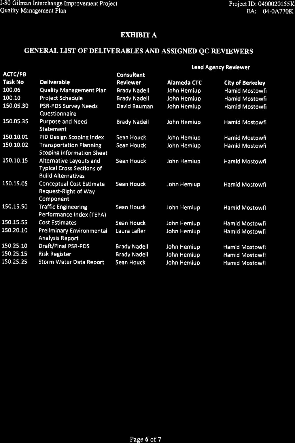
219
220