100 Design Controls and Exceptions
|
|
|
- Nicholas Goodman
- 5 years ago
- Views:
Transcription
1 100 Design Controls and Exceptions Table of Contents 100 Introduction Functional Classification General Urban & Rural Classification Used In ODOT Design Criteria Traffic Data General Traffic Data Content Terrain & Locale General Terrain Types Design & Legal Speed General Design Speed Values Design Exceptions General Design Controlling Criteria that Require a Design Exception National Network Local Projects Design Exception Documentation and Approval Process Documentation Format Processing and Approval Authority Amendments to Design Exceptions Crash Analysis General Applicable Projects Crash Analysis Crash Analysis Documentation... 8 List of Figures... 9 July 2018
2 100 Design Controls and Exceptions 100 Introduction In order to determine the criteria to be used for a project, it is necessary to initially identify some basic information about the facility. This information is known collectively as the design designation and includes: functional classification, traffic data, terrain, locale, design speed and legal speed. Figure shows how these design controls relate to many of the design features included in this manual. 101 Functional Classification General Functional classification, the systematic grouping of highways by the character of service they provide, is an important tool that has been used for many years in comprehensive transportation planning. Its adoption by highway designers to categorize basic highway systems serves as an effective transition from the planning process to the design process. Under a functional classification system, standards and level of service vary according to the function of the highway facility. Traffic volumes are used to refine the standards for each class Urban & Rural Functional classification is initially divided into urban and rural categories. Urban areas are comprised of: (1) places with a population of 5,000 or more, that are incorporated as cities, villages, and towns but excluding the rural portions of extended cities; (2) census designated places with 5,000 or more persons; and (3) other territory, incorporated or unincorporated, included in urbanized areas. Extended cities are those cities whose boundaries include territory that is essentially rural in character (e.g., uncurbed pavement with open drainage, where a rural typical section would be more consistent with the existing roadway). Urbanized areas consist of one or more places (central places) and the adjacent densely populated surrounding territory (urban fringe) that together have a minimum population of 50,000. The urban fringe generally consists of contiguous territory having a density of at least 1,000 persons per square mile. Rural areas are those outside the boundaries of urban areas Classification Used In ODOT Design Criteria The rural and urban functional classifications are further defined for design purposes as follows: Interstate Other Freeways and Expressways Principal Arterial Roads (rural) and Streets (urban) Minor Arterial Roads (rural) and Streets (urban) Collector Roads (rural) and Street (urban) Local Roads (rural) and Streets (urban) July
3 100 Design Controls and Exceptions The functional classifications for streets and highways in Ohio are kept on record in the Office of Systems Planning and Program Management. 102 Traffic Data General Traffic data is the foundation upon which designs are based; consequently, it is important that adequate traffic data be available early in the development of a project's design. It is equally important that this data be coordinated within various geographic regions of the State to avoid inconsistencies between projects under the same traffic influences. All forecasted traffic data used shall be developed following state traffic forecasting guidelines provided by Division of Planning, Office of Statewide Planning & Research, Modeling & Forecasting section. Documents containing forecasting guidelines are available on the office internet web page Traffic Data Content The design criteria tables in this manual require basic traffic data for the design year. The traffic design year is generally considered to be the following: Project Type New Construction Reconstruction Major Pavement Rehab. Minor Pavement Rehab. Two-Lane Resurfacing Traffic Design Year (After Opening Day) 20 years hence 20 years hence 20 years hence 12 years hence 12 years hence For most projects, the following data are required: Average Daily Traffic (ADT) for opening day (for lighting and signal warrants). Average Daily Traffic (ADT) for design year. Design Hourly Volume (DHV). AM and PM DHV are required for interchange design. The percentage of B and C trucks (T24) during the 24-hour period for the design year. The percentage of B and C trucks (TD) during the design hour traffic for the design year (for adjusting capacity analyses). Directional Distribution Factor (D) for the design year (used to obtain the Directional Design Hour Volume (DDHV) for the design hour). Projects on low-volume facilities (current ADT<400) without a design year traffic forecast may use the current ADT for design purposes. Average Daily Traffic (ADT) volumes should be subdivided into the following classes: P - Passenger Cars - including station wagons, mini-vans, sport utility vehicles and motorcycles. July
4 100 Design Controls and Exceptions A - Commercial - including motorized recreational vehicles, school buses, and light delivery trucks such as panel trucks and pick-up trucks which do not use dual tires. B - Commercial - including tractors, trucks with semi-trailers and truck-trailer combinations. C - Commercial - including buses or dual tired trucks having either single or tandem rear axles. Estimated Design Year ADT may be subdivided into P & A vehicles and B & C trucks if data for each vehicle class is not readily available, since these classes have similar operational characteristics. Current ADTs for various sections of Interstate, United States and State Highways for each county are available in the Traffic Survey Report published by the Office of Technical Services. Counts at specific points in the section may vary from the average and are available upon request from the Office of Technical Services. 103 Terrain & Locale General Many rural design features are significantly influenced by the topography of the land through which the roadway is constructed. To characterize variations, Ohio topography is categorized into three types of terrain: level, rolling or hilly. Locale is used to describe the type of area and generally refers to the character and extent of development in the vicinity. Urban, rural, residential, and commercial/industrial are characteristics often used to describe locale Terrain Types Level - Any combination of grades and horizontal and vertical alignment permitting heavy vehicles to maintain approximately the same speed as passenger cars. This generally includes grades of no more than 2 percent for a distance of no more than 2 miles. Rolling - Any combination of grades and horizontal and vertical alignment causing heavy vehicles to reduce their speeds substantially below those of passenger cars, but not causing heavy vehicles to operate at crawl speeds. Hilly - Any combination of grades and horizontal and vertical alignment causing heavy vehicles to operate at crawl speeds. Hilly terrain in Ohio conforms to mountainous terrain used in the American Association of State Highway Transportation Officials (AASHTO) publications. For design purposes a heavy vehicle is defined as a vehicle with a mass/power ratio of approximately 200 lb/hp. This represents a typical semi-truck. Crawl speed is the maximum sustained speed that a heavy vehicle can maintain on an extended upgrade and varies with the weight of the vehicle and the steepness of the grade. July
5 100 Design Controls and Exceptions 104 Design & Legal Speed General Design speed is defined in the AASHTO publication, "A Policy on Geometric Design of Highways and Streets" (Green Book), as a selected speed used to determine the various geometric design features of the roadway. The assumed design speed should be a logical one with respect to the topography, anticipated operating speed, the adjacent land use and the functional classification of highway Design Speed Values The minimum design speed for all projects shall be equal to or greater than the legal speed for the facility and the preferred design speed shall be 5 mph higher than the legal speed. Design speeds shall be specified in 5 mph increments. For resurfacing projects the design speed is the legal speed, or alternately, the 85 th percentile speed for individual or series of horizontal and vertical curves. Refer to part 1200 of the Traffic Engineering Manual for guidance establishing the 85 th percentile speed. Ramp design speeds are included in Section Design speeds of 50 mph and higher are considered high speed and design speeds less than 50 mph are considered low speed. 105 Design Exceptions General Designers and engineers are faced with many complex tradeoffs when designing highways and streets. A good design balances cost, safety, mobility, social and environmental impacts, and the needs of a wide variety of roadway users. Highway design criteria that have been established through years of practice and research form the basis by which roadway designers achieve this balance. These criteria are expressed as minimum dimensional values or ranges of values for various elements of the three-dimensional design features of the highway. The criteria are intended to deliver an acceptable, generally cost-effective level of performance (traffic operations, safety, maintainability, and constructability). The criteria are updated and refined as research and experience increase knowledge in the field of highway engineering, traffic operations, and safety. A design exception is a documented decision to design a highway element or a segment of highway to design criteria that do not meet minimum values or ranges established for that highway or project. The minimum values or ranges of design criteria, also known as controlling criteria for design, that require design exceptions when they are not met or exceeded are set forth in Section and Figure The designer should call attention to any design features that require a design exception as soon as possible, but no later than the first stage review submittal as defined in the Location & Design Manual, Volume Three. Other design values, policies, practices, etc. that are mentioned in this Manual are guidelines intended to promote uniformity and good design. Deviation from these guidelines does not require a formal design exception; however, it may still be necessary to justify or otherwise seek approval from ODOT of the July
6 100 Design Controls and Exceptions proposed design when deviations are necessary. This should be accomplished through the normal review process. Ramps do not have continuous design speeds throughout their lengths. However, design exceptions are required for not meeting the lower range for speed related items (see Section for directional and loop ramps). In addition, design exceptions for non-speed related items (e.g., lane width, shoulder width, bridge width, and lateral clearance) are required. A design exception should be reevaluated if the project has not sold within five years of the approved design exception. Exceptions will not be required for projects that do not change the basic highway cross-section or geometry; e.g. resurfacing, bridge deck overlays, rest areas, lighting, signing, signalization, fencing, guardrail, slide corrections, etc. A change in the basic highway cross section would include any change to the lane width, shoulder width, pavement cross slope or additional earthwork beyond the graded shoulder. Side roads with more than 600 of approach work do require design exceptions Design Controlling Criteria that Require a Design Exception Exceptions must be processed for the following design controlling criteria when they will not be attained: High Speed Roadways (Interstate highways, other freeways and roadways with a design speed 50 mph) 1. Lane Width 2. Shoulder Width 3. Horizontal Curve Radius 4. Maximum Grade 5. Stopping Sight Distance (Horizontal and Crest Vertical Curves) 6. Superelevation Rate 7. Vertical Clearance 8. Pavement Cross Slope 9. Design Loading Structural Capacity Low Speed Roadways (design speed <50 mph) 1. Design Loading Structural Capacity 2. Lane Width (only if required for the National Network, see Section below) In addition to the above geometric design features, design exceptions are also required when existing nonstandard bridge parapets and curb configurations are to be retained. For details on non-standard bridge parapets see ODOT Bridge Design Manual, or contact the Office of Structural Engineering National Network (or National Truck Network) The National Network was established by Congress in 1982 with the Surface Transportation Assistance Act as the network of highways designated for use by large trucks. In Ohio, the National Network consists of all Interstate Routes and the old Federal Aid Primary (FAP) Routes. One of the criteria for the National Network is, The route consists of lanes designed to be a width of 12 feet or more or is otherwise consistent with highway safety. In lieu of providing 12 lane widths for all lanes on the National Network, a single 12 lane in each direction can be provided or a design exception for lane width when the 12 lane in each direction cannot be provided. The lane width design exception would be required regardless of whether the facility is low or July
7 100 Design Controls and Exceptions high speed. The emphasis of the lane width design exception shall be the impacts to truck traffic such as truck involved crashes (existing and expected), truck off-tracking, etc Local Projects Design exceptions for Local-let projects should follow the guidelines in the Local Programs manual on Project Development and Design. Design exceptions for Local ODOT-let projects should follow the L&D Manual. The design exception format for both should follow section All Local project (both Locallet and ODOT-let) design exceptions are approved by the District Capital Programs Administrator Design Exception Documentation and Approval Process Documentation Format The Design exception document must contain at least the following information: 1. The Design Designation for the project. 2. A Title Sheet Location map and a schematic or plan sheet if needed for clarity. 3. The controlling criteria affected by the proposed design exceptions. (As noted in Figure 105-1, normal design criteria must be used as the basis for all design exceptions.) 4. A description of the project. 5. Proposed mitigation for the deviation (if any). 6. Support for the proposed deviation based upon sound engineering practices, cost comparison/ analysis, impact on the environment, the relationship between any crash patterns and the proposed design exception, etc. 7. The GCAT/CAM Tool must be attached Processing and Approval Authority 1. All design exception requests shall be prepared or processed by the District using the electronic submission process found on the Office of Roadway Engineering website, Design exceptions must be prepared and sealed by a licensed professional engineer. 2. Design Exceptions for projects in the LPA process will be approved by the District Capital Programs Administrator. 3. All non-local project Design Exceptions will be approved by Administrator of the Office of Roadway Engineering. The Office of Roadway Engineering will coordinate with FHWA for all projects requiring FHWA approval. 4. The Office of Roadway Engineering will be advised in writing of the action taken by the FHWA on Federal oversight projects. The original of such correspondence will be retained by the Office of Roadway Engineering and copies will be forwarded to the District. The District shall advise all involved LPAs and the Office of Estimating. July
8 100 Design Controls and Exceptions 5. All exceptions to the 16 vertical clearance standard on rural interstate routes or on a single interstate route through urban areas must be coordinated with the Surface Deployment and Distribution Command Transportation Agency (SDDCTEA) by the District. For details refer to the FHWA Memorandum of April 15, 2009 ( Amendments to Design Exceptions A previously approved design exception may be amended to accommodate additional elements (that do not invalidate previously approved items) by submitting an addendum to the design exception. The original may be amended to change previously approved items or remove items that no longer require an exception by submitting a revision to the design exception. In either case, the procedure follows the same formatting and approval process as the original design exception. 106 Crash Analysis General The purpose of the Crash Analysis is to determine if there is a pattern or concentration of crashes within the project limits that can be reasonably and practically addressed through the inclusion of countermeasures in the project. Factors that can affect countermeasures being reasonable and practical include but are not limited to: 1. Cost; 2. Environmental or R/W impacts; 3. Countermeasure work type being compatible with the planned project; 4. Schedule impacts The Crash Analysis should typically be performed in the early phases of project development such as during project programming. This will allow schedule, scope and budget considerations to be accounted for when reasonable and practical countermeasures are to be included in the project Applicable Projects Crash Analysis is applicable to ODOT let projects except those whose primary purpose is maintenance and as noted below. Local let LPA projects are exempt from performing the Crash Analysis. Typical projects where the Crash Analysis is applicable: a. Widening & Lane Additions (through and turn lane); b. Reconstruction; c. New Bridge Decks; d. Bridge Overlays; e. Resurfacing/Mill-Fill; f. Traffic Signal Installations and Upgrades; g. Projects where the existing cross section is being changed Typical projects where the Crash Analysis is not applicable: a. Maintenance projects such as guardrail repair, mowing, striping, signing, RPM s, etc.; b. Pavement surface treatment projects as defined by Section 550 of the Pavement Manual; c. Spot repairs; d. Slot paving; e. Projects where the Safety has already been reviewed (Safety Studies, Feasibility Studies, etc.) July
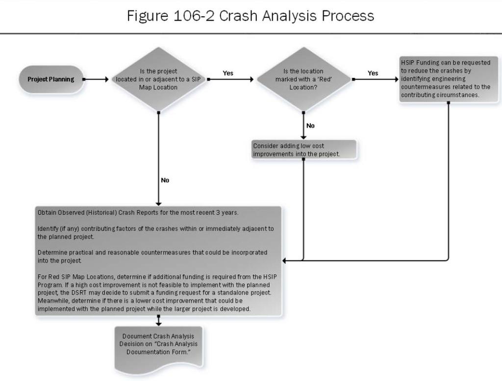
9 100 Design Controls and Exceptions Crash Analysis The Crash Analysis is based upon two sources of information: 1. The Safety Integrated Project (SIP) Maps The Sip Maps utilize HSM methodologies to highlight sections and intersections with a potential for crash reductions. Locations of interest are highlighted in either blue or red. a. SIP Map locations highlighted in blue are lower priority with the potential to reduce 3-5 crashes per year. Low cost countermeasures funded by the project may be appropriate for these locations. b. SIP Map locations highlighted in red are higher priority with the potential to reduce 5 or more crashes per year. Low or higher cost countermeasures may be appropriate for these locations. High Priority (red) locations may be eligible for supplemental project funding by the ODOT Safety Program to implement reasonable and practical countermeasures. i. Supplemental funding requests of $500,000 or less may be made at any time by the DSRT utilizing the SIP Map Abbreviated Safety Application (Refer to Figure 106-1). ii. Supplemental funding requests in excess of $500,000 will require application during the normal bi-annual safety funding cycle. c. Refer to the Office of Program Management web site for SIP Maps and the SIP Map Abbreviated Safety Application form. 2. GCAT/CAM Tool The second source of information highlighting potential crash locations or patterns of interest is the GCAT/CAM Tool. The GCAT/CAM tool should be for the 3 most recent years. A GCAT/CAM Tool should be run encompassing approximately 250 in advance and past the project limits. Locations or patterns noted solely based upon the GCAT/CAM Tool (i.e., not a red SIP Map location) should typically be considered low priority. Low cost countermeasures funded by the project may be appropriate for these locations. The district should evaluate the project limits based upon the SIP Maps and GCAT/CAM Tool. Where in the opinion of the district there is a noteworthy location or pattern of crashes, a determination should be made if there is a reasonable and practical countermeasure(s) that can be incorporated into the project. Refer to Figure for Crash Analysis Process. For high priority locations (red) there may be situations when there are reasonable and practical countermeasures but they can t be incorporated into the project due to factors such as schedule or work type incompatibility. In these cases consideration should be given to creating a standalone safety project to address the high priority (red) location Crash Analysis Documentation There is no specific requirement to incorporate countermeasures into a planned project. Rather, projects should be evaluated to determine if there is a reasonable and practical countermeasure(s) that can be incorporated into the project. Decisions related to the Crash Analysis should be documented on the Crash Analysis Documentation form (Refer to Figure 106-3) and retained with other project documents. July
10 100 Design Controls and Exceptions List of Figures Figure Date Title October 08 Design Control/Design Feature Relationship July 2016 Appropriate Design Criteria Guide July 2016 SIP Map Abbreviated Safety Application July 2016 Crash Analysis Process July 2016 Crash Analysis Documentation Form Samples Design Exception Request January 2017 July
11 100 Design Controls and Exceptions July
12 DESIGN CONTROL/DESIGN FEATURE RELATIONSHIP 100-1E REFERENCE SECTION DESIGN CONTROLS DESIGN FEATURES Functional Classification Traffic Data Terrain Local Design Speed Lane Width (Rural) X X X X Lane Width (Urban) X X Shoulder Width &Type (Rural) X X Shoulder Width & Type (Urban) X X Guardrail Offset X X Degree of Curvature X X Grades X X X X Bridge Clearances (Horizontal & Vertical) X X Stopping Sight Distance X Passing & Intersection Sight Distances X Decision Sight Distance X Superelevation X X Curve Widening X Design Speed (Rural) X X X Design Speed (Urban) X X Vertical Alignment X X X X Horizontal Alignment X X July 2013
13 APPROPRIATE DESIGN CRITERIA GUIDE 105-1E REFERENCE SECTION & Key Highway Design Features Requiring Design Exceptions Section Normal Design Criteria (1) Figure Lane Width & & -4, Shoulder Width & & -4, Design Loading Structural Capacity See Bridge Design Manual Horizontal Curve Radius Maximum Grade Stopping Sight Distance (Horizontal & Crest Vertical Curve) , 203-3, -4 Pavement Cross Slope Superelevation Rate , & , -7 thru -10 Vertical Clearance , -2, -3 1) Normal design criteria must be used as the basis for all design exceptions. July 2016
14 SIP MAP ABREVIATED SAFETY APPLICATION 106-1E REFERENCE SECTION SIP (Safety Integrated Projects) Map Form Project Information PID District County NLFID Begin Log point End Log point Begin Latitude/Longitude (example format: , ) End Latitude/Longitude Cost Estimate Construction Funding Year Description of Project Fill in Crash Summary* Fill in *Please attach a CAM Tool Excel file with submission July 2016
15 July 2016
16 July 2016
17 CRASH ANALYSIS DOCUMENTATION 106-3E REFERENCE SECTION PID County-Route-Section A. Do the project limits include a high priority (red) location(s) Y/N B. Do the project limits include a low priority (blue) location(s) Y/N C. Does the GCAT/CAT Tool show a crash pattern of interest Y/N Note: if the answer to all of the above is no this form is complete and no further documentation is required. GCAT/CAM Tool Summarize noted crash patterns and contributing circumstances (if any): Proposed safety countermeasures incorporated into the project (if any): Potential safety countermeasures to address noted patterns: July 2016
18 Below is Only Applicable if (A.) is YES 1. The High Priority SIP Map location(s) are addressed by this project with the above proposed countermeasures. 2. The countermeasures necessary to address the High Priority SIP Map locations are not practical and/or cost effective. Describe why the countermeasures are not practical and/or cost effective (may include but not limited to financial, R/W, environmental, etc.) in the box below. 3. Supplemental safety funding was requested and denied to implement the proposed countermeasures with the project. 4. It is not practical to implement the proposed countermeasures with this project. The safety countermeasures have been given to the DSRT for follow-up as a potential standalone project. 5. This project is an ODOT Let Local Project. It is not practical to implement the potential countermeasures into the project. The local agency has been made aware of the possibility to request funding for a separate safety project. 6. This project is an ODOT Let Local Project. The local agency declined to implement proposed safety countermeasures. July 2016
19 Additional supporting information for checked boxes (if needed): Prepared by: Date: July 2016
 4,310 Td 0 Design Year ADT (2035) 4,840 Design Speed 55 Design Hourly Volume (2016) 460 Legal Speed")
20 Design Exception Request SCI PID: Letting Type: ODOT-Let Design Designation Current ADT (2016) 4,310 Td 0 Design Year ADT (2035) 4,840 Design Speed 55 Design Hourly Volume (2016) 460 Legal Speed 55 Directional Distribution 0.57 Design Functional Class 5 Trucks (24hr B&C) 0.05 Functional Class Area Type Urban NHS Project No January 2017
21 Submitted by: (Engineer of Record) Approved by: Design Exception Request SCI PID: Controlling Criteria Identification Controlling Criteria Standard Existing (a.) Proposed Lane Width Shoulder Width Horizontal Curve Radius 955 Maximum Grade SSD (horizontal & Crest Vertical) Superelevation Rate Pavement Cross Slope 495 Curve ; Curve Curve ; Curve Curve ; Curve Curve ; Curve Curve ; Curve Curve ; Curve Curve ; Curve Vertical Clearance Design Loading Structural Capacity (a.) Existing may be N/A (i.e. New alignment or new ramp) Project Description The proposed project will improve safety by widening the lane and shoulder width and improving the stopping sight distance by increasing the guardrail offset through the reverse horizontal curves. January 2017
22 Proposed Mitigation Oversized curve warning signs, chevrons and arrow signs were installed in 2011 and will be reinstalled with this project. Flashing beacons will be installed on the two curve signs and the two arrow signs for Curve 2. Support for Deviation (Benefit-cost, R/W, Environmental, Constructability, Coordination with Other Projects, Relationship between any crash patterns and proposed design exception, etc.): The lane width is being increased from 11.1 to 12 and the paved shoulders are being increased from 2.8 to 4. To correct the horizontal alignment, the roadway would need to be relocated through a sizable hill with cuts as deep as 31. January 2017