LAYING OUT THE OVERHEAD CONVEYOR SYSTEM
|
|
|
- Elaine Randall
- 5 years ago
- Views:
Transcription
1
2
3
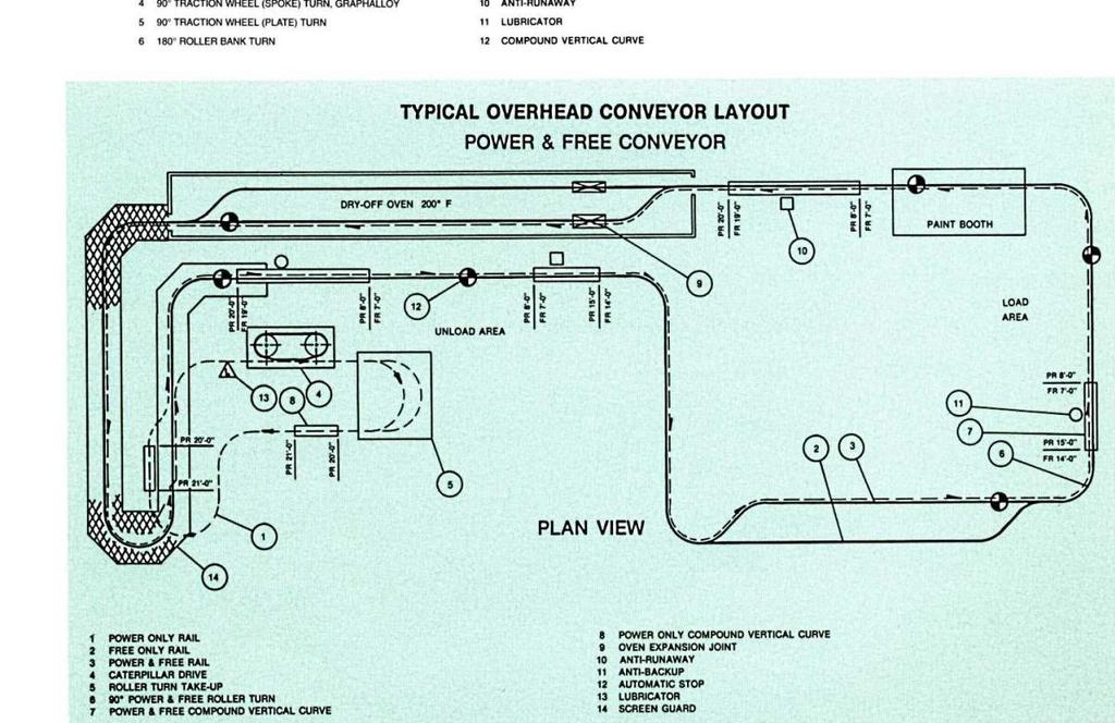
4 LAYING OUT THE OVERHEAD CONVEYOR SYSTEM Following is a step by step guide that is offered as just that, a guide, and is not intended to be an engineering manual. For a well engineered overhead conveyor system, especially a Power & Free System where subtleties of design and execution are not immediately apparent, it is recommended that an engineer skilled and experienced in overhead conveyor installations review your layout. Rapid Industries offers this service at no obligation and does not offer assurances or warranties that a conveyor system designed and installed without a review will perform satisfactorily. STEP 1 Draw Plant Layout STEP 11 Maximum Conveyor Speed STEP 2 Material Flow STEP 12 Conveyor Length STEP 3 Design a Carrier STEP 13 Moving Load STEP 4 Conveyor Size STEP 14 Lift Load STEP 5 Track Elevations STEP 15 Chain Pull STEP 6 Select Vertical Curves STEP 16 Select Drive STEP 7 Select Horizontal Curves STEP 17 Summary STEP 8 Guard Requirements ERECTION STEP 9 Required Carriers Per Minute SAFETY STEP 10 Trolley Spacing STEP 1 DRAW PLANT LAYOUT A. Layout on grid paper to largest practical scale (¼ =1, etc.) the plan of the plant in which the overhead conveyor will be installed. Indicate North direction of building. B. Draw an elevation view of the plant area where conveyor is to be erected. Establish the size and elevation of building construction from which the conveyor is to be supported. Indicate with section lines on plan if elevations are N, E, S or W. C. Locate and label all obstructions in the route of the conveyor such as columns, machinery, walls, work areas and aisles in plain view; duct work and pipe lines on the elevation views. STEP 2 MATERIAL FLOW A. On plant layout, locate load/unload points and processing stations served by the conveyor. B. Draw conveyor route so that it connects all areas in their proper work sequence with the most economical path for the system. Keep parallel conveyor routes as closely spaced as possible to reduce the amount of supporting members and guards required. Avoid using horizontal curved sections of track in an incline or decline. C. Be sure conveyor path does not interfere with machine operations or work areas. D. Indicate location of drives, vertical curves, horizontal turns, relative to column lines. Refer to typical layout, conveyor symbols, and glossary if needed. STEP 3 SELECTING A CARRIER A. Typical examples of carrier designs are shown in Carrier Section. B. Determine number of parts to be placed on each carrier and their relative position on carrier. Make carrier as compact as possible. C. Design of carrier should permit easy loading and unloading of parts. D. The carrier should be designed to carry loads within the rated capacity of the trolley. Avoid eccentric loading of carrier. Ideally, the carrier with load should always hang plumb. Trolley capacities are listed in the Trolley and Attachment Section. E. Carrier bracket is to be designed to fit a chain attachment to which the load or carrier can most readily be attached. F. Standard trolley attachments may be selected from the data and illustrations in the Trolley and Attachments Section. Almost any type of attachment can be furnished.
5 STEP 4 CONVEYOR SIZE A. Select a trolley arrangement from the Trolley and Attachment Section that has a capacity rating exceeding the total weight of the carrier designed in Step 3 and the carrier load. B. The trolley load carrying capacity will determine the size of the conveyor in the average conveyor application. However, the chain pull as calculated in Step 7 must not exceed the recommended working load for the size chain as shown in the Chain Section. STEP 5 TRACK ELEVATIONS A. Elevations are measured from floor line to top of I-Beam track. B. At loading / unloading areas, the conveyor height should permit a person to easily load and unload the carrier if this is to be a manual operation. If loading / unloading is to be automatic, provisions should be made for the installation of this equipment. C. Accepted clearance over work areas and aisles is 7 from floor to lowest obstruction. Conveyor height over aisles where trucks are used must allow traffic to pass freely. D. To determine where guards should be installed, refer to Guard Section. E. Indicate elevations at all vertical curves. See typical conveyor layout in the Design Guide. STEP 6 SELECT VERTICAL CURVES A. For increased conveyor life, use largest recommended radius possible for vertical curves in layout. Use minimum radius vertical curves only in conveyor areas where necessary. B. Using Figure 1, select a degree of incline for vertical curves that will provide a clearance between carriers when they are moving on the incline. To assure clearance between carriers, dimension A must be greater than carrier length. C. Select load spacing. D. Because of carrier sway, clearance must be provided between top of carrier and conveyor chain. E. Select vertical curves from Vertical Curve Section. F. Indicate the horizontal length of each vertical curve, its radius and degree. G. Locate each vertical curve relative to some adjacent component, as shown on typical layout following the overhead conveyor schematic in the Design Guide.
6 STEP 7 SELECT HORIZONTAL CURVES A. Make a plan view layout of horizontal turn as shown in Figure 2. Clearance between adjacent carriers while negotiating turns will determine minimum horizontal turn radius. B. For increased conveyor life, use the largest standard radius possible for horizontal turns in your layout. Select the horizontal turns best suited to your requirements from the Roller Turn or Traction Wheel Section. C. Provide for one (1) 180 degree horizontal turn in your layout, as near as possible on the output side of the drive unit, for use as a slack chain take-up. Refer to Take-up Section. If possible, place this take-up at the bottom of a vertical curve. STEP 8 GUARD REQUIREMENTS A. For standard guard methods, refer to Guard Section. B. Select type of conveyor guard best suited to your requirements. C. Be sure loaded carriers will clear all guards. 6 clearance on each side is usually sufficient. It is also important to check clearances on horizontal and vertical curves. D. Locate each guard relative to adjacent conveyor component or column line on layout. STEP 9 REQUIRED CARRIERS PER MINUTE A. Determine how many parts are to be handled per minute. B. The following example illustrates the proper procedure to determine number of carriers per minute based on the parts capacity of the carrier. a. Assume your production rate is 2400 pieces per hour. b. Assume each carrier holds eight (8) parts. c. Required number of carriers per hour equals 2400 / 8 = 300 carriers. d. Required number of carriers per minute is 300 / 60 = 5 carriers. STEP 10 TROLLEY SPACING A. Refer to Step 6, letters C, D, and E and Step 7, letter A. Note the carrier spacing selected for proper clearances. B. Refer to Trolley and Attachment Section and note maximum spacing for trolleys. C. If your required carrier spacing is greater than the recommended trolley spacing, intermediate trolleys are required. D. When laying out the conveyor path, a distance equal to the maximum trolley spacing should be allowed between tangent lines of vertical and horizontal turns.
7 STEP 11 MAXIMUM CONVEYOR SPEED A. A speed of per minute is normally considered as maximum. 30 per minute usually allows easy loading / unloading and assures longer conveyor life. B. Required conveyor speed in feet per minute is equal to the number of carriers per minute multiplied by carrier spacing in feet. To illustrate: a. In step 9 we determined that five (5) carriers per minute are required. b. Assume a carrier spacing of 24 or 2. c. Five carriers per minute multiplied by carrier spacing of 2, equals a conveyor speed of 10 per minute. C. To allow for variation in production requirements, it is advisable to set a maximum speed of about two times that calculated. A variable speed drive with a speed range of about 3 to 1 is the most economical. a. The maximum speed is 20 per minute. b. Using a 3 to 1 ratio variable speed drive would give you a speed range of 6.6 per minute to 20 per minute. D. Refer to Drive Section for variable and constant speed drive information. STEP 12 CONVEYOR LENGTH A. Obtain the sum of all straight track dimensions. B. Obtain the sum of all arc lengths on the horizontal turns by using the horizontal turn lengths and take-up length in the Roller Turn and Traction Wheel Turn Sections. C. Obtain the sum of all arc lengths and tangents including incline straight track on the vertical curves by using the vertical curve formula in the Vertical Curve Section. D. The total length of the conveyor is equal to the sum of above. When ordering chain for the conveyor, ad 3% or a minimum of 10 to the total length. STEP 13 MOVING LOAD A. The moving load on a conveyor is equal to the sum weight of all moving parts; chain, trolleys, carriers and loads. B. Establish distances from loading to unloading points and determine the number of loaded and empty carriers in the system during maximum capacity of conveyor. C. The following example illustrates the procedure for determining moving load assuming the conveyor is 600 feet long, carriers are at 2 centers and distance from loading to unloading points is 500 feet. a. 600 feet X-458 chain at 3.1lbs per foot 1,860lbs. b. 300 trolleys at 7.5lbs each 2,250lbs. c. 250 loaded carriers at 125lbs each 31,250lbs. d. 50 empty carriers at 10lbs each 500lbs. STEP 14 LIFT LOAD A. The lift load is the amount of force required to pull the moving load upward along the vertical curves in the entire system. B. To calculate, determine the difference in elevation of all loaded vertical curves traveling upward in the system. This vertical rise is considered the total lifting height of the conveyor. C. The lift load or chain pull for the elevation changes of the conveyor is: (total lift height in feet) x (individual load weight in pounds) / (load spacing in feet) Example: Assume that there are three vertical curves traveling upward: (total rise height of 15 ) x (125lbs. loads) / (2 centers) (15 x 125) / 2 = 938lbs D. A loaded conveyor moving up an incline requires a certain amount of continuous force which is compensated by a loaded decline further along the conveyor and can be ignored. Starting conditions often impose an exception since at the start of production when conveyor is first loaded, inclines could be loaded without loaded balancing declines.
8 STEP 15 CHAIN PULL A. Chain pull is the effort necessary to maintain the normal operating speed of a conveyor under a rated capacity load. It is necessary to add the lift load and the friction factors which act as a resistance to the progress of the conveyor. The moving load and the lift load were calculated in Steps 13 and 14. B. Frictional resistance is found in the bearings of the trolley wheels, roller or traction wheel turns or drive unit itself. This is represented as a small percentage and listed in Figure 3. When adverse environmental conditions exist or the conveyor is abnormally long or complex and exceeds the chain pull capacity, a progressive chain pull computation is necessary where the friction losses are progressively calculated along the conveyor. C. Select from Figure 3 the friction factor indicated for your conveyor size. (Note: a larger number of vertical and horizontal curves will create slightly higher friction) FIGURE 3 - Friction Factors Ball Bearing Trolleys Temperature Range F (average conditions) 2¼% 2% 1¾% 1½% F (auto oil lubrication) 3½% 3% 2½% 2% F (special care) 7% 6% 3¾% 2½% Over 475 F (consult Rapid engineering) D. To determine chain pull due to friction, multiply total moving load by selected friction factor. Figures from previous examples illustrates proper procedure: 1. Total moving load (from Step 13) 35,860 lbs. 2. Multiply by friction factor (Fig. 3).025 Friction chain pull E. Add lift load to friction chain pull to obtain total chain pull lbs. 1. Friction chain pull lbs. 2. Lift load (from Step 14) 938 lbs. Total chain pull lbs. F. Refer to Chain Section and determine if chain size has sufficient capacity for required chain pull. STEP 16 SELECT DRIVE A. Refer to Drive Section of Rapid Industries Conveyor Catalog for features and speed of caterpillar and sprocket drives. Knowing your required speed and chain pull, select proper drive size. B. Locate the drive so it will apply a pulling force on the most heavily loaded portion of the system. (Note: The drive must pull, not push, the load) C. For best results, locate the drive at some high point in the conveyor system and place the take-up just after the drive at a lower point. D. Show selected drive and location on conveyor layout. Relate location to an adjacent component as shown in Typical Conveyor Layout at beginning of this section.
9 STEP 17 SUMMARY A. For quick reference, make a legend on your layout covering the following subjects: a. Speed of conveyor and direction of travel b. Length of conveyor c. Trolley spacing d. Carrier spacing e. Total number of carriers f. Number of parts on each carrier g. Weight of carrier h. Weight of part on carrier i. Moving and lift load j. Maximum chain pull k. Type, number and kind of drives selected; electrical specifications l. Guard cross section with dimensions (expanded metal, wire mesh or sheet drip pan type) B. Make a list of all components required to complete your conveyor system. The following is a suggested check list: a. Chain size and length b. Trolleys and attachments c. Carriers d. Roller turns e. Traction wheels f. Take-ups g. Drive h. Horizontal turns (degree and radius or pitch diameter) i. Vertical curves (degree and radius) j. Switches k. Guard material C. Contact your Rapid Industries sales engineer as they have wide experience on conveyor systems and components. Their services are available for surveying your plant, inspecting layout, or assisting in placing order. ERECTION If you have the necessary equipment and facilities to completely install your newly designed conveyor system, we refer you to the Installation Section of this Design Guide. Rapid Industries has a staff of competent installation superintendents and experienced crews. The Rapid Industries sales engineer in your area will be happy to procure for you the services of these experts in all phases of conveyor installation. SAFETY Determine whether your overhead conveyor layout conforms to your company s safety policies and is in compliance with State and Federal OSHA requirements. Are all required guards in place? Does electrical conform to code? Are there sufficient safeguards and controls with ready access to insure the ability to maintain safe working conditions under normal and emergency conditions?