THE DEVELOPMENT OF AN ALTERNATIVE LOADING METHOD FOR PIPE IN GONDOLAS. John Milkay United States Steel Corporation
|
|
|
- Nancy Clark
- 5 years ago
- Views:
Transcription
1 THE DEVELOPMENT OF AN ALTERNATIVE LOADING METHOD FOR PIPE IN GONDOLAS John Milkay United States Steel Corporation
2 Figure 124 has been an approved diagram for pipe loading since the 1940s Why the need for a new loading diagram now?

3

4

5

6 So, what has changed? The Railroads began installing WILD detectors to identify load issues that would detect the sources of premature wear of car components as well as reducing the possibility for a derailment. Wheel Impact Detector Coverage ( ) Vine Creek, IN Mill Creek, PA Middlesex, NJ (SA) State Line, IN ( 06) MP-B385.1 ( 07) Marion, OH ( 06) Marietta, PA ( 06) Waverly, VA MP-V220.1, Roanoke, VA ( 07) Flat Rock, KY MP-339.8, Charlotte, NC ( 07) Loudon, TN ( 07) Cherokee, AL ( 07) (8) Wheel Impacts (WILD, WCM) (5) Proposed WILD Sites 2007 (4) Proposed Alternate WILD Sites Core Routes

7

8

9

10 Now, let s look at SAFETY

11 WHY?

12 WHY?

13 WHY?

14 WHY?
15 The goal of the Railroad was to increase their efficiency and throughput as well as safety for the employees and communities through which they travel. Data suggests that a load of pipe moves approximately 18 inches each time a car is switched. In October, 2009 Circular Letter C came out, mandating a minimum three foot clearance from the end of the load to each end of the car. The letter gave pipe suppliers one year to comply. Again, why do we need a new loading diagram? API Range three casing is 48 maximum. The railcars we use are 52 long. The Clearance Rule would have affected operations resulting in decreased yield, reduced efficiency in production, and increased costs for couplings and thread protectors. These costs made USS start to look at alternative securement methods and loading scenarios.
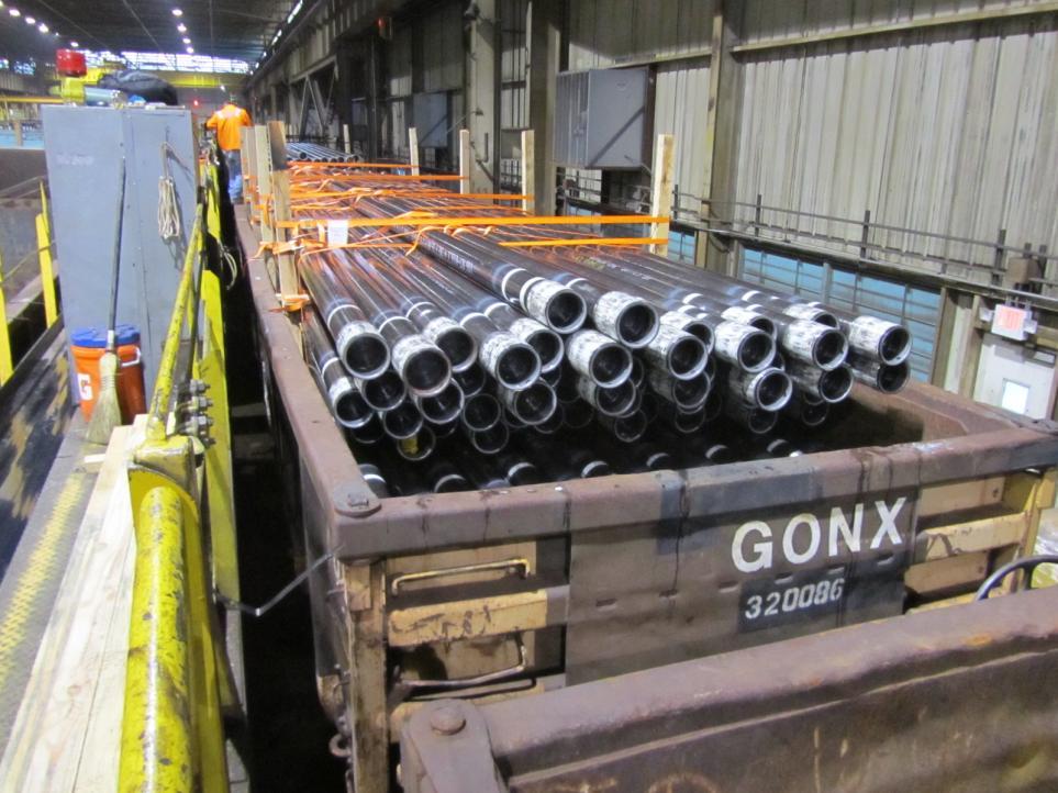
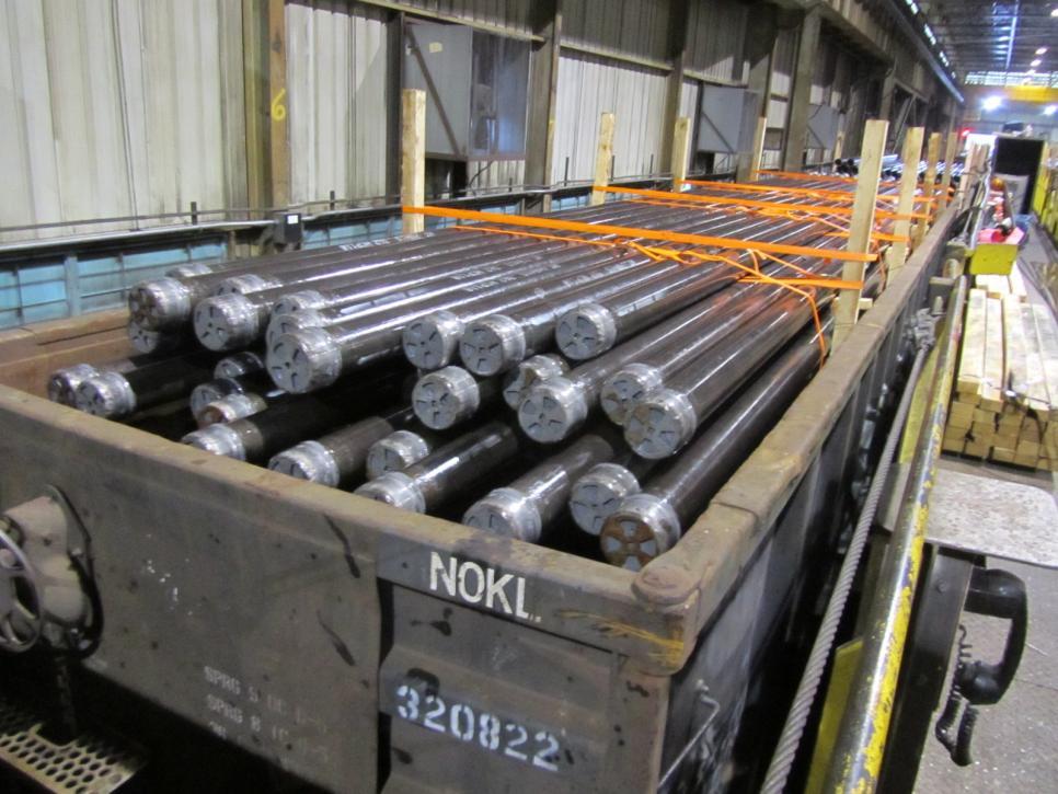
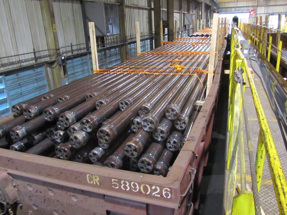
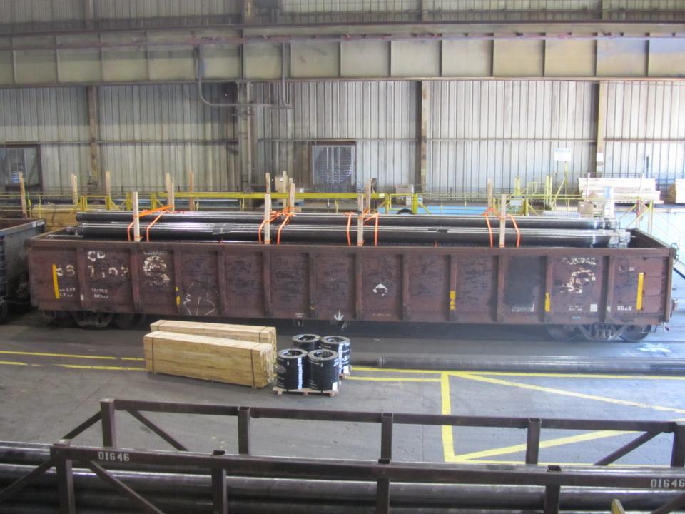
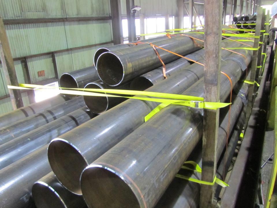
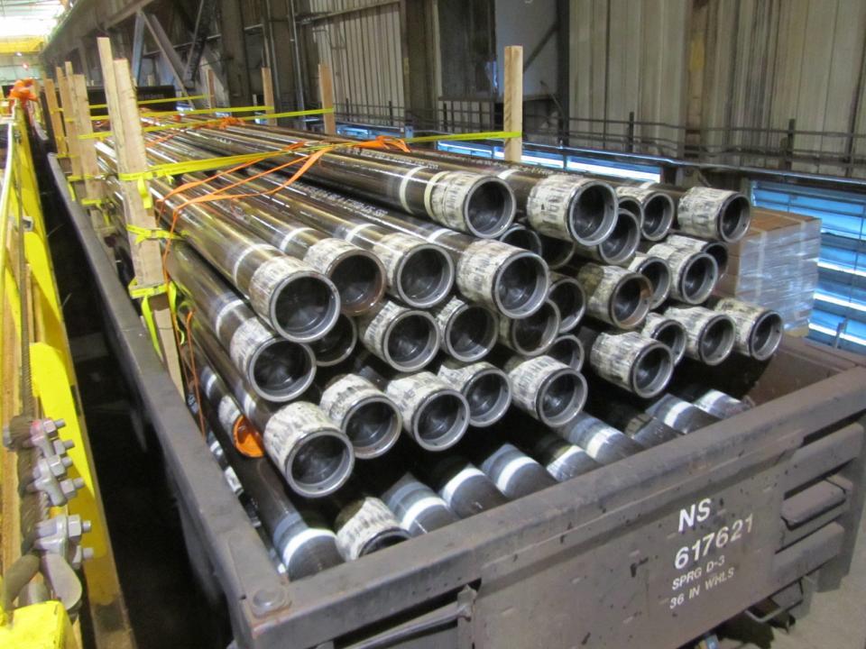
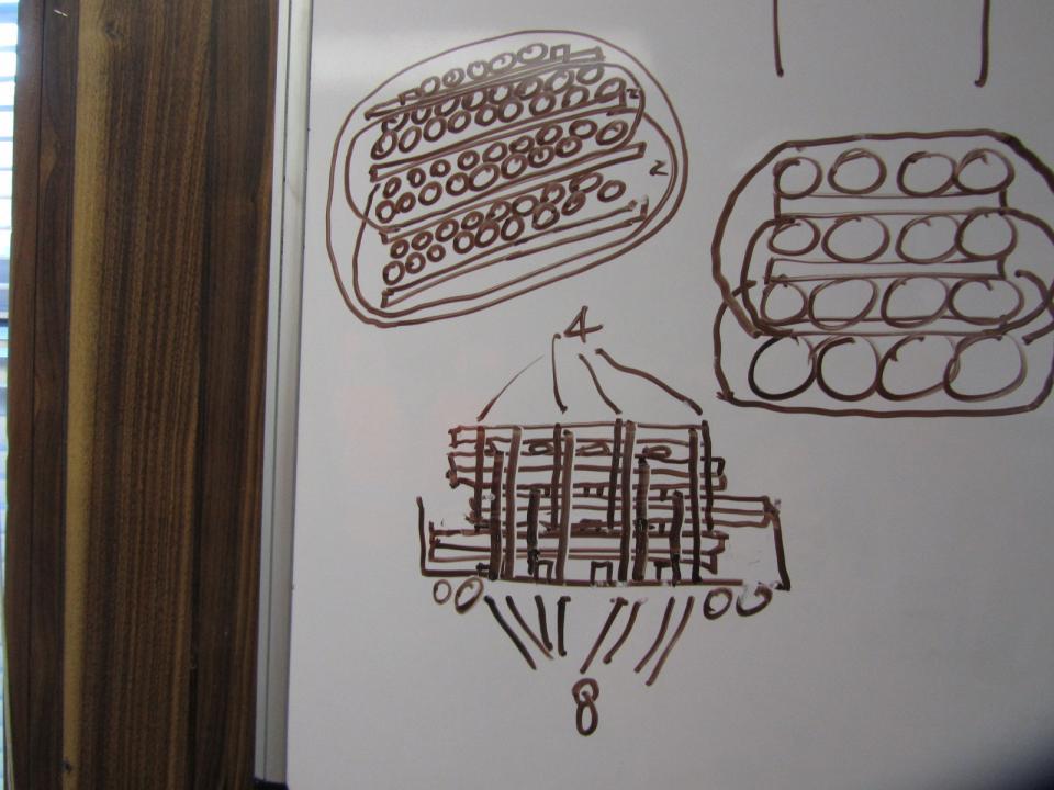
16 Potential Solutions Remove the Figure from the Rules. Stop cars from Foreign Roads at Interchange using visual inspection criteria (or reject them unless they have detector readings showing balanced load). Load no higher than the top chord of the car. Load short pipe in two piles in long car. Long pipe in single pile in short car. Secure top layer (above top of car) to car Tenaris Method. Stagger load end to end, with top layer centered and secured USS Method. Other methods have been tried and failed. Must be resolved as train delays, car set outs, significant premature wear to components that can lead to derailments must stop.
17 Based on the options that the Railroads offered, the most likely scenario that would have been imposed was the Clearance Rule coupled with not allowing shippers to load over the top chord of the railcars. So why do we need a new method of loading? Over 80% of the cars we load are significantly higher than the top chord of the car. If all shippers were forced to keep their loads at the top of the car, the demand for railcars would increase causing significantly higher freight charges. These costs cannot be passed on to the customers, resulting in lower profitability. An alternative to developing a new method of loading could be to ship by truck. However, there are not enough trucking companies out there to handle the sudden change over to this shipment method. The flat bed fleet just does not exist. Scheduling of trucks and the time it takes to load a truck made this an unattractive solution. Now we really need a new method of loading railcars!
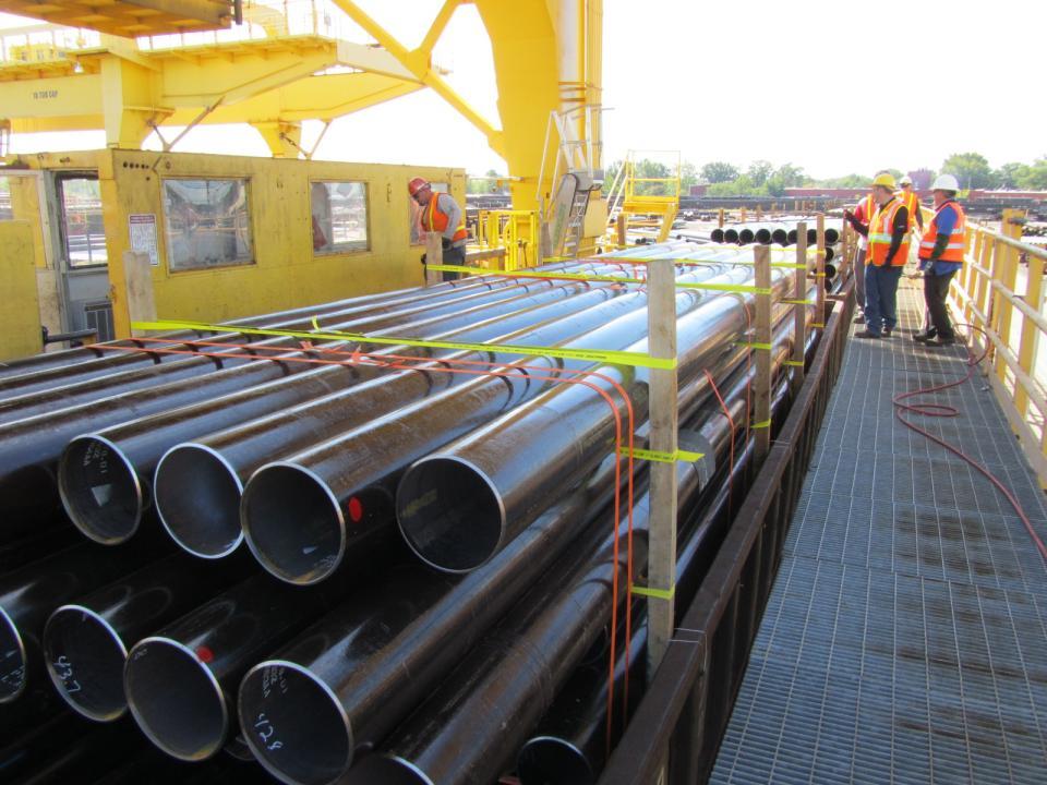
18 In 2010, USS began trials with various nylon strapping producers/suppliers to develop a better loading method. Why would a steel manufacturer not use steel banding? Quite simply, it does not work! The non-metallic strapping has memory, to remain tight even as the load settles through travel. Think of a rubber band around a handful of pencils. USS along with Carolina Strapping and Buckles Company tried many different configurations of interweaving the straps to get a good, non-movable load. Initial loads used upwards of 40 encircling and unitizing bands. Not only did these take too long to tie up, they still would not pass an AAR impact test. Based on the continued work by USS on developing an alternative loading method, the AAR suspended the restraints set forth in Circular Letter C The thought process turned to if we can keep the bottom of the load from moving and tie the top to the bottom, then the top of the load shouldn t move. This was the key to the success of the method. In 2011, the stagger method was implemented, along with the use of rubber friction matting to keep pipe to pipe surfaces from sliding.

19
20
21

22
23

24
25
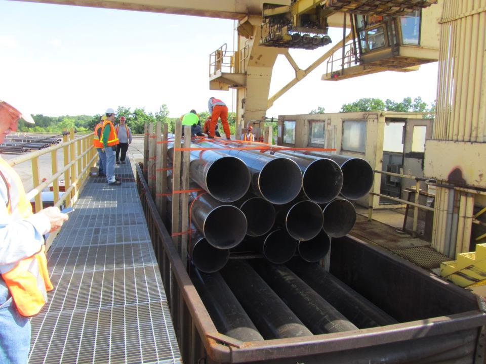
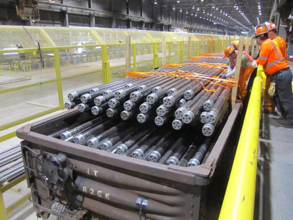
26 USS continued to perfect the loading method and sent trial cars over the road on a limited basis. The cars were tracked to destination to verify the results of the loading method. In March, 2012 USS attended the AAR Spring meeting in Charleston, SC and informed the AAR of our intent to continue trials with the intent of fully converting over Fairfield Tubular Operations to 100 non-metallic strapping. The AAR thanked us for the work we had been doing, and encouraged us to continue, as the results spoke for themselves. On May 16, 2012 Fairfield made the switch to loading all railcars using Carolina Strapping and Buckles Company s GatorLASH (AAR 80) and Allegheny Industrial Associates TransMat friction matting. Shipments were sent all over the country as well as to Canada using the USS method of loading. Of over 2000 cars shipped, we received reports of 4 setouts. All four were attributed to handling issues and not loading issues. I travelled in June, July, and August to some of our sister plants in Ohio and Pennsylvania to teach them the same method, adapting it to their particular loading techniques and equipment limitations.

27

28
29

30
31
32

33

34
35 In late August, the AAR granted USS an official 25 car over the road trial. The trial was to consist of forty cars, with 15 being from Lorain (large OD) and 25 from Fairfield. I went to Lorain to direct the loading of their cars.
36

37

38

39
40 Then, back to Fairfield to get our 25 cars on the rails..

41

42

43
44

45
46 Once the 40 test cars were all shipped, weekly conference calls were conducted with representation by USS, AAR, CSB, and AIA. Discussions revolved around the loads that were delivered and their condition, pending loads to be delivered, and the distances and switching the cars went through. Once a total of the 25 cars were delivered and documented, USS asked that the new loading method be incorporated into an official AAR Section 2 configuration. In December, the AAR Open Top Loading Rules Committee asked that the USS figure be sent to the Rules and Figures Committee for review. This, from what we understand, was through a unanimous vote of the OTLRC. On February 21, 2013 the AAR issued Circular Letter C acknowledging what is now known as Figure 124-A. The rest, as they say, is history.

47
48
49
50 Thank you for your time and allowing me to present today. Keep asking WHY.