In-process monitoring methodology
|
|
|
- Edmund Johnston
- 5 years ago
- Views:
Transcription


1

2 Repetitive manufacturing processes such as crimping and stamping exert force during the material forming process. The measured resistance during this material forming and compression process results in a characteristic force signature or pulse. The repeatability of this pulse is directly related to the capability of the process and the quality of the part produced. Monitoring the pulse of every machine cycle for repeatability is an effective method for assurance of quality of every part produced, and an indicator of the health of the process.
3 A healthy process is repeatable and will ensure quality parts are produced. An unhealthy process may continue to produce good parts but will contribute to quality issues, scrap material, maintenance issues, and machine downtime. Monitoring the pulse of the process is an effective method for assurance of part quality, and early detection of changing conditions in the process that might otherwise lead to quality issues, scrap, and unplanned machine downtime.
4 Each machine cycle involving force forming or joining of materials should result in a repeatable pulse Examples of conditions in the manufacturing process that can result in an irregular pulse include: Change in material hardness, shape, concentricity, coating Tooling wear or breakage Change in part dimension Misalignment or incorrect presentation and/or insertion of materials Degradation of the machine condition such as broken or loose components, loss of lubrication
5 Taking a closer look at the resulting force signature from a production part Time or position
6 Illustration of a force signature from a defective part Time or position
7 Illustration of a force signature from a defective part Time or position
8 The process trend - what is a good part, what is not
9 Illustration of process drift and degradation
10 Illustration of a random defect termed lightning strike
11 Process Stability

12 How the system controls defective and suspect parts Annunciates the defect condition to operator Stops machine automatically Part isolated for secondary inspection Logs and time stamps data from every production part Data can be transferred to USB stick or collected by plant Network


13 Typical system configuration MACHINE INTERFACE FOR CONTROL OF PART DEFECTS DYNAMIC PIEZO FORCE SENSOR CAPTURES THE FORCE DURING METAL FORMING PROCESS OPERATOR INTERFACE ANNUNCIATE DEFECT DISPLAY PROCESS TREND TOTAL PARTS PRODUCED SCRAP RATE PVM5000 CAPTURES ANALYZES THE AND FORCE ANALYZES SIGNATURE, THE DISCRIMINATES FORCE SIGNATURE, PROCESS VARIATIONS SENDS CONTROL THAT ARE OUPUT CHARACTERISTIC TO MACHINE OF PART DEFECTS, PASS/FAIL


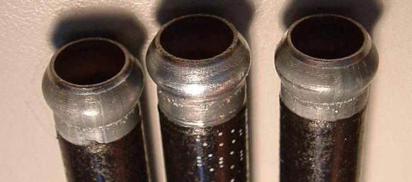


14 In-process monitoring Application - End forming & Hose Crimping


15 Current Inspection & QC Practices Dimensional measurement and/or physical Inspection of sample parts Catch gross part defects Prevent faulty parts from reaching the customer Inherent Shortcomings Detection of material flaws hardness, thickness, cracks Detection of hidden, non-visible defects Manual inspection processes with high dependence on operator Post process inspection adding time and costs Limited traceability
 Loss of lubrication Incorrect material presentation (insertion,")
16 In-process monitoring Capable to detect Change in part dimension Excessive variation or degradation in the process that will ultimately contribute to quality issues, increased scrap, and machine downtime: Tooling wear, gripper and/or guide wear Change in raw material quality or consistency (hardness, concentricity, coating) Loss of lubrication Incorrect material presentation (insertion, automatic and manual feed methods) Incorrect machine setup (misalignment issues, loose components, etc.) FORCE
 PRODUCTION PART SIGNATURE")
17 In-process monitoring Force signature from a production part The force signature profile from each production part is compared to the force signature profile of a reference good part LEARNED REFERENCE PART SIGNATURE (BLUE) PRODUCTION PART SIGNATURE (GREEN)
18 In-process monitoring Illustration of a good part. 3 1 INITIAL TOOL CONTACT TOOLING INSERT TUBE COLLAPSE & FORMING 1


19 In-process monitoring Illustration of a defective part. THE SHAPE OF THE SIGNATURE SHAPE HAS CLEARLY CHANGED IN REGION 2 & 3 AND DETECTED DURING THE TUBE FORMING PROCESS 1 INITIAL TOOL CONTACT TOOLING INSERT TUBE COLLAPSE & FORMING 1


20 In-process monitoring The product Central Data Base ETHERNET Sensor Interface -FORCE SENSOR -POSITION SENSOR PVM5000 Process Variation Monitor Equipment Control -MACHINE/PRESS Traceability -REAL TIME DATA LOGGING Part/WO Selection -BAR CODE READER Productivity Reporting -PRODUCTIVITY- -PRODUCTION -QUALITY Process CPK, Scrap Count
21 Benefits 100% monitoring of parts for assurance of quality Early detection of degrading process or machine conditions Eliminates the potential for human error Reduces the risk of generating unnecessary scrap Reduces the risk of supplying defective material to customer In-process monitoring does not reduce machine processing time Traceability 100% traceability of parts produced Automates and error proofs the monitoring of the process and part quality


22