Vibratory Feeder System REFERENCE MANUAL
|
|
|
- Muriel Gregory
- 5 years ago
- Views:
Transcription


1 Vibratory Feeder System REFERENCE MANUAL


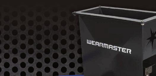
2 TM-HOPP Hopper / TM-VU Vibratory Feeder Unit TM-MCB Main Control Box TM-IC Interconnecting Cable TM-TH Silicon Dropper Hose 16mm TM-TB Torch Bracket M Dispensing Nozzle Power Inlet Socket / Serial Number TM-FP Foot Pedal 2 Wearmaster Reference Manual
3 VIBRATORY FEEDER SYSTEM This is an automated hardfacing system for dispersing tungsten carbide granules into a weld pool created by the mig welding process (GMAW). Included in this system are the following: Vibratory feeder/hopper assembly with remote control box. Integrated and removable carbide hopper. 1.33M (52 ) heat resistant 16mm feed tube. Stainless Steel vibrating feed chute. Zinc plated dispensing neck with replaceable nozzle (1 spare included). 115VAC / 230VAC option available. Foot pedal control switch (Current sensing reed switch option available). CONTROL FUNCTIONS AND DESCRIPTION OF SYSTEM Power is supplied to the system via 115VAC or 230VAC depending which option is purchased. A 1.5 and 1 Amp fuse protects the system and a red light illuminates when the system is powered on. The Interconnecting cable connects the control box with the main feeder. The POWER switch powers the controller on and off. The FLOW RATE dial controls the amount of carbide the feeder supplies. The higher the number, the higher the feed rate. A typical setting is somewhere between 4 and 6. AUTOMATIC / MANUAL MODE: A Toggle switch changes the MODE between Manual (MAN.) and Automatic (AUTO) functions. On MAN. the feeder will be activated and the carbide will flow until the control box is switched off or the MODE switch is returned to the AUTO position. Moving the switch to the AUTO position activates the switch circuit which enables the use of a foot pedal or reed switch to turn the feeder on and off. A foot pedal is included as part of the system package and reed switches are available as an optional part. The reed switch is a current sensing switch which can be attached to the welding earth lead, and automatically turns the feeder on and off when you start and stop welding. 3
4 FEED TUBE SETUP: It is important the Feed Tube remains relatively straight when welding. Once the tungsten carbide chip enters the Feed tube it is reliant on gravity to drop down into the weld pool. If the Feeder Unit is positioned 1.2 meters above the welding table then the usable table area would be approx. 1 square meter directly underneath the Feeder. ADDITIONAL INFORMATION ON WELDING WITH THE WEARMASTER SYSTEM SURFACE PREPARATION: Always clean the surface to be hardfaced with a buffing wheel, sanding or grinding disc. A clean surface will help ensure a good deposit is put down. WELDING WIRE: The most commonly used wire size is 1.2mm (.045 Dia) There are many different types of wire that can be used, but wires that develop a slag coating should not be used. The type of wires that give the best results are metal-cored types, especially High-Chrome/High-Carbon type s, and are typically used with higher than normal voltage settings to ensure the weld pool is fluid enough to allow the carbide to enter and correctly disperse. Voltage settings could typically be around volts for a 1.2mm (.045 Dia) wire. CARBIDE SIZING: The most common sizes of carbide used would be 14 x 20 mesh or 16 x 20 mesh but of course there are other sizes readily available as well. Talk to your nearest dealer for the correct size for your job. CARBIDE DEPOSITION: This depends on the type of wire and size being used. With a 1.2mm (.045 Dia) wire, gm/min of carbide would be a typical deposition rate. Accurate digital scales are recommended for checking the flow rate. Too much carbide flow is detrimental and will cool the molten weld-pool too quickly, as well as not allowing the weld matrix to fully encapsulate the carbides leading to chipping out or weld spalling. Conversely, too little carbide in the weld will cause premature wear results. 4 Wearmaster Reference Manual


5 SHIELDING GASES: Argon/Oxygen (2%) is a popular mix however 75% Argon 25% CO 2 is also commonly used especially if solid mig wire is being used. WELDING TECHNIQUES: Single layer welds are recommended as multi-layer welds have a tendency to melt the carbide in the lower layer which will produce a very hard weld deposit that then becomes prone to chipping or spalling out. A weave or oscillation is recommended from ½ - 1 wide, and even wider should the application call for it. The aim point for the carbide is critical and should be directed into the last ½ of the molten weld pool. Aiming too close to the arc will cause the carbides to melt causing a brittle weld structure. PRE-HEATING: This is largely determined by the type/composition and carbon content of the base material. High carbon steels like Chromoly and high strength low alloy types like Bisalloy, Wearalloy need preheat. The temperature that these materials will need to be heated to is also dependent on the thickness of the steel. A typical preheat temperature for GET (ground engaging tools) would be 150 degrees Celsius. We suggest calling us to discuss the job if you are unsure. SCREENING USED CARBIDE: Approximately only half the carbide flowing down the feed tube will enter the weld-pool so it is a good idea to collect the excess and re-cycle it. Sieves are available and are useful for removing dust, weld spatter and other impurities. 5

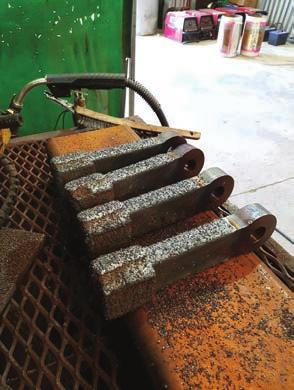
6 THE SETUP: 6 Wearmaster Reference Manual

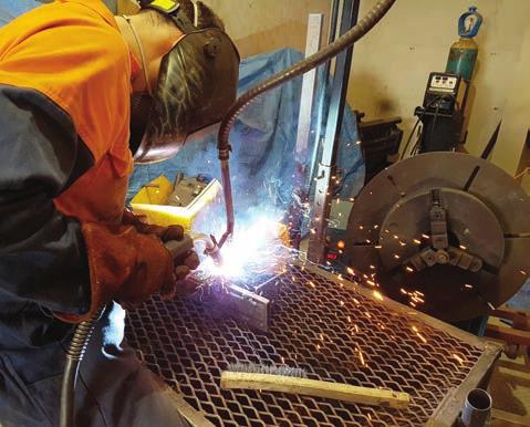
7 THE PROCESS: 7


8 Duralloy Industrial Supply 2 Hollylea Rd Leumeah, NSW, 2560 P: E: sales@duralloy.net.au