FOUNTAIN FLOW STANDARD INJECTION MOULDING. Mold Temperature Tg Polymer
|
|
|
- Nelson Magnus Burke
- 5 years ago
- Views:
Transcription
1 FOUNTAIN FLOW STANDARD INJECTION MOULDING Mold Temperature Tg Polymer Polymer Melt Instantaneous Frozen Skin Layer As the molten polymer enters the cavity and comes into contact with the (relatively) cool surface of the steel mould, an instantaneous frozen skin layer is formed (blue) Plastic adjacent to the frozen skin begins to cool rapidly, with a subsequent increase in polymer viscosity (yellow) Highest flow is in the centre of the section where the polymer is hottest and viscosity is lowest (red)
2 FOUNTAIN FLOW STANDARD INJECTION MOULDING WITH RTCTM Mold Temperature > Tg Polymer Polymer Melt If the surface temperature of the mould tool is heated above the Tg (Glass Transition) temperature of the polymer, the frozen skin layer that normally forms is retarded. This results in many benefits for both the process and the molded article as detailed in the following slides:
3 RAPID ISOLATION COOLING & HEATING - RICH BENEFITS: Elimination of all visible weld / meld / flow lines. NO PAINTING REQUIRED!! Very high gloss surface even with standard resin grades NO PAINTING REQUIRED!! No surface blooming of glass fibres NO PAINTING REQUIRED!! Elimination of silver streaks and splay marks (Structural Foam) NO PAINTING REQUIRED!! Excellent replication of mold surface (transcription of surface micro / nano features) Improved optical properties less birefringence and more uniform refractive index (lenses) *Thin wall sections with long flow lengths possible (light weighting)* Shorter cycle times achievable (when down sizing wall sections)
4 RAPID ISLOATION COOLING & HEATING WELD LINE STUDY (COURTSEY SWANSEA UNIVERSITY)


5 Weld Line Study (Courtesy Swansea University) Weld Line Studied MATT ABS NO RICH


6 Weld Line Study (Courtesy Swansea University)

7 Weld Line Study Measurement of weld lines using White Light Interferometry ABS Dish Mould View on sample surface

8 Weld Line Study Measurement of weld line using WLI Cross section of a sample from which the depth and the width of the Weld line can be obtained

9 Weld Line Study Area Studied MATT ABS WITH RICH

10 Weld Line Study Measurement of weld lines with the WLI Cross section of a sample produced with RICH technology
11 RAPID ISOLATION COOLING & HEATING SURFACE ROUGHNESS STUDY (COURTSEY SWANSEA UNIVERSITY)
12 Surface Roughness Study (Courtesy Swansea University) FOAMED ABS NO RICH

13 Surface Roughness Study STEREO SCAN MICROSCOPY OF FOAMED ABS SURFACE
 FOAMED ABS")
14 Surface Roughness Study CONTACTLESS SURFACE ROUGHNESS MEASUREMENT USING WHITE LIGHT INTERFEROMETRY (WLI) FOAMED ABS NO RICH

15 Surface Roughness Study FOAMED ABS WITH RICH

16 Surface Roughness Study WHITE LIGHT INTERFEROMERTRY SCAN OF SURFACE FOAMED ABS WITH RICH

17 Surface Roughness Study LONG GLASS FIBER PP NO RICH

18 Surface Roughness Study STEREO SCAN MICROGRAPH OF SURFACE LGF PP NO RICH

19 Surface Roughness Study WHITE LIGHT INTERFEROMETRY SCAN OF SURFACE LGF PP NO RICH

20 Surface Roughness Study LONG GLASS FIBER PP WITH RICH

21 Surface Roughness Study STERO SCAN MICROGRAPH OF SURFACE LGF PP WITH RICH

22 Surface Roughness Study WHITE LIGHT INTERFEROMETRY SUFRACE SCAN LGF PP WITH RICH
23 SURFACE ROUGHNESS COMPARISON ABS/PMMA % IMPROVEMENTS WITH RICH 47.3% 48.7% Ra/nm Rq/nm Rz/um Rt/um % 31.1% 0 ABS / PMMA STD IM ABS / PMMA WITH RICH

24 SURFACE ROUGHNESS COMPARISON FOAMED ABS % IMPROVEMENTS WITH RICH Ra/nm Rq/nm Rz/um Rt/um % 95.0% 88.9% 86.4% FOAMED ABS IM FOAMED ABS RICH

25 SURFACE ROUGHNESS COMPARISON PP WITH LONG GLASS FIBER % IMPROVEMENTS WITH RICH 90.7% 92% 90.5% 84.6% Ra/nm Rq/nm Rz/um Rt/um 0 PP LONG GLASS FIBRE IM PP LONG GLASS FIBRE RICH
26 RAPID ISOLATION COOLING & HEATING REDUCED FILLING PRESSURES OR LONGER FLOW LENGTHS WITH LOWER WALL SECTIONS

27 WITHOUT RICH ABS Wall section 1.0mm Tmold 60 C

28 WITH RICH ABS Wall section 1.0m m Tmold 160 C
29 RAPID ISOLATION COOLING & HEATING - RICH STEAM HEATING WITH WATER COOLING

30 RAPID ISOLATION COOLING & HEATING WITH STEAM The process involves the rapid heating (6-20 seconds) of the surface of the mold tool using saturated steam with a temperature of u p to 244 C followed by turbulent flow of coolin g water to quickly cool down the molded part.

31 RICH TRIAL WITH PA6 MATERIAL
32 RAPID ISOLATION COOLING & HEATING - RICH WHY USE STEAM? 1 kg Water at 100 o Celsius = 419kJ/kg (Sensible Heat) Latent Heat Vaporization = 2257 kj/kg (Latent Heat) 1 kg Steam at 100 o Celsius = 2676 kj/kg (Total Heat) i.e. steam has more than six times the heat energy of water at the same temperature o Celsius
33 RAPID ISOLATION COOLING & HEATING - RICH WHY USE STEAM? RICH controllers use steam at up to 35 BarG steam pressure At a pressure of 35 BarG the steam has a temperature of o Celsius and a total heat energy of kj / kg
34 RAPID ISOLATION COOLING & HEATING - RICH THE TECHNOLOGY CONSISTS OF TWO MAIN ELEMENTS RICH steam heating system RICH mold design

35 RAPID ISOLATION COOLING & HEATING - RICH EQUIPMENT WATER TREATMENT SYSTEM RICH STEAM SYSTEM


36 RAPID ISOLATION COOLING & HEATING - RICH INSTALLATION


37 RAPID ISOLATION COOLING & HEATING RICH INSTALLATION INJECTION MOULDING MACHINE COOLING TOWER DRAIN AIR SUPPLY RICH STEAM GENERATOR WATER SUPPLY


38 RAPID ISOLATION COOLING & HEATING - RICH Mould Temperature Time 1.Inject Air to evacuate cooling water 2.Inject Steam to raise mould temperature 3.Inject Plastic 4.Inject Air to evacuate steam 5.Start cooling water flow to reduce mould temperature for part cooling Air Cooling Water Steam
39 RICH EQUIPMENT NOW WITH INTEGRATED ELECTRIC STEAM BOILER MODELS 48KW 240KW


40 RICH EQUIPMENT RICH2 STEAM CONTROLLER - GENERATOR


41 RICH EQUIPMENT REVERSE OSMOSIS WATER TREATMENT SYSTEM
42 RAPID ISOLATION COOLING & HEATING RICH MOLD DESIGN CONFORMAL CHANNEL DESIGN MOLD STEEL SELECTION ANALYSIS USING Moldex 3D TO DETERMINE: HEATING SPEED/COOLING SPEED CYCLE TIME HEATING UNIFORMITY MOLD FILLING AND PACKING
43 RAPID ISOLATION COOLING & HEATING RICH MOLD DESIGN TWO CASE STUDIES AUTOMOTIVE COVER (ASA RESIN) BATHROOM VENT COVER (PVC RESIN)


44 RICH ANALYSIS Part Design Review Conformal Channel Design Model into Mold Blocks Model Part into Conformal Channels


45 RICH ANALYSIS


46 RICH ANALYSIS A Side Temperature Curve B Side Temperature Curve Plastic Injection Time 3 Sec Plastic Packing Time 13 Sec Cooling Time 13 Sec Heating 13 Sec

47 Filling Pressure with and without RICH This image shows the injection pressure predicted as an injection moulding.
48 Filling Pressure with and without RICH This image shows the same pressure using the RICH process. The pressure of fill is less than half that of the injection moulding.
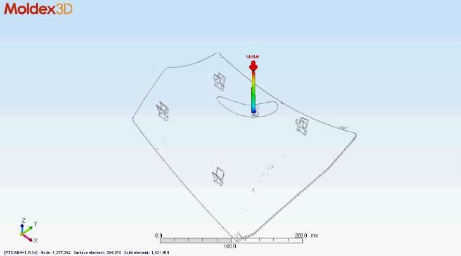
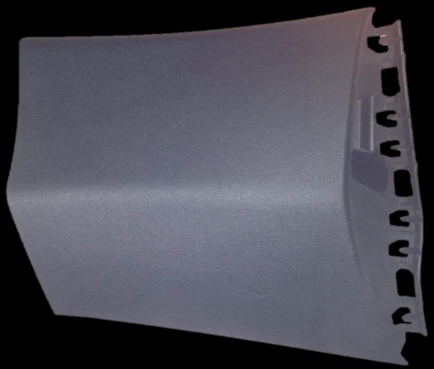
49 RICH CASE STUDY PVC VENT COVER

50 Vent Cover RICH Moldex 3d Analysis Report 14/10/14
51 Background RICH Moldex 3d Analysis Report Following successful validation trials using an existing production mould, it was decided that the existing mould design be modified to include additional channels and background circuits to make the mould more compatible for RICH. This would then reduce the overall cycle time. At the moment the existing part has a 4.5mm wall thickness with 3.3mm rib sections attached on the B side. Evidence from the trials indicates that RICH greatly improves plastic packing using slow injection speeds and extended packing times. Therefore we have analysed a part with a general wall thickness of 3mm. Note: It is not possible to reduce the rib thickness on the B side to improve the rib to wall thickness ratio. Therefore the customer provided CAD data for the modified mould, new channel circuit and the part with 3mm and 4.5mm respectively. This is to analyse results with and without RICH and with and without reduced wall thickness.
52 Objectives Moldex 3d Analysis Report Based upon latest 3d Mould model (step format) create mould model within the Moldex 3D environment including mould plates and channel circuits received from the customer Creation and Preparation of model mesh. Model RICH channels into the A side of the mold Simulation of heating and cooling the internal channel circuit with steam in order to predict:- a) Heating Uniformity b) Equilibrium effect of heat cycling the mould over a series of cycles. Plastic filling and packing analysis Based upon results optimisation of the mould design in order to achieve:- a) Fastest Heating Speed b) Fastest Cooling speed c) Shortest Overall cycle time. 1. Analysis of the component with the modified internal channel design and 4.5mm wall thickness. 2. Analysis of the component with the modified internal channel design and 3mm wall thickness


53 3d Part Models 4.5mm Wall Thickness 3mm Wall Thickness

54 3d Mold Internal Channel Model Background Circuit cavity side set at 50 C RICH Circuit cavity side Background Circuit core side set at 50 C

55 Temperature Sensor Positions
56 Process Conditions Used For The Analysis Material PVC Initial mold temperature first cycle = 50 C Melt temperature = 180 C Plastic injection time = 15 seconds Plastic packing time = 15 seconds Heating Time = 10 seconds Cooling time = 30 seconds Tool open time = 3 seconds Steam temperature = 180 C Water temperature = 15 C Target Mold Surface Temperature Heated = 85 C Target Mold Surface Temperature Cooled = 50 C

57 Process Conditions Used For The Analysis
58 RICH Heating and Cooling Profile Plastic Filling Time 15 Sec Plastic Packing Time 15 Sec Target Temperature 85 C Cavity Side Sensor 1Cavity Side Sensor 2 Core Side Sensor 1 Core Side Sensor 2 Core Side Sensor 3 Mould Open Time 3 Sec Heating 10 Sec Cooling Time 30 Sec
59 RICH Heating and Cooling Profile This sectioned view shows the steel and plastic surface temperature 1 second into plastic injection. This sectioned view shows the temperature midway through plastic packing.

60 RICH Heating and Cooling Profile This sectioned view shows the temperature close to the end of cooling This sectioned view shows the temperature half way through the heating cycle when the mould is opened.
61 Plastic Filling Pattern without RICH This the filling pattern for the 3mm thickness without RICH.

62 Plastic Filling Pattern with RICH This the filling pattern for the 3mm thickness with RICH
63 Plastic Filling Pattern with RICH Comparison 3mm Wall Section Without RICH the last points to fill are the corners of the general wall section With RICH the last points to fill change to the ends of the rib sections on the B side of the part. This is because the hot cavity surface encourages the plastic to fill the general wall section before the rib sections that are in the core side of the mould
64 Plastic Filling and Packing Pressure with RICH This graph shows the pressure at the tip of the sprue during the cycle with 4.5mm wall thickness. This graph shows the same pressure with wall 3mm thickness. As expected the pressure to fill the 3mm wall thickness is higher than the result for the 4.5mm wall thickness.

65 Part Temperature with RICH Temperature at the end of cooling 4.5mm Wall Thickness Temperature at the end of cooling 3mm Wall Thickness


66 Part Temperature with RICH This shows the temperature distribution on the surface of the 3mm thick component with different packing times. The plots show that changing packing has little effect on the plastic temperature at the end of cooling
67 Sink Mark Prediction after RICH 3mm thick with shorter and longer pack but the same cycle time. The left hand image shows the plastic that is still molten at the end of 15secs pack. The right hand image shows the same plot with the extended 25 seconds pack time.

68 Sink Mark Prediction after RICH 4.5mm wall thickness compared to 3mm wall thickness. This plot shows the sink mark prediction with the 4.5mm wall thickness and the original 15 Sec pack time. This plot shows the sink for the 3mm wall thickness with the original 15 sec packing. The sink position and distribution is similar but the sink depth increases from to 0.08mm

69 Sink Mark Prediction after RICH 3mm wall thickness with 25 second packing time This plot shows the sink for the 3mm wall thickness with the original 15 sec packing. This plot shows the sink for the same 3mm wall thickness but with extended packing time 25 Seconds The extended pack reduces the predicted sink from 0.08 to 0.05mm

70 Warp Prediction with RICH This plot shows the warp for the 3mm wall thickness with the original 15 sec packing and the part is predicted to warp 1.7mm This plot shows the warp for the 3mm wall thickness with extended packing time. The predicted warp is reduced from 1.7mm to 0.7mm
71 Summary and comment Conclusion Cycle time achieved at the initial trial was 115 seconds. By modifying the mould to include conformal and background circuits we believe this could be reduced to between 75 and 85 seconds based upon the analysis results. The analysis predicts that we will see an increase in sink mark depth with the reduced 3mm wall thickness, this will be improved to an acceptable level by extending the packing time. This is feasible because RICH enables extended packing times at slower injection speeds due to the higher mould temperature that is above the Tg (glass transition) temperature of the material. We therefore believe that this part can be produced with a 3mm wall thickness at a cycle time of between 75 to 85 seconds subject to the mold being modified as the CAD data provided. System requirement RICH4 with RO water purifier.
72 RAPID ISOLATION COOLING & HEATING RICH MOULD DESIGN CONFORMAL CHANNEL DESIGN RICH + ISO TECHNOLOGY SYNERGY


73 Conformal flow channel Conformal cooling channel

74 Definition Application Test Advantage What is ISO Technology? ISO technology enables TRUE 3D geometric freedom of cooling channel design. With the bonding and varied insert core, ISO technology is able to overcome the limitations of straight line cooling channel design using a typical gun drill machine. Idealized cooling channel design using ISO technology maximizes cooling efficiency by minimizing dead spots in cooling channels and achieving optimized plastic flow in hot runner systems. * ISO is an AutoCAD terms for a View mode inclining X, Y, Z axes at 45º respectively. It also stands for YUDO s technical vision that views objects in three-dimensions to optimize TRUE 3D cooling channel design / Configure ideal fluidized layer considering shear rate / Eliminates hot spot / Uniform cooling of whole product / Shorten cooling & cycle time
 / Secure Hot Runner Balance / Realize Edge-less Channel / Eliminate Dead Spots inside")
 Effective Mold Temperature Control Mold (Split Type Core & Gate Bush) / Optimized Cooling Channel design / Shorten")
75 Definition Application Test Advantage What is ISO Technology? Channel Design & Processing Optimization Hot Runner (2-pcs Manifold) / Secure Hot Runner Balance / Realize Edge-less Channel / Eliminate Dead Spots inside Resin Flow Channels / Control the Channel Surface Roughness and Illumination / Implement Smooth and efficient color changes / Decrease Resin Flow Shear Stresses(Sensitive Material, LGF etc) Effective Mold Temperature Control Mold (Split Type Core & Gate Bush) / Optimized Cooling Channel design / Shorten Cooling & Cycle Time / Reduce Deformation and Shrinkage / Minimize Flow marks when used with RICH


76 Definition Application Test Advantage 4-1. Case Study for Centre Console Tradition cooling channel design In a typical tank cooling design, circulation of the coolant is difficult to approach as the existing flow sections result in a Hot spot. This results in extended cooling times. Possible Hot spot point

77 Definition Application Test Advantage 4-1. Case Study for Console CAE Analysis Due to non optimal coolant circulation deep in the core, a Hot Spot occurs as predicted Hot spot


78 Definition Application Test Advantage 4-1. Case Study for Console 3D Cooling Structure with the ISO Tech Machining cooling channels of core -> Bonding core plates -> Finishing core machining ISO Technology enables cooling channels to access previously inaccessible areas of the core, to eliminate hot spots and shorten cooling times. Core plate 1 Core plate 2 Core plate 3 Core plate 4 <3-leveled cooling line design> < Core Split Structure & Bonding >


79 Definition Application Test Advantage 4-1. Case Study for Console Core CAE Analysis using ISO Tech Cooling efficiency is significantly improved in the deep core eliminating the hot spot and reducing cycle time


80 Definition Application Test Advantage 4-1. Case Study for Console Comparison of Conventional and ISO Cooling Channels Design Temperature difference between conventional cooling channels design and ISO cooling channel design after 15 seconds of the cooling cycle Traditional Design ISO Technology Hot spot Excellent Cooling effect
81 BENEFITS OF RICH + ISO TECHNOLOGY As THE Global market leader in Hot Runner Technology YUDO is IDEALLY placed to influence customers choice of mold design and process selection PRIOR to commencement of tooling. RICH technology offers customers the ability to dramatically improve surface finishes, light weight parts and reduce warpage / distortion and sinkage. Using ISO technology YUDO can now offer optimzed true 3D Conformal Cooling Channel design for medium to large tools. Note: Currently YUDO s competitors for RICH technology can only offer Conformal Cooling for small inserts.


82 RICH ELECTRONIC APPLICATIONS


83 RICH AUTOMOTIVE APPLICATIONS


84 RICH WHITE GOODS APPLICATIONS FRONT LOADING WASHING MACHINE PANEL Before After
85 RICH STATISTICS ATTRIBUTE RICH STEAM HEATING MAX TOOL SURFACE TEMP C 245 HEATING SPEED K / SEC 8-10 MAX PART SIZE in mm SEPARATE CORE & CAVITY HEATING PART GEOMETRY UNLIMITED YES COMPLEX 3D INDICATIVE CYCLE TIME INCREASE* % INDICATIVE ENERGY CONSUMPTION kw * COMPARED TO CONVENTIONAL INJECTION MOULING AND WITHOUT WALL SECTION REDUCTION
86 RICH AUTOMOTIVE MARKET INTEREST AUTOMOTIVE OEM S FORD UK AUDI PSA HYUNDAI MERCEDES BENZ JAGUAR LAND ROVER AUTOMOTIVE TIER 1 SUPPLIERS MAGNA AUTOMOTIVE EXTERIOR AND INTERIOR MECAPLAST INTIER AUTOMOTIVE INTERIORS PLASTIC OMNIUM AUTO EXTERIORS CIE AUTOMOTIVE
87 RICH AUTOMOTIVE MARKET INTEREST EXTERIOR APPLICATIONS LIGHT BEZELS (ABS / PC) HEAD LAMP REFLECTORS (ABS /PC or ABS / PMMA) DOOR HANDLES (GF PA) VERTICLE BODY PANELS (LGF PP) INTERIOR APPLICATIONS CENTRE CONSULE GEAR SHIFT BEZEL (ABS / PC) AUDIO BEZELS (ABS / PC) A,B, C PILLARS (ABS / PC) UNDER BONNET ENGINE COVERS (GF PA / GF PP)
88 RAPID ISOLATION COOLING & HEATING - RICH A PANACEA FOR INJECTION MOLDED PARTS High gloss surface finish..rich Weld line / flow line visibility....rich Fiber visibility on surface..rich Silver streaks and splay marks RICH Replication of surface micro features.rich Warp age and distortion RICH Sink marks..rich Longer flow paths with thinner wall sections.rich Light weighting...rich Cycle time reductions RICH
89 WHY CHOOSE YUDO SUNS? ONE OF THE ORIGINAL DEVELOPERS OF THE TECHNOLOGY (2006) HIGH PRESSURE (35 BARG) INTEGRATED ELECTRIC BOILER SYSTEM WORLD CLASS DESIGN ENGINEERING SUPPORT POSSIBILITY TO COMBINE TECHNOLOGIES (RICH + ISO) (RICH + MUCELL) (RICH + GAM)


90 OVER 480 SYSTEMS RUNNING WORLDWIDE