NAME 345 Welding Technology Lecture 12 Welding Defects & Discontinuities
|
|
|
- Dwight Armstrong
- 5 years ago
- Views:
Transcription

1 NAME 345 Welding Technology Lecture 12 Welding Defects & Discontinuities Md. Habibur Rahman Lecturer Department of Naval Architecture & Marine Engineering Bangladesh University of Engineering & Technology Dhaka-1000, Bangladesh
2 Defects A flaw or flaws that by nature or accumulated effect render (cause) a part or product unable to meet minimum applicable acceptance standards or specifications. The term designates rejectability. Discontinuities An interruption of the typical structure of a material, such as a lack of homogeneity in its mechanical, metallurgical, or physical characteristics. A discontinuity is not necessarily a defect. 2
3 Discontinuity Classifications Welding Discontinuity Design Related Weld Process Related Metallurgical 3
4 Welding Joint Discontinuities Misalignment (hi-lo) Undercut Underfill Concavity or Convexity Excessive reinforcement Improper reinforcement Overlap Burn-through Incomplete or Insufficient Penetration Incomplete Fusion Surface irregularity Overlap Arc Strikes Inclusions Slag Wagontracks Tungsten Spatter Arc Craters Cracks Longitudinal Transverse Crater Throat Toe Root Underbead and Heat-affected zone Hot Cold or delayed Base Metal Discontinuities Lamellar tearing Laminations and Delaminations Laps and Seams Porosity Uniformly Scattered Cluster Linear Piping Heat-affected zone microstructure alteration Base Plate laminations Size or dimensions 4
5 Welding Defects Essentially a discontinuity or flaw is called a defect if it exceeds the acceptance limits established by engineering based on Fitness for Service criteria. Welding defects include the following: Porosity Trapped slag Lack of fusion Lack of penetration or excess penetration Undercut Hot cracking Hydrogen induced HAZ cracking Lamellar tearing Any of these defects are potentially disastrous as they can all give rise to high stress intensities which may result in sudden unexpected failure below the design load or in the case of cyclic loading, failure after fewer load cycles than predicted. 5
 Prevention: Workmanship. Transition angles not to exceed 2.5 to 1. Repair: Grinding.")
6 Misalignment (Hi-Lo) Definition: Amount a joint is out of alignment at the root. Cause: Carelessness. Also due to joining different thicknesses (transition thickness) Prevention: Workmanship. Transition angles not to exceed 2.5 to 1. Repair: Grinding. Careful on surface finish and direction of grind marks. Inside of Pipe /Tube difficult. Fig: Linear Misalignment 6
7 Undercut Definition: A groove cut at the toe of the weld and left unfilled. Cause: High amperage, electrode angle, long arc length, rust Prevention: Set machine on scrap metal. Clean metal before welding Repair: Weld with smaller electrode, sometimes must be low hydrogen with preheat. Sometimes must gouge first Undercut typically has an allowable limit. Different codes and standards vary greatly in the allowable amount Plate - the lesser of 1/32 or 5% (typ.) 7

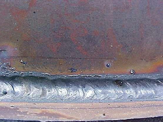
8 Undercut (Contd.) Fig: Undercut 8


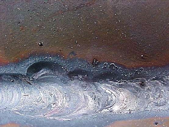
9 Insufficient Fill Definition: The weld surface is below the adjacent surfaces of the base metal Cause: Improper welding techniques Prevention: Apply proper welding techniques for the weld type and position Repair: Simply weld to fill. May require preparation by grinding 9
10 Concave and Convex Weld Profiles Concave: The concave defect cause the weld to be weak across the throat of the weld (Middle). Cause: The cause of this are: Travel speed is to quick Amps are to high Poor electrode Manipulation Convex: The convex defect cause the weld to become weak at the toes of the weld (outer edges). Cause: The cause of this are: Travel speed being to slow Amps to low Poor electrode manipulation. 10
11 Excessive Concavity or Convexity Definition: Concavity or convexity of a fillet weld which exceeds the specified allowable limits Cause: Amperage and travel speed Prevention: Observe proper parameters and techniques. Repair: Grind off or weld on. Must blend smoothly into the base metal. 11
12 Excessive Concavity or Convexity (Contd.) Concavity 12


13 Excessive Concavity or Convexity (Contd.) Fig: Root Concavity Fig: Excessive Concavity 13
14 Excessive Concavity or Convexity (Contd.) Convexity 14

15 Excessive Concavity or Convexity (Contd.) Fig: Excessive Convexity 14
16 Reinforcement The amount of a groove weld which extends beyond the surface of the plate Reinforcement Excessive Reinforcement Insufficient Reinforcement Improper Weld Contour Face Reinforcement Root Reinforcement 16
 or flush to 1/8 (plate or structural")

17 Excessive Reinforcement Definition: Specifically defined by the standard. Typically, Reinforcement should be flush to 1/16 (pipe) or flush to 1/8 (plate or structural shapes). Cause: Travel speed too slow, amperage too low Prevention: Set amperage and travel speed on scrap plate. Repair: Remove excessive reinforcement and feather the weld toes to a smooth transition to the base plate. 17
18 Insufficient Reinforcement Definition: Specifically defined by the standard. Typically, Underfill may be up to 5% of metal thickness not to exceed 1/32 as long as the thickness is made up in the opposite reinforcement Cause: On root reinforcement - Too little filler metal will cause thinning of the filler metal. In OH position, too hot or too wide will cause drooping of the open root puddle Prevention: Use proper welding technique. Use backing or consumable inserts. Use back weld or backing Repair: Possibly simply increase the face reinforcement. If back welding is not possible, must remove and reweld. 18
19 Improper Weld Contour Definition: When the weld exhibits less than a 135 transition angle at the weld toe. Cause: Poor welding technique Prevention: Use proper techniques. A weave or whip motion can often eliminate the problem. Repair: The weld face must be feathered into the base plate


20 Overlap Welding Defects & Discontinuities Definition: When the face of the weld extends beyond the toe of the weld. Cause: Improper welding technique. Typically, electrode angles and travel speed Prevention: Overlap is a contour problem. Proper welding technique will prevent this problem. Repair: Overlap must be removed to blend smoothly into the base metal. Be careful of deep grind marks that run transverse to the load. Also be careful of fusion discontinuities hidden by grinding. Use NDT to be sure Overlap is measured with a square edge such as a 6 rule. No amount of overlap is typically allowed. 20

21 Burn-through Definition: When an undesirable open hole has been completely melted through the base metal. The hole may or may not be left open Cause: Excessive heat input Prevention: Reduce heat input by increasing travel speed, use of a heat sink, or by reducing welding parameters. Repair: Will be defined by standards. Filling may suffice. Otherwise, removal and rewelding may be required. Some standards may require special filler metal 21
 b) Some of the causes are:- a) Excessively thick root gap.")
22 Incomplete fusion and Penetration Incomplete root fusion is when the weld fails to fuse one side of the joint in the root. Incomplete root penetration occurs when both sides of the joint are unfused. a) b) Some of the causes are:- a) Excessively thick root gap. b)too small a root gap c) Misaligned welds d)power input to low e) Arc (heat) input to low These defects can be reduced in MMA welding by using the correct welding parameters and electrode size, This will give the correct arc energy input c) d) e) 22

.")
23 Incomplete or Insufficient Penetration Definition: When the weld metal does not extend to the required depth into the joint root Cause: Low amperage, low preheat, tight root opening, fast travel speed, short arc length Prevention: Correct the contributing factor(s). Repair: Back gouge and back weld or remove and reweld. 23


24 Incomplete Fusion Definition: Where weld metal does not form a cohesive bond with the base metal Cause: Low amperage, steep electrode angles, fast travel speed, short arc gap, lack of preheat, electrode too small, unclean base metal Prevention: Eliminate the potential causes. Repair: Remove and reweld, being careful to completely remove the defective area. This is sometimes extremely difficult to find. 24


25 Arc Strike Definition: A localized coalescence outside the weld zone Cause: Carelessness Prevention: In difficult areas, adjacent areas can be protected using fire blankets. Repair: Where applicable, arc strikes must be sanded smooth and tested for cracks. If found, they must be remove and repaired using a qualified repair procedure and inspected as any other weld. 25
26 Inclusions Inclusions Slag Inclusions Wagontracks Tungsten Inclusions 26


27 Slag Inclusion Definition: Slag entrapped within the weld Cause: Low amperage, improper technique, trying to weld in an area that is too tight, slow travel in vertical down Prevention: Increase amperage or preheat, grind out tight areas to gain access to bottom of joint Repair: Remove by grinding, reweld. 27

28 Wagon Tracks Definition: Slang term for a groove left at the toe of a root pass which becomes filled with slag and is trapped in the weld. Cause: The contour of the root pass is too high, or the weld toe is not bonded to the base metal Prevention: Use proper technique to deposit the weld root Repair: Carefully grind the root pass face flat. be careful not to gouge other areas on the weldment. 28

29 Whiskers Welding Defects & Discontinuities Definition: Whiskers are short lengths of electrode wire sticking through the weld on the root side of the joint Cause: They are caused by pushing the electrode wire past the leading edge of the weld pool Prevention: Reducing the wire-feed speed and the speed of travel, increasing the stick-out distance and weaving the gun i. Unsightly ii. Inhibits material flow in piping iii. Are inclusions iv. Can break off in pipes and damage equipment downline 29


30 Spatter Welding Defects & Discontinuities Definition: Small particles of weld metal expelled from the welding operation which adhere to the base metal surface Cause: Long arc length, severe electrode angles, high amperages Prevention: Correct the cause, base metal can be protected with coverings or hi-temp paints. Repair: Remove by grinding or sanding. Sometimes must be tested as if it were a weld. 30
31 Arc Craters Definition: A depression left at the termination of the weld where the weld pool is left unfilled Cause: Improper weld termination techniques Repair: If no cracks exist, simply fill in the crater. Generally welding from beyond the crater back into the crater. 31

32 Cracks Welding Defects & Discontinuities Definition: A crack is produced by a fracture which can arise from the stresses generated on cooling or acting on the structure. It is the most serious type of imperfection found in a weld and must be removed. Cracks not only reduce the strength of the weld through the reduction in the cross section thickness but also can readily propagate through stress concentration at the tip, especially under impact loading or during service at low temperature. There are different types of cracks: i. Longitudinal ii. iii. iv. Transverse Crater Throat v. Toe vi. Root vii. Underbead and Heat-affected zone (HAZ) viii. Hot ix. Cold or delayed 32
33 Longitudinal Crack Definition: A crack running in the direction of the weld axis. May be found in the weld or base metal Cause: Preheat or fast cooling problem. Also caused by shrinkage stresses in high constraint areas Prevention: Weld toward areas of less constraint. Also preheat to even out the cooling rates. Repair: Remove and reweld. 33
34 Transverse Crack Definition: A crack running into or inside a weld, transverse to the weld axis direction Cause: Weld metal hardness problem 34
35 Crater Crack Definition: A crack, generally in the shape of an X which is found in a crater. Crater cracks are hot cracks Cause: The center of the weld pool becomes solid before the outside of the weld pool, pulling the center apart during cooling Prevention: Use crater fill, fill the crater at weld termination and/or preheat to even out the cooling of the puddle. 35
36 Throat Crack Definition: A longitudinal crack located in the weld throat area Cause: Transverse Stresses, probably from shrinkage. Indicates inadequate filler metal selection or welding procedure. May be due to crater crack propagation Prevention: Correct initial cause. Increasing preheat may prevent it. be sure not to leave a crater. Use a more ductile filler material. Repair: Remove and reweld using appropriate procedure. Be sure to correct initial problem first. 36
37 Root Crack Definition: A crack in the weld at the weld root Cause: Transverse shrinkage stresses. Same as a throat crack Prevention: Same as a throat crack. 37
38 Toe Crack Definition: A crack in the base metal beginning at the toe of the weld Cause: Transverse shrinkage stresses. Indicates a HAZ brittleness problem Prevention: Increase preheat if possible, or use a more ductile filler material. 38
39 Underbead Crack Definition: A crack in the unmelted parent metal of the HAZ Cause: Hydrogen embrittlement Prevention: Use Lo/Hi electrodes and/or preheat. Repair: (only found using NDT). Remove and reweld. 39
40 Hot Crack Definition: A crack in the weld that occurs during solidification Cause: Micro stresses from weld metal shrinkage pulling apart weld metal as it cools from liquid to solid temp Prevention: Preheat or use a low tensil filler material. 40

41 Cold Crack Definition: A crack that occurs after the metal has completely solidified Cause: Shrinkage, Highly restrained welds, Discontinuities Prevention: Preheat, weld toward areas of less constraint, use a more ductile weld metal. Repair: Remove and reweld, correct problem first, preheat may be necessary. 41
42 Base Metal Discontinuities i. Lamellar tearing ii. iii. Laminations and Delaminations Laps and Seams 42
43 Laminations Base Metal Discontinuity May require repair prior to welding Formed during the milling process Lamination effects can be reduced by joint design: 43
44 Lamellar Tearing IT is a dangerous planar defect occurring when certain plate materials presenting laminations are welded to a perpendicular element. Tearing occurs in the base metal plate adjacent to welds due to high shrinkage stresses in the thickness direction, introduced by weld metal shrinkage in highly restrained joints. Tearing takes place along laminations. These internal cracks usually run parallel to the weld. 44
45 Defects in GTAW i. Cracks ii. Lack Of Fusion iii. Porosity iv. Undercut v. Lack Of Penetration vi. Excess Penetration vii. Overlap viii. Suck Back ix. Under Flush x. Burn Through xi. Tungsten Inclusion 45
46 Defects in GTAW (Contd.) Crack Cause i. Wrong Consumable ii. iii. iv. Wrong Procedure Improper Preheat Inadequate Thickness In Root Pass Remedy i. Use Right Filler Wire ii. iii. iv. Qualify Procedure Preheat Uniformly Add More Filler Wire in root Pass crack 46
47 Defects in GTAW (Contd.) Lack of Fusion Cause i. Inadequate Current ii. Wrong Torch angle iii. Improper bead placement Remedy i. Use Right Current ii. Train /Qualify welder iii. Train/Qualify Welder Lack Of Fusion 47
48 Defects in GTAW (Contd.) Porosity Cause i. Impure Argon Gas ii. Argon Leak Within Torch iii. Defective Filler Wire iv. Wet surface of BM v. Rusted / Pitted Filler wire vi. Improper Flow Of Argon Remedy i. Replace Argon Cylinder ii. Replace Leaking Torch iii. Replace Filler Wire iv. Clean & Warm BM v. Clean Filler Wire vi. Provide Gas lens Porosity.. 48
49 Defects in GTAW (Contd.) Undercut Cause i. Excess Current ii. Excess Voltage iii. Improper Torch angle Remedy i. Reduce the Current ii. iii. Reduce Arc length Train & Qualify the Welder Under cut 49
50 Defects in GTAW (Contd.) Lack Of Penetration Cause i. Excess Root Face ii. iii. iv. Inadequate Root opening Over size Filler Wire Wrong Direction of Arc v. Improper bead placement vi. Improper weaving technique Remedy i. Reduce Root Face ii. Increase Root Opening iii. Reduce Filler Wire size iv. Train / Qualify Welder v. Train / Qualify Welder vi. Train & Qualify Welder LOP 50
51 Defects in GTAW (Contd.) Excess Penetration Cause i. Excess root opening ii. Excess Current iii. Inadequate root face iv. Excess Weaving v. Wrong Direction Of Arc Remedy i. Reduce root gap ii. Reduce Current iii. Increase Root face iv. Train Welder v. Train Welder Excess Penetration 51
52 Defects in GTAW (Contd.) Overlap Cause i. Wrong Direction Of Arc ii. Inadequate Current iii. Excess Filler Wire Remedy i. Train & Qualify Welder ii. Increase Current iii. Reduce Filler Metal Overlap 52
53 Defects in GTAW (Contd.) Suck Back Cause i. Excess weaving in root ii. Excess Current iii. Inadequate root face iv. Wrong Electrode angle Remedy i. Reduce weaving ii. Reduce Current iii. Increase root face iv. Train / Qualify Welder Suck Back 53
54 Defects in GTAW (Contd.) Under flush Cause i. Inadequate weld beads in final layer ii. Inadequate understanding on weld reinforcement iii. Wrong selection of filler wire size Remedy i. Weld some more beads in final layer ii. iii. Train / Qualify welder Train / Qualify Welder Under flush 54
55 Defects in GTAW (Contd.) Burn Through Cause i. Excess Current ii. Excess Root opening iii. Inadequate Root face iv. Improper weaving Remedy i. Reduce the Current ii. Reduce root opening iii. Increase root face iv. Train / Qualify Welder Burn Through 55
56 Defects in GTAW (Contd.) Tungsten Inclusion Cause i. Ineffective HF ii. Improper Starting of Arc iii. Tungsten Tip Comes in Contact With Weld Remedy i. Rectify HF Unit ii. iii. Never Touch Weld With Tungsten Rod Train / Qualify welder Tungsten Inclusion 56
57 Defects in GMAW i. Porosity ii. Spatters iii. Lack of Fusion iv. Undercut v. Overlap vi. Slag vii. Crack viii. Lack of Penetration ix. Burn Through x. Convex Bead xi. Unstable Arc 57
58 Defects in GTAW (Contd.) Porosity Cause i. Less Mn & Si In Wire ii. Rusted / Unclean BM / Groove iii. iv. Rusted wire Inadequate Shielding Gas Remedy i. Use High Mn & Si Wire ii. iii. Clean & warm the BM Replace the Wire iv. Check & Correct Flow Rate Porosity.. 58
59 Defects in GTAW (Contd.) Spatters Cause i. Low Voltage ii. Inadequate Inductance iii. Rusted BM surface iv. Rusted Core wire v. Quality Of Gas Remedy i. Increase Voltage ii. Increase Inductance iii. Clean BM surface iv. Replace By Rust Free wire v. Change Over To Ar + CO 2 Spatters 59
60 Defects in GTAW (Contd.) Lack Of Fusion Cause i. Inadequate Current ii. Inadequate Voltage iii. Wrong Polarity iv. Slow Travel Speed v. Excessive Oxide On Joint Remedy i. Use Right Current ii. Use Right Voltage iii. Connect Electrode +ve iv. Increase Travel speed v. Clean Weld Joint Lack Of Fusion 60
61 Defects in GTAW (Contd.) Undercut Cause i. Excess Voltage ii. Excess Current iii. Improper Torch angle iv. Excess Travel Speed Remedy i. Reduce Voltage ii. Reduce Current iii. Train & Qualify the Welder iv. Reduce Travel Speed Undercut 61
62 Defects in GTAW (Contd.) Overlap Cause i. Too Long Stick Out ii. Inadequate Voltage Remedy i. Reduce Stick Out ii. Increase the Voltage Overlap 62
63 Defects in GTAW (Contd.) Slag Cause i. Inadequate Cleaning ii. Inadequate Current iii. Wrong Torch angle iv. Improper bead placement Remedy i. Clean each bead ii. Use Right Current iii. Train / Qualify welder iv. Train / Qualify Welder Slag 63
64 Defects in GTAW (Contd.) Crack Cause i. Incorrect Wire Chemistry ii. Too Small Weld Bead iii. Improper Preheat iv. Excessive Restrain Remedy i. Use Right Wire ii. Increase wire Feed iii. Preheat Uniformly iv. Post heating or ISR crack 64
65 Defects in GTAW (Contd.) Lack of Penetration Cause i. Too Narrow Groove Angle ii. Inadequate Root opening iii. Too Low Welding current iv. Wrong Torch angle v. Puddle roll in front of arc vi. Long Stick Out Remedy i. Widen The Groove ii. Increase Root Opening iii. Increase Current iv. Train / Qualify Welder v. Correct Torch Angle vi. Reduce Stick Out LOP 65
66 Defects in GTAW (Contd.) Burn Through Cause i. Excess Current ii. Excess Root opening iii. Inadequate Root face iv. Too Low Travel Speed v. Quality Of Gas Remedy i. Reduce the Current ii. Reduce root opening iii. Increase root face iv. Increase Speed v. Use Ar + CO 2 Burn trough *Applicable to root pass 66
67 Defects in GTAW (Contd.) Convex Bead Finish Cause i. Low Current ii. Low Voltage iii. Low Travel Speed iv. Low Inductance v. Too Narrow Groove Remedy i. Increase Current ii. Increase Voltage iii. Increase Travel Speed iv. Increase Inductance v. Increase Groove Width Uneven bead finish 67
68 Defects in GTAW (Contd.) Unstable arc Cause i. Improper Wire Feed ii. Improper Gas Flow iii. Twisted Torch Conduit Remedy i. Check Wire Feeder ii. Check Flow Meter iii. Straighten Torch Cab 68
69 Summery