Modeling: (i) thermal spray rapid solidification (ii) partially molten particle impact
|
|
|
- Silvester Payne
- 5 years ago
- Views:
Transcription
1 Modeling: (i) thermal spray rapid solidification (ii) partially molten particle impact Markus Bussmann Mechanical & Industrial Engineering Centre for Advanced Coating Technologies (CACT) University of Toronto
2 (i) thermal spray rapid solidification Bob (Haibo) Liu, PhD Markus Bussmann, Javad Mostaghimi
 spraying distance: 50 mm")

3 Thermal Spray Coating Thermal spraying YSZ (yttria stabilized zirconia) spraying distance: 50 mm velocity: 125 ± 20 m/s particle diameter: µm splat thickness: 2 µm cooling rate: ~ 10 6 K/s 100 µm 3/22

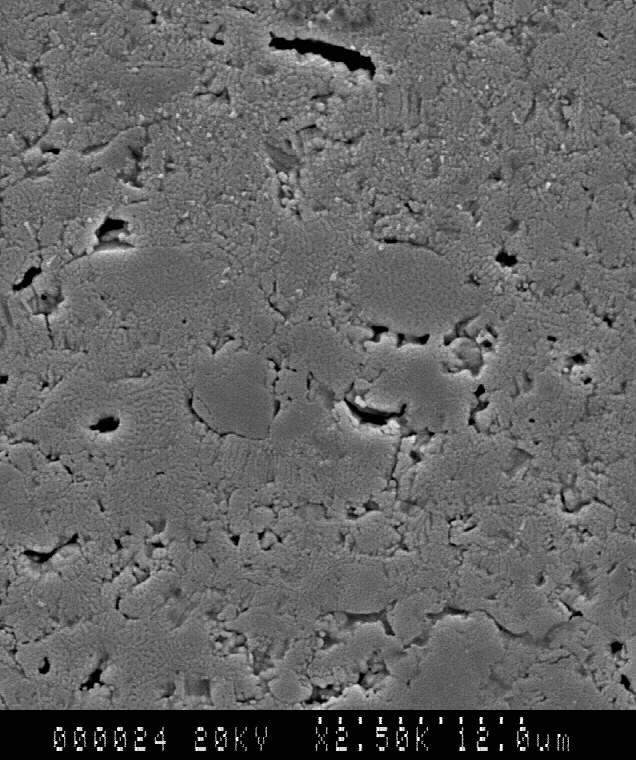
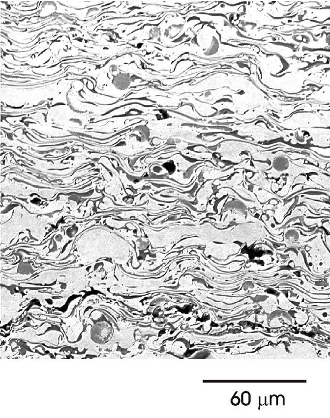
4 SEM of a TBC cross-section N.P. Padture et al., Science 296, 280, /22
5 YSZ phase diagram 5/22


6 CACT equilibrium model assumes a pure material solidifying at good prediction of overall splat shape/ morphology no microstructure prediction T m 6/22
7 Rapid solidification non equilibrium or meta/unstable high interface velocity undercooling (T i <T m ) non uniform distribution of solute different solid phases 7/22
8 Objective develop a model to predict: microstructure, including: grain size, morphology, transformation, during rapid solidification concentration distribution accurate solidification velocity 8/22

9 YSZ T. Chraska et al, Thin Solid Films 40, 397, /22

10 Alloy 625 Ni-based alloy 10/22

11 Alloy /22
12 1D Interface Tracking Method G. X. Wang et al, Mater. Manuf. Process 19, 259, /22
13 T & C eqns + ICs + BCs T j t =α j 2 T j T(x,0) =T o T(0,t) x T(b,t) x = h[ T(0,t) T ] = 0 C L t = D L 2 C L C(x,0) = C o C(0,t) x = C(b,t) x = 0 G. X. Wang et al, Mater. Manuf. Process 19, 259, /22
14 interface conditions energy conservation : T ρ L V i L = K S T s K L L x i x i mass conservation : ( C C L C S )V i = D L L x i from phase diagram : C S = k f C L undercooling : T i =T m + m C L V i /µ 14/22
15 parabolic model everything so far is traditional why? because the diffusion equations are based on: Fourier s Law: J = k T Fick s Law: J c = D C but these assume an infinite diffusive speed i.e. a sudden change in T or C is instantaneously felt everywhere in a domain 15/22
16 finite diffusive speed v d Liquid Solid non equilibrium diffusion: ν d = D /a 0 : diffusive speed ν d a 0 ν n : inter atomic spacing : solid/liquid interface velocity ν n leads to a relaxation time τ 2 D= D /ν d 16/22
17 v d vs v n? ν n = 0 global equilibrium: T=const, C=const ν n <<ν d local equilibrium: steady states ν n <ν d ν n ~ ν d diffusional local equilibrium: parabolic equations (non equilibrium partition coefficient k at the interface) diffusional non equilibrium: hyperbolic equations ν n >ν d C S = C L = C 0 (partitionless) S.L. Sobolev, Phys. Rev. E 55, 6845, /22
18 Cattaneo devised modified laws in 1948: Fourier s Law: τ J dt + J = k T Fick s Law: τ D J C t + J c = D C 18/22
19 hyperbolic model T t + τ 2 T t 2 =α 2 T C L t + τ D 2 C L t 2 = D 2 C L T(x,0) =T o T(0,t) x T(b,t) x = h[ T(0,t) T ] = 0 C(x,0) = C o C(0,t) x = C(b,t) x = 0 19/22
20 hyperbolic interface BCs energy conservation : mass conservation : (τ t +1)ρ L V i L = K T S T s K L L x i x i ( C L C S )V i + τ D t ((C C L C s )V i ) = D L L x i from phase diagram : C S = k f C L undercooling : T i =T m + m C L V i /µ 20/22
21

22 planar vs cellular interface morphology 22/22
23 two indications of grain size 1) if planar, then grain size is determined by the initial nucleation density, which is a function of initial undercooling (nucleation temperature) T. Chraska et al, Thin Solid Films 40, 397, /22
24 2) if cellular, the grain tips are curved; curvature can be determined via stability theory; and curvature determines grain size (KGT model) 24/22
25 Results solved the hyperbolic T and C equations using the same relaxation time solution method: MacCormack s predictorcorrector scheme pure Al temperature only YSZ 8 wt% yttria Alloy 625 Ni 21 wt% Cr alloy 25/22
26 Al temperature only 26/22
27 YSZ interface velocity 27/22
28 YSZ solid-side concentration 28/22
29 YSZ liquid side gradients 29/22
30 YSZ grain radius Upper limit Lower limit Grain morphology transformation 30/22
31 grain radius for Alloy /22
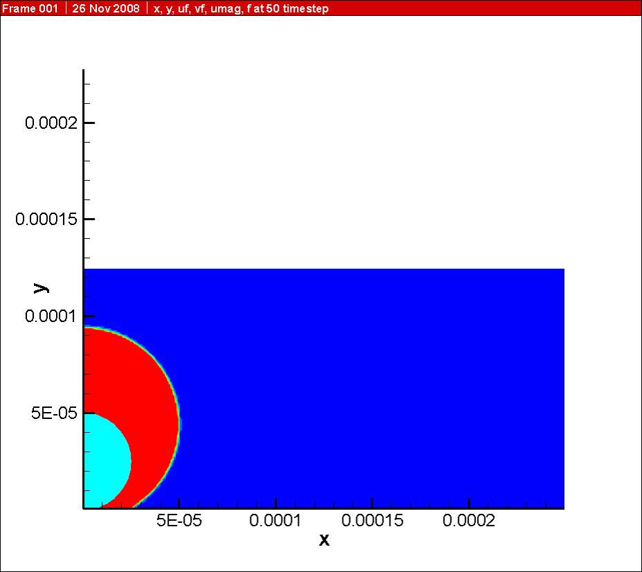
32 (ii) partially molten particle impact Tommy (Cheming) Wu, MASc Markus Bussmann, Javad Mostaghimi
33 Semi-Molten Droplets? Insufficient heating of oxidation sensitive materials (e.g. MCrAlY) Liquid Shell Solid Core Composite coatings (e.g. WC Co carbides in a cobalt matrix) Liquid Co Matrix WC WC WC WC WC WC WC WC WC WC WC 33/22

34 C.J. Li et al., Materials Science and Technology, 2004
35 YSZ cross-section 35/22
36 Ni cross-section 36/22
37 model 37/22
38 model 38/22

39 IB method of Uhlmann 39/22
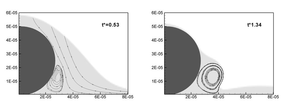
40 Validation axisymmetric flow past a solid sphere, at various Re 40/22

41
42 42/22
43 YSZ sims 43/22
44
45
46
47
48
49 Spread 100 µm, 100 m/s 49/22
50 Spread 50 µm, 100 m/s 50/22