Hail University College of Engineering Department of Mechanical Engineering. Metal-Forging Processes and Equipment. Ch 14
|
|
|
- Reynard Reeves
- 5 years ago
- Views:
Transcription
1 Hail University College of Engineering Department of Mechanical Engineering Metal-Forging Processes and Equipment Ch 14
2 Metal-Forging Forging is a basic process in which the work piece is shaped by compressive forces applied through various dies and tooling. Forging first was used to make jewelry, coins, and various implements by hammering metal with tools made of stone. Forged parts now include large rotors for turbines; gears; bolts and rivets; cutlery hand tools; numerous structural components for machinery, aircraft and railroads; and a variety of other transportation equipment. Unlike rolling operations described before that generally produce continuous plates, sheets, strips, or various structural cross sections, forging operations produce discrete parts. Because the metal flow in a die and the material's grain structure can be controlled, forged parts have good strength and toughness, and are very reliable for highly stressed and critical applications
 Landing-gear components for the C5A and C5B transport aircraft, made by forging.")
3 Metal-Forging Illustration of the steps involved in forging a knife. (b) Landing-gear components for the C5A and C5B transport aircraft, made by forging. (c) General view of a 445-MN (50,000-ton) hydraulic press.
 Casting by the processes (b) Machining from a blank, described in Part IV of this book, and (c) forging.")
4 Metal-Forging Schematic illustration of a part made by three different processes and showing grain flow. (a) Casting by the processes (b) Machining from a blank, described in Part IV of this book, and (c) forging. Each process has its own advantages and limitations regarding external and internal characteristics, material properties, dimensional accuracy, surface finish, and the economics of production.. Simple forging operations can be performed with a heavy hammer and an anvil, as has been done traditionally by blacksmiths. However, most forgings require a set of dies and such equipment as a press or a powered forging hammer.
5 Metal-Forging Forging may be carried out at room temperature (cold forging) or at elevated temperatures (warm or hot forging) depending on the homologous temperature; Cold forging requires higher forces (because of the higher strength of the work piece material), and the work piece material must possess sufficient ductility at room temperature to undergo the necessary deformation without cracking Forgings generally are subjected to.additional finishing operations, such as heat treating to modify properties and machining to obtain accurate final dimensions and a good surface finish. These finishing operations can be minimized by precision forging, which is an important example of net-shape or near-net-shape forming processes.
 to very large (up to 23 m, long shafts for ship propellers).")
6 Open-die Forging Open-die forging is the simplest forging operation Although most open-die forgings generally weigh 15 to 500 kg, forgings as heavy as 275 metric tons have been made. Part sizes may range from very small (the size of nails, pins, and bolts) to very large (up to 23 m, long shafts for ship propellers). General Characteristics of Forging Processes
 Solid cylindrical billet upset between two flat dies.")
7 Open-die Forging Open-die forging can be depicted by a solid workpiece placed between two flat dies and reduced in height by compressing it a process that is also called upsetting or flat die forging. The die surfaces also may have shallow cavities or incorporate features to produce relatively simple forgings. (a) Solid cylindrical billet upset between two flat dies. (b) Uniform deformation of the billet without friction. (c) Deformation with friction. Note barreling of the billet caused by friction forces at the billet die interfaces.

8 Open-die Forging In actual operations, however, there is friction, and the part develops a barrel shape -a deformation mode also known as Pancaking. Barreling is caused primarily by frictional forces that oppose the outward flow of the workpiece at the die interfaces and thus can be minimized by using an effective lubricant. Barreling also can develop in upsetting hot workpieces between cold dies. The material at or near the die surfaces cools rapidly, while the rest of the workpiece remains relatively hot. Consequently, the material at the top and bottom of the workpiece has higher resistance to deformation than the material at the center. As a result, the central portion of the workpiece expands laterally to a greater extent than do the ends. Barreling from thermal effects can be reduced or eliminated by using heated dies. Thermal barriers, such as glass cloth, at the die-workpiece interfaces also can be used for this purpose.

9 Cogging (also called drawing out) is basically an open-die forging operation in which the thickness of a bar is reduced by successive forging steps (bites) at specific intervals. Because the contact area between the die and the workpiece is small, a long section of a bar can be reduced in thickness without requiring large forces or heavy machinery. Blacksmiths perform such operations with a hammer and an anvil, using hot pieces of metal. (a) Schematic illustration of a cogging operation on a rectangular bar. Blacksmiths use this process to reduce the thickness of bars by hammering the part on an anvil. Reduction in thickness is accompanied by barreling, (b) Reducing the diameter of a bar by open-die forging; note the movements of the dies and the workpiece. (c) The thickness of a ring being reduced by open-die forging.
10 Forging Force The forging force, F, in an open-die forging operation on a solid cylindrical workpiece can be estimated from the formula where Y f is the flow stress of the material µ is the coefficient of friction between the workpiece and the die, and r and h are, respectively, the instantaneous radius and height of the workpiece.
11 Example: Calculation of forging force in upsetting A solid cylindrical slug made of 304 stainless steel is 150 mm in diameter and 100 mm high. It is reduced in height by 50% at room temperature by opendie forging with flat dies. Assuming that the coefficient of friction is 0.2 and the flow stress of this material is 1000 MPa, calculate the forging force at the end of the stroke.

12 Impression-die and Closed-die Forging In impression-die forging, the workpiece takes the shape of the die cavity while being forged between two shaped dies This process usually is carried out at elevated temperatures to lower the required forces and attain enhanced ductility in the workpiece. during deformation, some of the material flows outward and forms a flash. (a) through (c) Stages in impression-die forging of a solid round billet. Note the formation of flash, which is excess metal that is subsequently trimmed off. (d) Standard terminology for various features of a forging die.

13 Impression-die and Closed-die Forging Instead of being made as one piece, dies may be made of several pieces (segmented), including die inserts and particularly for complex shapes. The inserts can be replaced easily in the case of wear or failure in a particular section of the die and usually are made of stronger and harder materials. Die inserts used in forging an automotive axle housing.
14 Preforming operations typically are used to distribute the material properly into various regions of the blank using simple shaped dies of various comours. In fullering, material is distributed away from an area In edging, it is gathered into a localized area. (a) Stages in forging a connecting rod for an internal combustion engine. Note the amount of flash required to ensure proper filling of the die cavities. (b) Fullering and (c) edging operations to distribute the material properly when preshaping the blank for forging.

15 Impression-die Forging The part then is formed into the rough shape (say, a connecting rod) by a process called blocking, using blocker dies. The final operation is the finishing of the forging in impression dies that give the forging its final shape. The flash is removed later by a trimming operation Trimming flash from a forged part. Note that the thin material at the center is removed by punching.

16 Forging force. The forging force, F, required to carry out an impression-die forging operation can be estimated from the formula where k is a multiplying factor obtained from Table 14.2, Y f is the flow stress of the material at the forging temperature, and A is the projected area of the forging, including the flash.
17 Example: Calculation of forging force Calculate the forging force for the cylindrical workpiece made of 1020 steel that is 90 mm high and 125 mm in diameter and is reduced in height by 40%. Assuming that it is a complex forging and that the projected area of the flash is 30% greater than the projected area of the forged workpiece.

18 Forging force. impression-die forging operation In hot-forging operations, the actual

19 Closed-die Forging in true closed-die forging, flash does not form (hence the term (flashless forging), and the workpiece completely fills the die cavity the forging pressure is very high, and accurate control of the blank volume and proper die design are essential to producing a forging with the desired dimensional tolerances. Comparison of (a) closed-die forging with flash and (b) precision or flashless forging of a round billet. Regardless, the term closed-die forging is often applied to impression die forging with flash generation, whereas open-die forging generally applies to operations with simple dies and tooling and with large deformations.
20 Precision Forging In order to reduce the number of additional finishing operations required-hence the cost-the trend has been toward greater precision in forged products (net-shape forming). Typical precision-forged products are gears, connecting rods, and turbine blades. Precision forging requires (a) special and more complex dies, (b) precise control of the 'blank's volume and shape, and (e) accurate positioning of the blank in the die cavity. Also, because of the higher forces required to obtain fine details on the part, this process requires higher capacity equipment. Aluminum and magnesium alloys are particularly suitable for precision forging because of the relatively low forging loads and temperatures that they require; however, steels and titanium also can be precision forged.
21 Forging Practice and Product Quality A forging operation typically involves the following sequence of steps: 1.Prepare a slug, billet, or preform by processes such as shearing (cropping), sawing, or cutting off. If necess.:lry, clean surfaces by such means as shot blasting. 2. For hot forging, heat the workpiece in a suitable furnace and then, if necessary, descale it with a wire brush, water jet, steam, or by scraping. Some descaling also may occur during the initial stages of forging, when the scale (which is brittle) falls off during deformation. 3. For hot forging, preheat and lubricate the dies; for cold forging, lubricate the blank. 4. Forge the billet in appropriate dies and in the proper sequence. If necessary, remove any excess material (such as flash) by trimming, machining, or grinding. 5.Clean the forging, check its dimensions, and (if necessary) machine it to final dimensions and specified tolerances. 6. Perform additional operations, such as straightening and heat treating (for improved mechanical properties). Also, perform any finishing operations that may be required, such as machining and grinding. 7. Inspect the forging for any external and internal defects.
, the pressures required can be as high as five or six times the strength of the material.")
22 Various Forging Operations Several other operations related to the basic forging process are carried out in order to impart the desired shape and features to forged products. Coining In order to produce fine details (for example, the detail on newly minted coins), the pressures required can be as high as five or six times the strength of the material. (a) Schematic illustration of the coining process. The earliest coins were made by open-die forging and lacked precision and sharp details. (b) An example of a modern coining operation, showing the coins and tooling. Note the detail and superior surface finish that can be achieved in this process..

23 Heading Also called upset forging, heading is essentially an upsetting operation, usually performed on the end of a round rod or wire in order to increase the cross section. An important consideration in heading is the tendency for the bar to buckle if its unsupported length-todiameter ratio is too high. This ratio usually is limited to less than 3:1, (a) Heading operation to form heads on fasteners, such as nails and rivets. (b) Sequence of operations used to produce a typical bolt head by heading.

24 Piercing This is a process of indenting (but not breaking through) the surface of a workpiece with a punch in order to produce a cavity or an impression The deformation of the workpiece will depend on how much it is constrained from flowing freely as the punch descends. The piercing force depends on (a) the cross-sectional area and the tip geometry of the punch, (b) the strength of the material, and (c) the magnitude of friction at the sliding interfaces A pierced round billet showing grain-flow pattern.

25 CASE STUDY, Manufacture of a Stepped Pin by Heading and Piercing Operations a stepped pin made from SA E 1008 steel and used as a part of a roller assembly to adjust the position of a car seat. (a) The stepped pin used in Case Study (b) Illustration of the manufacturing steps used to produce the stepped pin.
26 Isothermal Forging Isothermal Forging. Also known as hot-die forging, this process heats the dies to the same temperature as that of the hot workpiece. Because the workpiece remains hot, its flow strength and high ductility are maintained during forging. Also, the forging load is low, and material flow within the die cavity is improved. Complex parts with good dimensional accuracy can be isothermally forged to near-net shape by one stroke in a hydraulic press. The dies for hot forging of high-temperature alloys usually are made of nickel or molybdenum alloys (because of their resistance to high temperature), but steel dies can be used for aluminum alloys. Isothermal forging is expensive and the production rate is low.
, a solid rod or tube is subjected to radial impact forces by a set of reciprocating dies of the machine The die")
27 Rotary Swaging Rotary Swaging. In this process (also known as radial forging, rotary forging, or simply swaging), a solid rod or tube is subjected to radial impact forces by a set of reciprocating dies of the machine The die movements are obtained by means of a set of rollers in a cage in an action similar to that of a roller bearing. (a) Schematic illustration of the rotary-swaging process. (b) Forming internal profiles on a tubular workpiece by swaging. (c) A die-closing swaging machine, showing forming of a stepped shaft. (d) Typical parts made by swaging..
28 Rotary Swaging The workpiece is stationary and the dies rotate (while moving radially in their slots), striking the workpiece at rates as high as 20 strokes per second. Swag,ing generally is limited to a maximum workpiece diameter of about 150 mm; parts as small as 0.5 mm have been swaged. Dimensional tolerances range from ±0.05 to ±0.5 mm. The process is suitable for medium-to-high rates of production, with rates as high as 50 parts per minute possible, depending on part complexity. Swaging is a versatile process and is limited in length only by the length of the bar supporting the mandrel (if one is needed).

29 Tube Swaging Tube Swaging. In this process, the internal diameter and/or the thickness of the tube is reduced with or without the use of internal mandrels For small-diameter tubing, highstrength wire can be used as a mandrel. Mandrels also can be made with longitudinal grooves, to allow swaging of internally shaped tubes (a) Swaging of tubes without a mandrel; note the increase in wall thickness in the die gap. (b) Swaging with a mandrel; note that the final wall thickness of the tube depends on the mandrel diameter. (c) Examples of cross sections of tubes produced by swaging on shaped mandrels. Rifling (internal spiral grooves) in small gun barrels can be made by this process.
30 Forgeability of Metals Forgeability is generally defined as the capability of a material to undergo deformation without cracking. Val',ious tests have been developed to quantify forgeability; however, because of their complex nature, only two simple tests have had general acceptance: upsetting and hot twist
 Laps formed by web buckling during forging; web thickness should be increased to avoid this problem. (b) Internal defects caused by an oversized billet.")
31 Forging Defects In addition to surface cracking, other defects can develop during forging as a result of the material flow pattern in the die. Examples of defects in forged parts. (a) Laps formed by web buckling during forging; web thickness should be increased to avoid this problem. (b) Internal defects caused by an oversized billet. Die cavities are filled prematurely, and the material at the center flows past the filled regions as the dies close.
32 Forging Defects The various radii in the forging-die cavity can significantly influence the formation of such defects. Internal defects also may develop from (a) nonuniform deformation of the material in the die cavity, (b) temperature gradients throughout the workpiece during forging, and (c) microstructural changes caused by phase transformations. Forging defects can cause fatigue failures, and they also may lead to such problems as corrosion and wear during the service life of the forged component. The importance of inspecting forgings prior to their placement in service, particularly in critical applications, such as aircraft, is obvious

33 Forging Machines A variety of forging machines is available with a range of capacities (tonnage), speeds, and speed-stroke characteristics Hydraulic Presses. These presses operate at constant speeds and are load limited, or load restricted. In other words, a press stops if the load required exceeds its capacity. Because forging in a hydraulic press takes longer than in the other types of forging machines described next, the workpiece may cool rapidly unless the dies are heated. Compared with mechanical presses, hydraulic presses are slower and involve higher initial costs, but they require less maintenance.
34 Die Design, Die Materials, and Lubrication The design of forging dies requires considerable knowledge and experience regarding the shape and complexity of the workpiece, its ductility, its strength and sensitivity to deformation rate and temperature, and its frictional characteristics. Die distortion under high forging loads is also an important design consideration, particularly if close dimensional tolerances are required. The most important rule in die design is the fact that the part will flow in the direction of least resistance.
35 Die Materials Die Materials. Most forging operations (particularly for large parts) are carried out at elevated temperatures. General requirements for die materials therefore are Strength and toughness at elevated temperatures HardenabiJity and ability to harden uniformly Resistance to mechanical and thermal shock,wear resistance, particularly resistance to abrasive wear, because of the presence of scale in hot forging Common die materials are tool and die steels containing chromium, nickel, molybdenum, and vanadium
 Mechanical press with an eccentric drive; the eccentric shaft can be replaced by a crankshaft to give up-and- down motion to the ram.")
36 Forging Machines Schematic illustration of the principles of various forging machines. (a) Mechanical press with an eccentric drive; the eccentric shaft can be replaced by a crankshaft to give up-and- down motion to the ram. (b) Knuckle-joint press. (c) Screw press. (d) Hydraulic press.
37 Forging Machines Mechanical Presses. These presses are basically of either the crank or the eccentric type. The speed varies from a maximum at the center of the stroke to zero at the bottom of the stroke; thus, mechanical presses are stroke limited. The energy in a mechanical press is generated by a large flywheel powered by an electric motor. A clutch engages the flywheel to an eccentric shaft. Screw Presses. These presses derive their energy from a flywheel; hence, they are energy limited. The forging load is transmitted through a large vertical screw, and the ram comes to a stop when the flywheel energy is dissipated Hammers. Hammers derive their energy from the potential energy of the ram, which is converted into kinetic energy; hence, they are energy limited. Unlike hydraulic presses, hammers (as the name implies) operate at high speeds, and the resulting low forming time minimizes the cooling of a hot forging.
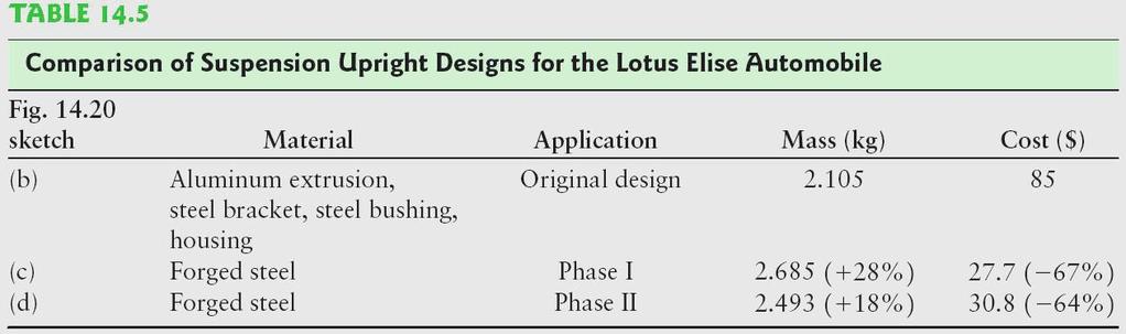
 optimized steel forging design for new car models. Source: (a) Courtesy of Fox Valley Motorcars. (b) through (d) Courtesy of Lotus Engineering and the American Iron and Steel Institute.")
38 (a) The Lotus Elise Series 2 automobile. (b) illustration of the original design for the vertical suspension uprights, using an aluminum extrusion. (c) retrofit design, using a steel forging. (d) optimized steel forging design for new car models. Source: (a) Courtesy of Fox Valley Motorcars. (b) through (d) Courtesy of Lotus Engineering and the American Iron and Steel Institute.
39