Welding Simulations with LS-DYNA
|
|
|
- Jeffrey McCoy
- 5 years ago
- Views:
Transcription


1 Welding Simulations with LS-DYNA d - Recent Developments- Dr.-Ing. Thomas Klöppel DYNAmore GmbH 1

2 Simulation of the manufacturing process chain For modern processes and materials, the mechanical properties of the finished part highly depend on the fabrication chain Tooling has to be compensated for springback and shape distortions which occur in the fabrication chain Numerical simulations of the complete process chain necessary to predict finished geometry and properties The individual stages pose very different requirements on the numerical solver 2
3 Recent development topics Realistic description of the heat source applied to the weld seam For curved geometries For deforming structures (thermal expansion during welding) Heat sources with power density distribution other than Goldak COMBINATIONS OF THE ABOVE Microstructure evolution within the material Phases changes due to heating and cooling Transformations induce strains, plasticity, change in mechanical properties and thermal porperties Valid description for a wide range of steel and aluminium alloys How to deal with application without additional material in the welded zone? 3
4 Goldak Double Ellipsoid heat source Double ellipsoidal power density distribution proposed in [Goldak2005] Most widely used for industrial applications Can be defined in LS-DYNA using keyword *BOUNDARY_THERMAL_WELD 4


5 *BOUNDARY_THERMAL_WELD Card 1 PID PTYP NID NFLAG X0 Y0 Z0 N2ID Card 2 a b cf cr LCID Q Ff Fr Opt. Tx Ty Tz NID: Node ID giving the location of weld source NFLAG: Flag controlling motion of source EQ.1: source moves with node EQ.0: fixed in space N2ID: Second node ID for weld beam direction GT.0: beam is aimed from N2ID to NID EQ.-1: beam aiming direction is (Tx, Ty, Tz) 5
 allows defining the translation and")

6 Movement of the heat source 1 Beam motion (e.g. *BOUNDARY_PRESCRIBED_MOTION_RIGID) allows defining the translation and rotation of the heat source For previously deformed or curved structures, the description of the heat source is NOT straight-forward [Schill2014] Movement of the part has to be compensated for 6
7 Movement of the heat source 2 Useful keyword: *CONTACT_GUIDED_CABLE Card 1 NSID PID CMULT WBLCID CBLCID TBLCID It forces beams in PID onto the trajectory defined by nodes in NSID [Schill2014] Possible solution Select a trajectory on the weld seam Define contact between this trajectory and a beam B1 (N1 and N2) Define a second trajectory and a beam B2 (N3 and N4) following it in a prescribed manner Welding torch aiming directions from N3 to N1 (*BOUNDARY_THERMAL_WELD) Define local coordinate system N1,N2,N3 Use *BOUNDARY_PRESCRIBED_MOTION_RIGID_LOCAL to move heat source 7
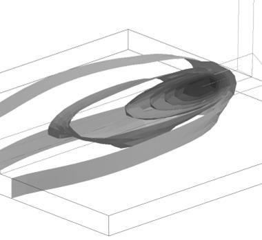
![Movement of the heat source - example [Schill2014] 2 nd](/docs-images/89/100391817/images/8-0.jpg "traj. for coordinate system Weld torch traj.")
8 Movement of the heat source - example [Schill2014] 2 nd traj. for coordinate system Weld torch traj. for torch 8

9 Movement of the heat source - example 9
 allows defining the translation and rotation of the heat source For previously deformed or curved")
![structures, the description of the heat source is NOT straight-forward [Schill2014] Movement of the part has to be compensated for The](/docs-images/89/100391817/images/10-2.jpg "incremental heating when using the Goldak heat source leads to element distortion when a too large timestep is used.")
10 Movement of the heat source Beam motion (e.g. *BOUNDARY_PRESCRIBED_MOTION_RIGID) allows defining the translation and rotation of the heat source For previously deformed or curved structures, the description of the heat source is NOT straight-forward [Schill2014] Movement of the part has to be compensated for The incremental heating when using the Goldak heat source leads to element distortion when a too large timestep is used. The mechanical solver is needed to move the heat source even though this should be solvable using only the thermal solver. 10
11 A new heat source - Approach Move the heat source movement to a new keyword. The heat source follows a prescribed velocity along a node path (*SET_NODE) The weldpath is continuously updated No need to include the mechanical solver *SET_NODE_LIST ,11877,11893,11909,11925,


12 A new heat source - Approach Move the heat source movement to new keyword. The heat source follows a prescribed velocity along a nodepath The weldpath is continuously updated No need to include the mechanical solver Use sub-timestep for integration of heat source Weld source evaluated at thermal timesteps Weld source integrated between thermal time steps 12
13 *BOUNDARY_THERMAL_WELD_TRAJECTORY Card 1 PID PTYP NSID1 VEL1 SID2 VEL2 NCYC Card 2 IFORM LCID Q LCROT LCMOV LCLAT DISC Card 3 P1 P2 P3 P4 P5 P6 P7 P8 Opt. Tx Ty Tz NSID1: VEL1: Node set ID defining the trajectory Velocity of weld source on trajectory LT.0: VEL1 is load curve ID for velocity vs. time SID2: Second set ID for weld beam direction GT.0: S2ID is node set ID, beam is aimed from these reference nodes to trajectory EQ.0: beam aiming direction is (Tx, Ty, Tz) LT.0: SID2 is segment set ID, weld source is orthogonal to the segments VEL2: Velocity of reference point for SID2.GT.0 NCYC: number of sub-cycling steps 13
14 *BOUNDARY_THERMAL_WELD_TRAJECTORY Card 1 PID PTYP NSID1 VEL1 SID2 VEL2 NCYC Card 2 IFORM LCID Q LCROT LCMOV LCLAT DISC Card 3 P1 P2 P3 P4 P5 P6 P7 P8 Opt. Tx Ty Tz IFORM: Geometry for energy rate density distribution EQ.1. Goldak-type heat source EQ.2. double ellipsoidal heata source with constant density EQ.3. double conical heat source with constant density EQ.4. conical heat source 14
15 *BOUNDARY_THERMAL_WELD_TRAJECTORY Card 1 PID PTYP NSID1 VEL1 SID2 VEL2 NCYC Card 2 IFORM LCID Q LCROT LCMOV LCLAT DISC Card 3 P1 P2 P3 P4 P5 P6 P7 P8 Opt. Tx Ty Tz LCID: Load curve ID for weld energy input rate vs. time EQ.0: use constant multiplier value Q Q: Curve multiplier for weld energy input LT.0: use absolute value and accurate integration of heat DISC: Resolution for accurate integration. Edge length for cubic integration cells Default: 0.05*(weld source depth) 15
16 *BOUNDARY_THERMAL_WELD_TRAJECTORY Card 1 PID PTYP NSID1 VEL1 SID2 VEL2 NCYC Card 2 IFORM LCID Q LCROT LCMOV LCLAT DISC Card 3 P1 P2 P3 P4 P5 P6 P7 P8 Opt. Tx Ty Tz LCROT: load curve defining the rotation (α in degree) of weld source around the trajectory as function of time. LCMOV: load curve for offset of weld source in depth (t ) after rotation as funtion of time LCLAT: load curve for lateral offset (s ) after rotation as function of time welding torch trajectory α t t velocity r = r s s 16
17 *BOUNDARY_THERMAL_WELD_TRAJECTORY Card 1 PID PTYP NSID1 VEL1 SID2 VEL2 NCYC Card 2 IFORM LCID Q LCROT LCMOV LCLAT DISC Card 3 P1 P2 P3 P4 P5 P6 P7 P8 Opt. Tx Ty Tz For IFORM=1 P1: a P2: b P3: c f P4: c r P5: F f P6: F r P7: n q = 2n nfq π πabc exp nx2 a 2 exp ny2 exp nz2 b 2 c 2 17
18 *BOUNDARY_THERMAL_WELD_TRAJECTORY Card 1 PID PTYP NSID1 VEL1 SID2 VEL2 NCYC Card 2 IFORM LCID Q LCROT LCMOV LCLAT DISC Card 3 P1 P2 P3 P4 P5 P6 P7 P8 Opt. Tx Ty Tz For IFORM=2 P1: a P2: b P3: c f P4: c r P5: F f P6: F r q = 3F 2πabc 18
19 *BOUNDARY_THERMAL_WELD_TRAJECTORY Card 1 PID PTYP NSID1 VEL1 SID2 VEL2 NCYC Card 2 IFORM LCID Q LCROT LCMOV LCLAT DISC Card 3 P1 P2 P3 P4 P5 P6 P7 P8 Opt. Tx Ty Tz For IFORM=3 P1: r 1 P2: r 2 P3: r 3 P4: b 1 P5: b 2 P6: F 1 P7: F 2 q = welding torch r 1 3F 2πb(R 2 + r 2 + Rr) b 1 b 2 velocity r 1 r 2 r 3 19
20 *BOUNDARY_THERMAL_WELD_TRAJECTORY Card 1 PID PTYP NSID1 VEL1 SID2 VEL2 NCYC Card 2 IFORM LCID Q LCROT LCMOV LCLAT DISC Card 3 P1 P2 P3 P4 P5 P6 P7 P8 Opt. Tx Ty Tz For IFORM=4 P1: r 1 P2: r 2 P3: b 1 welding torch velocity r 1 b 1 r 2 r 1 q = 3 πb(r 2 + r 2 + Rr) 20

21 Example Welding on a circular trajectory Thermal-only analysis with a large time step temperature field, NCYC = 10 temperature field, NCYC = 1 21

22 Example Welding of a three-dimensionally curved T-Joint Coupled analysis Weld source direction defined with a segment set 22
23 Recent development topics Realistic description of the heat source applied to the weld seam For curved geometries For deforming structures (thermal expansion during welding) Heat sources with power density distribution other than Goldak COMBINATIONS OF THE ABOVE Microstructure evolution within the material Phases changes due to heating and cooling Transformations induce strains, plasticity, change in mechanical properties and thermal porperties Valid description for a wide range of steel and aluminium alloys How to deal with application without additional material in the welded zone? 23


24 *MAT_UHS_STEEL/*MAT_244 - Basis Material tailored for hot stamping / press hardening processes Phase transition of austenite into ferrite, pearlite, bainite and martensite for cooling Strain rate dependent thermo-elasto-plastic properties defined for individual phases Transformation induced plasticity algorithm Re-austenitization during heating User input for microstructure computations is chemical composition alone Added: Transformation induced strains Welding functionality Different transformation start temperatures for heating and for cooling *MAT_244 is only valid for a narrow range of steel alloys! Heuristic formulas connecting chemistry with mechanics fail otherwise! 24

25 Example A gear is heated, quenched, welded to a joint Martensite concentration Temperature field 25
26 *MAT_254 Started the implementation of *MAT_GENERALZE_PHASE_CHANGE Features Up to 24 individual phases User can choose from generic phase change mechanisms (Leblond, JMAK, Koistinen-Marburger, ) for each possible phase change Material will incorporate all features of *MAT_244 Phase change parameters are given in tables and are not computed by chemical composition Will be suitable for a wider range of steel alloys and aluminum alloys Parameter of the material might come from a material database or a microstructure calculation 26
27 *MAT_254 / *MAT_GENERALIZED_PHASE_CHANGE Card 1 MID RHO N E PR MIX MIXR BETA Card 2 TASTART TAEND TABCTE EPSDA0 EPSFAIL FAILMIX DTEMP TIME Card 3 PTLAW PTSTR PTEND PTX1 PTX2 PTX3 PTX4 PTX5 Card 4 PTTAB1 PTTAB2 PTTAB3 PTTAB4 PTTAB5 Card 5 PTEPS TRIP PTHEAT PTPLAS PTDAM GRAI Card 6 LCY1 LCY2 LCY3 LCY4 LCY5 LCY6 LCY7 LCY8 Card 7 LCY9 LCY10 LCY11 LCY12 LCY13 LCY14 LCY15 LCY16 Card 8 LCY17 LCY18 LCY19 LCY20 LCY21 LCY22 LCY23 LCY24 Special welding card not needed. Liquid filler can be accounted for by an additional phase Damage and failure modelling, latent heat, grain growth modelling yet to be implemented 27
28 *MAT_254 / *MAT_GENERALIZED_PHASE_CHANGE Card 1 MID RHO N E PR MIX MIXR BETA N: Number of phases in microstructure E: Young s modulus LT.0: E is load curve ID/table ID for E vs. temperature (vs. phase) PR: Poissons s ratio LT.0: E is load curve ID/table ID for PR vs. temperature (vs. phase) MIX: MIXR: Load curve ID for initial phase concentrations LC / TAB ID for mixing rule (temperature dependent) 28
29 *MAT_254 / *MAT_GENERALIZED_PHASE_CHANGE Card 2 TASTART TAEND TABCTE EPSDA0 EPSFAIL FAILMIX DTEMP TIME TASTART: Annealing start temperature TAEND: Annealing end temperature TABCTE: coefficient of thermal expansion (CTE) LT.0: TABCTE is load curve ID/table ID for CTE vs. temperature (vs. phase) DTEMP: TIME: Maximum temperature variation within a time step time scale 29
30 *MAT_254 / *MAT_GENERALIZED_PHASE_CHANGE Card 3 PTLAW PTSTR PTEND PTX1 PTX2 PTX3 PTX4 PTX5 Card 4 PTTAB1 PTTAB2 PTTAB3 PTTAB4 PTTAB5 PTLAW: Table ID containing phase transformation laws If law ID.GT.0: used for cooling If law ID.LT.0: used for heating LAW ID : EQ.1: Koistinen-Marburger EQ.2: JMAK EQ.3: Kirkaldy (only cooling) EQ.4: Oddy (only heating) PTSTR: Table ID containing start temperatures PTEND: Table ID containing end temperature PTXi: i-th scalar parameter (2D table input) PTTABi: i-th temperature dependent parameter (3D table input) 30
31 *MAT_254 / *MAT_GENERALIZED_PHASE_CHANGE Card 3 PTLAW PTSTR PTEND PTX1 PTX2 PTX3 PTX4 PTX5 Card 4 PTTAB1 PTTAB2 PTTAB3 PTTAB4 PTTAB5 Koistinen Marburger: Evolution equation: x b = x a 1.0 e α(t start T) Parameter: PTX1: α 31
32 *MAT_254 / *MAT_GENERALIZED_PHASE_CHANGE Card 3 PTLAW PTSTR PTEND PTX1 PTX2 PTX3 PTX4 PTX5 Card 4 PTTAB1 PTTAB2 PTTAB3 PTTAB4 PTTAB5 Johnson-Mehl-Avrami-Kolmogorov (JMAK): Evolution equation: dx b dt = n T k Parameter: PTTAB1: n(t) PTTAB2: x eq (T) PTTAB3: τ(t) PTTAB4: f(t ) PTTAB5: f (T ) abx a k ab x b ln k ab x a + x b k ab x a k ab k ab = x eq T τ T f T, k ab = 1.0 x eq T τ T x b f T n T 1.0 n(t) 32
33 *MAT_254 with JMAK First example: Phase change test for steel S420 33
34 *MAT_254 / *MAT_GENERALIZED_PHASE_CHANGE Card 3 PTLAW PTSTR PTEND PTX1 PTX2 PTX3 PTX4 PTX5 Card 4 PTTAB1 PTTAB2 PTTAB3 PTTAB4 PTTAB5 Kirkaldy (equivalent to *MAT_244): Evolution equation: dx b dt = 20.5 G 1 f C Parameter: PTX1: f C PTX2: n T PTX3: n 1 PTX4: n 2 PTTAB1: D(T) PTTAB2: Y X b PTTAB3: x eq (T) T start T n TD T X n X b b 1.0 n Xb 2 X b Y X b, x b = X b x eq (T) 34
35 *MAT_254 / *MAT_GENERALIZED_PHASE_CHANGE Card 3 PTLAW PTSTR PTEND PTX1 PTX2 PTX3 PTX4 PTX5 Card 4 PTTAB1 PTTAB2 PTTAB3 PTTAB4 PTTAB5 Oddy (equivalent to *MAT_244): Evolution equation: dx b dt = n x a c 1 T T c start 2 ln x a + x b x a n 1.0 n Parameter: PTX1: n PTX2: c 1 PTX3: c 2 35
36 *MAT_254 / *MAT_GENERALIZED_PHASE_CHANGE Card 5 PTEPS TRIP PTHEAT PTPLAS PTDAM GRAI PTEPS: TRIP: GRAIN: Table ID for transformation induced strains Flag for transformation induced plasticity (active for TRIP.gt.0) Initial grain size 36
37 Effect of DTEMP Rapid heating and cooling of a single element Non-linear strains as transformation induced strains and the coefficient of thermal expansion depend on the temperature Results for small time steps can be reproduced if DTEMP is sufficiently small 37
38 Residual stresses Nitschke-Pagel test temperature longitudinal stresses equiv. plastic strain transversal stresses 38


39 Residual stresses Nitschke-Pagel test LS-DYNA Exp. Reference Num. Reference LS-DYNA Exp. Reference Num. Reference 39
40 Recent development topics Realistic description of the heat source applied to the weld seam For curved geometries For deforming structures (thermal expansion during welding) Heat sources with power density distribution other than Goldak COMBINATIONS OF THE ABOVE Microstructure evolution within the material Phases changes due to heating and cooling Transformations induce strains, plasticity, change in mechanical properties and thermal porperties Valid description for a wide range of steel and aluminium alloys How to deal with application without additional material in the welded zone? 40
41 Welding without filler elements Ghost element approach is not suitable for all welding processes No material might be added in the process Significant sliding of parts before welding New contact formulation *CONTACT_AUTOMATIC_SURFACE_TO_SURFACE_TIED_WELD_THERMAL As regions of the surfaces are heated to the welding temperature and come into contact, the nodes are tied Regions in which the temperature in the contact surface is always below the welding temperature, standard sliding contact is assumed Heat transfer in the welded contact zones differs as compared to unwelded regions Right now, only implemented for contact between solid elements, but Dave Benson is working on a shell to shell version right now 41
42 *CONTACT_AUTOMATIC_SURFACE_TO_SURFACE_TIED_WELD_THERMAL Card 4 TEMP CLOSE HWELD Card 5 K Hrad H0 LMIN LMAX CHLM BC_FLAG 1_WAY Card4 is read if TIED_WELD is set TEMP: Welding temperature CLOSE: maximum contact gap for which tying is considered HWELD: Heat transfer coefficient for welded regions Card5 is standard for THERMAL option H0: Heat transfer coefficient for unwelded regions 42

43 *CONTACT_AUTOMATIC_SURFACE_TO_SURFACE_TIED_WELD_THERMAL Example: butt weld During welding the blocks are allowed to move Assumption: Insulation in unwelded state, perfect heat transfer after welding 43

44 Thank you! 44