The new material irradiation infrastructure at the BR2 reactor. Copyright 2017 SCK CEN
|
|
|
- Madeleine Knight
- 5 years ago
- Views:
Transcription

1 The new material irradiation infrastructure at the BR2 reactor
2 The new material irradiation infrastructure at the BR2 reactor Steven Van Dyck, Patrice Jacquet

3 Characteristics of the BR2 MODULE 1 reactor Overview 3
 25MW additional cooling capacity for experiments n th n f Achievable flux")
: 1 10 13 n/cm²s to 6 10 14 n/cm²s Allowable heat flux in primary coolant 470W/cm² for the driver fuel plates Demineralised water Pressure to 1.")
4 Reactor core performance of BR2 Design goal: thermal neutron flux up to n/cm 2 s Achievement by Compact core arrangement with central flux trap Material choice: Be moderator and metallic uranium fuel High overall core power (upgraded from 50 to 100MW in 1968) 25MW additional cooling capacity for experiments n th n f Achievable flux levels (at mid plane in vessel) Thermal flux: n/cm 2 s to n/cm 2 s Fast flux (E>0.1MeV): n/cm²s to n/cm²s Allowable heat flux in primary coolant 470W/cm² for the driver fuel plates Demineralised water Pressure to 1.2MPa, temperature C 10m/s flow velocity on fuel plate Up to 600W/cm² can be allowed in experiments
5 Spectral tailoring in BR2 experiments Objective Simulation of fast reactor conditions Separation between transmutation and lattice damage Method Selection of irradiation position in reflector or fuel element Addition of absorbing materials n [n.cm-2.s-1] with Cd-screen without Cd-screen Neutron energy [MeV]
 and bottom (17) Irradiation inside rigs in reactor channel or in axis of fuel element Loading elements hang on")
6 Reactor core geometry Diverging reactor channels for compact core and good access: core 1m, cover 2m Angle of channels from 0 to 27 Reactor channels accessible from top (all) and bottom (17) Irradiation inside rigs in reactor channel or in axis of fuel element Loading elements hang on top cover
7 Overview of typical irradiation positions Channel type thermal flux range (10 14 n/cm²s) fast flux range (10 14 n/cm²s) (E>1MeV) Gamma heating (W/g Al) diameter (mm) typical number available F1 1 to to to F2 up to 2.5 up to 2.5 up to * S 1 to to to ** Central large channel H1 up to 10 up to *** Peripheral large channel Hi **** Peripheral small channel P 0.7 to to to
8 Flexible reactor configuration Combination of multiple experiments in core load Position of fuel, control rods and experiments are optimised Choice of type of fuel elements Adapted reactor power and cycle length Reactor load is optimised for each operating cycle 3D MCNP model with burn-up evolution of entire core Detailed model of experiment if required Verification by measurement before start BR2 reactor management is ISO 9001 certified (including irradiations)
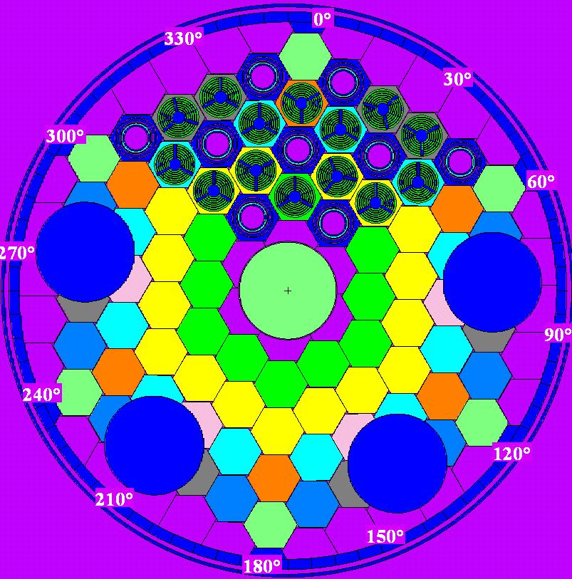

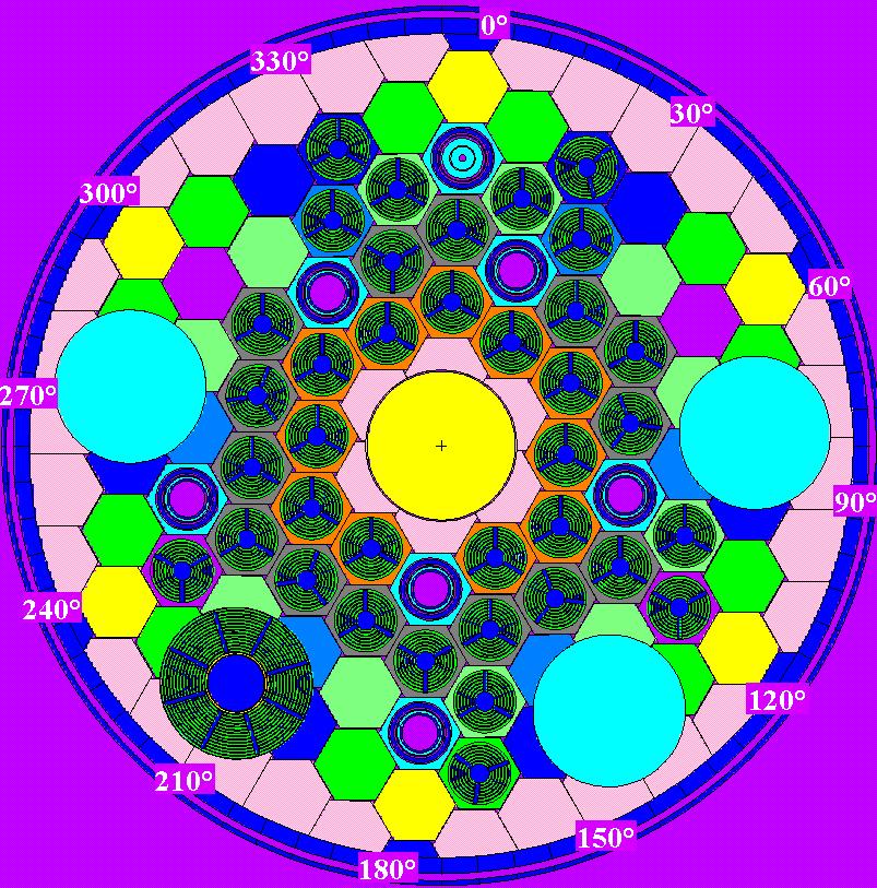


9 Typical configuration variants in BR2


10 BR2 = Multipurpose Reactor Thimble tube Driver Fuel Element Fuel Experiment Control Rod Si NTD 192 Ir Basket 99 Mo PRF Materials Experiment Mid-plane cross section of a typical BR2 core

11 New material irradiation devices
12 Material irradiation for selection and qualification New applications of nuclear energy Issue: application target is beyond current database Higher temperatures Higher (fast neutron) fluence Different environments Materials: wide variation for screening Stainless & high chromium steels: GEN 3&4 Ceramics & cermets: ATF claddings & fusion Copper, tungsten, steel: fusion Solutions Provide rigs with high flexibility in irradiation conditions Select high fast flux positions: 0.5 dpa / cycle Provide cost effective solutions for irradiation of many samples
13 Purpose of the device Specimens (not fuel) irradiation at HTHF High Temperature High Flux High temperature : C (measured and controlled) High flux: in a VIn fuel element (dose up to 10 dpa) Nuclear Heating from 8 up to 14 W/g Specimens: Type: flat tensile, mini-charpy & simple geometries (like cylinders) Material: High temperature resistant: W, Mo, SiC, Fe (300 C) No requirement to preheat specimens at irradiation temperature before the first neutron. Environment: gas (Helium) or vacuum 13/16
14 Material irradiation for GEN 4/fusion conditions The High Temperature High Flux device High dose rate (>0.5 dpa per reactor cycle) Stable irradiation temperature during irradiation Low cost rig with flexible loading position in reactor Solution Gas filled capsule inside 6 plate fuel element and electrical heating Control of temperature by gas gap design and gas pressure Miniature specimens Characteristics Temperature C Single use capsule Up to 0.75 dpa per reactor cycle of 3 weeks fluence 4.7 to 5.2E20 n/cm² (E>1MeV) in hottest channel


15 HTHF Design concept 1 - Graphite sheath 2 Graphite matrix for mini-charpy 3 Graphite cover 4 Graphite pen 5 Graphite centering plug 6 Graphite matrix for flat tensile 7 Graphite cover Locking Pen Specimens Sheath Matrix Hole for Dosimeter Hole for Heating wire Holes for Thermocouples 15/16
16 HTHF Calculation results Temperature profile +/- flat over predefined range. (+/- 1% at calculated pressure) Measurements of temperature at max 4 levels.
17 Irradiation behavior Strong temperature dependence on nuclear heating Optimisation of temperature feedback on temperature control Strong gradient between W samples and C matrix Electric power Reactor power Helium pressure
18 Optimised control: irradiation cycle 2
19 Fast flux at mid plane during first 2 cycles 1, n/cm²s and 1, n/cm²s Accumulated damage after 2 cycles 0,42dpa in W Neutron spectrum 1,4E+14 1,2E+14 Irradiation conditions HTHF Cycle 05/2017 Flux (neutrons.cm -2.s -1.u -1 1E+14 8E+13 6E+13 4E+13 2E ,0E-09 1,0E-07 1,0E-05 1,0E-03 1,0E-01 1,0E+01 Neutron Energy (MeV)
20 Material irradiation in support of long term operation Irradiation induced ageing of reactor pressure vessel steels Issue: current files from surveillance programmes insufficient for LTO Insufficient material Low lead factor Challenge Provide validated datasets compatible with existing surveillance programmes Solution Relevant dose levels for Long Term Operation Sufficient volume/ numerous specimens Representative and controlled temperature Provide a rig with stable temperature control in low to moderate flux position (0.X dpa in one or 2 reactor cycles) Validate data on standardised specimen type against surveillance data from plant Generate new data beyond database on newly irradiated samples
21 The new RECALL device Requirement: material irradiation in typical LWR conditions Loading of full size Charpy specimens (>10) Stable irradiation temperature before, during & after irradiation ( C) Flux levels relevant for LWR plant life management: 0.05 to 0.15 dpa per reactor cycle of 3 weeks Solution Reusable rig with flexible loading position in reactor Short lead times Limited impact on other experiments Variable position in reactor yields wider range of dose rates >16 Charpy specimens in flux range >85% maximum
 RECALL rig concept 8 7 6 5")

22 neutron fluence (10 19 n/cm², E>1MeV) RECALL rig concept Left Right axial position (mm)
23 RECALL operation Pressurised water is injected at low temperature in IPS Saturation pressure set to stabilize irradiation temperature Preheating to irradiation temperature Heating of samples before start of irradiation Evacuation of nuclear heating by nucleate boiling Stable irradiation temperature independent of heat flux Injection of cold water Control of steam fraction and reactivity effect (void factor)
24 Temperature distribution

25 Steam fraction as function of cold water injection
26 Expected fast flux distribution in needles & structure
27 2 new devices are presented for material irradiation High fast flux device for multi-cycle dpa accumulation: HTHF Low fast flux device for ageing studies with strict temperature control: RECALL Utilisation of flexibility of reactor Conclusions Selection of fuel element with similar heating over cycles: HTHF Creation of reflector position with desired fluence over 2 cycles and rotation at mid experiment: RECALL Cost effectiveness and short lead times Generic design method and re-use of OPE: HTHF Reloadable device in reactor pool or hot-cell: RECALL