Materials development for fusion application
|
|
|
- Bertina Spencer
- 5 years ago
- Views:
Transcription
1 Materials development for fusion application Natalia Luzginova Materials Consultant 1
2 Outline Introduction The ITER project Main components and materials Materials selection and challenges Beyond ITER New materials development Summary 2
3 Fission Reactors Introduction DEMO References: 1. Nuclear Energy Today OECD/Nuclear Energy Agency Fusion Electricity - EFDA November Fusion Reactors ITER 3
4 Introduction ITER is a large-scale scientific experiment 4

5 Introduction ITER is a large-scale scientific experiment Location: Cadarache, Provence, France Time frame: first plasma 2020; first fusion reaction

6 Introduction ITER is a large-scale scientific experiment Location: Cadarache, Provence, France Time frame: first plasma 2020; first fusion reaction 2027 March 2015 Photo by Natalia Luzginova 6

7 Introduction deuterium tritium helium neutron and lots of energy! Fusion reaction 7
8 Introduction ITER is a large-scale scientific experiment Location: Cadarache, Provence, France Time frame: first plasma 2020; first fusion reaction 2027 The ITER Agreement was signed by China, the European Union, India, Japan, Korea, Russia and the United States 8
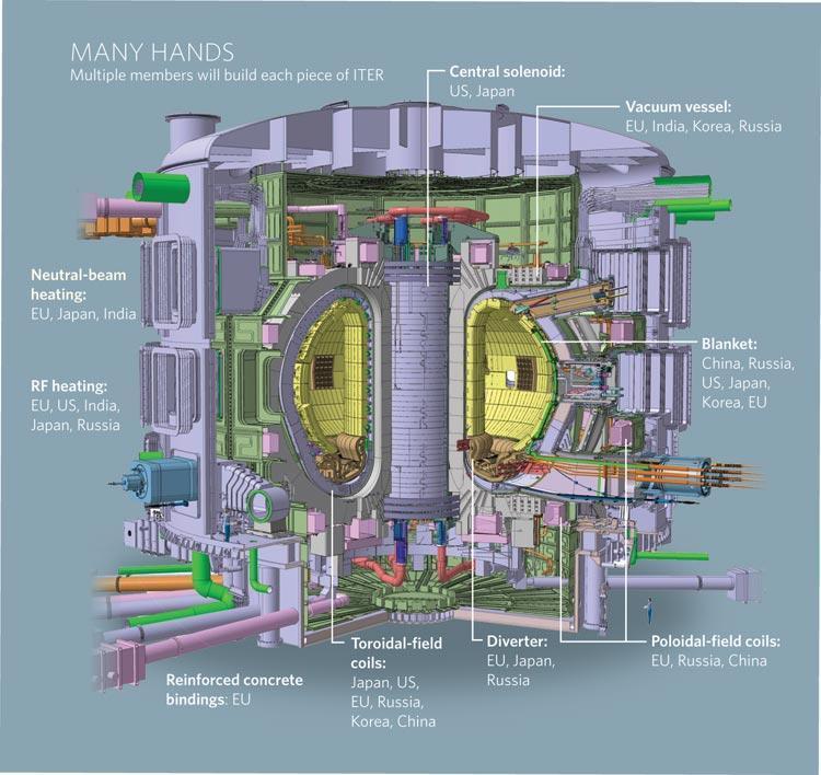
9 ITER (overview) 9
10 Introduction Fusion advantages No air pollution or greenhouse gases No risk of a nuclear accident No high-level waste Abundant fuel supply Fusion challenges Unknown technology 10
11 Outline Introduction The ITER project Main components and materials Materials selection and challenges Beyond ITER New materials development Summary 11
12 Main components and materials Materials for the ITER components have been selected based on Nuclear design codes Extensive R&D programs carried out by ITER parties Comprehensive assessments of the various functional, design, safety, operational and technological requirements 12

13 Main components and materials Picture from ITER Organization 13

14 Materials selection ITER vacuum vessel The vacuum vessel is a hermetically-sealed steel container inside the cryostat that houses the fusion reaction and acts as a first safety containment barrier 14 Picture from ITER Organization
15 Materials selection ITER vacuum vessel 316L(N)-IG steel is selected based on more than 30 years of experience from fast-breeder reactor applications in France and EU IG ITER Grade accommodates additional ITER requirements for steel composition Radioprotection (Co, Nb, Ta) Magnetic permeability < 1.03 Inclusion content (vacuum requirements) Additional limit for P, S 15

16 Materials selection Neutron effects on 316L(N)-IG steel have been extensively studied and assessed Strengthening and loss of ductility Loss of strain hardening However, at doses up to 1 dpa it is a ductile material G. Kalinin, MPH

17 Materials selection Neutron effects on 316L(N)-IG steel have been extensively studied and assessed Fatigue no effects Fracture toughness reduction, but material is still ductile 17
18 Challenges Nuclear components in the fusion reactors may face repairs or (partial) replacements: Vacuum vessel sectors In-vessel components Coolant tubes and piping Replacement or repair of the failed components Re-welding of irradiated stainless steel problematic -> cracking in the heataffected and fusion zones 18 Picture from ITER Organization
19 Challenges He is formed in austenitic stainless steels by the reaction of thermal neutrons and alloying elements: 58 Ni + n 59 Ni + 59 Ni + n 56 Fe + 4 He; 10 B + n 7 Li + 4 He Ni is an alloying element in 316L(N) steel B is an impurity element coming from scrap material He is practically insoluble in metal 19
20 Challenges To minimize the probability of crack formation during re-welding, it is recommended* to minimize He content in the irradiated material < appm for multi-pass welding < 1-3 appm for single pass (thin pipe) low energy welding The exact limitation of He content for sound reweldability depends on the welding method and material * V. Barabash, First Joint ITER-IAEA Technical Meeting, 2010, Monaco 20 Picture from ITER Organization
21 Challenges Re-welding after irradiation Regime I - heat-up period before temperature reaches the melting point Regime II - peak temperature period Regime III - weld solidification * H.T. Lin, et.al., 1990, Met. Trans. A. 21
22 Heat Input (J/mm) Heat Input vs. Helium Content single pass no micro and macro cracks single pass micro cracks single pass micro and macro cracks multipass no micro and macro cracks multipass micro cracks multipass micro and macro cracks appm for thick plates 1-3 appm for thin pipes Helium contents (appm) *Wang [1996], Asano [1998/2000]; Schuring [2000/2001], van Thoor [2001/2002], Luzginova [2010/2011] 22
23 Fission Reactors Fusion power plant DEMO References: 1. Nuclear Energy Today OECD/Nuclear Energy Agency Fusion Electricity - EFDA November Fusion Reactors ITER 23
24 Outline Introduction The ITER project Main components and materials Materials selection and challenges Beyond ITER New materials development Summary 24

25 Advanced materials Advanced nuclear systems require high performance materials Excellent Creep Properties? Radiation Tolerance Corrosion resistance VHTR Very High Temperature Reactor SCWR Supercritical Water Reactor GFR Gas Fast Reactor LFR Lead Fast Reactor SFR Sodium Fast Reactor MSR Molten Salt Reactor 25
26 Advanced materials Requirements for materials for fusion application Attractive high temperature physical and mechanical properties High radiation resistance Low activation for recycling potential Reliable manufacturing processes New structural materials Basic performance: Reduced activation ferritic/martensitic (RAFM) steel Enhanced performance: Oxide dispersion strengthened (ODS) steel 26


27 RAFM steel 9Cr steel Why 9Cr steel? --> Minimum of DBTT around 9 wt.% Cr Tavassoli, et.al, JNM, 2014 Tempered martensitic microstructure Schuring,

28 RAFM steel 9Cr steel Why 9Cr steel? --> Minimum of DBTT around 9 wt.% Cr Tavassoli, et.al, JNM,
29 RAFM steel 9Cr steel Why Ferritic/martensitic structure? --> Good swelling resistance P. Yvon,
 of 1.5x10 27 n/m 2 at 533 ºC F. A. Garner, PNNL 30")
30 RAFM steel 9Cr steel Why Ferritic/martensitic structure? --> Good swelling resistance P. Yvon, 2009 Fast fluence (E>1.0 MeV) of 1.5x10 27 n/m 2 at 533 ºC F. A. Garner, PNNL 30

31 RAFM steel 9Cr steel Starting material is a T91steel (9Cr/1Mo/0.2V/0.08Nb) W as a solution hardener Ta as a carbide former 31
 989-996 Eurofer97 is manufactured by Böhler 32")
32 RAFM steel 9Cr steel Reduced Activation: Low level waste already after years The Eurofer97 specification is a result of 20 years R&D effort R. Lindau et al., Fusion Eng. and Design (2005) Eurofer97 is manufactured by Böhler 32

33 RAFM steel Eurofer97 steel A.-A.F. Tavassoli,
34 RAFM steel Eurofer97 steel Ferritic/martensitic steel Eurofer97 will be used in the ITER Test Blankets Modules (TBM s) developed in EU, and it is the main structural material of the Breeding Blankets Modules for DEMO reactor. 34
 zoomed in ITER Blanket (in yellow) is a layered")
 and then stainless")
35 Where is TBM in ITER? Vacuum vessel (stainless steel) zoomed in ITER Blanket (in yellow) is a layered component, where first layer is Be - facing plasma. The rest of the Blanket is high-strength copper (for heat sink) and then stainless steel (structural material). TBM (in green) It is a box built of Eurofer97 steel Pictures from ITER Organization 35
36 RAFM steel Eurofer97 steel Ferritic/martensitic steel Eurofer97 will be used in the ITER Test Blankets Modules (TBM s) developed in EU, and it is the main structural material of the Breeding Blankets Modules for DEMO reactor Limitations The maximum operational temperature for Eurofer97 steel is 550 o C Possible solution Development of Oxide Dispersion Strengthened (ODS) alloys 36

37 RAFM steel ODS steel Rainer Lindau, KIT,
38 RAFM steel ODS steel Combination of nano-sized oxide particles and fine grains is believed to result in improved high-temperature strength/creep properties microstructural stability under irradiation and high resistance to radiationinduced swelling Y. de Carlan et al., Mechanical Properties of Nuclear ODS Alloys, 2012 Iracane et al., Generation IV Systems; R&D needs and research reactors policy,

39 RAFM steel ODS steel 39

40 RAFM steel ODS steel 40
41 RAFM steel ODS steel ODS steels have better high temperature/creep properties There are promising results on microstructural stability under irradiation Key technological issues: Industrial scale production and processing of ODS steels Mechanical properties before, under and after irradiation ODS steel joining/welding Interaction with coolant 41
42 Summary Materials for ITER have been selected based on comprehensive assessment of many different requirements Fusion power plant will require new material that can withstand harsh fusion conditions Both RAFM and ODS steels are showing promising results. However, materials R&D is not yet completed 42

43 Thank you for your attention