Fullerene Resists. Optimizing RLS. J. Manyam, R.E. Palmer, A.P.G. Robinson Nanoscale Physics Research Laboratory, The University of Birmingham
|
|
|
- Cecily Brown
- 5 years ago
- Views:
Transcription
1 Fullerene Resists Optimizing RLS J. Manyam, R.E. Palmer, A.P.G. Robinson, The University of Birmingham M. Manickam, J.A. Preece School of Chemistry, The University of Birmingham


2 Resists for Next Generation Lithography Shrinking the RLS Tradeoff Conventional Polymeric Resist Molecular Resist PMMA fragment Fullerene Dose Dose Resolution LWR LWR Resolution Simulations indicate that molecular resists may shrink the RLS tradeoff * * D. Drygiannakis et al, Microelectron. Eng, 84, 1062 (2007)
3 Fullerene Resists C 60 photopolymerisation was first demonstrated by Rao *. hν Electron beam resist behaviour was first shown by Tada. e - Insoluble Graphitic Material *A.M. Rao, et al, Science, 259, 955 (1993) T. Tada, et al, Jpn. J. Appl. Phys., 35, L63 (1996)
4 Fullerene Resists Advantages of C 60 Resist: Disadvantages of C 60 Resist: Very high etch resistance High resolution (< 20 nm) Very low sensitivity (10 mc/cm 2 ) Coating by vacuum sublimation Improving the C 60 Resist: Derivatise to improve solubility R R

5 Fullerene Resists 20 nm linewidth Dose = 30,000 pc/cm at 30 kev PAB = None PEB = None Develop = 10 s, MCB Rinse = 10 s, IPA
6 The Sensitivity Problem LMW Resists typically have poor sensitivity - the best fullerene resist sensitivity is ~ 370 µc/cm 2. Solution Chemical Amplification to enhance sensitivity Photoacid Generator hν H T Unexposed Resist Exposed Resist CA Schematic after: H. Ito, Adv. Polym. Sci., 172, 37 (2005),
7 MF07-01 Resist System Methanofullerene: MF07-01 Photoacid Generator (mixed triarylsulfonium hexafluroantimonate salts) + Epoxy Crosslinker
8 MF07-01 Synthesis Yield MF07-01 %
9 Epoxy Crosslinker Name CL1-1 CL1-2 CL1-3 ~Mn Epoxies Poly[(phenyl glycidyl ether)-co-formaldehyde] CL2-1 CL2-2 CL2-3 CL Poly[(o-cresyl glycidyl ether)-co-formaldehyde]
10 Sensitivity vs Composition Exposure = 20 kev Develop = MCB:IPA [1:1] PAB PEB = 75 ºC for 600 s = 90 C for 180 s
11 Sensitivity vs Crosslinker CL PAB (ºC/s) PEB (ºC/s) CL2-1 CL1-1 CL2-2 CL1-1 CL1-2 CL1-3 75/300 80/600 None 90/180 90/ /60 CL1-2 CL1-3 CL2-3 CL2-4 CL2-1 CL2-2 CL2-3 CL2-4 None 75/600 75/600 75/600 90/180 90/180 90/180 90/180 Exposure = 20 kev Develop = MCB:IPA [1:1]


![[1:1] Rinse = 10 s, IPA 25 nm](/docs-images/89/100989439/images/12-2.jpg "Half Pitch Dose = 140 pc/cm PAB")

12 MF07-01 : CL2-4 : PAG 17 nm Linewidth Dose = 240 pc/cm at 30 kev PAB = None PEB = 90 C for 180 s Dev = 10 s, MCB:IPA [1:1] Rinse = 10 s, IPA 25 nm Half Pitch Dose = 140 pc/cm PAB = 75 ºC for 600s PEB = 90 C for 180 s Dev = 10 s, MCB:IPA [1:1] Rinse = None


13 MF07-01 : CL2-4 : PAG 50 nm Half Pitch 35 nm Half Pitch 30 nm Half Pitch 25 nm Half Pitch
14 MF07-01 : CL2-4 : PAG 15 nm Sparse Features


15 MF07-01 : CL2-4 : PAG PEB Process Latitude 75 ºC 90 ºC 105 ºC 1 min 5 min

16 MF07-01 : CL2-4 : PAG 18 nm Linewidth LWR = 2.4 (LER ~ 1.7 nm)

![= 90 C for 180 s Dev = 10 s, MCB:IPA [1:1]](/docs-images/89/100989439/images/17-1.jpg "Rinse = 10 s, IPA 20 nm Half Pitch Dose =")

17 MF07-01 : CL1-1 : PAG 12 nm Linewidth Dose = 300 pc/cm at 30 kev PAB = 75 ºC for 600s PEB = 90 C for 180 s Dev = 10 s, MCB:IPA [1:1] Rinse = 10 s, IPA 20 nm Half Pitch Dose = 140 pc/cm PAB = 75 ºC for 600s PEB = 90 C for 180 s Dev = 10 s, MCB:IPA [1:1] Rinse = None

18 MF07-01 : CL1-1 : PAG 18 nm hp Dense Pattern


19 MF07-01 : CL1-1 : PAG PEB Process Latitude 75 ºC 90 ºC 105 ºC 1 min 5 min
20 Line width (nm) All Crosslinkers Sparse Line Dose Process Latitude CL0603 CL1-1 CL0604 CL1-2 CL0609 CL2-1 CL0610 CL2-4 CL0801 CL2-3 CL0802 CL Line dose (pc/cm)


21 Etch Durability Etch resistance (resist to silicon) PAB no PAB 0 SAL601 A B C D E F SAL601 CL1-1 CL1-2 CL2-1 CL2-4 CL2-2 CL2-3 Crosslinker CL nm pitch Si structures 25 nm half pitch Si structures


22 MF07-01 : CL2-4 : PAG New Resist Aged 7 days Aged 30 days

, and exposures were done with")

23 EUV Exposure at PSI 50 nm Half Pitch in CL2-4 Exposure time at PSI was kindly provided by Intel Corp, (Dr M.J. Leeson), and exposures were done with the assistance of Drs H. Solak, V. Auzelyte and P. Sahoo of the Paul Scherrer Institute
24 Line Width Roughness Sparse Resolutions of 12 nm and dense resolutions of 20 nm have been achieved at < 10 µc/cm 2 sensitivities. Line width roughness is typically about 4-5 nm, but 2.5 nm has been seen under certain circumstances. Currently studying line width roughness in relation to: Dose Line Pitchwidth Pitch PEB PEB PAB PAB Crosslinker PAG Concentration PAG Type Base Quencher Concentration Casting Solvent Developer LWR measured with IMEL Demokritos software

25 LWR vs Dose Dose (pc/cm) MF07-01:CL1-1:PAG (1:2:1), PAB 75ºC, 10 m; PEB 90ºC, 3 m
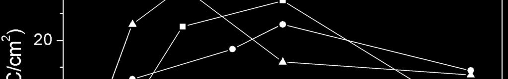
26 LWR vs Dose 10 9 CL1-1 CL CL2-1 CL2-2 CL2-3 CL2-4 Line Width Roughness (nm) Line Width Roughness (nm) Line Dose (pc/cm) Line Dose (pc/cm) PAB 75ºC, 10 m PEB 90ºC, 3 m Composition [1:2:1] Crosslinker Variable Casting Solvent Chloroform Developer MCB:IPA [1:1] Rinse IPA Feature Type Sparse
27 LWR vs Crosslinker 10 Sparse Dense Line Width Roughness (nm) PAB 75ºC, 10 m PEB 90ºC, 3 m Composition [1:2:1] Crosslinker Variable Casting Solvent Chloroform Developer MCB:IPA [1:1] Rinse IPA Dose Optimal 0 None CL1-1 CL1-2 CL2-1 CL2-2 CL2-3 CL2-4 Crosslinker
28 LWR vs Pitch pC/cm 240pC/cm 280pC/cm 320pC/cm pC/cm 240pC/cm 280pC/cm 320pC/cm Line Width Roughness (nm) Line Width (nm) Pitch (nm) Pitch (nm) PAB 75ºC, 10 m PEB 90ºC, 3 m Composition [1:2:1] Crosslinker CL1-1 Casting Solvent Chloroform Developer MCB:IPA [1:1] Rinse IPA Feature Type Variable
29 LWR vs PEB C 1min 90C 1min 105C 1min C 5min 90C 5min 105C 5min Line Width Roughness (nm) Line Width Roughness (nm) Line Dose (pc/cm) Line Dose (pc/cm) PAB 75ºC, 10 m PEB Variable Composition [1:2:1] Crosslinker CL2-4 Casting Solvent Chloroform Developer MCB:IPA [1:1] Rinse IPA Feature Type Sparse
30 LWR vs PAG Concentration Line Width Roughness (nm) wt% 20 wt% 25 wt% 29 wt% 33 wt% 37 wt% 40 wt% Line Width (nm) wt% 20 wt% 25 wt% 29 wt% 33 wt% 37 wt% 40 wt% Line Dose (pc/cm) Line Dose (pc/cm) PAB PEB Composition Crosslinker 75ºC, 10 m 90ºC, 3 m Variable CL1-1 Casting Solvent Chloroform Developer MCB:IPA [1:1] Rinse IPA Feature Type Sparse
31 LWR vs Base Concentration Line Width Roughness (nm) wt% 2.5 wt% 5.0 wt% 7.5 wt% 10 wt% Line Width (nm) wt% 2.5 wt% 5.0 wt% 7.5 wt% 10 wt% Line Dose (pc/cm) Line Dose (pc/cm) PAB 75ºC, 10 m PEB 90ºC, 3 m Composition [1:2:1] Crosslinker CL-1-1 Casting Solvent Chloroform Developer MCB:IPA [1:1] Rinse IPA Feature Type Sparse
32 LWR vs Casting Solvent 10 9 Anisole PGMEA Chloroform 30 Anisole PGMEA Chloroform Line Width Roughness (nm) Line Width (nm) Line Dose (pc/cm) Line Dose (pc/cm) PAB 75ºC, 10 m PEB 90ºC, 3 m Composition [1:2:1] Crosslinker CL1-1 Casting Solvent Variable Developer MCB:IPA [1:1] Rinse IPA Feature Type Sparse
 The process latitude is good. Preliminary ageing data indicates that they are stable.")
33 Conclusions CL2-4: Resolution 17nm (sparse) CL1-1: Resolution 12 nm (sparse) 25 nm (dense) 20 nm (dense) Sensitivity 6 µc/cm 2 13 µc/cm 2 LWR 4 nm (sparse) 4.3 nm (sparse) 7.1 nm (dense) 6.4 nm (dense) The process latitude is good. Preliminary ageing data indicates that they are stable. The etch durability is equivalent to commercial novolac resists, and patterns can be transferred with ECR SF 6 etching. LWR Studies are on-going: Increasing dose does not improve LWR PAG level needs to be optimized (more not necessarily better) Some base is beneficial (too much increases LWR) Slow or hot PEB seems beneficial Casting Solvent is important Best combination: R = 15.3 nm (sparse), LWR = 2.3 nm, S = 600 pc/cm R = 13.5 nm (sparse), LWR = 2.3 nm, S = 200 pc/cm


34 Acknowledgments Mr J. Manyam, Ms M-Y. Song, Mr J. Lawton, Mr C. Jones, Dr J. Yin, Dr A. Pulisciano, Dr H Zheng, Dr F.P. Gibbons, Dr H.M. Zaid, Dr J.C. Barnard, Dr A.J. Parker, Dr M.R.C. Hunt, Prof. R.E. Palmer, University of Birmingham Dr U. Jonas, Prof. F. Diederich Laboratorium für Organische Chemie, ETH Zentrum, Switzerland Dr S. Diegoli, Dr M. Manickam, Dr E.J. Shelley, Dr D. Philp, Dr M.T. Allen, Prof. K.D.M. Harris, Prof. J.A. Preece School of Chemistry, The University of Birmingham, UK Dr E. Tarte, Dr C. Anthony, Dr. J. Teng School of Engineering, The University of Birmingham, UK Dr T. Tada, Dr T. Kanyama Joint Research Center for Atom Technology, NAIR, Japan Dr C. Figgures Sowerby Research Centre, BAe Systems, UK Dr J. Mackevich, Dr R. Brainard, Dr T. Zampini, Dr K. O Connell Rohm and Haas (Electronic Materials), Marlborough USA Dr J.H. Tortai CNRS, France Dr L. Rumiz Sincrotrone Trieste S.C.p.A., Italy Dr M.J. Leeson Intel Corp Dr H. Solak, Dr V. Auzelyte, Dr P. Sahoo Paul Scherrer Institute, Switzerland more Moore
35 Thank you Questions?