Oil Country Tubular Ltd. INDIA. ISO 9001 : 2015 Company
|
|
|
- Mitchell Ellis
- 5 years ago
- Views:
Transcription


1 Oil Country Tubular Ltd. INDIA ISO 9001 : 2015 Company


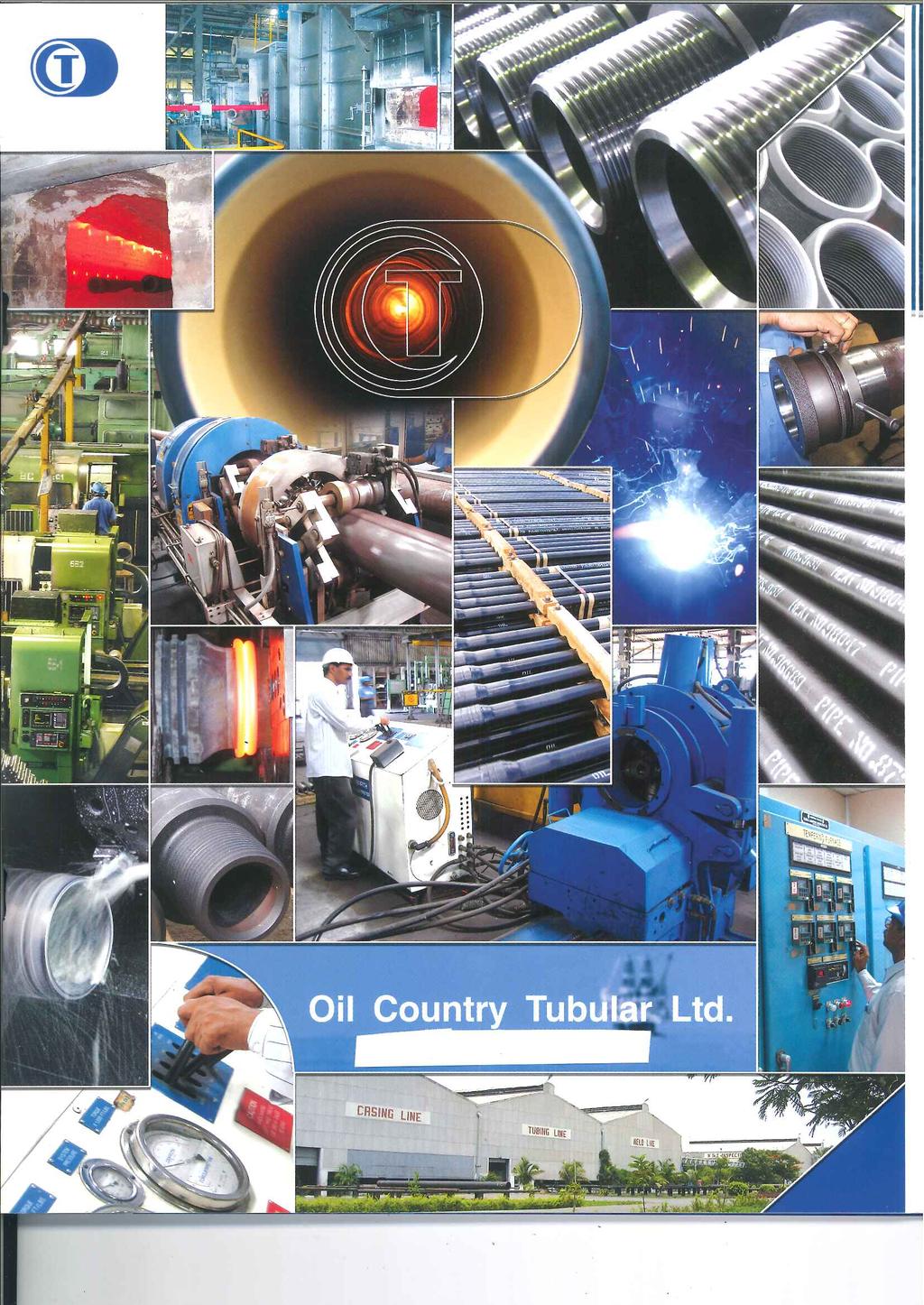
2 m Oil Country Tubular Ltd. ISO 9001 :2015 Company Manufacturer/ Processor of Oil Country Tubular Goods Drill Pipes/ Heavy Weight Drill Pipes/ Drill Collars Production Tubing ( API & Premium Connections) Casing Pipes (API & Premium Connections) Couplings, Pup-Joints & Cross Overs Oil Field Accessories & Services Repair/ Reconditioning of Drill Pipes/ Premium Connections Field Inspection Services Certification/ Accreditation ISO 9001 : 2015 API Specification- SOP API Specification- 7-1 API Specification- SCT Registration No. SDP-0065 Registration No Registration No. SCT-0243
3 INTRODUCTION Oil Country Tubular Limited (OCTL), is one of the leading companies in the World processing a wide range of Oil Country Tubular Goods required for the Oil Drilling and Exploration Industry. OCTL is an ISO 9001:2015 Company and is licensed by American Petroleum Institute (API) under API Specifications 5DP, 5CT and 7-1. The products are manufactured to the relevant API Specifications and carry API monogram. OCTL is located near Hyderabad city, India, and is an unique integrated facility in the World. OCTL has earned worldwide recognition for the Quality of its products and services. Innovation and Technical Excellence are the driving spirit behind OCTL and the overriding focus at OCTL is on the quality of its products and services. At OCTL, the complete processing activity is concentrated in a single unique Integrated Plant located at Narketpally with Corporate Head Quarters in Hyderabad, India. The facilities include Upsetting, Heat Treatment of Tubulars, Non- Destructive Testing, Metallurgical Laboratory, Gaging and Calibration Laboratory, Tool Joint and Coupling Heat Treatment and Threading, Hardfacing of Tool Joints, Casing and Tubing Threading, Friction Welding of Drill Pipe, Hydrostatic Testing and Internal Plastic Coating of Tubulars. Research and Development activities are continuous phenomena at OCTL aimed at upgradation of technology and manufacturing processes. OCTL s wide product range covers Drill Pipe, Heavy Weight Drill Pipe, Drill Collars, Production Tubing, Casing, Tool Joints, Couplings, Pup Joints, Rotary Subs, and Cross Overs. 1
, Stabilizer Sleeves, Welded Blade Stabilizers and")
4 Oil Country Tubular Ltd. OCTL s Oil Field Accessories include Rotary Subs, Lift Plugs and Lift Subs, Cross Overs (Drill Pipe to Drill Collar or Drill Collar to Drill Collar), Stabilizer Sleeves, Welded Blade Stabilizers and Cast Steel Lifting Bails. Services include Tool Joint Hardfacing, Make and Break of Tool Joints, Internal Plastic Coating of Drill Pipe and Tubing, Reconditioning of Drill Pipe, Re-threading of Drill Pipe, Heavy Weight Drill Pipe, Drill Collars, Tubing and Casing, Repair and Rethreading of Premium Tubing and Casing, and Field Inspection of Tubulars. OCTL can also manufacture and supply in large numbers finished Tool Joints and API Couplings for Tubing and Casing of all grades. In addition to the manufacture of API Products, OCTL is also a licensee for the manufacture of high performance Premium Connections including Two Step Premium Connections RTS-6, RTS-6PR, RTS-8, RTS-8PR, RSU-6, RSU-8 for Tubing and RFC, RSS for Casing. OCTL is also licensed for many other Premium Connections from time to time and OCTL takes pride in being a source for Premium Connections of high quality with a competitive edge, besides offering repair facilities for such connections. OCTL believes in the principles of continuous improvement, which are put into practice at every level in the organization. It is OCTL s continuous endeavor to improve the quality of its products and services to the complete satisfaction of it s Customers, by adopting the latest manufacturing techniques, practices and technical improvements. OCTL s sophisticated equipment, expertise and technology makes it the best option to manufacture and supply the product to the customer s complete satisfaction. Our integrated facility gives us the competitive edge ; ably supported by our personnel who are highly motivated, dedicated and committed to produce Quality products consistently.
5 QUALITY Oil Country Tubular Limited was established to meet the growing worldwide demand for Oil Country Tubular Goods of the highest quality by ensuring compliance with American Petroleum Institute Specifications and the OCTL Standards. OCTL endeavors to provide the best products and services to meet the exacting needs of its customers. Quality is of paramount importance at OCTL. In the pursuit of this goal, the OCTL Quality Assurance Program actively involves personnel at all levels, in the continuing effort to produce the highest level of quality products consistently. At OCTL, Quality is a continuous process and is embedded in every event, right from the receipt of the Customer Order, procurement of raw materials, processing and shipment of the finished products. The Customer Order is reviewed for all the specifications and special customer requirements and is translated to manufacturing documents. The incoming raw material procured only from High Quality Mills from all over the World, approved by OCTL, are verified for conformance to the chemistry and dimensional parameters stipulated in the OCTL Metallurgical Specifications, prior to processing.

6 Oil Country Tubular Ltd. During each of the processing stages, strict quality controls are performed to ensure the highest levels of Quality and full compliance with the specified requirements. The best controls, testing, inspection concepts, and practices are integrated into the system. The inspection procedures are designed to detect imperfections, assess their severity and assure that all products comply with the specified standards. These include mechanical and metallurgical testing, nondestructive testing for possible longitudinal and transverse defects, wall thickness and steel grade verification, pipe hardness, drift, hydrostatic testing, magnaflux and ultrasonic inspection, and threading inspection. To accomplish this, the facility is equipped with the latest testing and inspection equipment s, Metallurgical Laboratory including ARL Spectrometer for chemical analysis, and Metrology Laboratory for gages and tooling control. A complete set of Master and Working Gages are maintained and the calibration of the gages is strictly scheduled for verifying Working Gages against Master Gages, as well as all the inspection, measuring, and testing equipment. Complete documentation is provided with each shipment detailing the full Quality Control records covering the Mill Test and Inspection Certificate, Quality Clearance Certificate, Length Tally, Drill String Assembly data (for Drill Pipe), Non-destructive Test Certificate and Warranty Certificate. Any other documentation can also be included on Customer s request. At any time, the Customer can be provided with a comprehensive account of his product. OCTL, a complete integrated facility with the quality conscious personnel having the required expertise at all levels, presents itself as the best option to manufacture and supply Quality products consistently with the Competitive Edge to your complete satisfaction. The OCTL Quality Assurance Program provides complete process and product traceability for each pipe, starting from the raw material stage through finishing. A unique product number is die stamped on every product to ensure complete traceability. All the Tests and Inspection results throughout the manufacturing process and product traceability data are fully documented and maintained in a computerized data base and are traceable with the product number. We stand committed to total quality and customer satisfaction
7 DRILL PIPE OCTL offers a complete range of Drill Pipe with Tool Joints attached from 2 m" OD to 5 a" OD according to API Specification 5DP and guidelines presented in API RP7G and Premium Specifications. Drill Pipes with 95% Remaining Body Wall and Extra Long Tool Joints and Extra Long Internal Taper and Special s are also offered upon Customer s request. Holiday Free Internal Plastic Coating is also offered upon Customer s request. OCTL Drill Pipe and Tool Joints are manufactured from the finest quality steel available. Each step of the manufacturing process is performed with the highest degree of accuracy to meet or exceed API Specifications as well as the Industry Standards. Plain End Pipes and Tool Joint Forgings are procured to specific metallurgical chemistries and are matched for physical properties, welding compatibility, weld strength and product integrity. Plain end pipe is upsetted and heat-treated full length by the Quench and Temper process to achieve uniform mechanical properties. The upset profile is designed to blend with the inside diameter of the pipe body with a generous radius giving a smooth transition from the thicker cross section of the upset to the pipe body. The smooth transition minimizes the stress concentrations. The heat-treated pipe is tested for tensile and impact properties and are 100% non-destructively inspected for possible longitudinal and transverse defects, wall thickness and grade verification. Dry magnetic particle inspection of the upset ends is done to ensure that the upsets are free from defects. The OD & ID and face of the upsets are CNC machined for a clean surface as part of pipe preparation prior to welding. 5
8 Oil Country Tubular Ltd. Tool Joint Forgings are turned, bored and faced prior to heat treatment by the Quench and Temper process to produce a uniform microstructure, high ductility, and other mechanical properties in accordance with API Specifications. The heat treatment is done under controlled atmosphere for consistent quality. The hardness of every tool joint is checked by Brinell Hardness Tester and recorded. The tensile and impact properties are verified by destructive testing of a tool joint representing each process batch. Every tool joint is subjected to wet magnetic particle inspection, both transverse and longitudinal, to insure the absence of defects. Threads are precision machined on CNC lathes. All connections are 100% inspected for thread parameters and phosphatized either with Zinc or Manganese for antigalling treatment. Tool Joints are attached to the drill pipe tube by friction welding to produce a high integrity solid state weld connection between the tool joint and the upset drill pipe tube. The process involves the rotation of one surface against a second surface at a relatively high speed and under heavy pressure. The friction between the tool joint surface and the pipe surface generates heat, causing the contact surfaces to reach a high temperature, below the melting temperature, at which they are forged together, producing the weld. Every weld is monitored and recorded in a strip chart. The OD and ID weld rams are removed by shearing and machining. Post weld heat treatment of the heat-affected zone between the drill pipe upset and the tool joint is carried out to restore the properties of the weld zone. The post weld heat treatment is a Quench and Temper process by which the weld zone is first brought to its austenitizing temperature, and then polymer quenched. An area wider than the weld zone is then re-heated by induction to tempering temperature. Every post weld heat treatment is monitored and recorded in a strip chart. Each weld is 100% inspected for hardness to confirm that they were adequately tempered. The post weld heat treatment process consistently produces stronger, tougher, and more uniform weld properties and a desirable microstructure, which maximizes the resistance to stress and fatigue. Surfaces adjacent to the weld line are smooth finished on both the OD and ID. Precision machining and grinding provides a surface finish that is free of stress risers. Each weld area is 100% inspected using wet magnetic particle and ultrasonic inspection techniques. Destructive testing of the weld covering tensile, yield, impact and bend tests are carried out for every defined lot and are documented. The Quality Control involves sampling at defined and random intervals for process control. All the tests and inspection results and product traceability data are fully documented and maintained in a computerized data base. At any time, the Customer can be provided with a comprehensive account of his product.

9 DRILL PIPE Traceability For each drill pipe component, complete product and process traceability is maintained from the raw material to the completion of all the manufacturing. For the pin and box tool joints, the mill test certificates are confirmed by incoming testing and each tool joint is provided with a unique product number and this product number gives the traceability through out the manufacturing process. The same procedure is applied to the pipe for it s traceability. Complete documentation is provided with each shipment detailing the full Quality Control records covering, Quality Clearance Certificate Length Tally Sheet Drill String Assembly Data, which includes the product number of each component (Pin and Box and Pipe), heat numbers of each component, finished length, upset to upset length & weight of each pipe. Mill Test & Inspection Certificate that includes chemical analysis for all pipe and tool joints, mechanical results of pipe and upset and tool joints and mechanical results of test welds. Non Destructive Test Certificate Any other documentation per Customer s request can also be provided. Options available on customer s request: Extra Long Tool Joints: to provide increased space for connection rework and for tong handling. 7 Make and Break of Tool Joints: break the joints in by making up three times to their recommended make-up torque. This option ensures proper initial make-up of tool joints, which affects the life of the tool joint connections. Saves rig time.

10 Oil Country Tubular Ltd. Cold Rolling: of thread roots to create a pre-stress compression loading condition which increases fatigue life by increasing resistance to crack initiation. Hardfacing of Tool Joints SmoothX : provides a smooth surface with little or no exposed carbide to minimize the tool joint wear Super SmoothX : for applications requiring maximum casing protection provided by a machine or grind finish surface CASING PLUS : for a very hard but smooth surface that simultaneously protects both the tool joint and the casing in which it is run. ARNCO 100XT TM, ARNCO 200XT TM, ARNCO 300XT TM : Provides low coefficient of friction to reduce casing wear, as well as provide a high resistance to rapid abrasive wear on the tool joint. ARMACOR M TM : Provides a low coefficient of friction and high wear resistance to prevent casing wear as well as abrasive wear on the tool joint. TCS 8000 TM : Chromium- alloy hardbanding material reduces wear on tool joints and on well casings. TCS Titanium TM : Contains Titanium- carbides which are harder than Tungsten- carbides increasing tool joint protection and is casing friendly. Internal Plastic Coating Internal Plastic Coating of Drill Pipe improves the performance and life of the drill pipe. The Drill Pipe is thermal cleaned and the internal surface is blasted with grit for a good anchor pattern preparatory to Coating. A two stage application of phenolic / epoxy liquid coatings is sprayed on to the internal surface of the drill pipe in a controlled manner and thermal cured at each stage. This ensures uniform coating thickness and Quality throughout the length of the Drill Pipe. The finished Drill Pipe is externally coated with rust preventive varnish, attached with Thread Protectors and Skid Bundled with utmost care. Our integrated facility gives us the Competitive Edge to manufacture and supply Drill Pipe to your Complete Satisfaction. SmoothX SuperSmoothX CASING PLUS are registered trademarks of Grant Prideco, Inc. ARMACOR M TM is a registered trademark of Amorphous Metals Technologies, Inc. ARNCO 100XT TM, ARNCO 200XT TM, ARNCO 300XT TM are registered trademarks of Arnco Technology Trust. TCS 8000 TM and TCS Titanium TM are trademarks of Varco I/P, Inc. or it s subsidiaries and registered with U.S. Patent and Trade Office.

11 Drill Pipe Manufacturing Schedule * Optional: Hardfacing, Internal Plastic Coating Mechanical Properties of API Drill Pipe s Yield Strength Tensile Strength Minimum Maximum Minimum Group PSI MPa PSI MPa PSI MPa 1 E-75 75, , , * 5DP 3 X-95 95, , , * 5DP G , , , * 5DP S , , , * 5DP * API formula e = 625,000 A 0.2 /U 0.9, Where : e minimum elongation in 2 inches in percent rounded to nearest ½ percent. A cross sectional area of the tensile test specimen in square inches, based on specified outside diameter, or nominal specimen width, and specified wall thickness, rounded to the nearest 0.01 sq., or 0.75 sq. in whichever is smaller. U specified tensile strength, psi. Mechanical Properties of Tool Joint Minimum Yield Strength Maximum Yield Strength Maximum PSI MPa PSI MPa PSI MPa 120, , , Elongation % Minimum Elongation % Minimum API Specification on API Specification on
12 DRILL PIPE SCHEDULE Oil Country Tubular Ltd. Drill Pipe Specifications Tool Joint Specifications Tool Joint Size Nominal Steel Calculated Inside Wall Outside Inside Bevel Diameter Total Designation and Weight Plain End Diameter Thickness Diameter Diameter of Length Type weight of Pin & Box of Pin Pin and Box Tool Joint Pin of Non upset +1/32 +1/64 Shoulder +1/4 Upset -1/32-1/32 +1/64 3/8 D d D F L P lb/ft lb/ft NC-26 (2-3/8 IF) 2-3/8 EU 6.65 E /8 1-3/4 3 17/64 10 X /8 1-3/4 3 17/64 10 G /8 1-3/4 3 17/64 10 NC-31 (2-7/8 IF) 2-7/8 EU E /8 2-1/8 3 61/ /2 X / / /2 G / / /2 S /8 1-5/8 3 61/ /2 NC-38 (3-1/2 IF) 3-1/2 EU 9.50 E /4 2-11/ / /2 NC-38 (3-1/2 IF) 3-1/2 EU E /4 2-11/ /64 12 X / /64 12 G / /64 12 S /8 4 37/64 12 NC-38 (3-1/2 IF) 3-1/2 EU E / /64 12 X / /64 12 G /8 4 37/64 12 NC-40 (4 FH) S /2 2-1/4 5 1/ /2 NC-40 (4 FH) 4 IU E /4 2-13/16 5 1/ /2 X /4 2-11/16 5 1/ /2 G /2 2-7/16 5 1/ /2 S / / /2 NC-46 (4 IF) 4 EU E /4 5 23/ /2 X /4 5 23/ /2 G /4 5 23/ /2 S / /2 NC-46 (4 IF) 4-1/2 IU E /8 5 23/ /2 NC-46 (4 IF) 4-1/2 IEU E /4 3-1/4 5 23/ /2 X / / /2 G / / /2 S /4 2-3/4 5 23/ /2 NC-46 (4 IF) 4-1/2 IEU E / / /2 X /4 2-3/4 5 23/ /2 G /4 2-1/2 5 23/ /2 S /4 2-1/4 5 23/ /2 NC-50 (4-1/2 IF) 4-1/2 EU E /8 3-3/4 6 1/ /2 NC-50 (4-1/2 IF) 4-1/2 EU E /8 3-3/4 6 1/ /2 X /8 3-3/4 6 1/ /2 G /8 3-3/4 6 1/ /2 S /8 3-1/2 6 1/ /2 NC-50 (4-1/2 IF) 4-1/2 EU E /8 3-5/8 6 1/ /2 X /8 3-1/2 6 1/ /2 G /8 3-1/2 6 1/ /2 S / / /2 NC-50 (4-1/2 IF) 5 IEU E /8 3-3/4 6 1/ /2 X /8 3-1/2 6 1/ /2 G /8 3-1/4 6 1/ /2 S /8 2-3/4 6 1/ /2 NC-50 (4-1/2 IF) 5 IEU E /8 3-1/2 6 1/ /2 X / / /2 G /8 2-3/4 6 1/ /2 NC-50(5-1/2 FH) 5 IEU E /4 6 23/32 13 X /4 6 23/32 13 G /4 6 23/32 13 S /4 3-1/2 6 23/32 13 NC-50(5-1/2 FH) 5 IEU E /2 6 23/32 13 X /2 6 23/32 13 G /4 3-1/2 6 23/32 13 S /4 3-1/4 6 23/32 13 NC-50(5-1/2 FH) 5-1/2 IEU E /32 13 X /4 6 23/32 13 G /4 3-1/2 6 23/32 13 S / /32 13 NC-50(5-1/2 FH) 5-1/2 IEU E /32 13 X /4 3-1/2 6 23/32 13 G /4 3-1/2 6 23/32 13 S / /32 13 All dimensions are in inches Neck diameters (D PE and D TE ) and inside diameters (d) of tool joints prior to welding are at manufacturer s option. The dimensions given are after final machining of the assembly. The Tool Joint designation indicates the size and style of the connection. Nominal weights are shown for the purpose of identification.
13 t Specifications Total Pin Tong Box Tong Combined Diameter Length Space Space Length of of l Joint Pin Pin & Box Pin & Box +1/4 +1/4 +1/4 +1/2 at Elevator 3/8-1/2 Upset, max. L P L PB Tool Joint Specifications PE, D TE Torsional Ratio Pin to Drill Pipe PB L B L D PE, / / / / / / / / / / / / /2 18 1/2 3 7/ /2 18 1/2 3 7/ /2 18 1/2 3 7/ /2 18 1/2 3 7/ /2 18 1/2 3 7/ /2 18 1/2 3 7/ /2 18 1/2 3 7/ /2 18 1/2 3 7/ / / / / / / / / / / / / / / / / / / / / / / / / / / / / / / / / / / / / / / / / / / / / / / / / / / / / / / / / / / / / / / / / / / / / / / / / / / / the assembly. The inside diameter does not apply to Box members, which are optional with the manufacturer. 11
14 Oil Country Tubular Ltd. Charpy V-Notch Longitudinal absorbed energy requirements as per American Petroleum Institute (API) and OCTL Specifications Impact Values for Tool Joints Specimen Size (mm x mm) 10x10 10 x x 5.0 Minimum Average Absorbed Energy Ft/lb (J) 40 (54) 32 (43) 22 (30) OCTL / API Specification Minimum Specimen Absorbed Energy Ft/lb (J) 35 (47) 28 (38) 19 (26) Test Temperature: 70 ºF±5 ºF (21±3 ºC) NA: Not Applicable Impact Values for Test Welds Specimen Size (mm x mm) 10x10 10 x 7.5 Minimum Average Absorbed Energy Ft/lb (J) 12 (16) 10 (14) Test Temperature: 70 ºF±5 ºF (21±3 ºC) API Specification Minimum Specimen Absorbed Energy Ft/lb (J) 10 (14) 8 (11) Minimum Average Absorbed Energy Ft/lb (J) 32 (43) 26 (35) OCTL Specification Minimum Specimen Absorbed Energy Ft/lb (J) 27 (37) 22 (30) Impact Values for Drill Pipe body: (for Group - 1 & Group - 3) Specimen Size (mm x mm) 10x10 10 x x 5.0 Minimum Average Absorbed Energy Ft/lb (J) 40 (54) 32 (43) 22 (30) Test Temperature: 70 ºF±5 ºF (21±3 ºC) API Specification Minimum Specimen Absorbed Energy Ft/lb (J) 35 (47) 28 (38) 19 (26) OCTL Specification Impact Values for Drill Pipe body under PSL-3 (All grades) Specimen Size (mm x mm) 10x10 10 x x 5.0 Minimum Average Absorbed Energy Ft/lb (J) 74 (54) 59 (80) 41 (56) Test Temperature: -4 ºF±5 ºF (-20±3 ºC) Minimum Specimen Absorbed Energy Ft/lb (J) 59 (80) 47 (64) 32 (43) OCTL Specification Same as API -do- -do- Same as API -do- -do- Alternate Low Temperature Charpy V-Notch Impact requirements as per SR20 for all grades can be provided on request.
15
16 Oil Country Tubular Ltd. HEAVY WEIGHT DRILL PIPE OCTL Heavy Weight Drill Pipe consists of two extra long tool joints and one central heavy wall tube. The tool joints are friction welded to the central heavy wall tube. The tool joints are manufactured from AISI 4145 H modified material, fully heat treated to Brinell hardness and 40 ft-lbs. minimum Charpy V-notch Impact strength. All other physical properties conform to API Specification 7-1. The central heavy wall tube is manufactured from AISI 1340 steel or equivalent. Features OCTL Heavy Weight Drill Pipe is manufactured in compliance with API Specification 7-1 and API RP 7G. Bore Back on Box ends and API Stress Relief Groove on Pin ends are standard for all sizes. Thread roots are cold worked on all sizes for durability. All connections are phosphatized to help prevent galling during make-up, coated with API thread compound and provided with pressed steel or cast steel thread protectors with lifting bails. To optimize wear resistance, hardbanding is standard on tool joints and central upset. Standard hardbanding includes one 4 wear pad on both pin and box end, plus one 1 pad on taper section of box to prevent fluid cutting and two 3 wear pads on central upset to prevent wear on the pipe section. The hardbanding is completely flush on both tool joints and l oversize on the central upset (fully flush on request). Hardbanding materials include crushed sintered tungsten carbide of mesh, Arnco 100 XT TM, Arnco 200XT TM, Arnco 300XT TM, Armacor-M TM, and TCS 8000 TM or TCS Titanium TM TM. Internal Plastic Coating, if required (optional). Quality Control A rigorous quality assurance program is maintained at every manufacturing step. Each Heavy Weight Drill Pipe joint is fully inspected by an ultrasonic unit full length. The Mechanical Properties, dimensions, and thread inspections are recorded on the Inspection Certificate. Every connection is 100% dimensionally inspected and recorded. Spiral Heavy Weight Drill Pipe Spiral Heavy Weight Drill Pipe consists of three spiral upsets equally spaced between the tool joints. Spiral Heavy Weight Drill Pipe features more weight per foot and better hole cleaning characteristics than standard Heavy Weight Drill Pipe, providing optimum performance in severe drilling conditions. MANUFACTURING SCHEDULE Nominal Size (A) ID Dimensions (inches) Wall Center Upsets (C) Tube Tool Joint Approx. Unitized Weight (lbs.) End Upsets (B) Mechanical Properties Tensile Yield (lb) Torsional Yield (ft-lb) Connection Size and Type OD (D) HEAVY WEIGHT DRILL PIPE / SPIRAL HEAVY WEIGHT DRILL PIPE ID Mechanical Properties Tensile Yield (lb) Torsional Yield (ft-lb) Heavy Weight Drill Pipe per foot per Joint (30 6 ) Spiral Heavy Weight Drill Pipe per foot per Joint (30 6 ) Make-up Torque (ft-lb) 3 1 / / / 345,400 19,580 NC 38 (3 1 / 2 IF) 4 3 / 4 or / / ,800 17, , / / / NC 38 ( ,500 18,460 / 2 IF) 4 3 / 4 or 4 7 / / 4 700,400 17, , / / / ,500 27,640 NC 40 (4 FH) 5 1 / 4 or 5 3 / / ,400 24, , / / / ,100 40,720 NC 46 (4 IF) 6 1 / 4 or 6 3 / / 4 1,024,500 38, , ,281 22, / NC 50 ( / 8 691,200 56,500 / 2 IF) 6 1 / 2 or 6 5 / 8 3 1,265,700 51, , ,536 29, / / / ,400 75, / 2 FH 7 1 / / 4 1,449,700 64, , / / / / 16 1,021, , / 8 FH 8or8 1 / / 2 1,580,500 73, , , ,278 40,600 45,800
17 HEAVY WEIGHT DRILL PIPE SPIRAL HEAVY WEIGHT DRILL PIPE Mechanical Properties Tool ool Joint (AISI 4145) Central Heavy Wall all Tube ube (AISI 1340) Yield Strength M (psi) 120,000 55,000 Tensile Strength M (psi) 140,000 95,000 On enquiries and orders, please specify: Nominal Size / Range / Hardbanding / Spiral or Non Spiral / Internal Plastic Coating, if required. 15
 are manufactured from AISI 4145 H Chromium Molybdenum Alloy Steel and are fully heat treated to a Brinell Hardness range of 285-341 BHN and have a")
18 Oil Country Tubular Ltd. DRILL COLLARS OCTL Drill Collars (Slick and Spiral) are manufactured from AISI 4145 H Chromium Molybdenum Alloy Steel and are fully heat treated to a Brinell Hardness range of BHN and have a minimum Charpy V-notch Impact strength of 40 ft-lbs. at 70 F and a minimum elongation of 13%. The mechanical properties meet or exceed API Specification 7-1, requirements. The physical properties are guaranteed one inch below the surface at ambient room temperature. MECHANICAL PROPERTIES (4145 H CHROMIUM MOLYBDENUM ALLOY STEEL) Drill Collar OD () 3 1/8 to 6 7/8 7to11 Minimum Yield Strength (psi) 110, ,000 Minimum Tensile Strength (psi) 140, ,000 Minimum Hardness (BHN) Drill Collars are precision trepanned to close bore tolerance and all bores are drifted to API Specification 7-1. The connections are cut on Drill Collar Manufacturing Schedule Drill Collar Diameter 3 1 / / / / / / / / / / / / / / Bore +1/16-0" 1 1 / / / / / / / / / / / / / / / / / Connection NC 23 (2 3 / 8 REG) NC 26 (2 3 / 8 IF) NC 31 (2 7 / 8 IF) NC 35 NC 38 (3 1 / 2 IF) NC 44 NC 44 NC 44 NC 46 (4 IF) NC 46 (4 IF) NC 46 (4 IF) NC 46 (4 IF) NC 50 (4 1 / 2 IF) NC 50 (4 1 / 2 IF) NC 50 (4 1 / 2 IF) NC 56 NC / 8 API REG NC / 8 API REG NC 70 NC / 8 API REG Approximate Weight Drill Collar lb / ft Bending Strength Ratio 2.57:1 2.42:1 2.43:1 2.58:1 2.38:1 2.49:1 2.84:1 2.91:1 2.63:1 2.76:1 3.05:1 3.18:1 2.54: :1 2.70:1 3.02:1 2.93:1 3.17:1 2.81:1 2.57:1 2.81:1 2.84:1 CNC Machines. All API connections comply with dimensional requirements specified in API Spec 7-1 and guidelines presented in API RP 7G. The thread roots as well as elevator and slip recess upper radii are systematically cold rolled to improve fatigue resistance of the connections by minimizing crack initiation. To improve resistance to galling all connections are phosphatized and coated with an API thread compound. The connections are provided with pressed steel or cast steel thread protectors. Spiral Drill Collars To avoid differential pressure sticking in the hole, the surface of drill collars can be provided with three spiral grooves reducing the contact area with the wall of the hole. The spiral grooves let mud circulate freely around the Drill Collar to equalize pressure and prevent a seal from forming. Loss of weight is approximately 4%, compared to Slick Drill Collars. SPIRAL SLICK NOTE: Standard API tolerances on length is +/- 6 inches. Drill Collars of all other intermediate sizes or different dimensions can be manufactured on customer's request.
19 Slip and Elevator Recesses Dimensions Drill Collar Diameter OD 4 1 / / / / / / / / / / Elevator Recess Diameter A 3 11 / / / / / / / / / / / / / / / 8 Slip Recess Diameter B 3 3 / / / / / / / / / / / / / / / 2 Elevator Recess Radius R 1 / 8 1 / 8 1 / 8 1 / 8 1 / 8 1 / 8 3 / 16 3 / 16 3 / 16 3 / 16 3 / 16 3 / 16 1 / 4 1 / 4 1 / 4 1 / 4 1 / 4 API Stress Relief Features and API Bore Back Box decrease the frequency of fatigue failures by improving the bending strength of pin and box connections, thereby, reducing high stress concentrations. Stress relief features are machined in compliance with API Specification 7-1. Connections NC23, NC 26 (2 m IF) and NC 31 (2 o IF) do not have sufficient metal to accommodate stress relief features. Slip and Elevator recesses improve handling efficiency and safety. The upper radius of the elevator recess is cold-rolled. Slip and Elevator recesses can be used together or separately. Slip and Elevator Recesses are machined in compliance with API RP 7G guidelines. Hardbanding Drill Collars with slip and elevator recesses (ZIP) 4 long wear pad above elevator recess 1 long wear pad above slip recess 10 long wear pad under slip recess Drill Collars with slip recess 10 long wear pad under slip recess 4 long wear pad above slip recess Drill Collars without slip and elevator recesses 10 long wear pad at 30 from pin shoulder On enquiries and orders, please specify: Outside Diameter, Bore, Length, Connection Size and Type, API Stress Relief Features on Pin and Box ends, Slick or Spiral, Hard banding (band location and width), Slip or Elevator Recesses, Pressed or Cast Steel Thread Protectors, and any special features. 17
20 Oil Country Tubular Ltd. Tubing Manufacturing Schedule for Threaded & Coupled Tubing for Integral Tubing
21 TUBING 19 OCTL offers the complete range of API Tubing including Integral and Threaded and Coupled (non-upset and external upset with 8 Round or 10 Round APIconnection), from sizes 2 m" OD to 4 ½ OD in all grades according to API Specification 5CT and also Premium Connections. The Premium Connections include Two Step Premium Connections including RTS-6/ RTS-6PR/ RTS-8/ RTS-8PR/ RSU-6/ RSU-8 and many other Premium Connections that are licensed to OCTL from time to time. OCTL takes pride in being a source for Premium Connections of high quality with a competitive edge, besides offering repair facilities for the Premium Connections. The finest quality steel is used for the manufacture of Tubing. Each step of the manufacturing process is performed with the highest degree of accuracy to meet or exceed API Specifications as well as the Industry Standards. Plain End Pipe and Coupling Stocks in green condition (un-heat treated) are procured to specific metallurgical chemistries and dimensional requirements as per OCTL Metallurgical Specifications from reputed API Approved Mills only. Plain End Pipe is upsetted (where required) and heat-treated by Quench and Temper process. Each Heat Lot is tested for mechanical properties. The heat treated Tubing is 100% inspected non-destructively prior to threading. The Coupling Stock follows the same process prior to threading. The threading on the Pipe and the Couplings is done on CNC machines and 100% gaging of all the critical dimensional parameters is done and recorded as part of the manufacturing records. The finished Couplings are given antigalling treatment (Zinc or Manganese) prior to Buck-on operation. There is an on-line antigalling treatment facility with tilt tables and phosphating tanks for both ends of Premium Tubing. Computerized Torque Moitoring System is utilized for Buck-on operation. The Couplings are Bucked-on to the pipe at their specific designed buck-on torques which are recorded. All Tubing are subjected to Hydrostatic Testing as required by API Specifications. Internal Plastic Coating of Tubing can also be provided at customers option. The finished Tubing is externally coated with rust preventive varnish, installed with Thread Protectors and Skid Bundled with utmost care. Complete documentation is provided with each shipment detailing the full Quality Control records.
22 Oil Country Tubular Ltd. Tensile and Hardness requirements for Pipe and Couplings (Casing & Tubing) as per API Specification 5CT (1) (2) (3) (4) (5) (6) (7) (8) (9) (10) Yield Strength Tensile Hardness Specified Allowable Elongation Strength Maximum Wall Hardness % Minimum Thickness Variation Minimum (psi) (inches) (HRC) Group Type Minimum Maximum (psi) (psi) HRC BHN 1 H40 40,000 80,000 60,000 * J55 55,000 80,000 75,000 * K55 55,000 80,000 95,000 * N80 80, , ,000 * 2 M65 65,000 85,000 85, * L ,000 95,000 95, * L80 9Cr 80,000 95,000 95, * L80 13Cr 80,000 95,000 95, * C90 1, 2 90, , , or less 3.0 * C90 1, 2 90, , , to * C90 1, 2 90, , , to * C90 1, 2 90, , , and above 6.0 * C95 95, , ,000 * T95 1, 2 95, , , or less 3.0 * T95 1, 2 95, , , to * T95 1, 2 95, , , to * 3 P , , ,000 * 4 Q , , , or less 3.0 * Q , , , to * Q , , , and above 5.0 * e = 625,000 (A 0.2 / U 0.9 ), where : e = Minimum elongation in 2 inches in percent rounded to nearest ½ percent A = Cross sectional area of the tensile test specimen in square inches, based on specified outside diameter or nominal specimen width and specified wall thickness, rounded to the nearest 0.01 square inch, or 0.75 square inch, whichever is smaller. U = Specified tensile strength, psi.
23 API Tubing Schedule (1) (2) (3) (4) (5) (6) (7) (8) (9) (10) (11) (12) (13) Weight Designation a,b Type of End Finish c Designation a Nonupset External Integral Outside Wall T&C d Upset Joint Diameter Thickness H40 J55 L80 N80 C90 e T95 e P110 T&C () () 2 3/ N N N N N N 2 3/ NU NU NU NU NU NU NU 2 3/ NU NU NU NU NU 2 3/ U U U 2 7/ NU NU NU NU NU NU NU 2 7/ NU NU NU NU NU 2 7/ NU NU NU NU NU 2 7/ U U U 3 1/ N N N N N N 3 1/ NU NU NU NU NU NU NU 3 1/ N N N N N N 3 1/ NU NU NU NU NU N N N N N N U U U U U U 4 1/ NU NU NU NU NU NU a Designations (columns1-4) are shown for the purpose of identification in ordering. b The densities of martensitic chromium steels (L80 types 9Cr and 13Cr ) are different from carbon steels. The weights shown are therefore not accurate for martensitic chromium steels. A weight correction factor of may be used. c N = nonupset T&C; U= external-upset T&C; I= integral joint. d Nonupset tubing is available with regular couplings or special-bevel couplings. External upset tubing is available with regular, specialbevel, or special clearance couplings. e C90 and T95 tubing shall be furnished in sizes, weights, and wall thickness as listed above, or as shown on the Purchase order. 21

24 Oil Country Tubular Ltd. Casing Manufacturing Schedule for Threaded & Coupled Casing for Integral Casing [ Extreme Line Connections ]
25 CASING OCTL offers the complete range of API Casing including Extreme Line connection and Threaded and Coupled (with API 8 Round Short or Long Thread or Buttress connection), from sizes 4 ½ OD to 13 m" OD in all grades according to API Specification 5CT and also Premium Connections. The Premium Connections include RFC Flush OD Liner and RSS Integral Joint Casing, in addition to many other Premium Connections that are licensed to OCTL from time to time. OCTL takes pride in being a source for Premium Connections of high quality with a competitive edge, besides offering repair facilities for the Premium Connections. The facility includes Swaging and Expander required for certain Premium Connections. The finest quality steel is used for the manufacture of Casing. Each step of the manufacturing process is performed with the highest degree of accuracy to meet or exceed API Specifications as well as the Industry Standards. Plain End Pipes and Coupling Stocks in green condition (un-heat treated) are ordered to specific metallurgical chemistries and dimensional requirements as per OCTL metallurgical Specifications from reputed API Approved Mills only. Plain End Pipe is upsetted (for Extreme Line Casing only) and heat-treated by the Quench and Temper process. Each Heat Lot is tested for mechanical properties. The heat treated Casing is 100% inspected non-destructively prior to threading. The Coupling Stock follows the same process prior to threading. The threading on the Pipe and the Couplings is done on CNC machines and 100% gaging of all the critical dimensional parameters is done and recorded as part of the manufacturing records. The finished Couplings are given antigalling treatment (Zinc or Manganese) prior to Buck-on operation. The Couplings are Bucked-on to the pipe at their specific designed buckon torques which are recorded. All Casing are subjected to Hydrostatic Testing as required by API Specifications. 23 The finished Casing is externally coated with rust preventive varnish, attached with Thread Protectors prior to shipment.
26 Oil Country Tubular Ltd. API Casing Schedule (1) (2) (3) (4) (5) (6) (7) (8) (9) (10) (11) (12) Type Type of End of End Finish a Designation b Outside Wall Diameter Thickness H40 J55 M65 L80 N80 C90 d P110 Q125 Size Weight c () () K55 C95 T95 d 4 ½ S S S ½ SB SB ½ SLB LB LB LB LB LB - 4 ½ LB LB LB LB LB - 4 ½ LB LB S S SLB SLB SLBE LB LBE LBE LBE LBE LB LBE LBE LBE LBE LBE LB LB LB LB LB LB LB LB LB LB LB LB LB LB LB LB 5 ½ S S S ½ SLBE SLB ½ SLBE LB LBE LBE LBE LBE - 5 ½ LB LBE LBE LBE LBE - 5 ½ LB LBE LBE LBE LBE LBE 6 5/ S SLB SLB / SLBE LB LBE LBE LBE LBE - 6 5/ LB LBE LBE LBE LBE - 6 5/ LBE LBE LBE LBE LBE S S S S SLBE LB LBE LBE LBE SLBE LB LBE LBE LBE LBE LB LBE LBE LBE LBE LB LBE LBE LBE LBE LBE LBE LBE LBE LBE LBE LBE LBE LBE LBE 7 5/ S / SLBE SLB LBE LBE LBE / LB LBE LBE LBE LBE - 7 5/ LB LBE LBE LBE LBE - 7 5/ LBE LBE LBE LBE LBE 7 5/ LB LB LB LB LB 7 5/ LB LB LB LB LB 7 5/ LB LB LB LB LB
27 API Casing Schedule (1) (2) (3) (4) (5) (6) (7) (8) (9) (10) (11) (12) Type of End Finish a Designation b Outside Wall Diameter Thickness H40 J55 M65 L80 N80 C90 d P110 Q125 Size Weight c () () K55 C95 T95 d 8 5/ S S / S - S / S SLBE SLB / SLBE SLB LBE LBE LBE / LB LBE LBE LBE LBE - 8 5/ LBE LBE LBE LBE - 8 5/ LBE LBE LBE LBE LBE 9 5/ S / S SLB SLB / SLBE SLB LBE LBE LBE / LB LBE LBE LBE LBE - 9 5/ LB LBE LBE LBE LBE LBE 9 5/ LBE LBE LBE LBE LBE 9 5/ LB LB LB LB LB 10 ¾ S ¾ S SB SB ¾ SBE SB ¾ SBE SB SBE SBE SBE SBE - 10 ¾ SB SBE SBE SBE SBE - 10 ¾ SBE SBE SBE 10 ¾ SB SB SB 11 ¾ S ¾ SB SB ¾ SB SB ¾ SB SB SB SB SB SB SB 13 3/ S / SB SB / SB SB / SB SB SB SB SB SB / SB SB SB SB SB a S= short round thread; L= long round thread; B= buttress thread; E= extreme-line b Designations (Columns 1 and 2) are shown for the purpose of identification in ordering. c The densities of martensitic chromium steels (L-80 types 9Cr and 13Cr) are different from carbon steels. The weights shown are therefore not accurate for martensitic chromium steels. A weight correction factor of may be used. d C90 and T95 casing shall be furnished in sizes, weights, and wall thicknesses listed above or as shown on the purchase order. 25
28 Oil Country Tubular Ltd. ACCESSORIES ROTARY SUBS Rotary Subs include Straight OD Subs, Reduced Section Subs, Cross Over Subs (Drill Pipe to Drill Collar or Drill Collar to Drill Collar) Bit Subs, and Kelly Saver Subs. The Rotary Subs are available in standard lengths of 36" or 48". Any other length can also be supplied. Rotary Subs are made from AISI 4140/ 4145H modified alloy steel, fully heat treated to a Brinell Hardness range of and have an IZOD impact strength of minimum 40 ft-lbs. The connections are machined and finished according to API Specification 7-1. Thread roots are cold rolled after machining and phosphatized to prevent galling during initial make-up. Rotary Subs are shipped with pressed steel thread protectors installed. Please specify: Straight OD Subs Overall Length Diameter Bore Size and type of upper and lower connections, indicating pin or box, and any special features Reduced Section Subs, additional information required is: OD of reduced section Length of reduced section: 8", 12", 18", or 24" Bit Subs, additional information required is: Float Bore, size and type Kelly Saver Subs, additional information required is: Kelly Saver type, stretch or latch-on Casing OD and weight for sizing rubber casing protector
29 PUP JOINTS OCTL offers Drill Pipe Pup Joints from 2 m" OD to 5 ½" OD of any length starting from 3 feet. Standard lengths are in increments of 5 feet, from 5 feet to 20 feet. Any other length can also be provided. The Pup Joints can be supplied in any of the API grades. The connections are machined and phosphatized to prevent galling during initial make-up, and are shipped with pressed steel thread protectors installed. Pup Joints upto and below 5 feet shall be an Integral type manufactured from AISI 4140/ 4145H Modified Alloy Steel. 5 feet Pup Joint can also be offered Weld-on in any API. Pup Joints above 5 feet shall be Weld-on type. 6 n" OD Pup Joints can also be provided, machined out of AISI 4140/ 4145H Modified Alloy Steel. Tubing and Casing Pup Joints with or without Couplings can be supplied in any length and in any. The Pup Joints can also be provided with Hardfacing and Internal Plastic Coating. For Drill Pipe Pup Joints, please specify: Nominal Size (A) Bore (B) Tool Joint OD (C) Elevator Upset Diameter (D) Box Tong Space (E) Pin Tong Space (F) Length (G) Size, type and location of connections (NC50 box up x NC50 pin down) 18 degree taper or square shoulder Options: Internal Plastic Coating Hard facing. LIFTING BAILS OCTL offers the complete range of Cast Steel Lifting Bails for all sizes of Drill Collars and Drill Pipe. The Cast Steel Lifting Bails are made from steel castings meeting ASTM Specification A27 grade 60-30, having 60,000 psi tensile strength, 30,000 psi yield strength, and 12% elongation. Threads and shoulders are precision machined. The threads can be machined either left hand or right hand. LIFT SUBS Lift Subs are made from AISI 4140/ 4145H modified alloy steel, fully heat treated to a Brinell Hardness range of and have an IZOD impact strength of minimum 40 ft-lbs. The connections are machined, cold rolled, and phosphatized to prevent galling during initial make-up, and are shipped with pressed steel thread protectors installed. For Lift Subs, please specify: Drill Collar OD (A) n Tool Joint OD (B) Tapered, square shoulder or combination Drill Pipe OD (C) Drill Collar connection size and type (D) Bore (E) Note: Add 6 inches to overall length for a box in the top of the Lift Sub. LIFT PLUGS Lift Plugs are manufactured from AISI 4140/ 4145H modified alloy steel, fully heat treated, and feature API precision machined shoulders and threads. For reworking the pin threads, the Lift Plug has one inch of neck below the lifting plate. If specified, the Lift Plugs will be center bored to reduce weight. The connection is phosphatized to prevent galling during initial make-up, and shipped with pressed steel thread protector installed. For Lift Plugs, please specify: Drill Collar OD (A) Drill Collar connection, size and type Lifting Plate Diameter (B) (Drill Collar OD + 2") Bore (C) Note: OCTL can supply Standard, Bail or Pin to Box type Lifting Plugs. 27
30 Oil Country Tubular Ltd. SERVICES Services include Tool Joint Hardfacing (SmoothX / Super SmoothX / CASING PLUS / ARMACOR M TM / ARNCO 100XT TM, ARNCO 200XT TM, ARNCO 300XT TM / TCS 8000 TM / or TCS Titanium TM ), Make and Break of Tool Joints, Internal Plastic Coating of Drill Pipe and Tubing, Reconditioning of Drill Pipe, Re-threading of Drill Pipe, Heavy Weight Drill Pipe, Drill Collars, Tubing and Casing and Field Inspection. Reconditioning of Drill Pipe Reconditioning of Drill Pipe involves full pipe body inspection as per the guidelines of API RP7G, inspection of Tool Joints and inspection of the critical area covering the weld zone and the internal fade out area from the upset to the pipe body. The worn out and damaged tool joints are cut off and new tool joints are friction welded to the accepted pipe, machined and post weld heat treated, hardness tested and inspected using wet magnetic particle inspection and ultrasonic methods. The new tool joints can also be provided with Hardfacing. Rethreading of Drill Pipe/ Heavy Weight Drill Pipe/ Drill Collars Rethreading involves the machining of the damaged Pin or Box and cutting new threads in accordance to API Specification 7-1, subject to availability of Tong Space. Rethreading of Casing and Tubing Rethreading of Casing and Tubing involves inspection of the pin threads and the couplings for thread damages. The defective pins are cut off and new pin connections are machined and the damaged couplings are replaced with new couplings. The pipe is hydrostatically tested as per the API Specifications. Field Inspection Field Inspection of Oil Country Tubular Goods as per the API Specifications and Customer requirements is part of OCTL activities. Tool Joint Hardfacing SmoothX : provides a smooth surface with little or no exposed carbide to minimize the tool joint wear. Super SmoothX : for applications requiring maximum casing protection provided by a machine or grind finish surface. CASING PLUS : for a very hard but smooth surface that simultaneously protects both the tool joint and the casing in which it is run. ARNCO 100XT TM, ARNCO 200XT TM, ARNCO 300XT TM : Provides low coefficient of friction to reduce casing wear, as well as provide a high resistance to rapid abrasive wear on the tool joint. ARMACOR M TM : Provides a low coefficient of friction and high wear resistance to prevent casing wear as well as abrasive wear on the tool joint. TCS 8000 TM : Chromium- alloy hardbanding material reduces wear on tool joints and on well casings. TCS Titanium TM : Contains Titanium- carbides which are harder than Tungsten- carbides increasing tool joint protection and is casing friendly. Make and Break of Tool Joints Break the joints in by making up three times to their recommended make-up torque. This option ensures proper initial make-up of tool joints which affects the life of the tool joint connections. Saves rig time. Internal Plastic Coating Internal Plastic Coating of Drill Pipe improves the performance and life of the drill pipe. The Drill Pipe is thermal cleaned and the internal surface is blasted with grit for a good anchor pattern preparatory to Coating. A two stage application of phenolic / epoxy liquid coatings is sprayed on to the internal surface of the drill pipe in a controlled manner and thermal cured at each stage. This ensures uniform coating thickness and Quality throughout the length of the Drill Pipe.
31

 www.")
32 ISO 9001 :2015 Company Committed to Total Quality and Customer Satisfaction Oil Country Tubular Ltd. Corpo1 ate Office 'KAMINENI', 3 rd Floor, King Kati, Hyderabad, Andhra Pradesh , INDIA Tel: Fax: Works Sreepuram, Narketpally, Nalgonda District, Andhra Pradesh , INDIA Tel: Fax: octl@octlindia.com, feedback@octlindia.com > Cl)