Radiation damage of Heavy ions and H irradiated Tungsten Some Experimental Results
|
|
|
- Rosamond Elliott
- 5 years ago
- Views:
Transcription
1 Radiation damage of Heavy ions and H irradiated Tungsten Some Experimental Results Presented by : P.M.Raole Institute for Plasma Research, Gandhinagar , India Collaborators : P.N.Maya, Shishir Deshpande, S. Khirwadkar, P. Rayjada, C. Dube, Sai krishna, C. Jariwala, S. Kanpara, M. Mehta IPR, India Rajguru, C. David and B.K. Panigrahi IGCAR, India P. Kularia, Saif Khan IUAC, India Ravi Gundakaram ARCI, India D. Dutta BARC, India 2 nd RCM of the CRP on Irradiated Tungsten, Seoul, Korea, 8-11 Sept. 2015
2 Plan Objective Experimental details Characterization of Un-irradiated samples Characterization of Irradiated samples XRD, PAS, ERDA, AFM, SEM (Stress, Defects, H retention, morphological changes) Summary
3 Objective 1. To study the Structural, microstructural and Morphological changes in Tungsten after low ( 0.1 MeV), Medium (7.5 MeV) and High ( 80 MeV ) energy Heavy ion irradiations. 2. Hydrogen trapped/retained in un-irradiated and preirradiated Tungsten
4 Experimental Details Two types of samples are used for Experiments 1. Samples cut from plate supplied by Plansee Sample size : 8mm x 8 mm x 2 mm and 10 mm x10mm x 2mm Samples cut out from Hot rolled sheet (5 mm thick), % pure, Rolling direction parallel to the plate surface and final sample surface 2. Samples provided by Dr. Linke (Supplier Plansee) Sample size : 8mm x 8 mm x 2 mm Samples cut from a Rod, % pure, elongated grains parallel to the rod axis and perpendicular to final sample surface Heavy ions Au and W have been used for irradiation with 80 MeV, 7.5 MeV and 100 KeV in Pristine and Annealed ( at 900C) samples.
5 Ion Irradiation in Tungsten The 15 UD pelletron at IUAC, New Delhi Energy 80 MeV, Charge state 7 + SL No Ions Atomic Mass Sample treatment Fluence (ions/cm 2 ) x Current (na) 1 W 184 Annealed 900 C 2 Au 197 Annealed 900 C 3 Au 197 Annealed 900 C Au 197 Pristine


6 Used for 7.5 MeV W in W Illustration of the 1.7 MV tandetron accelerator at IGCAR along with the beam lines which is used for tungsten irradiation and ERDA analysis.

7 Illustration of the 150 kv accelerator along with the beam lines at IGCAR which is used for hydrogen implantation.
8 Characterization of Unirradiated samples Pristine and samples annealed at 900 C have been analyzed for their structure, microstructure, particularly for grain size and orientation using XRD and EBSD. SEM and AFM techniques have also been used for unirradiated samples to compare the microstructural and morphological changes after irradiations.
9 EBSD Results


10 Observation: Grains are more equiaxed

11 Observation: Grains are more equiaxed

12 Observation: Grains are more equiaxed


13 The columnar nature of the grains is evident in these maps


14


15

16


17

18

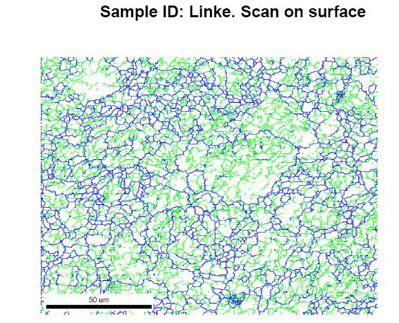
19 Plansee samples- Surface scans Larger grains compared to the sample marked'linke'

20

21 Strained Lattice
22 XRD study XRD spectra were recorded for the Pristine and Annealed Tungsten samples irradiated with 80 MeV and 100 KeV and compared with the Pristine and annealed ( 900 C and 1100 C ) samples. The changes in the Relative Peak Intensity, Peak Width and peak positions are attributed to Crystallographic Texture, Micro-strain and Macro-strian respectively.
23 1 1 0
24
25
26
27
28
29
30 Irradiation reduces the lattice stress Sample 2*theta theta delta d (Å) a (Å) strain(std) Stress (GPa) W110_S W110_A E W110_A E W110_A E Young s modulus 400 GPa for polycrystalline W at 20 C (Ref:Tungsten, Lassner & Schubert)
31
32 900 C Au 100 kev Au 80 MeV Crystallite Size 96 ± 0.31x nm Not determinable 142 ± 0.36x nm Micro strain η ~ ± 0.48x
33 900 C 1100 C Crystallite Size 96 ± 0.31x nm Not determinable Micro strain η ~ 0 -
34 PALS characterization
35 Details of Au and W irradiated samples and PALS characterization Sr. No. Identification (Sample details) Ion species Energy Fluence 1. 80MPWAu6p214 Au7+(197) 80 MeV 6.2x KPWAu117 Au MeV 1x MAWW114 W7+ (184) 80 MeV 1x MAWAu6p214 Au7+ (197) 80 MeV 6.2x MAWAu114 Au7+ (197) 80 MeV 1x KAWAu117 Au MeV 1x10 17

36
37 Effect of annealing in positron life time Enhanced mono-vacancy like defects and vacancy clustering Effect of stress in positron life time The life-time of perfect crystal W ~105 ps Pristine sample ~117 ps, much lower than mono-vacancy life time (also reported by Shengyun et.al, JNM, 343 (2005) 330) Could be an indication of stress in the lattice (also seen in XRD measurements) Stress can give intermediate life times First life time component (τ 1 ) for pristine and annealed samples along with respective intensities Annealing shows mono-vacancy like defects (τ 1 ) ~140 ps (higher intensity compared to pristine) Annealing increases (τ 2 ) from 280 ps to 384 ps Larger vacancy clusters Lower intensity of (τ 2 ) decomposition of vacancy clusters into mono-vacancy like defects Effect of stress relieving? Second life time component (τ 2 ) for pristine and annealed samples and their intensities

38 Effect of irradiation reduction in mono vacancy formation Stress/dislocation effects τ2 is reduced from 384 ps to ~300 ps due to ion bombardment independent of the ion energy. Also radiation induced stresses and dislocations in the lattice can give rise to intermediate positron life times (Kuramoto etal, JAERI conf ) Further investigations are ongoing to confirm this. The first lifetime is nearly same (~140 ps) for all irradiated samples. Although the irradiation dose (1x10¹⁴ and 6.2x10¹⁴) shows a slight variation, they are still within the experimental errors The intensity of the mono-vacancy like defects reduces due to irradiation 80 MeV irradiation in pristine sample also seem to have relieved the stress in positron range
39 Detail of 7.5 MeV W and 50 MeV H 2 irradiation of Tungsten Sample Sample ID W implantation fluence (ions /cm 2 ) Damage due to W ion implantation at surface(peak) (dpa) Hydrogen concentration (ions/cm 2 ) Damage due to H ion implantat. at surface(peak) (dpa) Plansee P1 mask (0.74) Plansee P (17) (0.74) Linke L (17) (0.74) Plansee P (1.7 ) (0.74) Linke L (1.7) (0.74) The displacement damage on the sample due to tungsten and hydrogen implantations as given in the Figures have been calculated using SRIM program using quick damage routines; The quick damage routine invokes the Kinchin Pease model where the number of displacements ND = 0.8 Edamage/ 2 Ed Where ND = total number of displacements Edamage = fraction of energy used in creating displacement damage Ed = displacement energy of 90 ev. We have calculated the fluence such that L1 and P1 samples are exposed to 10 dpa at the surface; Whereas the samples L2 and P2 are exposed to 1 dpa at the surface.

40
41 Fraction of hydrogen P P1 mask L P2 L Depth The hydrogen depth profiles obtained using SIMNRA program.
42
43
44

45

46

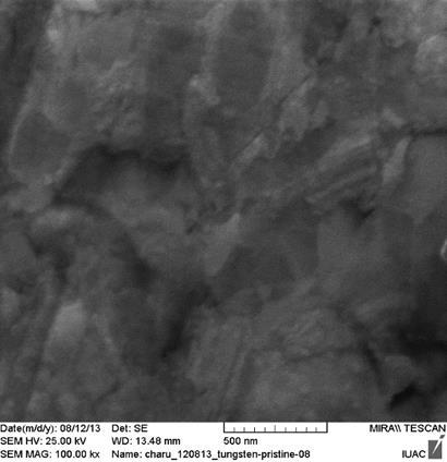
47 80MPWAu6p214 Image 2

48


49

50

51
52 Summary EBSD results show that Tungsten (Linke-Plansee) samples have equiaxed grains on the surface. However, in the cross section columnar grains are seen. In the Plansee samples there are larger grains and lattice is strained. The pristine and 900 C annealed samples are tensile strained with respect to standard relaxed tungsten matrix d values. It gets progressively relieved with 1100 C anneal, 100 kev irradiation and 80 MeV irradiation. All irradiated samples show that irradiation tends to increase preferred orientation in (200) and (211) direction, and the effect must be in substantial thickness of 10s of microns. Increase in the crystallite size is observed in 80 MeV irradiated gold. PALS results show the effect of annealing in terms of enhanced monovacancy like defects and vacancy clustering. The effect of irradiation is seen in the reduction in mono vacancies. ERDA results show that as the W irradiation dpa value incresaes, small increase in the H trapping is seen. Nanostructuring is observed in 80 MeV Au irradiated Tungsten.
53 Thank You