Development of Nano-Structured Solid Oxide Fuel Cell Electrodes
|
|
|
- Gervais Hicks
- 5 years ago
- Views:
Transcription
, Institute of Technical Thermodynamics, Pfaffenwaldring 38-48, D-70569 Stuttgart, Germany 17th Annual International")
1 Development of Nano-Structured Solid Oxide Fuel Cell Electrodes G. Schiller, S.A. Ansar, M. Müller German Aerospace Center (DLR), Institute of Technical Thermodynamics, Pfaffenwaldring 38-48, D Stuttgart, Germany 17th Annual International Conference on Composites/Nano Engineering (ICCE-17), Honolulu, July 26-31, 2009
2 Outline Introduction Principle of planar SOFC DLR spray concept for SOFC Nanostructured Cathode by using RF Plasma Technology (TPCVD) Deposition from liquid precursors Phase purity Structure Nanostructured Anode by using DC Plasma Technology Agglomerated nanoparticles Suspension plasma spraying (SPS) Solution precursor plasma spraying (SPPS) Conclusion
3 Design and Principle of a Planar SOFC Unconverted Air Bipolar Plate Air Reaction Products Cathode Electrolyte Anode Cathode + O 2 O 2 O 2 O 2 O 2 M Fuel Gas Load O 2- O 2-2- O2- O HO H - HO H H 2 2 A HO 2 Anode Solid Electrolyte E
4 SOFC Metal-Supported Cell Plasma Deposition Technology Thin-Film Cells Ferritic Substrates and Interconnects Compact Design with Thin Metal Sheet Substrates Brazing, Welding and Glass Seal as Joining and Sealing Technology oxygen/air not used air air channel fuel channel Bipolar plate protective coating contact layer cathode current collector cathode active layer electrolyte anode porous metallic substrate Bipolar plate fuel brazing not used fuel + H O 2 (not in scale) 30 m 25 m 35 m

5 Plasma Spray Laboratory at DLR Stuttgart

6 Experimental Setup Atomization Tasks: spray angle homogeneous spray (narrow droplet size distribution) precursor gas central gas shea th ga s 500 KHz generator ~ peristaltic pump liquid precursor atomizing gas injection probe z-adjustable RF plasma torch Problems: plasma small dimensions extremely high temperature Present solution: air assist atomizer : disintegration of liquid stream in gas jet x-y-mova ble substrate coating vacuum reactor window vacuum pump
7 Applied Precursor Solutions and Desired Synthesis Products A B C D E F Synthesis product Precursor Concentration La(NO 3 ) 3 6 H 2 O 0,9 M La 0.9 Sr 0.1 MnO 3 (LSM) Sr(NO 3 ) 2 0,1 M Mn(NO 3 ) 2 4 H 2 O 1,0 M La 0.5 Sr 0.5 MnO 3 (LSM) La 0.65 Sr 0.3 MnO 3 (ULSM) Pr 0.65 Sr 0.3 MnO 3 (UPSM) La 0.8 Sr 0.2 FeO 3 (LSF) La 0.8 Sr 0.2 (Co,Fe)O 3 (LSCF) G La 0.58 Sr 0.4 Fe 0.8 Co 0.2 O 3 (LSFC) H Pr 0.58 Sr 0.4 Fe 0.8 Co 0.2 O 3 (PSFC) La(NO 3 ) 3 6 H 2 O Sr(NO 3 ) 2 Mn(NO 3 ) 2 4 H 2 O La(NO 3 ) 3 6 H 2 O Sr(NO 3 ) 2 Mn(NO 3 ) 2 4 H 2 O Pr(NO 3 ) 3 5 H 2 O Sr(NO 3 ) 2 Mn(NO 3 ) 2 4 H 2 O La(NO 3 ) 3 6 H 2 O Sr(NO 3 ) 2 Fe(NO 3 ) 3 9 H 2 O La(NO 3 ) 3 6 H 2 O Sr(NO 3 ) 2 Co(NO 3 ) 2 6 H 2 O Fe(NO 3 ) 3 9 H 2 O La(NO 3 ) 3 6 H 2 O Sr(NO 3 ) 2 Fe(NO 3 ) 3 9 H 2 O Co(NO 3 ) 2 6 H 2 O Pr(NO 3 ) 3 5 H 2 O Sr(NO 3 ) 2 Fe(NO 3 ) 3 9 H 2 O Co(NO 3 ) 2 6 H 2 O 0,5 M 0,5 M 1,0 M 0,65 M 0,3 M 1,0 M 0,65 M 0,3 M 1,0 M 0,8 M 0,2 M 1,0 M 0,8 M 0,2 M 0,5 M 0,5 M 0,58 M 0,4 M 0,8 M 0,2 M 0,58 M 0,4 M 0,8 M 0,2 M
 LaMnO 3 La 2 O 3 Top: TPCVD coating from central part of plasma jet")
8 X-Ray Diffraction Patterns of La 0.9 Sr 0.1 MnO 3 LaMn perovskite Key parameter: Mn loss depends on radial distance from plasma jet axis Intensity (arbitrary units) LaMnO 3 La 2 O 3 Top: TPCVD coating from central part of plasma jet Bottom: TPCVD coating from cooler margin Intensity (arbitrary units) Theta LaMnO 3 La 2 O 3 stationary substrate Theta
9 X-Ray Diffraction Patterns of Pr 0.58 Sr 0.4 Fe 0.8 Co 0.2 O 3 Top: TPCVD coating from central part of plasma jet Bottom: TPCVD coating from cooler margin stationary substrate
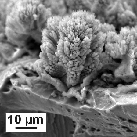
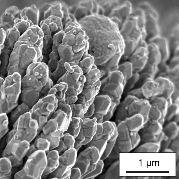
10 Microstructure of TPCVD Perovskite Coatings


11 Functional Principle of DC Plasma Plasma Gases Ar H 2 N 2 He Plasma Gun Particle Melting and Acceleration Powder Jet Coating Substrate Particle Injection Particle Impingement Splat Layering

12 Vacuum Plasma Spraying of SOFC Cells


13 Feedstock Powder for DC Plasma Spraying NiO+YSZ Powder Co-precipitation and Spray-Drying 22 vol%nio + YSZ Agglomerated Agglomerate size: µm Primary particle size: nm
14 As-Sprayed Anode Structure and XRD Powder Deposit Z Z N N Fe Z Z N N= Ni(II)O Z= Cubic-zirconia theta ( ) 2 µm NiO+YSZ Plasma Sprayed Deposit Z Powder Deposit N Particle size in deposit was nm compared to nm for the feedstock powder Z Ni(II)O and cubic-ysz were the phases detected by XRD theta ( )
15 Permeability of Anode Permeability Coeff. (10-14 m²) AS Reduced AS Reduced Conven. NiO+YSZ Nano NiO+YSZ
16 Conductivity of Nano-Anode Cond (1/ohm.cm) σ (Ω/cm) σ Cond (Ω/cm) (1/ohm. cm) Conventional Anode Nano Anode Time (h) Time (h) Test Atmosphere 2 slm Ar+5 vol% H 2 Conductivity of nano and conventional anode were comparable for first 30 to 40 hrs Conductivity of nano anode increased for extended period of test time - possible cause could be Ni particles phase I sintering
17 Electrochemical Testing V V Cell voltage U [V] Power density p [mw/cm²] Current density i [ma/cm²] 0 Reference cell with conventional anode ( ); Cell with nanostructured anode after 100 h (Δ) and after 1500 h ( ) of operation 800 C - Cell area 12.6 cm² - Gases: 0.5 slm H slm N 2 /2.0 slm air). Cells containing a nano anode show 34% higher power density Anodic polarization at OCV of nano anode was 0.42 Ωcm² instead of 0.72 Ωcm² for conventional anode 3.33%/kh degradation rate for cells with nano anode is comparable to cells having conventional anodes No evidence of additional degradation due to nanomaterials
18 Nano Anode Structure after SOFC Operation 2 µm 2 µm After 100 h of operation After 1500 h of operation Limited grain growth and sintering Particle size: 60 to 220 nm after 100 h and 95 to 390 nm after 1500 h Expected mechanisms are phase I or gas-phase sintering

19 Suspension and Solution Precursor Plasma Spraying Suspension Plasma Spraying Injection of nano-particles in plasma by suspending them in a liquid. Solution Precursor Plasma Spraying In-flight nano-particles synthesis by chemical reaction of metal salt precursors in plasma.


20 Suspension Plasma Spraying YSZ 40 nm particles and development of stable suspension using Zeta potential Development of stable suspensions zeta-potential [mv] Dispersant [wt.%] Nanostructured porous YSZ deposit Porosity 35% Outlook: Additon of NiO for anode and LSM for cathode
21 Conclusion Nanostructured cathodes and anodes for SOFC were prepared by applying plasma deposition processes (RF and DC plasma) Two approaches were applied: - Introduction of pre-synthesized nanoparticles as agglomerates or suspensions into the plasma - In-situ synthesis of nanomaterials and deposits from solutions of metal salts TPCVD cathodes initially exhibited undesired secondary phases which was overcome by adjusting the chemical composition of the precursor material. The microstructure was columnar type with very high open porosity For 1500 hours of operation only limited growth of nanosized particles was observed in SOFC anodes Further improvement of the microstructure of anodes is in progress using DC plasma suspension and solution precursor plasma spraying
22
23 Synthesis from Liquid Precursors in an RF Plasma Why r.f. plasma? large volume, low jet velocity, i.e. more complete synthesis axial material injection electrodeless, i.e. oxidizing conditions possible Why liquid precursors? cost reduction continuous feeding of material central gas sheath gas gas distributor induction coil precursors and atomization gas injection probe quartz glas tube ceramic tube polymer body flange exit nozzle homogeneous distribution in the plasma synthesis of thermally instable materials simple adjustment of stoichiometry
24 X-Ray Diffraction Patterns of La 0.58 Sr 0.4 Fe 0.8 Co 0.2 O LSFC auf Cr5Fe, TPCVD, zentrum, HF0224 [48-124] La0.6 Sr0.4 Co0.8 Fe0.2 O3 / Cobalt Strontium Iron Lanthanum O [5-602] La2 O3 / Lanthanum Oxid Absolute Intensity Top: TPCVD coating from central part of plasma jet Theta Bottom: TPCVD coating from cooler margin LSFC auf Cr5Fe, TPCVD, Rand, HF0224 [48-124] La0.6 Sr0.4 Co0.8 Fe0.2 O3 / Cobalt Strontium Iron Lanthanum O [34-396] Fe - Cr / Iron Chromium stationary substrate Absolute Intensity Theta
 R U I I = 10 ma el l R A S cm 100 l 0 0 10 20 30 40 50 60 Operation Time / h ΔV")
25 Electrical Conductivity Measurement Temperature / C Temperature Atmosphere: Purge gas (Ar / 5vol% H 2 ) R U I I = 10 ma el l R A S cm 100 l Operation Time / h ΔV

26 Electrochemical Testing of Full Cells Operating temperature Effective area Gas volume flow anode cathode 800 C cm slpm H slpm N 2 2,0 slpm Air Air 1 SOFC 2 Gold sealing 3 Platinum net 4 Glass sealing 5 Housing 6 Weight H 2 + N 2