NRC Publications Archive Archives des publications du CNRC
|
|
|
- Lora Rich
- 5 years ago
- Views:
Transcription
1 NRC Publications Archive Archives des publications du CNRC Modeling warpage and shrinkage in thermoplastic blow molded part using BlowView Benrabah, Z.; Bardetti, A.; Ward, G. NRC Publications Record / Notice d'archives des publications de CNRC: Access and use of this website and the material on it are subject to the Terms and Conditions set forth at READ THESE TERMS AND CONDITIONS CAREFULLY BEFORE USING THIS WEBSITE. L accès à ce site Web et l utilisation de son contenu sont assujettis aux conditions présentées dans le site LISEZ CES CONDITIONS ATTENTIVEMENT AVANT D UTILISER CE SITE WEB. Questions? Contact the NRC Publications Archive team at PublicationsArchive-ArchivesPublications@nrc-cnrc.gc.ca. If you wish to the authors directly, please see the first page of the publication for their contact information. Vous avez des questions? Nous pouvons vous aider. Pour communiquer directement avec un auteur, consultez la première page de la revue dans laquelle son article a été publié afin de trouver ses coordonnées. Si vous n arrivez pas à les repérer, communiquez avec nous à PublicationsArchive-ArchivesPublications@nrc-cnrc.gc.ca.


2 Modeling Warpage and Shrinkage in a Thermoplastic Blow Molded Part using BlowView NRC: AIP: Zohir Benrabah and Anna Bardetti Geoff Ward 33rd Annual Blow Molding Conference October 2-4, 2017 Chicago, IL, USA
3 Overview Who are we? - NRC - SIGBLOW consortium - BlowView Software Objectives of warpage model development Understanding shrinkage and warpage in blow molding applications Assessing the current cooling/warpage numerical tool available in BlowView based on a case study from Agri-Industrial Plastics (AIP) Validation and comparison with experimental results Conclusion and future work 2

4 NRC SIGBLOW/SIGFORM/SIGSuBM: Industrial R&D Groups Established in 1992 Blow molding simulation research consortium, led by NRC: Development of in-house engineering software (BlowView) dedicated to simulate Polymer Forming Processes Small membership base - select group of OEMs, Automotive, resin manufacturers, packaging and suppliers, such as: o Ford Motor Company o Kautex Textron o Plastic Omnium o TI Automotive o ABC Group o The Coca-Cola Company o AMCOR o Graham Packaging o Agri-Industrial Plastics o Silgan Plastics o Plasticade o DSM o YAPP o Walbro o Consolidated Container Company o Conti-Tech o Trinseo Meet semi-annually Members provide input to govern software development (New functionalities, capabilities) 3


5 NRC BlowView software capabilities Extrusion Blow Molding (EBM) Stretch Blow Molding (SBM) Twin Sheet Extrusion Blow Molding (TSEBM) Thermoforming Suction Blow Molding (SuBM) Form 3D 4
6 Objectives of Warpage Model Development Background The shrinkage and warpage have been a big concern in the blow molding applications. For PFT in particular, poor dimensional stability due to warpage and shrinkage causes problems in: Assembling the fuel tank components (tolerance issue) Improper location and/or fitting of components (i.e. fuel line inside tank groove) Increase tank strap tension/stress Increase strap bolt force Increase tank shell stress Decrease plastic welds quality/strength Erratic fuel volume level indication issues, due to Changes in float location and/or orientation 5
7 Objectives of Warpage Model Development Background KAUTEX-TEXTRON/FORD MOTOR/NRC (2013) Usman M., Ahmad S., Benrabah Z., Atsbha H., A Plastic Fuel Tank Deformation in the Post Blow Molding Phase due to Material Shrinkage/ Warpage. SPE: Annual Blow Molding Conference, 8-9th October 2013, Atlanta. GA, USA P.O/FORD MOTOR/NRC (2016) Usman M., Ahmad S., Siddiqui S., Benrabah Z., Bardetti A., Mir H., Lempicki J., Kulevski J., Masse H, Plastic Fuel Tank Deformation in the Post Blow Molding Phase: Warpage and Shrinkage Tolerance Issue. SPE: Annual Blow Molding Conference, 3-5th October 2016, Atlanta. GA, USA 6

8 Objectives of Warpage Model Development ACTIONS Since tolerance issue due to warpage deformation is decisive quality criterion for part acceptance, an increasing attention is paid to part warpage in the early stages of product design. Therefore, part warpage and tolerance issues need to be controlled and optimized using an accurate and suitable prediction tool using BLOWVIEW software 1. Benrabah Z., Mir H., Lempicki J., Bardetti A., Ahmad S., Siddiqui S., Usman M., Contribution to Warpage Analysis Using BlowView Software, 74th Annual technical conference of the Society of Plastics Engineers (ANTEC 2016); the plastics conference, 23rd-25th May 2016, Indianapolis, IN, USA 2. Benrabah, Z., MIR, H., Zhang, Y., 2013: Thermo-Viscoelastic Model for Shrinkage and Warpage Prediction during Cooling and Solidification of Automotive Blow Molded Parts. SAE International Journal of Materials and Manufacturing, Volume 6, Issue 2, pp Z. Benrabah Z., P. Debergue, R. DiRaddo, Deflashing of Automotive Formed Parts: Warpage and Tolerance Issues. SAE 2006 Transactions Journal of Materials and manufacturing, Mechanical System: p 4.P. Debergue, H. Massé, Thibault F., Diraddo, Modelling of Solidification Deformation in Automotive Formed Part, SAE Transactions Journal of Materials and manufacturing, Mechanical System: 112(5),
9 Understanding Shrinkage and Warpage in Blow Molding Warpage Causes? Why does it occur Process-induced Residual Stresses are the main cause of part warpage Thermal-Induced Residual Stresses: - Differential shrinkage - Inhomogeneous cooling conditions - Uneven Part Temperature (across the thickness and over the part) - Uneven Part Thickness (~ 3 10 mm) - Inhomogeneous materials across the part thickness (up to 6-7 layers with varying properties) Flow-Induced Residual Stresses : - Extrusion rate - Shear rate - Material viscosity - Shear & normal stresses - Melt temperature, Head pressure 8
10 Process prediction in BlowView : From Extrusion to Warpage Prediction Process prediction in BlowView: Extrusion Pre-Blow Inflation Cooling in the Mold Cooling after Ejection: - Air - In Shell Cooling - Underwater - Others. Extrusion and Blow Molding stages In mold/out of mold cooling 9


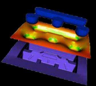
11 Warpage Prediction Model in BlowView Warpage analysis performed on the Part CAD vs the inflated parison Mesh at the end of inflation Thickness Temperature Contact, Stress Part CAD Mesh 10

12 General Information Material: Marlex HXM Total Mass Flow: 3733 Kg/hr Extrusion Time: 7.0 sec Cooling In-Mold: 180 sec Total Shot Weight: Tank Weight : Flash Weight: 6.9 Kg 3.6 Kg 3.3 Kg 11


13 Material Data Warpage Model Linear Expansion Coefficients 12

14 Results - Parison Extrusion and Pre-Blow End of Extrusion End of Pre-Blow 13

15 Results - End of Inflation Lower Shell Upper Shell 14
16 Thickness Comparison with Measured Data Measured data provided by AIP Predicted BlowView Simulation (15 % Shrinkage applied) Measured data provided by AIP Predicted BlowView Simulation (15 % Shrinkage applied) 15


17 Warpage Simulation Two warpage simulations were considered: Warpage on Inflated Parison Warpage on Part CAD Warpage on Inflated Parison Warpage on CAD Part 16
 Warpage")

18 Warpage Results Warpage Prediction on Inflated Parison (with flash) Warpage Prediction on Part CAD 17 Note: NormU is the total magnitude of the displacement in mm

19 Warpage on part CAD Results Average Temperature at end of Cooling-in-Mold Warpage Prediction 18
 Distance (mm) 19 Note: Distance is the normal magnitude of the displacement between meshes")
20 Warpage on part CAD Results vs Experimental Difference between simulated warped Part CAD and initial Part CAD (Simulation) Distance (mm) Difference between engineered scan of actual part and initial Part CAD (Experiment) Distance (mm) 19 Note: Distance is the normal magnitude of the displacement between meshes


 Measured")

21 Thickness Comparison with Measured Data Measured data provided by AIP Predicted BlowView Simulation (15 % Shrinkage applied) Measured data provided by AIP Predicted BlowView Simulation (15 % Shrinkage applied) 20


22 Error between Warpage Simulation and Actual Part Scan Lower Shell Upper Shell Left Side Right Side Error Distance (mm) Average Error: 2.05 mm and STD : 1.76 mm 21 Note: Error Distance is the normal magnitude of the displacement between meshes


23 Error between Warpage Simulation and Actual Part Scan Upper Shell Lower Shell 22


24 Error between Warpage Simulation (on inflated parison) and Actual Part Scan Lower Shell Upper Shell Left Side Right Side Error Distance (mm) Average Error: 3.53 mm and STD : mm 23
25 Conclusion and Future Work This work was intended to validate the warpage prediction using BlowView for an industrial part provided by Agri-Industrial Plastics The predicted thickness are in good agreement with the measured data provided by AIP Two warpage simulations were considered: - The results show that the Warpage on CAD Part improves the warpage prediction, due to better mesh quality - The predicted warpage results are in relatively good agreement with the measured data provided by AIP Take into account a cooling channel in the mold Sensitive analysis on material properties (i.e., L.E.C, HTC, etc...) 24