Chapter 11. Measurement of Temparature. Oxford University Press All rights reserved.
|
|
|
- Mae Curtis
- 5 years ago
- Views:
Transcription
1 Chapter 11 Measurement of Temparature

2 Introduction Temperature can be defined as a condition of a body by virtue of which heat is transferred from one system to another. A comparison between Kelvin, Celsius, and Fahrenheit scales with respect to absolute zero, and boiling and freezing points of water is shown in Table The scales used to measure temperature can be divided into relative scales [Fahrenheit ( F) and Celsius ( C)] and absolute scales [Rankine ( R) and Kelvin (K)]. The various temperature scales are related as follows: F = 1.8C + 32 C=(F 32)/1.8 R = F K = C + 273
3 Methods of Measuring Temperature can be sensed using many devices, which can broadly be classified into two categories: contact and non contact type sensors. In case of contact type sensors, the object whose temperature is to be measured remains in contact with the sensor. Inference is then drawn on the assessment of temperature either by knowing or by assuming that the object and the sensor are in thermal equilibrium. Contact type sensors are classified as follows: 1. Thermocouples 2. Resistance Temperature Detectors (RTDs) 3. Thermistors 4. Liquid in glass thermometers 5. Pressure thermometers 6. Bimetallic strip thermometer
4 Methods of Measuring In case of non contact type sensors, the radiant power of the infrared or optical radiation received by the object or system is measured. Temperature is determined using instruments such as radiation or optical pyrometers. Non contact type sensors are categorized as follows: Radiation pyrometers Optical pyrometers Fibre optic thermometers
 is at a")
5 Thermocouples Thermocouples are active sensors employed for the measurement of temperature. The thermoelectric effect is the direct conversion of temperature differences to an electric voltage. In 1821, Thomas Johan Seebeck discovered that when two dissimilar metals are joined together to form two junctions such that one junction (known as the hot junction or the measured junction) is at a higher temperature than the other junction (known as the cold junction or the reference junction), a net emf is generated. This emf, which also establishes the flow of current, can be measured using an instrument connected as shown in Fig
6 Thermocouples The magnitude of emf generated is a function of the junction temperature. It is also dependent on the materials used to form the two junctions. The thermoelectric emf is a result of the combination of two different effects the Peltier effect and the Thomson effect. The French physicist Jean Charles Athanase Peltier discovered that if two dissimilar metals are connected to an external circuit in a way such that a current is drawn, the emf may be slightly altered owing to a phenomenon called Peltier effect. A potential difference always exists between two dissimilar metals in contact with each other. This is known as the Peltier effect.
7 Thermocouples The Thomson effect states that even in a single metal a potential gradient exists, provided there is a temperature gradient. Both these effects form the basis of a thermocouple, which finds application in temperature measurement. The flow of current through the circuit is spontaneous when two dissimilar metals are joined together to form a closed circuit, that is, a thermocouple, provided one junction is maintained at a temperature different from the other. This effect is termed the Seebeck effect.
8 Thermocouples Laws of Thermocouples Apart from the Peltier and Thomson effects, which form the basis of thermoelectric emf generation, three laws of thermocouples that govern this phenomenon are required to be studied in order to understand their theory and applicability. Law of Homogeneous Circuit This law states that a thermoelectric current cannot be sustained in a circuit of a single homogenous material, regardless of the variation in its cross section and by the application of heat alone. This law suggests that two dissimilar materials are required for the formation of any thermocouple circuit.
9 Thermocouples Law of Intermediate Metals If an intermediate metal is inserted into a thermocouple circuit at any point, the net emf will not be affected provided the two junctions introduced by the third metal are at identical temperatures. This law allows the measurement of the thermoelectric emf by introducing a device into the circuit at any point without affecting the net emf, provided that additional junctions introduced are all at the same temperature.

10 Thermocouples It is clear from Fig that when a third metal, M3, is introduced into the system, two more junctions, R and S, are formed. If these two additional junctions are maintained at the same temperature, say T3, the net emf of the thermocouple circuit remains unaltered.
11 Thermocouples Law of Intermediate Temperatures If a thermocouple circuit generates an emf e 1 when its two junctions are at temperatures T 1 and T 2, and e 2 when the two junctions are at temperatures T 2 and T 3, then the thermocouple will generate an emf of e1 + e 2 when its junction temperatures are maintained at T 1 andt 3 (Fig. 15.3). This law pertains to the calibration of the thermocouple and is important for providing reference junction compensation.

12 Thermocouples This law allows us to make corrections to the thermocouple readings when the reference junction temperature is different from the temperature at which the thermocouple was calibrated.

13 Thermocouple Materials Theoretically, any two different materials can be used to form a thermocouple. However, only a few are suitable for temperature measurement applications. Combinations of different thermocouple materials and their temperature range are given in Table 15.2.
14 Advantages of Thermocouples The following are some distinct advantages that merit the use of thermocouples: Temperature can be measured over a wide range. Thermocouples are self powered and do not require any auxiliary power source. A quick and good response can be obtained. The readings obtained are consistent and hence are consistently repeatable. Thermocouples are rugged, and can be employed in harsh and corrosive conditions. They are inexpensive. They can be installed easily.
15 Disadvantages of Thermocouples Thermocouples also have certain disadvantages, which are listed as follows: They have low sensitivity when compared to other temperature measuring devices such as thermistors and RTDs. Calibration is required because of the presence of some nonlinearity. Temperature measurement may be inaccurate due to changes in the reference junction temperature; hence thermocouples cannot be employed for precise measurements. For enhancing the life of thermocouples, they should be protected against contamination and have to be chemically inert.

16 Thermopiles An extension of thermocouples is known as a thermopile. A thermopile comprises a number of thermocouples connected in series, wherein the hot junctions are arranged side by side or in a star formation. In such cases, the total output is given by the sum of individual emfs.
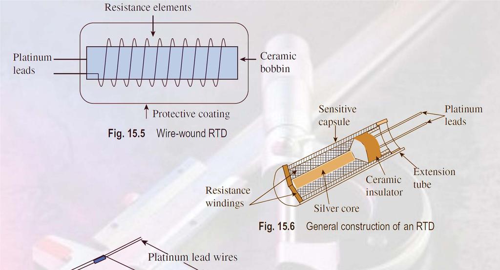
17 Resistance Temperature Detectors RTDs are also known as resistance thermometers. The American Society for Testing and Materials has defined the term resistance thermometer as follows: RTD is a temperature measuring device composed of a resistance thermometer element, internal connecting wires, a protective shell with or without means for mounting a connection head, or connecting wire or other fittings, or both. When platinum is employed in RTD elements, they are sometimes termed platinum resistance thermometers The general construction of a resistance thermometer is shown in Fig Figure 15.7 shows a thin film RTD.
18 Resistance Temperature Detectors RTDs essentially have the following three configurations: 1. A partially supported wound element 2. Wire wound RTD: Prepared by winding a platinum or metal wire on a glass or ceramic bobbin and sealed with a coating on molten glass known as wire wound RTD elements Fig Thin film RTD: Prepared by depositing or screening a platinum or metal glass slurry film onto a small flat ceramic substrate called thin film RTD elements

19
20 Thermistors Semiconductors that are used to measure temperature are called thermistors. When a thermistor is employed for temperature measurement, its resistance decreases with increase in temperature. Materials used in thermistors for temperature measurements have very high temperature coefficients (8 10 times higher than platinum and copper) and high resistivity (higher than any pure metal). Figure 15.8 illustrates the different forms in which thermistors can be made. A variety of ceramic semiconductor materials qualify as thermistor materials. Among them, germanium containing precise proportions of arsenic, gallium, or antimony is most preferred. Thermistors are also produced using oxides of manganese, nickel cobalt, nickel copper, iron, zinc, titanium, and tin.

21 Liquid in Glass Thermometer The liquid in glass thermometer is the most popular and is widely used for temperature measurement. It comprises a bulb that contains a temperaturesensing liquid, preferably mercury. A graduated capillary tube is connected to the bulb. At the top of the capillary, a safety or expansion bulb is provided. Figure shows a liquid in glass thermometer. Liquid in glass thermometers are simple, portable, and inexpensive. However, they are fragile and not suitable for remote applications and sensing surface temperature.
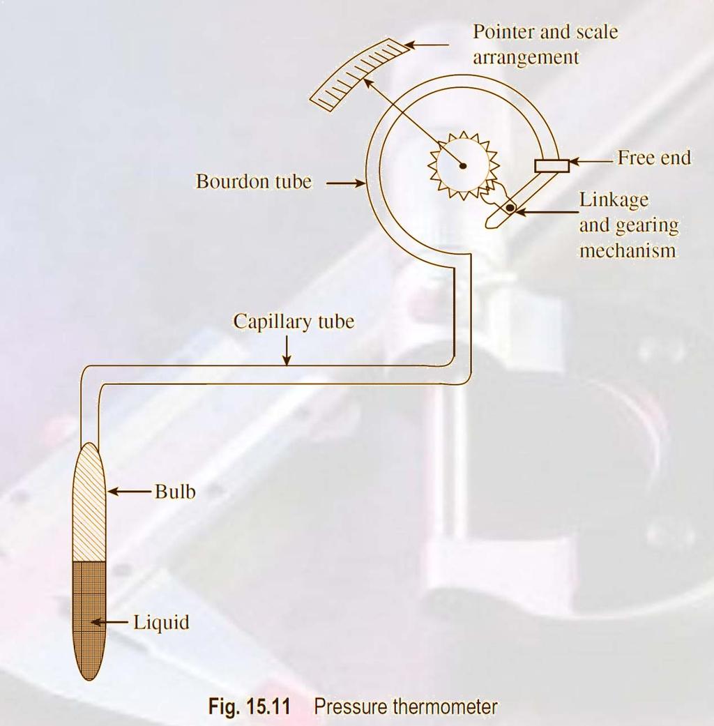
22 Pressure Thermometer The change in temperature can be measured using pressure thermometers. These thermometers work on the principle of thermal expansion of the matter wherein the change in temperature is to be measured. Temperature change can be determined using these thermometers, which rely on pressure measurement. Pressure thermometers comprise the following components: a bulb filled with a liquid, vapor, or gas; a flexible capillary tube; and a bourdon tube. Due to variation in temperature, the pressure and volume of the system change and the fluid either expands or contracts. This causes the bourdon tube to move or uncoil, which actuates the needle on the scale, thus providing a measure of the temperature.
23
24 Bimetallic Strip Thermometer A bimetallic strip thermometer works on the well known principle that different metals expand and contract to different degrees, depending on the coefficient of expansion of the individual metals. For example, if two strips of two different metals (steel and copper) are firmly welded, riveted, or brazed together and subjected to temperature changes, either cooling or heating, the degree of contraction or expansion of the metals differ depending on their coefficient of expansion. The metal strips tend to bend owing to their different coefficients of expansion; the contraction or expansion of one strip will be greater than that of the other. The difference in the expansion of two metals, which makes the strip bend, is a measure of temperature, and since two different metal strips are employed it is called a bimetallic strip thermometer. Figure shows the principle of a bimetallic strip.

25 Bimetallic Strip Thermometer
26 Pyrometry If the temperature of a very hot body has to be measured, contact type temperature measuring devices will not be suitable, because they are liable to be damaged when they come in contact with the hot body. Hence, the use of non contact type temperature measuring devices becomes imperative. When such devices are employed for high temperature measurement, the distance between the source of the temperature and the instrument has no effect on the measurement. These non contact type devices are called pyrometers. The term pyrometer is of Greek origin, wherein pyro stands for fire and metron means to measure. Measurements of temperature are carried out either by measuring energy radiated by a hot body or by colour comparison. Pyrometers are classified into two distinct categories: total radiation pyrometers and optical pyrometers.
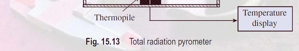
27 Total Radiation Pyrometer A total radiation pyrometer gives a measure of temperature by evaluating the heat radiation emitted by a body. All the radiations emitted by a hot body or furnace are measured and calibrated for black body conditions. A total radiation pyrometer (shown in Fig ) basically comprises an optical system that includes a lens, a mirror, and an adjustable eyepiece. The heat energy emitted from the hot body is focused by an optical system onto the detector. The heat energy sensed by the detector, which may be a thermocouple or a thermopile, is converted to its analogous electrical signal and can be read on a temperature display device.

28 Total Radiation Pyrometer
29 Optical Pyrometer Optical pyrometers work on the disappearing filament principle. In order to measure temperature, the brightness generated by the radiation of the unknown source or hot body whose temperature is to be determined is compared with that of the reference lamp. The brightness of the reference lamp can be adjusted so that its intensity is equal to the brightness of the hot body under consideration. The light intensity of the object depends on its temperature, irrespective of its wavelength. A battery supplies the current required for heating the filament. The current flowing through the filament is adjusted by means of a rheostat and an ammeter is used to measure it. The current passing through the circuit is proportional to the temperature of the unknown source. An optical pyrometer is schematically represented in Fig

30 Optical Pyrometer
31 Fibre optic Pyrometer At the tip of the fibre optics free end, a temperature sensing component is placed. The desired radiation is collected by connecting a measuring system to the other end. The information collected is then processed into a temperature value. The fibre optic pyrometer essentially comprises a fibreoptic cable and an array of components such as probes, sensors or receivers, terminals, lenses, couplers, and connectors. A fibre optic cable is used to transmit radiation from the black box cavity to a spectrometric device that computes the temperature.
32 Fibre optic Pyrometer The operating temperature of the fibre optics can be raised as they do not possess any electronic components and hence do not require any cooling effort. Fibre optics can be used up to a temperature of 300 C and are available for wavelengths of 1 and 1.6 μm. These find applications in procedures such as induction heating and welding. Fibre optic pyrometers are basically employed in applications where strong electrical and magnetic interference fields act. Oxford University Press All rights reserved.
33 Infrared Thermometer It is a well known fact that every material or matter whose temperature is above absolute zero emits infrared radiations depending on the temperature. Infrared radiations are invisible to the human eye and can be sensed as heat. An infrared thermometer is a non contact type sensor that can detect infrared radiation from a heated body. We know that the radiation emitted by an object or a heated body has different wavelengths. Radiations that have longer wavelengths than visible light are known as infrared radiations; these radiations possess less energy and are less harmful. A part of the infrared energy radiated by an object is detected by an infrared sensor. It essentially measures the amount of radiation emitted by an object. Infrared thermometers are ideally suited for high temperature measurement. An infrared thermometer comprises a lens through which the infrared wave is focused on the detector.

34 The infrared energy is absorbed and converted into an electrical signal by the detector. The amount of radiation striking the detector determines the electrical output signal. The amplified electrical output signal is then displayed on the screen in terms of temperature units. Variation due to ambient temperature is adequately compensated before display. The principle of infrared measurement is schematically represented in Fig An infrared thermometer facilitates the measurement of temperatures of moving objects.