University of Illinois Update
|
|
|
- Gerald Davidson
- 5 years ago
- Views:
Transcription
1 University of Illinois Update Pooled Fund - LTC TAP Meeting October 5, 2011 Northland Inn, Minneapolis, MN William G. Buttlar, Glaucio Paulino, Eshan Dave, Sofie Leon, Nathan Kebede, Steven Gresk 10/5/2011 Department of Civil & Environmental Engineering University of Illinois at Urbana-Champaign
 All specimens were 50mm thick disks, 81 lab compacted and 2 from field")
2 Specimens Received July 27, specimens received (3 replicates at each test temperature) All specimens were 50mm thick disks, 81 lab compacted and 2 from field cores
3 Wisconsin samples (mostly retests) All samples have PGLT of C 4% air voids gyratory compacted 7% air voids gyratory compacted 7% air void and oven conditioned Field core Oven conditioned samples and field core tested at PGLT All others tested at PGLT and PGLT+10
4 Validation Testing (Task 6) Marathon (PG58-28) 12.5mm and19mm CITGO (PG58-28) 12.5mm and 19mm VALERO (PG58-28) 12.5mm and 19mm Warm mix (PG58-28) Reinke s warm mix w/ RAP and antistrip MIF RAP (PG58-34) 12.5mm and 19mm MIF Virgin (PG58-34) 12.5mm and 19mm TEST TEMPERATURE IS PGLT AND PGLT+10 (All tests to be completed by 10/31/11) Olmsted Co: *Rd104 **Rd112


5 Fabrication Notching and face cuts Coring of loading holes

6 Testing Geometry Instron 8500 servo-hydraulic load frame with an environmental chamber capable of controlling the temperature from 30 o C to -30 o C
7 Fracture energy of Wisconsin mix, J/m 2 average CMOD Fracture Energy@-22C average CMOD Fracture CoV=11.5% CoV=9.5% CoV=8.9% CoV=31.7% CoV=10.1% CoV=11.1% wis-4% wis-7% wis-c-7% wis-field *C-oven conditioned
8 Fracture Energy (J/m^2) Influence of Aging on Mixture Fracture Energy Field Aging Fracture Energy Aging Time (hr) 12.5mm NMAS PG58-28 Unmodified Mixture Demonstrates that Fracture Energy can First Increase, then Decrease with Aging. However, Creep Compliance Simply Decreases with Aging. (AAPT, Braham et al., 2009) 8
9 38mm Creep Compliance from DC(T) IDT Epsilon gages x CMOD Epsilon Gage Apply a tensile creep load and collect deflections Creep load should be high enough to induce measurable deflection but it should not create damage at notch tip x is optimized using experimental and modeling correlation Results will be compared to IDT Creep compliance


10 DC(T) + IDT Old model New model 10
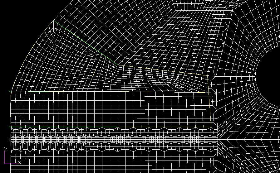
 - DCT specimen without notch(viscoelastic) x - 9 Nodesets along the X axis: X (mm): 2, 10, 20, 30, 40, 50, 60, 70,")
11 DCT+IDT model - Four Different FEM Models : - DCT specimen with notch(elastic) - DCT specimen with notch(viscoelastic) - DCT specimen without notch(elastic) - DCT specimen without notch(viscoelastic) x - 9 Nodesets along the X axis: X (mm): 2, 10, 20, 30, 40, 50, 60, 70, 80 11
12 Update on Low Temperature Cracking Model for Asphalt Concrete ILLI-TC Department of Civil & Environmental Engineering University of Illinois at Urbana-Champaign
13 Why do we Need a Thermal Cracking Model? Binder important, but does not completely control: Aggregate/mastic effects on mixture creep/fracture properties Effects of RAP, WMA, fibers, and other additives Final, constructed mixture volumetrics voids, agg structure Plant/field aging Structural effects of temperature profile, fracture process Modeling can provide: True performance prediction (cracking vs. time) Input for maintenance decisions Insight for policy decisions 10/7/2011 Low Temperature Cracking 13
")
 Change in stress intensity factor Fracture parameters Change")

14 Old TC Model vs. New TC Model TC Model K Stress Intensity Factor ( C 0 Current crack length Far-field stress at depth of crack Stress Intensity Factor ) New TC Model Finite element based thermal cracking prediction model with cohesive zone modeling Paris Law n C A( K) Change in stress intensity factor Fracture parameters Change in crack depth Crack amount model Amount of cracking is a function of the probability that the crack depth is equal to or greater the thickness of the surface layer E 1 E Low Temperature Cracking 14
15 Modeling Tasks Develop and Verify Viscoelastic Finite Element Code Develop and Verify Cohesive Zone Fracture FE Code Develop Input File Generator Collect and Assemble Climatic Files Develop and Verify Preanalysis Module Combine Viscoelastic and CZ FE Codes and Verify Develop Graphical User Interface (in Conjunction with NexTrans University Transportation Center) Calibrate Code Validate Code Completed/Reported Completed Underway 10/7/2011 Low Temperature Cracking 15
16 ILLI-TC Components Graphical User Interface: Visual LTC Input: - Material Properties* - Viscoelastic - Fracture - Location** * May be selected from preexisting library ** Library of *.poly files contain climatic information for preloaded locations Intermediate File Climatic Information File (*.poly) Master Material Data File (*.mtr) Input File Generator Intermediate File Geometric Data File (*.mesh) Output: - Critical Events for Thermal Cracking - Amount of Dissipated Fracture Energy - Extent of Pavement Thickness Damaged and Cracked Preanalyzer Intermediate File Viscoelastic + Cohesive Zone Finite Element Analysis Engine 10/7/2011 Low Temperature Cracking 16
17 1. Collection and Assembly of Climatic Files Climatic data from participating states was collected Climatic data file repository for AASHTO MEPDG Two or Three locations for each of the participating states Cold, Intermediate and Warm Two locations for Connecticut, three for all other states 7 States = 21 Climatic Conditions Integrated Climatic Model analyses were conducted 11 AC Thicknesses (3 16 ) Total of 220 files 10/7/2011 Low Temperature Cracking 17

18 1. Collection and Assembly of Climatic Files Map of US showing climatic locations. Cold Climate Intermediate Climate Warm Climate ND MN ND MN WI ND WI NY MN IA IA IL WI NY CT IL IA NY CT IL 10/7/2011 Low Temperature Cracking 18
19 2. Preanalysis Module Motivation: Optimize analysis times for the finite element analysis Purpose: Presolve simplified problem to identify critical cooling events Approach: Use 1-dimensional viscoelastic solution using surface temperatures and asphalt properties as input to predict thermally induced stresses Related to thermal stress on surface of pavement Implementation and verification has been completed 10/7/2011 Low Temperature Cracking 19
20 2. Preanalysis Module: Verification 10/7/2011 Low Temperature Cracking 20
21 2. Preanalysis Module: Result (Intl. Falls, MN) 10/7/2011 Low Temperature Cracking 21
22 2. Preanalysis Module: What s Next Determining suitable thermal stress threshold Use these to determine finite element model start and end points This is done in conjunction with full scale verification Stress threshold determination is linked to model calibration and validation process 10/7/2011 Low Temperature Cracking 22
23 3. Finite Element Analysis Engine (FEAE) Individual components have been implemented and verified Viscoelastic bulk elements Cohesive zone fracture elements Final code has been generated through combination of above Code has been linked to other components of ILLI-TC Preliminary verification has been conducted 10/7/2011 Low Temperature Cracking 23
24 3. FEAE: Cohesive Zone Model Cohesive zone model (CZM) is a computationally efficient and effective way of modeling damage and cracking in asphalt concrete CZM Capabilities: Softening (damage) Complete separation (difficult with continuum type models) Captures the length scale associated with fracture process Low Temperature Cracking 24
25 Traction (MPa) 3. FEAE: Bilinear Cohesive Zone Model True crack tip Cohesive crack tip δ c σ t Cracking Cohesive Zone (Softening/Damage) t Area = Fracture Energy Unloading Bilinear CZM (Song et al., 2006) Reloading Displacement Jump (mm) Low Temperature Cracking C 25
26 3. FEAE: Verification Example Temperature drop 0 º to -10 º C over 600 sec Cohesive zone elements Bulk elements Low Temperature Cracking 26

27 4. Graphical User Interface: Visual LTC Start 10/7/2011 Low Temperature Cracking 27
28 4. Graphical User Interface: Visual LTC Start Project Information 10/7/2011 Low Temperature Cracking 28


29 4. Graphical User Interface: Visual LTC Start Project Information Plot temperature 10/7/2011 Low Temperature Cracking 29

30 4. Graphical User Interface: Visual LTC Start Project Information Plot temperature Pavement materials & structure Insert Asphalt Layer 10/7/2011 Low Temperature Cracking 30

31 4. Graphical User Interface: Visual LTC Start Project Information Plot temperature Pavement materials & structure Run 10/7/2011 Low Temperature Cracking 31
32 Modeling Remaining Tasks Verify Combined Code for Full Scale Pavement Models Sept-Oct 2011 Calibrate Code Oct - Nov 2011 Validate Code Nov Jan 2012 Pavement performance data from Phase-II 10/7/2011 Low Temperature Cracking 32
33 APPENDIX 10/7/2011 Low Temperature Cracking 33
34 User Type Similar to existing MEPDG layout User can easily switch between user types Standard User Practitioners Access to all existing mixes Default mix properties can be viewed but not changed Advanced User Researchers/Developers Access to all existing mixes Default mix properties can be viewed and changed Modify existing mixes and add new mixes Low Temperature Cracking 34
35 3. FEAE: Viscoelastic Formulation Recursive-incremental time integration scheme xt, ' t t ' ' ' x, t C x, dt ' ' t t dσ K x, dε dσ R y T(t) x Low Temperature Cracking 35