Numerical investigations on the effect of slenderness ratio of matrix elements in cryogenic chill down process
|
|
|
- Wilfred Craig
- 5 years ago
- Views:
Transcription
1 Numerical investigations on the effect of slenderness ratio of matrix elements in cryogenic chill down process K.E. Reby Roy, Jesna Mohammed, Abhiroop V.M., S. R. Thekkethil TKM College of Engineering Kollam, India Abstract: Cryogenic fluids have many applications in space, medicine, preservation etc. The chill-down of cryogenic fluid transfer line is a complicated phenomenon occurring in most of the cryogenic systems. The cryogenic fluid transfer line, which is initially at room temperature, has to be cooled to the temperature of the cryogen as fast as possible. When the cryogenic fluid at liquid state passes along the line, transient heat transfer between the cryogen and transfer line causes voracious evaporation of the liquid. This paper makes a contribution to the two phase flow along a rectangular flow passage consisting of an array of elliptically shaped matrix elements. A simplified 2D model is considered and the problem is solved using ANSYS FLUENT. The present analysis aims to study the influence of slenderness ratio of matrix elements on the heat transfer rate and chill down time. For comparative study, matrix elements of slenderness ratios 5 and 10 are considered. Liquid nitrogen at 74K flows through the matrix and the material considered is aluminium. The transfer line is assumed to be at room temperature initially. Influence of flow Reynolds numbers ranging from 800 to 3000 is also investigated. 1. INTRODUCTION When heat transfer and phase change are involved in a two phase flow, it will be a complicated process. This paper makes a contribution to physical understanding of a two phase flow problem along a porous matrix. Cryogenic chill down occurs in many cryogenic applications where cryogenic flow takes place. Cryogenic treatment of metals, superconductivity, space applications, gas liquefaction systems, cryopreservation, MRI s, cryosurgery, chilling and freezing are some of the applications of cryogenics. As the cryogen in the liquid phase and at cryogenic temperature flows along a transfer line which is at room temperature, a phenomenon called chilldown occurs. Heat transfer occurs along the transfer line and cryogenic liquid causing vaporization of liquid which may cause pressure and flow surges in the fluid. As the flow progresses, steady state will be achieved when the transfer line is completely chilled to cryogenic temperature. A detailed study on the chilldown phenomenon is essential for designing transfer lines for reducing the chill down time. Several basic experiments have been done by researchers to study the chilldown behaviour of transfer lines. In 1960 Burke et al. [1] developed a chilldown model based on one-dimensional heat transfer through the pipe wall.in 1961 Graham et al. [2] correlated heat transfer coefficient and pressure drop with the Martinelli number. The prevalence of stratified flow during cryogenic chilldown was revealed Bronson et.al [3]. Chi et.al studied the different flow and heat transfer regimes along a pipe. Velat.et.al [4] contributed to the chilldown study with visual recording along a transparent pipe. Chi.et.al [5] proposed an empirical equation for predicting chilldown time. A correlation for the wall temperature during chilldown was proposed by Cross.et.al [6]. Chen.et.al [7]
![introduced a correlation for saturated boiling. Chen s correlation was modified by Gungor et.al. [8] and made compactable to sub cooled boiling.](/docs-images/90/102207477/images/2-0.jpg "Friction factor in two phase flow was suggested by Rogers [9] using Martinelli model. Sunil Kumar et.")
2 introduced a correlation for saturated boiling. Chen s correlation was modified by Gungor et.al. [8] and made compactable to sub cooled boiling. Friction factor in two phase flow was suggested by Rogers [9] using Martinelli model. Sunil Kumar et.al [10] has done an experimental study on cryogenic feed line to investigate the effect of inlet source pressure and pressure surge. The present study considers chilldown and heat transfer characteristics along a rectangular channel with elliptical shaped matrix elements arranged in staggered manner. The effect of slenderness ratio of mesh elements on the heat transfer is studied. The influence of flow Reynolds number is also compared. 2. PROBLEM FORMULATION AND SOULUTION PROCEDURE In the present work a two dimensional modeling of the given geometry is done in ANSYS FLUENT. From the literature the ability of CFD code ANSYS for solving phase change and heat transfer phenomenon is identified. We have simulated an unsteady flow along a porous rectangular channel with heat interaction and multiphase transitions. The study aims to investigate the effect of slenderness ratio of matrix elements which is responsible for porosity, and Reynolds number on the heat transfer rate. We have considered a rectangular 3D geometry consisting of an array of matrix elements staggered within the volume. Figure 1 indicates the geometry of considered channel.for simplicity of analysis a corresponding 2D axis symmetric section is considered for modeling and simulation (Figure.2).Meshing and analysis of the present problem were done in ANSYS 14.5 WORKBENCH. Grid independent studied were also done. Pressure based solver is used for the analysis as flow is assumed unsteady and incompressible. As multiphase transition occurs multiphase VOF model is used. Viscous model used is Realizable k-ε model with standard wall functions and algorithm considered is SIMPLE (Semi-Implicit Method for Pressure-Linked Equations). The flow domain boundary conditions chosen are velocity inlet, pressure outlet, adiabatic wall at one side and symmetric wall at other side as planar symmetric geometry is considered. The initial flow temperature of the flow domain is set to 300K and it is assumed to be filled with air. The matrix material considered is aluminum and flowing fluid is liquid nitrogen at 74K at atmospheric pressure. The variation of the properties of the cryogenic fluid with respect to temperature is considered as piecewise polynomial. Figure 1: 3D geometry
 refers to the ratio of lengths of major axis to minor axis of a given cross section.")


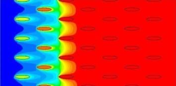
3 Two different geometries are considered. The outer domain is fixed. The inner arrangement of matrix elements is varied on the basis of slenderness ratio. The matrix elements consists of elliptical cross section with slenderness ratios 5 and 10. Slenderness ratio (SR) refers to the ratio of lengths of major axis to minor axis of a given cross section. Here slenderness ratio is varied by changing the length of major axis alone. The minor axis is fixed such that the flow area will not be reduced along the flow direction.since flow area is not reduced the effect of boundary layer remains constant and thereby pressure drop will not be affected. As slenderness ratio increases, the porosity of the channel decreases which will increase the heat transfer area. The effect of flow Reynolds number is also studied for Reynolds numbers ranging from 800 to Figure 2: 2D geometry with elements of SR-5 Figure 3: 2D geometry with elements of SR-10 Figure 4: Meshed domain for slenderness ratio 5 Figure 5: Meshed domain for slenderness ratio RESULTS AND DISCUSSION In the present study the effect of slenderness ratio and flow Reynolds number on chilldown are investigated. Four different cases with Reynolds numbers 800,1000,2000,3000 are simulated. All four flow conditions are considered for both the geometries with SR5 and SR10. Since the flow cross sectional areas remain almost constant, the pressure drop variation is neglected. There will be a small variation due to the effect of increased surface area for less porous flow domain (SR10).The effect of slenderness ratio on chill down for Reynolds number 800 is primarily simulated. Both the geometries of SR5 and SR10 are compared for the given flow. Figure.6 indicates the contours of volume fraction of nitrogen along the channel with mesh elements of SR5 and correspondingly Figure.7 shows the contours of nitrogen distribution for second case of geometry with SR10. The contour of volume fraction of cryogen gives an idea of flow along the matrix elements. The flow pattern is an important parameter in chill down process.


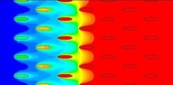
4 T= 0.01 sec T=0.02 sec T=0.03 sec T= 0.04 sec T=0.05 sec T= 0.1sec Figure 6: Contours of volume fraction of nitrogen for slenderness ratio 5 and Re =800 T= 0.01sec T=0.02sec T=0.03sec T=0.04sec T= 0.05sec T= 0.1sec Figure 7: Contours of volume fraction of nitrogen for slenderness ratio 10 and Re =800 The temperature distribution of the flow domain are shown in Figure.8 and Figure.9.Detailed investigation on the contours will help us to understand the temperature changes along same lengths from inlet for both cases with SR5 and SR10. From the time versus heat transfer rate plot it can be found that heat transfer rate is more and faster for second case with SR10. There is an increase in heat transfer rate by 3500W/m 2 K for improved slenderness ratio. As flow rate increases heat transfer rate increases. Studies were conducted for cases with Reynolds numbers ranging from 800 to The figures 10 and 11 refer to distribution of nitrogen along the channel for both cases with SR5 and SR10 at Reynolds number Comparison of contours from figures 6 and 11 gives us a physical idea of nitrogen distribution at various flow times for the same geometrical configuration with SR10 and at different flow conditions with Reynolds numbers 800 and 3000.


5 T= 0.01 sec T=0.02 sec T=0.03 sec T= 0.04 sec T=0.05 sec T= 0.1sec Figure 8: Contours of temperature for slenderness ratio 5 and Re =800 T= 0.01sec T=0.02sec T=0.03 sec T=0.04 sec T= 0.05 sec T= 0.1sec Figure 9: Contours of temperature for slenderness ratio10 and Re =800 T= 0.01 sec T=0.02 sec T=0.03 sec T= 0.04 sec T=0.05 sec T= 0.1sec Figure 10: Volume fraction contours of nitrogen for slenderness ratio 5 and Re 3000


6 T= 0.01sec T=0.02sec T=0.03sec T=0.04 sec T= 0.05sec T= 0.1sec Figure 11: Volume fraction contours of nitrogen for slenderness ratio 10 and Re 3000 T= 0.01 sec T=0.02 sec T=0.03 sec T= 0.04 sec T=0.05 sec T= 0.1sec Figure 12: Temperature contours for slenderness ratio 5 and Re 3000 Thorough understanding of the heat transfer characteristics reveals that it resembles the boiling curve with different regimes.figure.13 shows that for the geometry with slenderness ratio 5, the maximum heat transfer coefficient is when the Reynolds number is 800 and the value is about 14500W/m 2 K.And as Reynolds number increases heat transfer coefficient decreases. The variation of Reynolds number from 800 to 3000 has decreased the heat transfer coefficient by about 10,000W/m 2 K. From figure 14 it can be understood that increase in slenderness ratio of mesh elements have contributed to improved heat transfer rate. But for higher flow velocities the effect of slenderness ratio is less. The heat transfer rate for the flow condition with Reynolds number 3000 is approximately 4500W/m 2 K.
7 Figure 13: Heat transfer coefficient at different Reynolds numbers for slenderness ratio 5 Figure 14: Heat transfer coefficient at different Reynolds numbers for slenderness ratio CONCLUSION The present study gives an understanding of two phase flow and heat transfer phenomenon along a porous channel with staggered matrix elements of elliptical cross section. The influence of slenderness ratio on chill down and the effect of Reynolds number are also discussed. As the porosity of the flow channel is varied by varying slenderness ratio alone, the flow stream cross sectional area is kept constant thereby improving heat transfer rate without affecting pressure drop. Pressure drop and chill down time are involved in most of the cryogenic flow systems. The results obtained shows that by increasing the slenderness ratio from 5 to 10, the heat transfer coefficient is increased by 3500W/m 2 K for a flow Reynolds number of 3000 without compensating the pressure drop. Improved heat transfer rate has decreased the chill down time which saves the amount of liquid nitrogen requirement for chill down.
8 REFERENCES [1] Burke, J.C., Byrnes, W.R., Post, A.H., and Ruccia, F.E 1960, Pressure Cooldown of Cryogenic Transfer Lines Advances in Cryogenic Engineering, 4, pp [2] Graham, R.W., Hendricks, R.C., Hsu, Y.Y., and Friedman.R., 1961, Experimental Heat Transfer and Pressure Drop of Film Boiling Liquid Hydrogen Flowing through A Heated Tube, Advances in Cryogenic Engineering, 6, pp [3] Bronson, J.C., Edeskuty, F.J., Fretwell, J.H., Hammel,E.F, Keller, W.E., Meier, K.L., Schuch, and A.F, Willis.W.L., 1962, Problems in Cool-Down of Cryogenic Systems, Advances in Cryogenic Engineering, 7, pp [4] Velat, C., Jackson. J., Klausner, J.F., and Mei, R., 2004 Cryogenic Two-Phase Flow during Chilldown, Proceedings of the ASME HT-FED Conference, Charlotte. [5] Chi, J.W.H., 1965, Cool down Temperatures and Cool down Time During Mist Flow, Advances in Cryogenic Engineering, 10, pp [6] Cross MF, Majumdar AK, Bennett Jr JC, Malla RB. Model of chill down in cryogenic transfer lines. J Spacecraft Rockets 2002; 39: [7] Chen, J. C., 1966, Correlation for Boiling Heat Transfer to Saturated Fluids in Convective Flow, Industry Engineering Chemistry Process Design and Development, pp [8] Gungor, K. E., Winterton, R. H. S., 1996, A General Correlation for Flow Boiling in Tubes and Annuli International Journal of Heat Mass Transfer, 29, No.3 pp [9] Rogers, J.D., Two phase friction factor.aiche, j.14 (6), pp [10] S Sunil Kumar, Ajaylal P.R., Pressure surges during cryogenic fluid entry into warm feed line. Proceedings of the 21th national and 10th ISHMTASME Heat and mass transfer conference, IIT Madras India.